Article

Glass Surface Modification Was Induced by the Combination of Coating Technology and Femtosecond Laser Assisted Chemical Etching

1
College of Mechanical and Electrical Engineering, Shihezi University, Shihezi 832000, China
2
Industrial Technology Research Institute of Corps, Shihezi 832000, China
*
Author to whom correspondence should be addressed.
Processes 2022, 10(7), 1309; https://doi.org/10.3390/pr10071309
Submission received: 13 June 2022 / Revised: 29 June 2022 / Accepted: 29 June 2022 / Published: 4 July 2022
(This article belongs to the Section Materials Processes)

Abstract

:
Due to its high hardness and high transmittance, ultra-white glass has a strong application prospect in the fields of optoelectronics industry and experimental instruments. However, because of its brittleness, it was still a difficult problem in the machining industry. Surface modification provides a basic research idea for ultra-white glass microstructure processing. An effective method to obtain surface modified area on ultra-white glass was presented. The modified zone on the surface of ultra-white glass was induced by the technique of coating and femtosecond laser-assisted chemical etching. The method combines vacuum coating with femtosecond laser irradiation. Next, the modified glass was processed with highly selective potassium hydroxide solution. In order to control the surface size more efficiently, the optimization experiment of laser parameters and chemical parameters on the machining process was carried out. The experimental results show that the method made the surface modification of ultra-white glass more easily and provides basic research for fabricating microchannels on the material.

1. Introduction

In the process of micro-nano structure, the microporous plate formed by micropore array structure is one of the common structures of biological analysis, screening filtration and heat dissipation devices [1]. Non-conductive brittle materials (such as ultra-white glass) are regarded as substrate materials for microporous array plates due to their excellent properties such as high hardness, corrosion resistance and insulation [2]. Ultra-white glass has the advantages of higher visible light transmittance, high flexural strength and higher microhardness. That can be widely used in the fields such as photovoltaic technology, experimental apparatus and similar matters [3]. Furthermore, they have great application prospects in micro-flow sensors, micro-reaction vessels and other micro-electromechanical systems. Due to brittle characteristics of glass materials, machining of glass remains a great challenge for the machinery industry [4]. The major challenges in Fabrication of glass micropore array structure are the generation of brittle fractures and the propagation of cracks, especially at the exit size [5,6]. Consequently, researchers have put forward a variety of machining methods including ultrasonic machining, electrochemical corrosion, and laser machining.
1996, Sun et al., have investigated that used micro-ultrasonic machining (USM) for fabrication of 3D microstructure whose micro-hole as small as 15 μm in the brittle material with higher aspect ratios [7]. Then at 1999, Egashira et al., used USM to create micropores with a diameter of 5 μm in quartz glass [8]. Yan et al., also proposed combined micro-electrical discharge machining and micro-USM for drilling high aspect ratio micro-hole on glass. Their methodology realized micro-hole of 150 μm diameter and 500 μm depth [9]. Due to the low quality of USM on the surface roughness of machinable materials, the electro-chemical discharge machining (ECDM) process has been studied. Researchers investigated the feasibility of three dimensional (3D) micro-structuring, micro-holes and micro-channels in glass using ECDM process [10,11,12,13]. Additionally, Kim et al., changed some parameters of the ECDM process such as voltage, pulse frequency and duty cycle to improve the quality of micropores and material removal rate on Pyrex glass [14]. However, EDEM was not suitable for high volume production and was limited in hole depth. To meet the manufacturing needs, it is urgent to find a new machining process.
Laser micromachining has been found to be one of the most widely used micro-manufacturing processes for machining difficult-to-cut materials. Nikumb [15] et al., used short pulsed solid-state lasers with pulse durations ranging from nanoseconds to femtoseconds in various glasses (Corning Microslide, Doped Silica, and Fused Silica capillary fibers). Moreover, in order to obtain crater with high surface quality, high processing efficiency and deep-diameter ratio, a hybrid process of femtosecond laser assisted chemical etching (FLACE) has been proposed by scholars [16,17,18,19,20]. Glass and crystal have the characteristics of high purity and wide range of transparency. It is often used as a substrate material for femtosecond laser-assisted chemical etching [21]. Researchers have verified the feasibility of this processing method for microstructure processing on different glasses [22,23,24]. Moreover, some researchers [25] have studied the application of femtosecond laser combined with coating technology in the preparation of periodic structure, structural colorful and birefringence effect on glass surface.
In this paper, we present a simple and effective method to obtain surface modified area on ultra-white glass. Aluminum coating was applied to the ultra-white glass by vacuum coating technology to form a mask. Afterwards, FLACE processing was performed and a significant increase in etching rate in the masked area can be found. The manufacturing of femtosecond lasers can be flexibly controlled by adjusting process parameters such as Al-coated film thickness, laser duration, laser power and defocusing value. The increased and controllability diameter of modified area can be controlled by chemical etching time. In addition, the surface modification changes were characterized and analyzed using scanning electron microscopy. This method is instructive for the study of microchannels or microstructures on the surface of ultra-white glass.

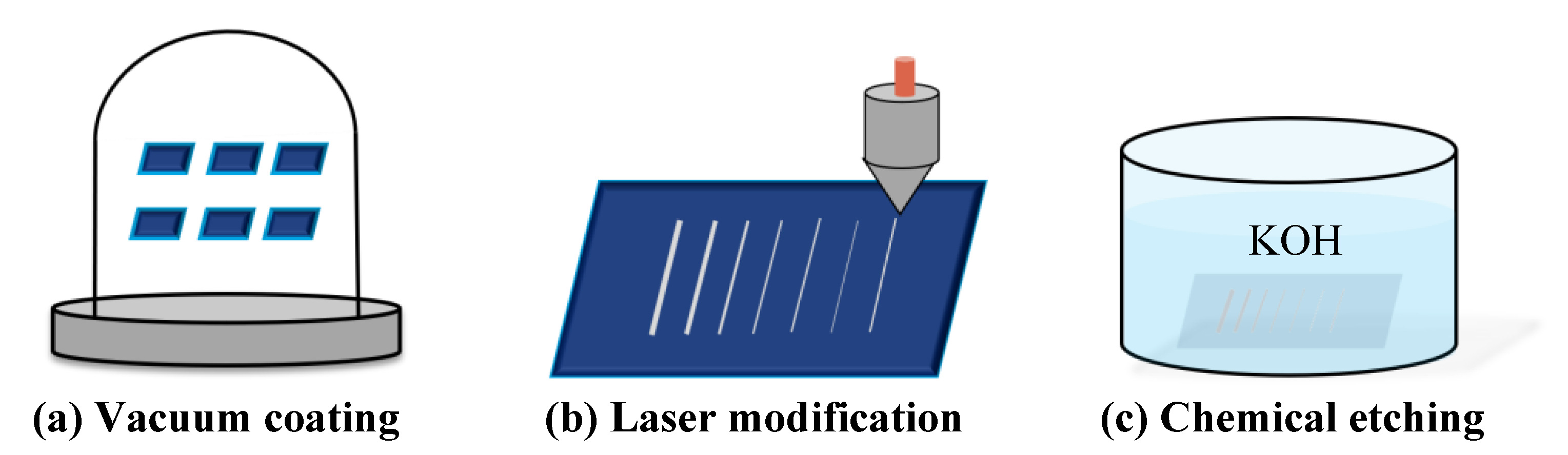
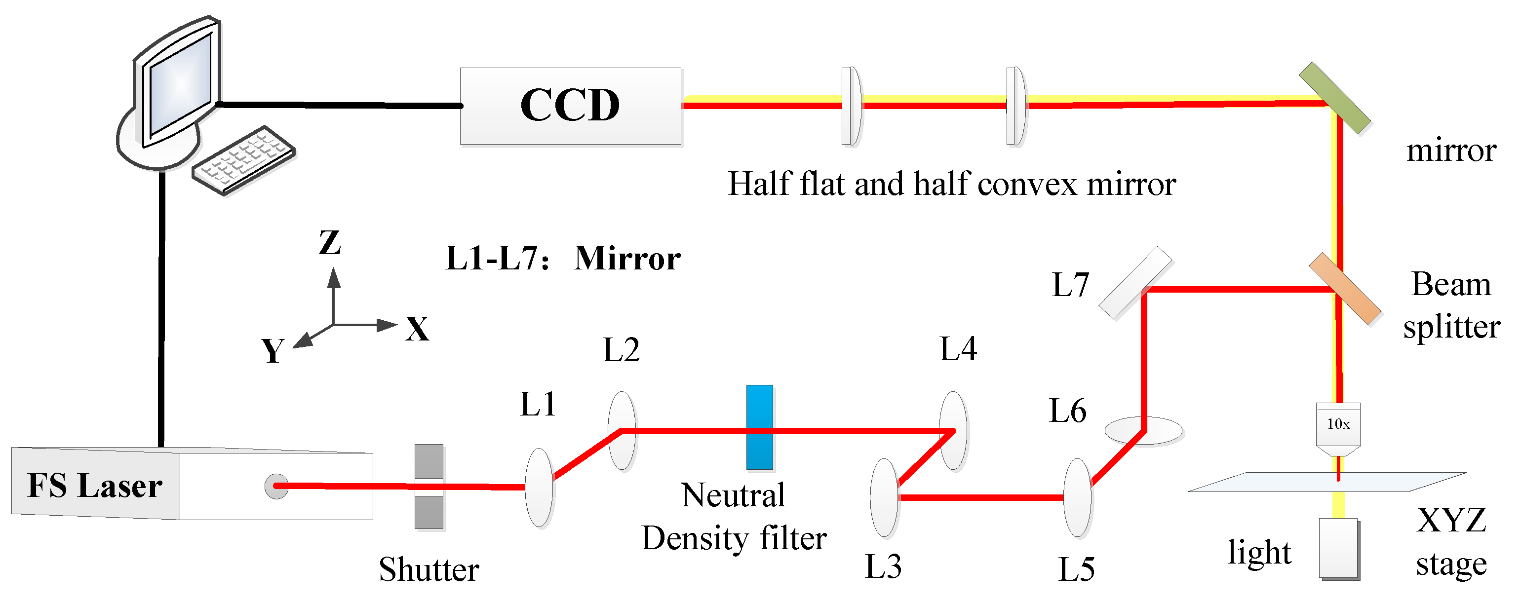
2. Materials and Methods

Ultra-white glass with dimensions of 22 × 22 × 0.15 mm3 was used in the experiment. The fabrication procedure was made up of the following two process: vacuum coating technology and femtosecond laser assisted chemical etching (FLACE includes two steps the laser writing process and the chemical wet etch), as shown in Figure 1. Chemical etching refers to the chemical reaction between materials and etchants, which can improve the surface quality of materials [26]. A femtosecond Ti: sapphire pulsed laser with 35 fs, central wavelength 800 nm and repetition rate 1 kHz were vertically focused into the sample to modify the materials by a 10× objective lens (NA = 0.9, Nikon). In addition, the experimental equipment required was also a programmable three-axis stage, a charge-coupled device camera, and a laser beam control system, as shown in Figure 2 nine ultra-white glass samples were used here, ultrasonic cleaning with distilled water for 15 min and drying in dryer for 10 min. According to the preliminary experiment of coating technology combined with femtosecond laser-assisted chemical etching of ultra-white glass, the aluminum film thickness which can modify the substrate of ultra-white glass was between 2 nm and 20 nm. Therefore, three groups of different aluminum film layers were set for experiment, with the thickness of 5 nm, 10 nm and 15 nm, respectively.
Then, we used two–step FLACE: The sample was fixed onto a computer–controlled 3D translation stage. The geometry of the channel was directly written by translating the sample along the pre–designed path. After that, the sample modified by femtosecond laser irradiation was etched in 15% KOH solution. The range of laser parameters and chemical parameters (Laser duration, Laser power and Etching time) for glass ablation under femtosecond laser assisted chemical etching was obtained by consulting relevant literature and pre–experiments. On this basis, the next step of research. We divided the experiment into nine groups to explore the influence of different parameters on the etching morphology and diameter of modified area. The experimental parameters were shown in Table 1.
We performed femtosecond laser modification on each sample. To investigate the effects of factors such as aluminum film thickness, laser duration and laser power, a one–factor controlled variable method was applied to compare between samples. Laser surface modification were carried out on each sample, and there were three experiments for each group of parameters. Average value is taken when the parameters are analyzed for the result. This process is clearly represented in Figure 3.

3. Results

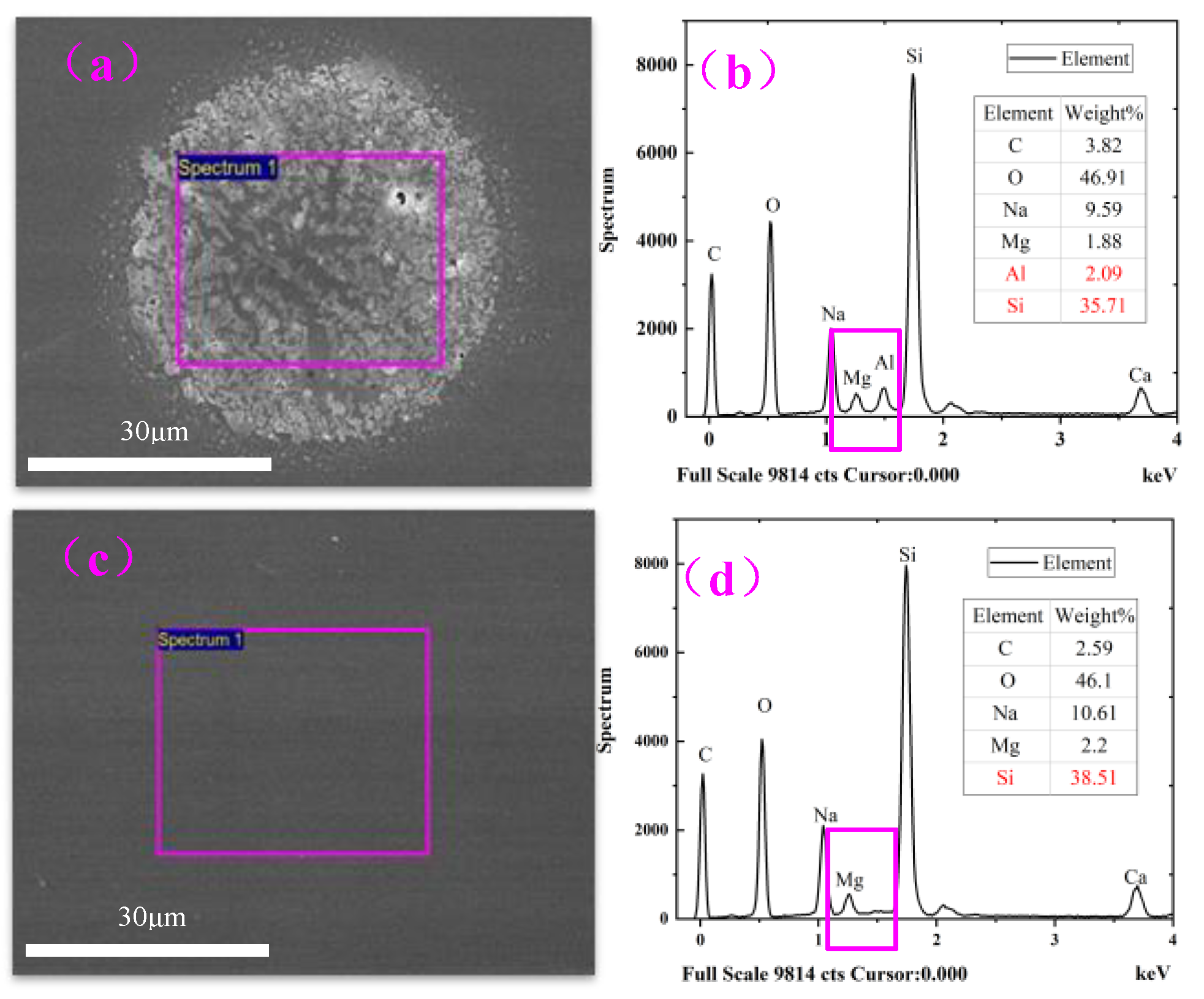
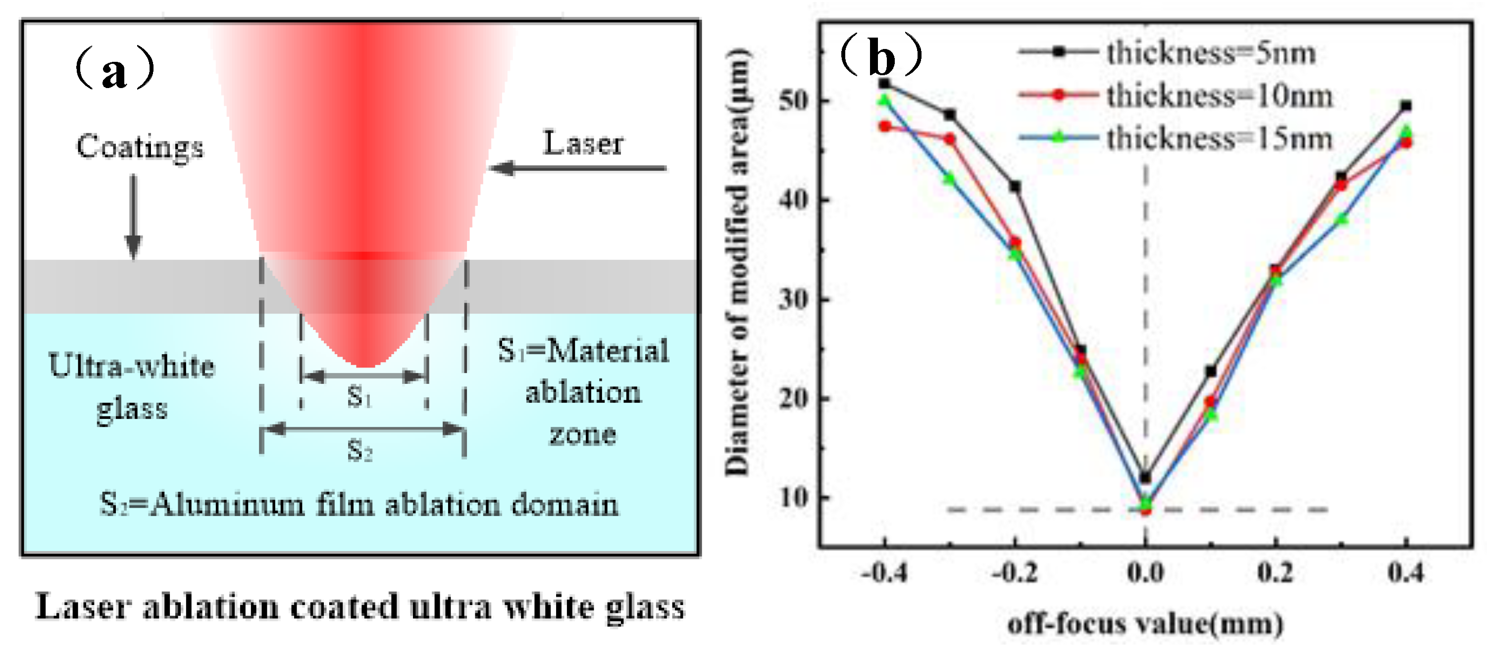
3.1. Laser Induced Modification of Ultra–White Glass

Multiple lines and crater were inscribed in ultra–white glass coated with 5 nm aluminum film, show as Figure 4. While keeping the laser pulse energy constant, the three–dimensional moving stage starts from the focus plane in the Z–axis at distance of 0.05 mm. When glass and metal were heated, molten glass and metal contact, with the rise of temperature will promote the interaction of glass and metal, increase the chemical affinity of each other [27], order to change the surface morphology. Moreover, the matching coefficient of thermal expansion of the two materials was also important for inducing surface modification [28]. In other words, the choice of metal was crucial for bonding with glass.
In order to prove the existence of the modified region, The Scanning Electron Microscope (SEM) was used In addition, the influence of different laser defocusing value on the diameter of the modified area of ultra–white glass was analyzed by SEM. The Scanning Electron Microscope image in Figure 5a–e shown that when defocusing amount was 0.05 mm, ultra–white glass coated with aluminum film was processed by laser with power of 1 W, laser processing time was 4 s, and etched in 15% wt% KOH solution for 3 h. Image (c) was the modified region formed by laser processing in the focal plane; image (a–b) was the modified region formed by laser focusing in the material, and the defocus distance was 0.1 mm and 0.2 mm, respectively. The image (d, e) laser focuses on the outside of the material, and the defocus distance was the same as image (b, a), respectively. At the same time, we can also see from the figure that when the defocus distance was the same, the modified regions are not very different.
Figure 6 shown the SEM and Energy Dispersive X–ray Spectroscopy (EDS) spectra of the ablated and unablated Al–coated glass after etching. EDS analysis was to prove that the aluminum film contributes to the formation of the modified region of ultra–white glass. The results shown that the aluminum film had been reacted and dissolved by the chemical solution. In addition, the surface element was generated by the ultra–white glass after radiation, or the new substance generated by the reaction with the chemical solution.
The main component of ultra–white glass matrix was SiO2. After laser ablation and etched with KOH solution, the weight percentage of Si element was 35.71%, which was 2.8% less than that of the region without laser ablation. This indicates that the modified zone in Figure 6a was formed on the surface of the glass, rather than on the Al film. The Al ion content in the ablated Al–coated glass was 2.09%, while there were no Al ions in adjacent unablated al coated glass matrix. Therefore, it can be known that Al ions did not diffuse into the glass substrate during the deposition process of Al film. In addition, this also indicates that some high–energy Al ions penetrate and embed into the glass surface during laser ablation.
In laser ablation stage, the energy was absorbed by metal and transferred to glass melting and metal bonding, forming modified zone through heat conduction. In the chemical etching stage, the modified material reacts with the etching solution, which promotes the modification of the material. The dissolution reaction mechanism for Al was:
4 Al + 3 O 2 = 2 Al 2 O 3
Al 2 O 3 + 6 KOH = 2 Al ( OH ) 3 + 3 K 2 O
2 Al + 2 KOH + 2 H 2 O = 2 KAlO 2 + 3 H 2
and for SiO2 substrate, it was written [29]:
SiO 2 + 2 OH SiO 2 ( OH ) 2 2
We also carried out laser irradiation on the uncoated ultra–white glass, and no obvious trace of material damage was found. The combination of vacuum coating technology and laser–assisted chemical etching was helpful for surface modification of ultra–white glass materials. In order to obtain better surface effect and faster etching efficiency, it is necessary to reasonably regulate laser irradiation parameters and chemical parameters to improve the current processing technology. We carried out the experiment in Figure 3 and discussed the influence of each parameter on the etching effect with the practical control variable method, as described below.

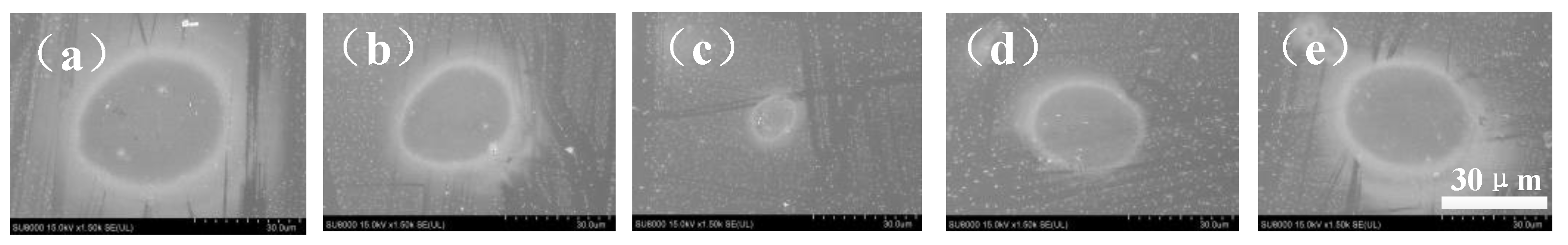
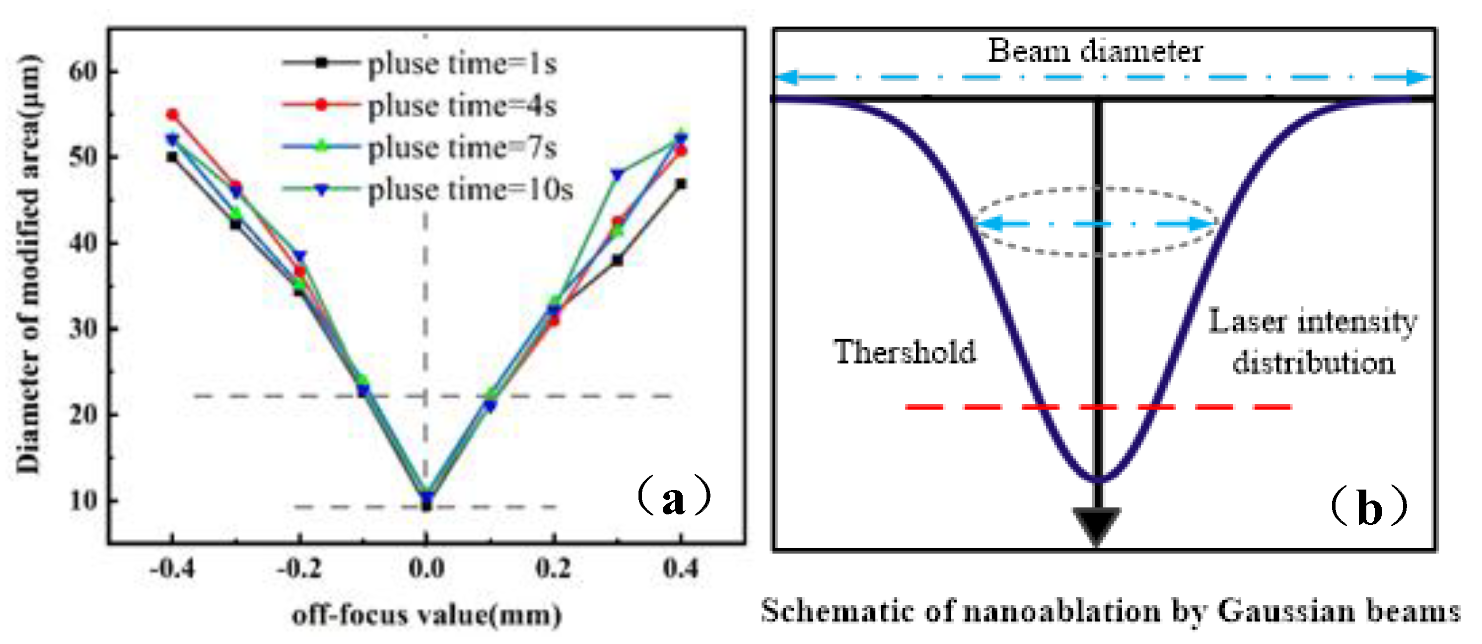
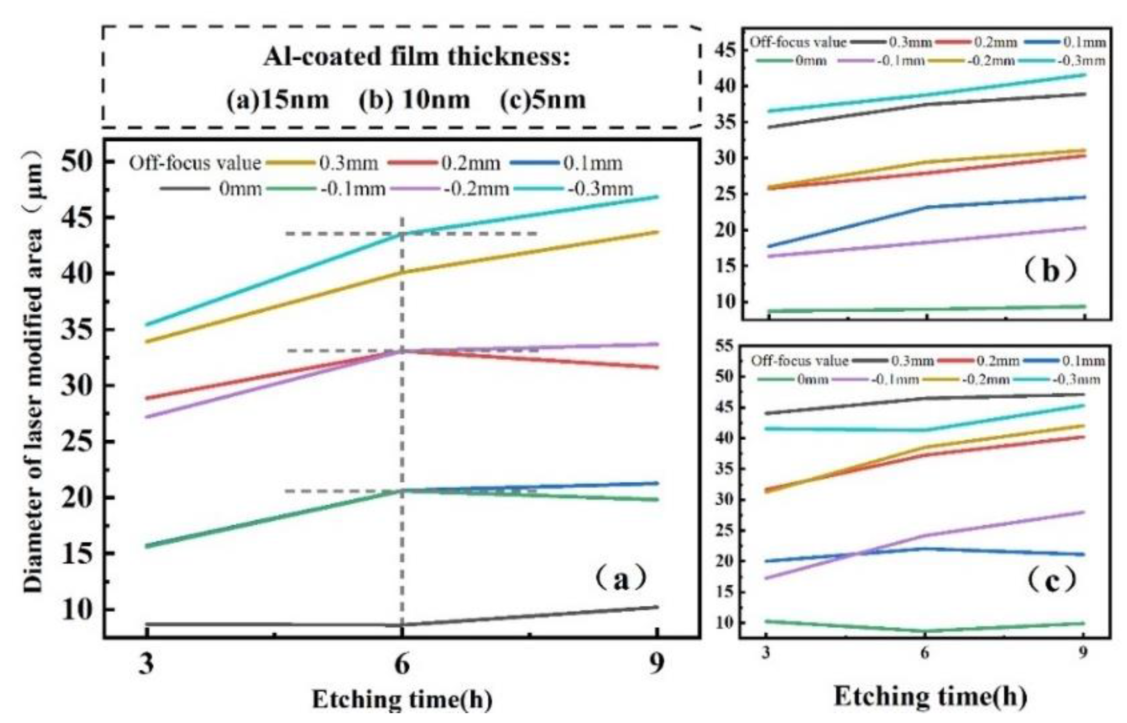
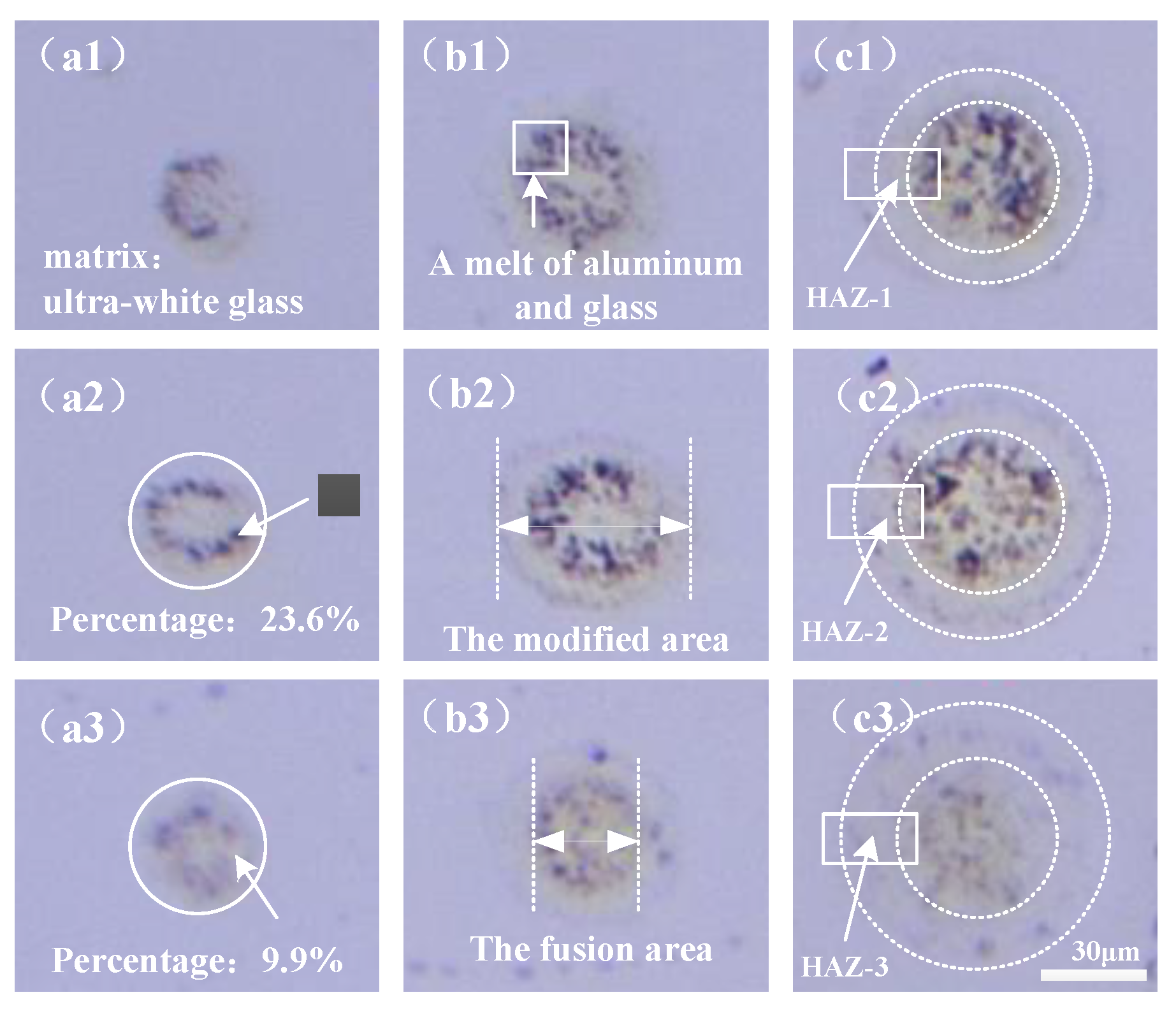
3.2. The Influence of Different Parameters on the Morphology of Craters

This section mainly carried out the process parameter experiment, and studied the influence of pulse time, laser power, laser duration and etching time on the surface modification size. The significance of exploring the surface modification dimension lies in realizing the controllability of the modified area. Additionally, it lays a foundation for future application expansion. The result was shown in Figure 7. It was obvious that there was a certain relationship between defocus amount and the diameter of the modified area. As the laser focus moves away from the focal plane, the surface modification size increases. The relationship between defocus and the diameter of modified area was symmetrically distributed. In other words, when the Z–axis was at the same distance from the focal plane, The diameter of the modified area was roughly the same. Moreover, Figure 7a was the schematic diagram of laser ablative coating ultra–white glass, where S1 region was the ablative region of glass substrate and S2 region was the ablative region of aluminum film. In addition, it can be seen from the figure that the thickness of aluminum film has a comparative influence on S1 region. Figure 7b shows the relationship between defocus amount and diameter of modified area under different aluminum film thickness, which laser duration was 4 s and laser power was 1 W. It can be seen from the results that the smaller film thickness, the larger diameter of the modified area. This result was consistent with that obtained in the figure above. This may be because the thinner the film, the less laser heat was consumed, and the more heat was transferred to the ultra–white glass. Knowing this was helpful in controlling the extent of the surface modification area.
Material ablation threshold is basic research in laser processing, which has an important guiding role in the development of subsequent experiments. The threshold was calculated using a numerical method, which uses laser ablation materials of different energies and records the diameter of the ablation hole. Finally, the ablation threshold was calculated by drawing the corresponding diagram. The specific calculation process was as follows [30]:
φ 0 = 2 E p π ω 0 2
D 2 = 2 ω 0 2 ln ( φ 0 φ t h ) = 2 ω 0 2 ( ln φ 0 ln φ t h )
φ0 (J/cm2) is the energy density at the center of the spot, and ω0 (μm) is the beam waist radius of the spot. D is the diameter of the spot (μm), φth is the ablation threshold.
Formula (4) is the expression of the relationship between the energy density of laser spot φ0 and laser energy Ep. Substituting Equation (4) into Equation (5):
D 2 = 2 ω 0 2 ( ln E p + ln ( 2 π ω 0 2 ) ln φ t h = 2 ω 0 2 ln E p 2 ω 0 2 ln ( 2 π ω 0 2 ) + 2 ω 0 2 ln φ t h
ω0 and φth in Equation (6) are inherent properties of the material and remain unchanged. Therefore, Equation (6) is a linear function with Ep as independent variable. The square of the crater diameter and the log value of the corresponding laser energy were calculated to draw the scatter diagram. After that, the scatter graph is linearly fitted. According to the slope(k) and intercept(b) of the fitted line, the waist radius and ablation threshold of the materials with different film thickness were obtained. The calculation formula is as follows:
ω 0 = k / 2
At the same time, the independent variable of the fitting line is equal to 0, and the formula is obtained:
b = 2 ω 0 2 ln φ t h φ t h = e b / 2 ω 0 2 = e b / k
Therefore, under the action of laser pulse width 35fs and wavelength 800 nm, the values of beam waist radius and ablation threshold of ultra–white glass materials in different coating thicknesses were shown in Table 2.
Figure 8 shown the relationship between different laser durations time and the diameter of surface modification area when laser power was 1 W, aluminum film thickness was 10 nm and etch time was 3 h. The results shown that the effect of laser duration on the diameter of modified areas were not obvious when the defocus quantity was between −0.2 mm and 0.2 mm. At this point, the laser focus was near the focal plane and had enough time to pass through the aluminum film and ablate the glass. However, when the defocus quantity was outside −0.2 mm and 0.2 mm, the processing effect of 1 s pulse time was obviously inferior to 4 s, 7 s and 10 s. The curve image presented in Figure 8a was consistent with the trend of gaussian beam in Figure 8b.
When studying the influence of laser power on the size of the surface modification area, the results obtained were shown in Figure 9. When the laser duration was constant, the laser power was proportional to the diameter of the modified region and had nothing to do with the thickness of the film and defocusing value. That is to say, under different film thickness and defocusing value in this experiment, the diameter of the modified region will still increase with the increase of laser power. In addition, it can be observed from Figure 9 that the curve with aluminum film thickness of 5 nm was always at the top. This can verify another conclusion mentioned above: when the laser durations and defocus amount were constant, the laser power range was 0.4 W~1 W, the thin Al–coated film was easier to acquire modified surface than the thick one.
Figure 10a shown the effect of etching time on the diameter of the modified region when the aluminum film thickness was 15 nm. Experimental data under different defocus conditions were recorded. In summary, the diameter of the laser modified area increases gradually with the etching time. It can be divided into two periods for discussion. In the first period (3–6 h), ultra–white glass coated with aluminum film was put into 15% KOH solution for rapid reaction after laser irradiation area, making the diameter of modified area gradually increase. In the other period (6–9 h), the chemical reaction in the modified zone was not as strong as the previous stage, the increase in physical dimension was slowing down with etching. Since the reaction has entered the saturation stage. In other words, 6 h was the saturation point of the reaction between the Al–coated ultra–white glass and KOH solution after irradiation. Furthermore, the pattern was similar whether the laser is focused inside or outside the material.
As mentioned above, the curve in Figure 10b,c were roughly the same as that in Figure 10a. It is confirmed that the etching time promotes the diameter of the modified region regardless of the thickness of Al film.
The chemical etching time not only has a significant effect on the diameter of the modified region, but also has the following effects on the morphology of the modified region. As can be seen from Figure 11, the pulse power was fixed at 1 W, the laser duration was fixed at 4 s and Al–coated film thickness was fixed at 15 nm. Moreover, the area of the modified region consists of the fusion area (aluminum film was wrapped by molten glass) and the heat affected zone (HAZ). The characteristics of the two regions are obvious. With the increase of etching time, the outline of heat affected area became clearer, as shown in Figure 11(c1–c3). Furthermore, Figure 11(a2,a3) shown that the fusion material between Al film and glass was visibly declined. The ratio of the fusion material to the modified area was calculated by software from 23.6% to 9.9% after etching for 3 h. The cause was the spread of KOH solution deep into the substrate material. The results shown that the etch time has a certain effect on the elimination of Al film residue.

4. Conclusions

In conclusion, this paper demonstrates the etching process of ultra–white glass with Al coating irradiated by femtosecond laser in 15% KOH solution. To verify that this process can promote surface modification, surface elements and morphology of laser–irradiated bare glass and coated glass etched in KOH solution were measured by EDS and SEM. Likewise, the results revealed that the changes of laser and chemical parameters affected not only the size but also the morphology of the modified region.
Experimental show that the diameter of the modified zone was affected by different film thickness. When the laser power, laser duration and defocusing value were constant: the thicker the Al–coated film, the smaller diameter of the modified area. However, when the other parameters were constant, only the laser duration changed the influence on the diameter of the modified region was not significant. When exploring the influence of laser power, it was found that the high power was beneficial to the size of the modified zone regardless of the thickness of the film. It was proved that etching time can augment the diameter of modified region, but there was saturation point. Furthermore, With the increase of etch time, the residues in the modified region will decrease. This work has the potential to provide new insight into the highly efficient and controllable fabrication of microstructures in ultra–white glass.

Author Contributions

Conceptualization, Y.W. and B.X.; methodology, Y.W.; software, S.H.; validation, Y.W., S.H. and C.L.; formal analysis, Y.W.; investigation, Y.W.; resources, Y.W. and B.X.; data curation, Y.W.; writing—original draft preparation, Y.W.; writing—review and editing, B.X. and L.W.; visualization, Y.W.; supervision, B.X. and L.W.; project administration, B.X.; funding acquisition, B.X. All authors have read and agreed to the published version of the manuscript.

Funding

This research was funded by Shihezi University Young Teachers Research Ability Enhancement Program, grant number ZZZC201739B, and High–level Talents Project of Shihezi University, grant number RCSX201737.

Institutional Review Board Statement

Not applicable.

Informed Consent Statement

Not applicable.

Data Availability Statement

Not applicable.

Conflicts of Interest

The authors declare no conflict of interest.

References

  1. Peters, D.; Drallmeier, J.; Bristow, D.A. Sensing and Control in Glass Additive Manufacturing. Mechatronics 2018, 56, 188–197. [Google Scholar] [CrossRef]
  2. Zhang, X.W.; Zhang, Y.Q.; Li, M. Ultra-White Glass. CN Patent CN102092941 B[P], 14 November 2012. [Google Scholar]
  3. Huang, L.; Cao, Y.; Jia, F.; Lei, Y. Study on the stability of gas film in electrochemical discharge machining of ultra-white glass micro array holes. Microsyst. Technol. 2019, 26, 947–955. [Google Scholar] [CrossRef]
  4. Jahan, M.P.; Perveen, A.; Rumsey, A.M. A review on the conventional, non-conventional, and hybrid micromachining of glass. Mach. Sci. Technol. 2019, 23, 264–338. [Google Scholar] [CrossRef]
  5. Park, B.J.; Choi, Y.J.; Chu, C.N. Prevention of exit crack in micro drilling of soda-lime glass. CIRP Ann. Manuf. Technol. 2002, 51, 347–350. [Google Scholar] [CrossRef]
  6. Kim, H.H.; Chung, S.C. Optimization of diamond micro-drilling processes in glass machining. In Proceedings of the ASPE 22nd Annual Meeting, Dallas, TX, USA, 14–19 October 2007. [Google Scholar]
  7. Sun, X.Q.; Masuzawa, T.; Fujino, M. Micro ultrasonic machining and its applications in MEMS. Sens. Actuators A Phys. 1996, 57, 159–164. [Google Scholar] [CrossRef]
  8. Egashira, K.; Masuzawa, T. Microultrasonic machining by the application of workpiece vibration. CIRP Ann. Manuf. Technol. 1999, 48, 131–134. [Google Scholar] [CrossRef]
  9. Yan, B.H.; Wang, A.C.; Huang, C.Y.; Huang, F.Y. Study of precision micro-holes in borosilicate glass using micro EDM combined with micro ultrasonic vibration machining. Int. J. Mach. Tools Manuf. 2002, 42, 1105–1112. [Google Scholar] [CrossRef]
  10. West, J.; Jadhav, A. ECDM methods for fluidic interfacing through thin glass substrates and the formation of spherical microcavities. J. Micromech. Microeng. 2007, 17, 403–409. [Google Scholar] [CrossRef]
  11. Lee, E.S.; Howard, D.; Liang, E.; Collins, S.D.; Smith, R.L. Removable tubing interconnects for glass-based micro-fluidic systems made using ECDM. J. Micromech. Microeng. 2004, 14, 535–541. [Google Scholar] [CrossRef]
  12. Cao, X.D.; Kim, B.H.; Chu, C.N. Micro-structuring of glass with features less than 100 mm by electrochemical discharge machining. Precis. Eng. 2009, 33, 459–465. [Google Scholar] [CrossRef]
  13. Zhang, Z.; Liu, W.; Song, Z. Particle size and surfactant effects on chemical mechanical polishing of glass using silica-based slurry. Appl. Opt. 2010, 49, 5480–5485. [Google Scholar] [CrossRef] [PubMed]
  14. Kim, D.; Ahn, Y.; Lee, S.; Kim, Y. Voltage pulse frequency and duty ratio effects in an electrochemical discharge micro-drilling process of Pyrex glass. Int. J. Mach. Tools Manuf. 2006, 46, 1064–1067. [Google Scholar] [CrossRef]
  15. Nikumb, S.; Chen, Q.; Li, C.; Reshef, H.; Zheng, H.Y.; Qui, H.; Low, D. Precision glass machining, drilling and profile cutting by short pulse lasers. Thin Solid Film. 2004, 477, 216–221. [Google Scholar] [CrossRef] [Green Version]
  16. Agarwal, A.; Tomozawa, M. Surface and bulk structural relaxation kinetics of silica glass. J. Non-Cryst. Solids 1997, 209, 264–272. [Google Scholar] [CrossRef]
  17. Juodkazis, S.; Nishi, Y.; Misawa, H. Femtosecond laser-assisted formation of channels in sapphire using KOH solution. Phys. Status Solidi (RRL)-Rapid Res. Lett. 2008, 2, 275–277. [Google Scholar] [CrossRef]
  18. Fukata, N.; Yamamoto, Y.; Murakami, K. In situ spectroscopic measurement of transmitted light related to defect formation in SiO2 during femtosecond laser irradiation. Appl. Phys. Lett. 2003, 83, 3495–3497. [Google Scholar] [CrossRef] [Green Version]
  19. Boero, M.; Oshiyama, A.; Silvestrelli, P.L.; Murakami, K. Free energy molecular dynamics simulations of pulsed-laser-irradiated SiO2: Si–Si bond formation in a matrix of SiO2. Appl. Phys. Lett. 2005, 86, 201910. [Google Scholar] [CrossRef] [Green Version]
  20. Miura, K.; Shimotsuma, Y.; Sakakura, M. Feratosecond fluorescence spectroscopy and near-field spectroscopy of water-soluble tetra(4-sulfonatophenyl) porphyrin and its J-aggregate. J. Photo Chem. Photobiol. A-Chem. 2006, 178, 192–200. [Google Scholar] [CrossRef]
  21. Liu, H.; Lin, W.; Hong, M. Hybrid laser precision engineering of transparent hard materials: Challenges, solutions and applications. Light Sci. Appl. 2021, 10, 162. [Google Scholar] [CrossRef]
  22. Corbari, C.; Champion, A.; Gecevičius, M.; Beresna, M.; Bellouard, Y.; Kazansky, P.G. Femtosecond versus picosecond laser machining of nano-gratings and micro-channels in silica glass. Opt. Express 2013, 21, 3946. [Google Scholar] [CrossRef] [Green Version]
  23. Bellouard, Y.; Colomb, T.; Depeursinge, C.; Dugan, M.; Said, A.A.; Bado, P. Nanoindentation and birefringence measurements on fused silica specimen exposed to low-energy femtosecond pulses. Opt. Express 2006, 14, 8360. [Google Scholar] [CrossRef] [Green Version]
  24. Du, K.; Jiang, L.; Li, X.; Zhang, H.; Wang, A.; Yao, Z.; Pan, C.; Wang, Z.; Li, M.; Grigoropoulos, C.P.; et al. Chemical etching mechanisms and crater morphologies pre-irradiated by temporally decreasing pulse trains of femtosecond laser. Appl. Surf. Sci. 2018, 10, 272. [Google Scholar] [CrossRef]
  25. Chen, L. Femtosecond Laser-Induced Periodic Structures on the ITO Film and Glass Surface and Laser Processesing of Cooling Holes in Turbine Blade. Ph.D. Dissertation, East China Normal University, Shanghai, China, 2021. [Google Scholar]
  26. Xu, L.; Wang, L.; Chen, H.Y.; Wang, X.; Chen, F.Y.; Lyu, B.H.; Hang, W.; Zhao, W.H.; Yuan, J.L. Effects of pH values and H2O2 concentrations on the chemical enhanced shear dilatancy polishing of tungsten. Micromachines 2022, 13, 762. [Google Scholar] [CrossRef] [PubMed]
  27. Zhang, F. Thermodynamic basis of glass-metal sealing (Continued 3). Glass Enamel 1988, 1, 53–58. [Google Scholar]
  28. Duffie, J.A.; William, A.; Beckman. Solar Engineering of Thermal Processes; New York John Wiley & Son. Inc.: New York, NY, USA, 1991; pp. 35–39. [Google Scholar]
  29. Seidel, H.; Csepregi, L.; Heuberger, A.; Boumgortel, H. Anisotropic etching of crystalline silicon in alkaline solutions. J. Electrochem. Soc. 1990, 137, 3612–3626. [Google Scholar] [CrossRef]
  30. Wang, Q. Generation and Application of Micro Structures on Monocrystalline Silicon Fabricated by Femtosecond Laser Irradiation and Wet Etching. Ph.D. Dissertation, Shandong University, Jinan, China, 2021. [Google Scholar]
Figure 1. Schematic diagram of the fabrication process. (a) Aluminum film was evaporated in a vacuum; (b) Laser modification with accurate dynamic laser parameter regulation; (c) 15% KOH Aqueous solution etch for 3 h, 6 h and 9 h, respectively, at room temperature.
Processes 10 01309 g001
Figure 2. Ultra–white glass processing system by laser irradiation.
Processes 10 01309 g002
Figure 3. Behavioral path of the Single factor controlled variable approach: the effect of changing the one parameter (Aluminum film thickness, laser duration, Laser power, Etching time) under the same.
Processes 10 01309 g003
Figure 4. Microscope image of laser processing of aluminum film thickness at 5 nm. (a) laser power is fixed at 1 w, laser duration is fixed at 4 s; (b) Draw a straight line, direct writing speed is fixed at 0.25 mm/s; (c) Laser direct writing at 0–360° machining Angle.
Processes 10 01309 g004
Figure 5. (ae) SEM image of ultra–white glass with 5 nm aluminum film etched by 15% wt% KOH for 3 h.
Processes 10 01309 g005
Figure 6. SEM images and EDS of laser ablated and unablated regions Al–coated film etched by 15%wt% KOH solution for 3 h. (a) SEM image of laser ablation regions. (The laser power is 1 W, the defocus is 0.2 mm, and the laser processing time is 4 s); (b) EDS image of laser ablation area; (c) SEM image of laser unablated regions. (d) EDS image of unablated area.
Processes 10 01309 g006
Figure 7. (a) laser duration = 4 s, laser power = 1 W, etching time = 3 h: The relationship curve between defocusing amount and diameter of the modified area under different aluminum film thickness (5 nm, 10 nm, 15 nm). (b)Schematic of nano–ablation by Gaussian beams.
Processes 10 01309 g007
Figure 8. (a) When aluminum film thickness = 10 nm and laser power = 1 W, the relationship curve between defocus amount and diameter of modified region at different pulse times (1 s, 4 s, 7 s and 10 s). (b) Schematic diagram of Gauss formula ablation.
Processes 10 01309 g008
Figure 9. When laser duration = 4 s, aluminum film thickness = 5 nm, 10 nm, 15 nm: the relationship curve between different laser powers (0.4 W, 0.6 W, 0.8 W, 1 W) and the diameter of Surface modified area. Defocus volume is (a) −0.1 mm; (b) 0.1 mm; (c) −0.2 mm; (d) 0.2 mm.
Processes 10 01309 g009
Figure 10. Under different defocuses, the relationship between the diameter of the laser modified area of aluminized ultra–white glass and the etching time is shown. The pulse power is fixed at 1 W, the laser duration is fixed at 4 s and Al–coated film thickness is fixed at (a) 15 nm, (b) 10 nm and (c) 5 nm.
Processes 10 01309 g010
Figure 11. Microscope images of laser–ablated Al–coated ultra–white glass followed and subsequently etched in 15% KOH solution in different conditions: (a) etching time = 3 h, (b) 6 h, (c) 9 h. (1) defocusing distance = 0.1 mm, (2) 0.2 mm, (3) 0.3 mm. All the sub images have the same scale bar.
Processes 10 01309 g011
Table 1. Experimental parameter design: make samples with different laser parameters and set different chemical etching parameters.
Aluminum Film Thickness (nm)Laser Duration (s)Laser Power (w)Etching Time (h)
511.03
1040.86
1570.69
100.4
Table 2. The waist radius diameter and ablation threshold of different film thickness. laser duration = 1 s, defocusing amount = −0.1 mm.
Aluminum Film Thickness (nm)SlopeIntercept (μm2) ω 0   ( μ m ) φ t h   ( J / c m 2 )
5778.291319.8019.730.183
10949.431068.1021.790.325
151197.601285.8024.470.342
Publisher’s Note: MDPI stays neutral with regard to jurisdictional claims in published maps and institutional affiliations.

