1. Introduction
Natural Gas Hydrates (the abbreviation is NGH and also known as combustible ice) is a new type of clean energy. Natural gas hydrates are ice-like structures of a water lattice with cavities, which contain guest gases. A very important property of natural gas hydrate is that natural gas can be found in the natural gas hydrate crystals. It is estimated that the global reserves of natural gas hydrates are about
m
, the total amount of which is about twice the total amount of proven oil and gas in the world [
1,
2,
3,
4]. Among the sediments, compared with the traditional oil and gas resources, it has the advantages of shallow-buried depth and large reserves. At present, with the continuous consumption of fossil energy, a large amount of
and
have caused great damage to the ecological environment. As a conventional energy, natural gas can significantly reduce
emissions as shown in
Figure 1. Compared with traditional fossil energy, such as coal and propane, the
discharge by natural gas has decreased by 16–50%. As the main contributor to the greenhouse effect, the decrease of
emission restrains the occurrence of ecological disasters substantially. Furthermore, the common pollutants discharged from natural gas also include up to 1.3%
, 1%
, i.e., there is virtually no metal or carbon-based complex chemical pollution. However, the pollutants from oil include
,
, some
and minor metals, some hydrocarbon volatiles and chemicals. The pollutants from coal include
,
,
,
,
, Dioxins,
,
,
B,
,
,
V,
,
,
,
,
,
,
,
,
U,
,
,
,
,
. Volatile and Polycyclic Aromatic hydrocarbons, other radionuclides, formaldehyde, and toluene are also observed. Therefore, natural gas is a kind of low-pollution energy in terms of pollutant content and types [
5,
6].
All countries in the world attach great importance to the exploration and development of natural gas hydrates in order to respond to energy emergencies. The stability condition for NGH is low temperature and high pressure. These conditions can exist at shallow depth below the seabed. The decomposition of NGH can happen when the nature of the formation or vibration changed. Then, the natural gas can volatilize from the stratum [
7,
8,
9]. The properties of the drilling fluid will change and cause irregular vibration of the drill string, which may eventually lead to unwanted vibration of the drill string. Conversely, the vibration of the drill string will change surroundings and aggravate the decomposition of hydrates. Meanwhile, severe vibration can easily induce serious drilling accidents such as formation collapse. As an important part of drilling, the drill string is a key factor in determining the success of the drilling process [
10,
11]. During the drilling process, the drill string is subjected to a large sudden change of stress caused by the alternating load, and it often fails prematurely. Drill string failure has always been a difficult problem in international oilfield development. In China, there are at least 500 drill string failure accidents in oil and gas fields every year, with direct economic losses of more than 40 million yuan. SPE/Drilling Engineering published an article in May 1992, in which drilling conditions of five vertical wells in West Africa from 1987 to 1988 were introduced. The depths of these five wells are between 2591–3962 m. A total of 66 fracture accidents occurred during the drilling process, on average, 13.2 times for each well and an average loss of 20,000 dollars per accident [
12,
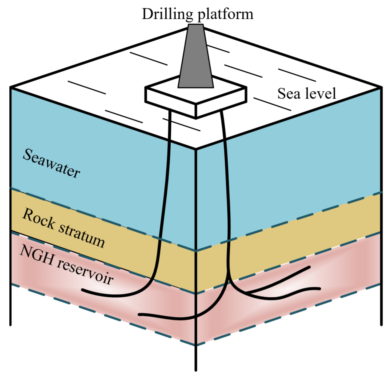
13]. Offshore exploitation of gas hydrate is more complex than onshore exploitation of oil and gas. Natural gas will be incorporated into the drilling fluid in the annulus (the space between the drill string and the wellbore). A schematic diagram of natural gas hydrate drilling is shown in
Figure 2.
The vibration damping of the drill string mainly comes from the liquid in the annulus, and the decomposition of natural gas hydrate just affects the properties of the liquid. The liquid in the annulus mainly affects the lateral vibration of the drill string, as shown in
Figure 3. The two most common types of damping in axial models include: viscous damping and structural damping. The damping of the liquid in the annulus can be thought of as Riley damping (quadratic expression for the rate of energy dissipation), which is proportional to the mass and stiffness. In the absence of a primary source of dissipation, Riley damping is responsible for the low-frequency behavior with mass dependence and the high-frequency behavior is related to a stiffness dependence. The assumption of annular drilling fluid as Riley damping can result in more accurate predictions [
14,
15]. The damping force is introduced while applying the mass proportional to the damping coefficient, which is caused by the absolute velocity of each node. This phenomenon can be used to model objects moving in viscous liquids. In the process of modeling, it is considered that any point in the model is close to the critical damping [
16]. Ghasemloonia et al. regarded drilling fluid damping in the annulus as a drag force (proportional to the square of the velocity) [
17]. Spanos et al. studied the damping equation in the finite element model, which is a function related to operating frequency and the liquid density. They considered Riley damping and gyration, and divided the damping matrix into dissipative and non-dissipative matrices [
18]. Paidoussis et al. studied the influence of drilling fluid flowing in the drill string and the annulus, and they found that the influence of fluid flow inside and outside the drill string is very sensitive to the annulus [
19]. Zhang et al. studied the effect of fluid flowing on the load transfer ability of the drill string. They proposed a two-dimensional model with a vertical drill string fixed at both ends, and found the critical flow rate of drilling fluid when the drill string buckled. Meanwhile, the relationship between the length of the drill string and fluid flow rate is also presented. In the buckling analysis, they also studied the effect of fluid density on buckling. However, they did not study the effect of damping on stability analysis and multiple lateral contacts [
20,
21]. Ritto et al. analyzed the effect of mud flow on the natural frequency and dynamic behavior of the drill string. They found that the axial and torsional behaviors are not very sensitive to the flow of drilling fluid. They also found that the lateral natural frequency changes little when fluid is considered. When the fluid velocity is considered in the kinetic equation, the lateral dynamic response is somewhat large initially. However, the steady-state response does not change [
22]. In conclusion, most studies do not study the fully coupled model, that is, they rarely consider the comprehensive influence of the vibration of the drill string in three directions, the action of drilling fluid, the invasion of natural gas and other factors on the vibration of the drill string at the same time.
Bifurcation theory is a theory in mathematics that studies the change of a group of curves in essence or topological structure. A group of curves may be integral curves in a vector field or solutions of a group of differential equations. Bifurcation is often used in the study of dynamic systems. It refers to the sudden change of a system essence or topology caused by the small and continuous change of system parameters. In this paper, the bifurcation theory is used to study the effect of drill string length and angular velocity on the system response. The change of these two parameters causes a sudden change in the dynamic behavior of the drill string (system response), which can be clearly distinguished by the bifurcation diagram. A coupled nonlinear dynamic model of the drill string is presented with the fluid–solid coupling vibration, the nonlinear rub-impact, and centralizer configuration. Then, the relationship between the variable parameters of the drill string and the complex dynamic characteristics of the drill string is analyzed.
2. Proposed Method
In this section, the specific mathematical model is described. In the static drilling fluid, the gas mixed into the drilling fluid does not work in the vertical direction; however, when compressed in the horizontal direction, it has no effect on the pressure. If the drilling fluid flows, the position of gas bubbles changes constantly, and the pressure of the two-phase fluid also changes. The drilling fluid inside and outside the drill string will cause additional hydrodynamic pressure in the fluid, which will directly affect the longitudinal vibration of the drill string. Through the coupling of longitudinal vibration, lateral and torsional vibration, the vibration of the entire drill string is affected [
23]. Considering the coupling effect of drilling on the fluid dynamic pressure, the effect of drilling fluid on the lateral vibration is equivalent to the inertial force. The additional longitudinal force of the drill string caused by drilling fluid can be given as:
where
p denotes the additional longitudinal force per unit length,
is the Poisson ratio of the drill string,
is the cross-sectional area inside the drill string,
is the cross-sectional area outside the drill string.
and
are the pressure of the drilling fluid inside and outside the drill string, respectively.
After the drill string is in contact with the well wall, rub-impact will occur. At the moment of impact and friction, the displacement of the drill string will not change. However, the lateral speed of the drill string will jump instantly while impacted. The torsional and longitudinal vibration of the drill string will also jump while friction occurs. When rub-impact occurs, the impulse changes the momentum of the drill string without affecting its position, which belongs to the impulse differential system. The impulse differential system is a differential equation with constrained equations. The transition equation of two-dimensional rotor velocity is generalized to the transition equation of three-dimensional drill string velocity, which is the constrained equation in the dynamic equation of the drill string vibration. According to the impulse theorem, the direction of normal velocity will be reversed before and after the drill string impact with the borehole wall. In addition, the speed of the drill string will also change. The following equation can be obtained:
where
m is the mass of the drill string,
is the friction force in axial direction,
is the friction force around the circumference,
N is the normal impact force.
and
are the axial velocity before and after impact, respectively.
and
are the velocity of the circumference before and after impact, respectively.
and
are the normal velocity before and after impact, respectively.
According to Coulomb’s law of friction, the friction is related to the normal force. The equation can be obtained:
where
and
denote the axial and tangential friction coefficients, respectively.
The constrained equation in the dynamic equation of the drill-string impulse vibration is obtained based on Equations (
2)–(
6) and the velocity before and after the impact between the drill string and borehole wall.
where
is the restitution coefficient of impact.
The displacement of the drill string can be written as:
where
u,
v,
w are the axial, circumferential, and lateral displacement in any point on the neutral plane (
) of the drill string.
The equations can be obtained according to the nonlinear shell theory:
The drill string can be simplified to two independent stiffnesses (
and
) under the premise that the drill string is composed of a single material. The following equations can be obtained:
where
E is the elasticity modulus of the drill string.
v is the Poisson ratio.
is the initial axial stress.
is the initial torsional stress.
,
.
The axial, circumferential, and lateral displacements are assumed as functions without
dependence according to the features of the slender drill string. Therefore, Amabili’s nonlinear cylindrical shell theory is extended and applied to the drill string model. Dynamic equations in partial differential form are proposed according to Hamilton’s Principle:
Equations (
19)–(
21) are the vibration differential equations in three directions. It can be found that the circumferential vibration is decoupled from the other two directions. Such a simplification is reasonable when the axial dimension of the drill string is much larger than the circumferential dimension (about 3900 times in this paper). Meanwhile, Equations (
7)–(
9) and (
19)–(
21) form an impulse differential system. The lateral vibration, as an important vibration mode, has great influence on the stability of the borehole wall. The number of centralizers is closely related to the mode of lateral vibration. In this paper,
n centralizers are set at intermediate intervals for a drill string with a total length of
L. Thus, the drill string is divided into
n sections. Taking the low-frequency and large-amplitude modes on the drill string with the rub-impact between the drill string and the borehole wall, we obtain
We substitute Equations (
22)–(
24) into Equations (
19)–(
21). Then, we integrate in the length direction after multiplying both sides by the corresponding modal function. The motion equations can be obtained through applying the orthogonality of the trigonometric function:
3. Numerical Results and Discussion
This section presents the results from applying the mathematical model revealed in
Section 2. Different angular velocities and lengths of the drill string are applied in this section in order to find the relationship between the complex dynamic behavior and the parameters of the drill string. In the numerical results,
,
,
,
,
, and
are the projections of the vibration vector on the complex plane, which is equal to the vibration vector described as the amplitude and the phase.
and
are in axial direction.
and
are in torsional direction.
and
are in lateral direction. Input parameters applied in this paper are listed in
Table 1.
3.1. Angular Velocity and System Response
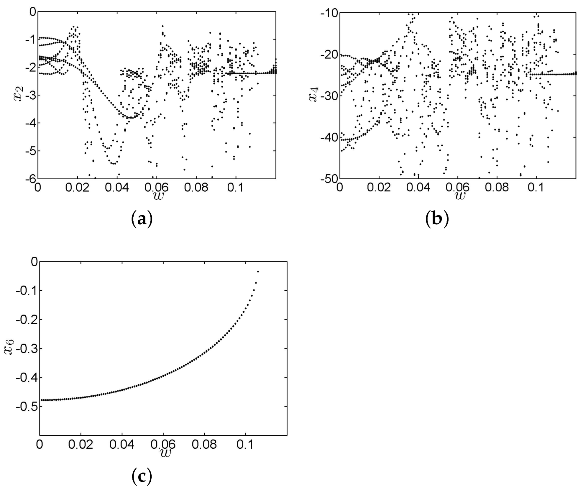
According to the formula, the law of the variation of the amplitude of the drill string in three directions with the angular velocity is obtained, as shown in
Figure 4. With the increase of angular velocity (which has been converted into a dimensionless quantity), the lateral bifurcation diagram shows an upward trend. However, the
y-axis of the image is negative; so, the lateral amplitude decreases, and the amplitude is closer to zero than that obtained for a smaller angular velocity. The reason is that the angular velocity is reflected in the stiffness term in the equation. The higher the angular velocity, the greater the stiffness of the lateral vibration of the system and the smaller the amplitude. The axial and torsional vibrations of the system experience a process from multiple periodic motion to almost periodic motion and, then, to periodic motion with the increase of angular velocity. Meanwhile, the amplitudes of axial and torsional vibrations are smaller (closer to the zero point of the
y-axis) when the angular velocity approaches zero. With the increase of the angular velocity, the amplitude becomes larger and more complex. When the angular velocity exceeds 0.11, the two amplitudes return to near zero, and the vibration tends to be stable.
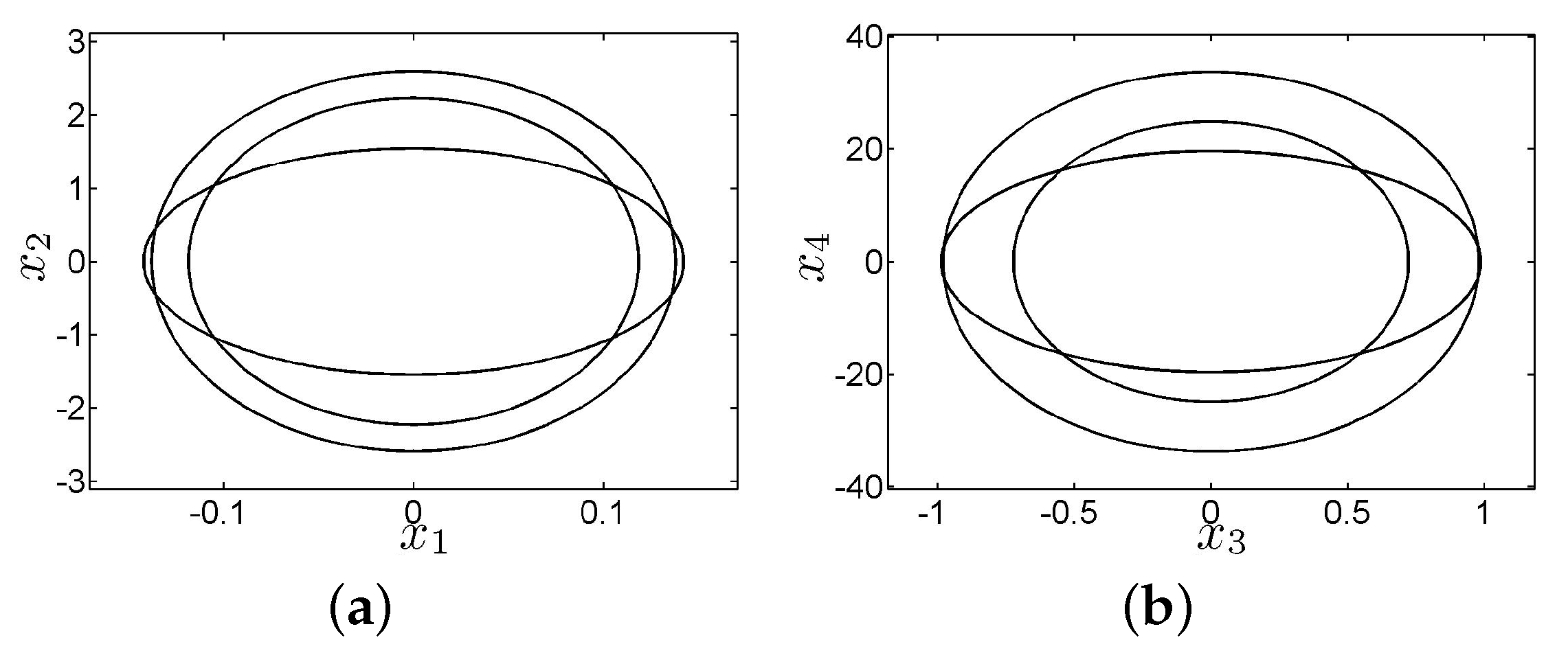
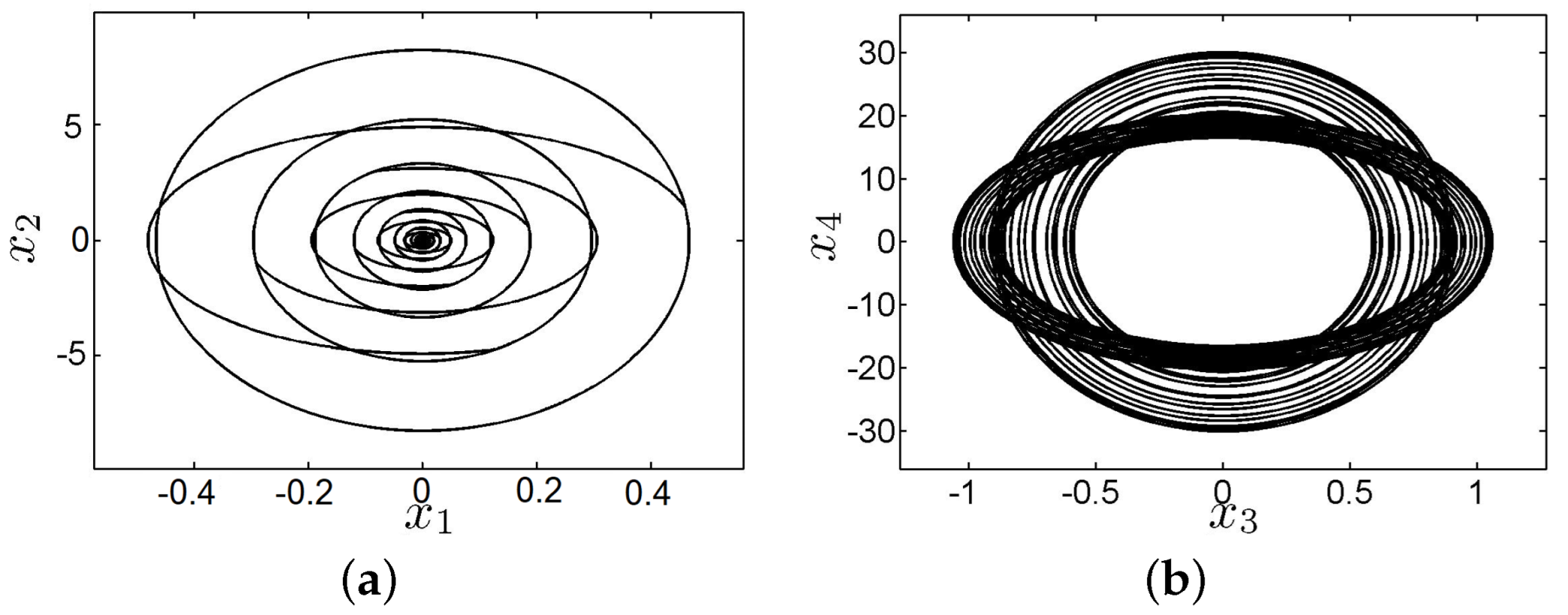
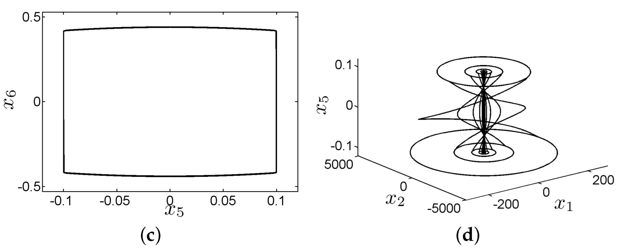
The system response is shown in
Figure 5 when the angular velocity increases to 0.06. The lateral vibration of the system has a jump phenomenon. Thus, there is rub-impact in the system. The jump phenomenon directly causes a jump to the axial and torsional vibration of the system. It can be seen from the three-dimensional phase diagram that the friction phenomenon of the system in the axial motion will make the system jump from one limit cycle to another limit cycle, and there are rich nonlinear dynamic phenomena in the system. Severe vibration can easily lead to wellbore instability and NGH reservoir anomalies.
The system response is shown in
Figure 6 when the angular velocity increases to 0.11. The response is a triple-periodic motion, the vibration is simplified, and the amplitude of vibration is reduced. It can be seen from the phase diagram of lateral vibration that this is the rub-impact of the system, which is manifested as unilateral rub-impact. The transition from bilateral to unilateral rub-impact of the system is the main reason why the vibration form of the system is simplified and the amplitude is reduced. The results show that if the vibration is complex and the amplitude is large, the vibration of the drill string can be made more stable by increasing the rotational speed, and the probability of drill string damage or borehole wall will inevitably be reduced.
As the angular velocity increases the lateral vibration of the drill is weakened, and the system has experienced the process from multiple periodic motions to an almost periodic motion and then to periodic motion. The rub-impact caused by the transverse vibration is also alleviated. It greatly extends the life of the drill string, and prevents the borehole wall and NGH formation from collapsing.
3.2. The Length of Drill String and System Response
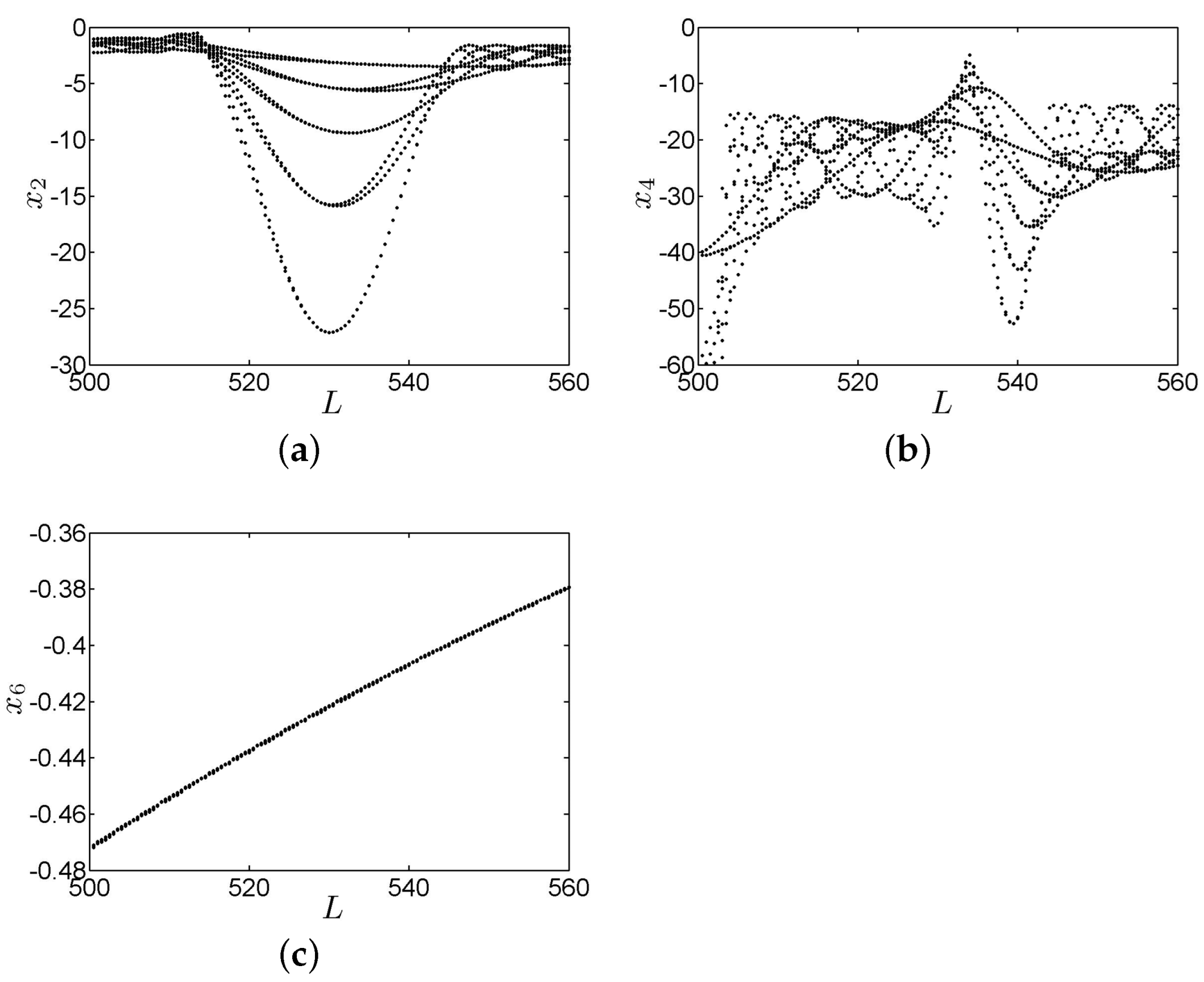
The length of the drill string is different for different well depths, which is also an important parameter that affects the system response. The bifurcation diagrams of the system in three directions are shown in
Figure 7. It can be seen from the figure that the amplitude of the lateral vibration is relatively stable, but the extreme value of the lateral amplitude changes sharply. The torsional amplitude is relatively large when the length of the drill string is between 520 m and 530 m. When the length increases from 530 m to 540 m, the torsional amplitude is still relatively large, but there is a decreasing trend, and the axial vibration amplitude gradually increases. In this section, the length of the drill string in the range 515 m–560 m is simulated in order to investigate the effect of the length on the dynamic characteristic of the drill string.
Figure 8 shows the response in three directions when the length of the drill string is 515 m. It can be seen from the figure that the response is an almost periodic motion, and the lateral vibration of the system has a rub-impact phenomenon, which will cause the axial and torsional vibration to be divergent. However, the infinite increase of the system amplitude is limited due to the emergence of nonlinear terms in the system. The combined effect of this phenomenon and the rub-impact is that the motion of the system transitions from one limit cycle to another. This phenomenon can be clearly observed from the three-dimensional phase diagram.
Figure 9 shows the response of the system when the drill string length is increased to 520 m. It can be seen from the figure that the phenomenon of drill string jumping between the different limit rings caused by the rub-impact phenomenon still exists, but the vibration amplitude of the system has achieved smaller values in both the axial and torsional directions. Vibration intensity is significantly reduced.
Figure 10 shows the response of the system when the drill string length is 560 m. It can be seen from the figure that the system still has a rub-impact in the lateral vibration, but the axial and torsional motions are periodic, and the extreme value of the amplitude is also reduced.
The above numerical simulation results show that the response of the system shows complex dynamic behavior due to the impact of friction and nonlinearity. As the length of the drill string increases, the axial and torsional vibration strength of the drill string is weakened. Although the lateral vibration of the drill string is also reduced, the rub-impact state has not been eliminated, which can also be seen from the drill string. Vibration is seen in the bifurcation diagram. Therefore, with the increase of the length in the simulation, the vibration intensity and amplitude of the drill string can be reduced, and the vibration form is relatively simple, thereby reducing the probability of damage to the drill string. Meanwhile, the change of the annular environment is reduced, and the decomposition of NGH and the damage of the formation are reduced.


