Article

Comparison of Energy Performance of Shaft Tubular Pump Device at Two Guide Vane Inlet Angles

1
College of Hydraulic Science and Engineering, Yangzhou University, Yangzhou 225009, China
2
Jiangsu Water Supply Co., Ltd. in Eastern Route of S-to-N Water Diversion Project, Nanjing 210029, China
*
Author to whom correspondence should be addressed.
Processes 2022, 10(6), 1054; https://doi.org/10.3390/pr10061054
Submission received: 22 April 2022 / Revised: 20 May 2022 / Accepted: 23 May 2022 / Published: 25 May 2022

Abstract

:
In order to improve the pump device efficiency of the frequent operating condition of the extra-low head pumping station, the energy performance of the front-positioned shaft tubular pump device at two guide vane inlet angles has been researched. Based on the function of the guide vane in the pump device, the guide vane blades are divided into three parts: the inlet section, the middle section, and the outlet section. Combining numerical simulation and model tests, the energy performance of the pump device with the inlet section angle adjusted to 0° and −12° were studied and compared, respectively. The research results indicate that the inlet section angle of the guide vane has a significant effect on the energy performance of the pump device. When the guide vane inlet section is adjusted clockwise, the pump device efficiency of the optimal operating point—while the efficiency of the pump device at a low head and large discharge that deviate from the optimal operating point—will be improved. The farther the working condition deviates from the optimal operating point, the greater the influence. Within the scope of the working conditions studied in this paper, the pump device efficiency of the optimal operating point is reduced by about 2%, and the pump device efficiency in the low head and high flow conditions is increased by 5% at the maximum. Adjusting the inlet section angle of the guide vane, the flow pattern in the guide vane will be improved, and the hydraulic loss of the guide vane will be decreased, thus the pump device efficiency is increased. The numerical calculation results of the energy performance agree with the model test results; the maximum error of the pump device efficiency is less than 7%. Adjusting the angle of the inlet section of the guide vane has great significance to the hydraulic design and engineering application of the extra-low head pump device.

1. Introduction

Pumping stations with a design head of less than 3 m are called extra-low head pumping stations. The extra-low head pumping station is widely used in urban drainage and water diversion projects in plain areas [1,2]. It is challenging to improve the efficiency of the extra-low head pumping station because the head is very low. At the same time, influenced by the pump model, the frequent operating condition of the pumping station is often located in the low head and large discharge area that deviates from the high-efficiency area, and the operating efficiencies of the pumping stations are lower [3,4].
The pump device is the main part of the pumping station. It is comprised of an inlet conduit, pump impeller, a guide vane, and an outlet conduit. The guide vane is used to recover the kinetic energy of the water flow in the pump impeller [5,6,7]. If the guide vane is installed in the pump, the pump efficiency will be improved [8], and the high-efficiency area position of the pump is also affected by the guide vane design [9]. By adjusting the angle of the guide vane, the flow pattern in the guide vane and the efficiency of the axial-flow pump could be improved, Qian et al. [10,11,12] studied the effect of guide vane angle adjustment on the hydraulic characteristics of the axial-flow pump. Yan et al. [13] studied the influence of the installation angle of a guide vane inlet on axial-flow pump performance; appropriately increasing the installation angle of the guide vane inlet can enhance the efficiency of the axial-flow pump in the operation condition of a large flow rate. Li et al. [14] studied the effect of guide-vane numbers on pressure fluctuations and structural vibroacoustics induced due to non-constant flow. Yan et al. [15] studied the flow filed in the axial-flow at part loads under the condition of installing different outlet guide vanes. Zhu et al. [16] studied the internal flow and performance prediction of an axial-flow pump with adjustable guide vanes by the numerical simulation methods; the results indicate that the hydraulic efficiency of the pump under off-design conditions can be obviously improved with adjustable guide vanes. For the low head pump device, Feng et al. [17] studied the influence of the guide vane on the hydraulic performance of the vertical axial-flow pump device; when the guide vane is installed after the pump impeller, the flow pattern in the outlet conduit will be improved from a chaotic state to ordered state.
It could be seen that some literature has studied the influence of the guide vane angle on the hydraulic performance of axial-flow pumps. In those studies, when the guide vane angle is adjusted, the inlet angle and outlet angle of the guide vane are both changed at the same time. In the pump device, the performances of adjacent components are mutually affected. When the outlet angle of the guide vane is adjusted, it will affect the hydraulic performance of the outlet conduit [18], thereby affecting the hydraulic performance of the pump device. Therefore, Xu et al. [19,20] studied the influence of the adjustment of the inlet angle of the guide vane on the energy performance of the axial-flow pump, which includes only the impeller and guide vane, and studied the influence of the adjustment of the inlet angle of the guide vane on the energy performance of a vertical axial-flow pump device with an elbow inlet conduit and a siphon outlet conduit.
There are two main types of pump devices used in extra-low head pumping stations: tubular pump devices and vertical pump devices. Different from the vertical installation of the pump shaft of the vertical pump device, The shaft tubular pump device used the axial-flow pump, which is arranged in the horizontal direction, and the inlet conduit and outlet conduit do not need to be turned 90°. The shaft tubular pump device has the advantages of simple structure, excellent hydraulic performance, easy installation, and maintenance, and good conditions of ventilation and heat dispersion; it is applied widely in the extra-low head pumping stations [21,22,23]. The method of computational fluid dynamics (CFD) is used widely in the aspects of internal flow and performance prediction of the water turbine, pump and pump device [24,25,26,27]. In order to improve the pump device efficiency under the low head and large discharge conditions, hydraulic characteristics of the shaft tubular pump device with two guide vane inlet angles will be studied using the method of numerical simulation. Finally, the numerical calculation results are verified by a model test.

2. Pump Device Parameters and Angle Adjustment Scheme of Guide Vane

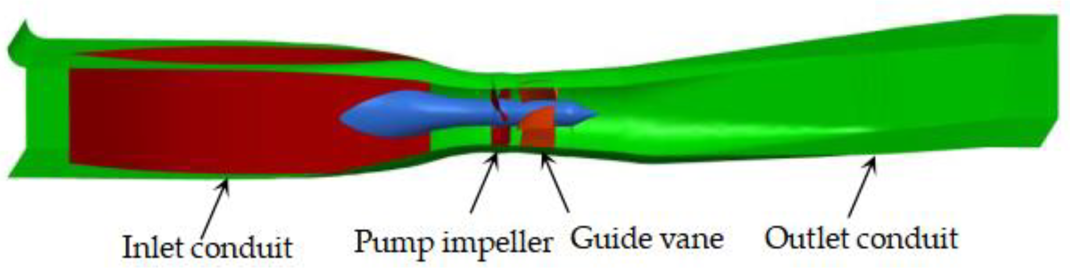
2.1. Shaft Tubular Pump Device Parameters

The parameters of one extra-low head pumping station are as follows: the maximum head, design head, and average head are 2.1 m, 1.33 m, and 0.80 m, respectively; the design flow of a pump is 16.0 m3/s; the pump model is the TJ04-ZL-07 in the test results of the pump model of the South-to-North Water Diversion Project on the same test bench [28]; the prototype pump impeller diameter D p and pump rotation speed n p are 2500 mm and 125 r/min, respectively. The number of impeller blades is 3, the number of guide vane blades is 5, and the specific speed is 1250. The front-positioned shaft tubular pump device is adopted, and the perspective drawing of the pump device is shown in Figure 1.

2.2. Function of the Guide Vane in the Shaft Tubular Pump Device

In the shaft tubular pump device, the guide vane is behind the pump impeller and before the outlet conduit. From the view of hydraulic design, the inlet section of the guide vane carries on the flow from the impeller. Hence, the profile of the inlet section of the guide vane should be designed to ensure a smooth flow of water into the guide vane. The stream flows from the guide vane outlet into the outlet duct, so the shape line design of the outlet section of the guide vane is asked to meet the requirement of the adjusting flow direction. From the structural design, the guide bearing is mounted on the hub of the guide vane, so the guide vane is required to meet the requirement of a fixed guide bearing seat.

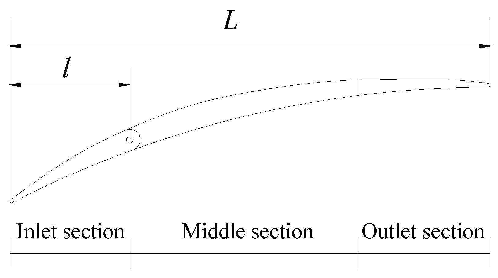
2.3. Adjustment Method of Inlet Section Angle of Guide Vane
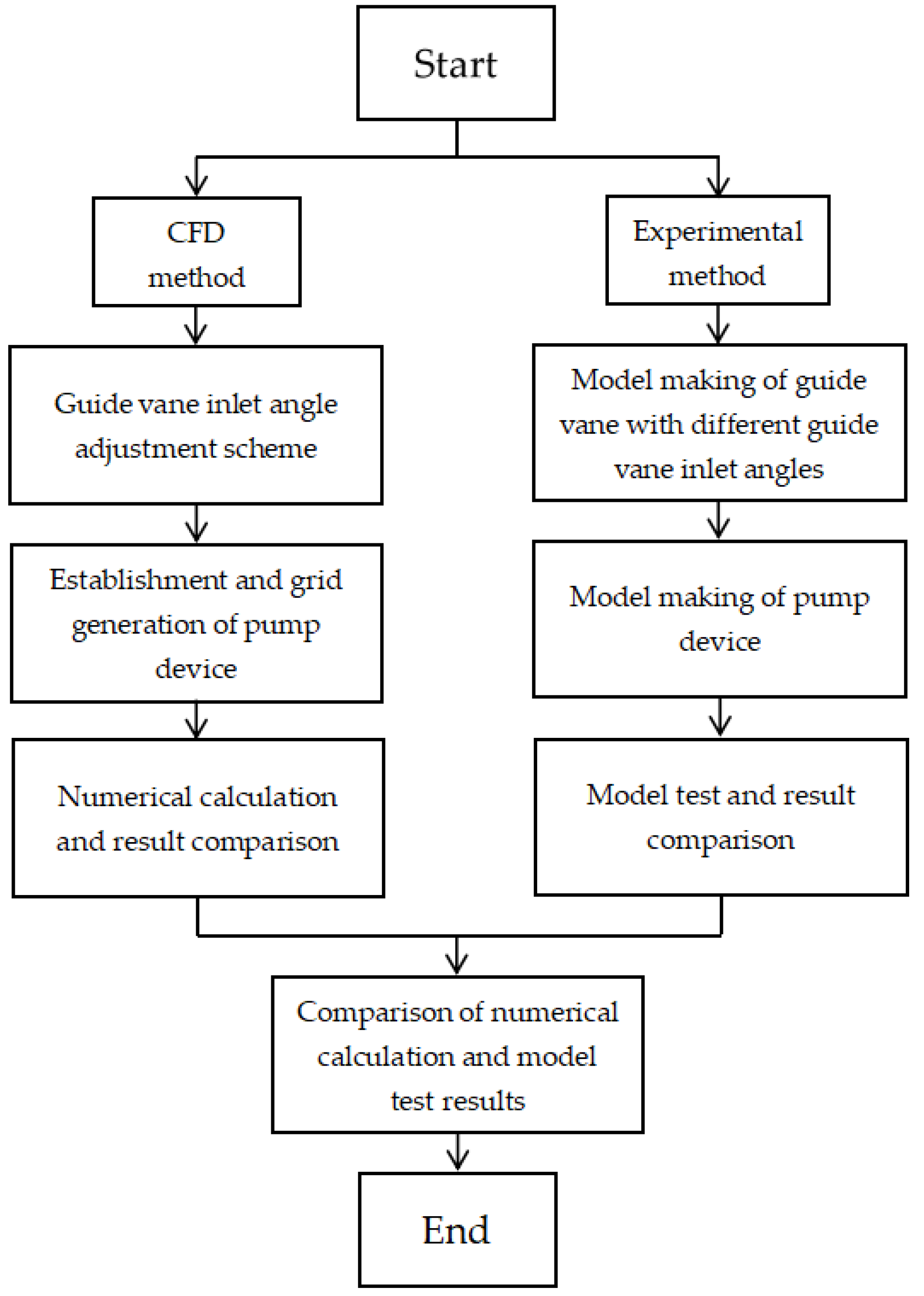
According to the guide vane’s hydraulic design and structural design requirements in the pump device, the guide vane is divided into the inlet section, the intermediate section, and the outlet section (Figure 2). In Figure 2, L is the total length of the guide vane, and l is the length of the inlet section of the guide vane. Among the three sections, the hydraulic design of the inlet section matches the flow direction of the impeller outlet; the hydraulic design of the outlet section is to match the flow field of the outlet conduit; the middle section is to connect the inlet section and outlet section and fix the guide bearing block. In this study, only the angle of the inlet section of the guide vane was adjusted. Considering the supporting function of the guide vane and the influence effect of adjusting the inlet section angle, the l is taken as 0.25 L.
For a well-designed axial-flow pump, the guide vane β 0 inlet angle is in the same direction as the absolute flow velocity at the impeller outlet under the best working conditions (Figure 3a), thus the stream can flow smoothly into the guide vane. If the inlet angle of the guide vane is fixed, when the pump operates in the non-optimal working condition, the inlet angle of the guide vane β 0 will be not matched with the flow direction, then, the flow impact and flow separation will be generated in the guide vane, the hydraulic loss will be increased, and the efficiency will be decreased. To improve the efficiency of the pump device at high flow conditions, deviating from the optimal operating conditions, according to the flow direction at the impeller outlet, the inlet section angle of the guide vane should be rotated clockwise based on β 0 (Figure 3b) so that the stream flows smoothly into the guide vane. For the original guide vane of the pump model, the inlet section angle adjustment Δ β is taken as 0° (the inlet angle of guide vane β 0 ). Based on the research results of the influence of the guide vane inlet angle on the hydraulic performance of an axial-flow pump [19], in order to improve the efficiency under the conditions of large discharge and low head, the guide vane inlet angle needs to be rotated clockwise. For the above shaft tubular pump device in the extra-low head pumping station, according to research results in reference [19] and the design parameters of the pumping station, the inlet angle adjustment Δ β is taken as −12°. Figure 4 shows the perspective drawing of the model pump with the adjustment of the inlet angle Δ β of 0° and −12° when the impeller blade angle α is −2°.
In this study, CFD and experimental methods were used to study the effect of guide vane inlet angle adjustment on the energy performance of the pump device. A flow chart of the main steps for research is shown in Figure 5.

3. Methods

3.1. Numerical Simulation Method

3.1.1. Governing Equations

The numerical simulation of the shaft tubular pump device was carried out by software Fluent 6.3. Steady flow calculations were performed for the pump device in this study. The Reynolds Average Navier–Stokes equations are used for the solution of the flow field in the shaft tubular pump device.
ρ t + ρ u i ¯ x i = 0
ρ u i ¯ t + ρ u i ¯ u j ¯ x j = p ¯ x i + x j [ μ ( u i ¯ x j + u j ¯ x i ) ρ u i u j ¯ ]
where ρ is the density of water; t is time; u i ¯ and u j ¯ are mean velocity components; x i and x j are coordinate directions; F i are the body force components; i , j = 1 , 2 , 3 ; p ¯ is the average pressure; μ is the coefficient of dynamic viscosity.
The water in the pump device is the turbulent flow with a Reynolds number of 9.32 × 10⁶ in the pump under the design discharge condition. A turbulence model is introduced to close the equations; the RNG k ε turbulent model is chosen because it is suitable for solving the rotating flows, separated flows and vortex flows [29,30].
ρ k t + ρ k u i ¯ x i = x j [ ( μ + μ t σ k ) k x j ] + G k ρ ε
ρ ε t + ρ ε u i ¯ x i = x j [ ( μ + μ t σ ε ) ε x j ] + C 1 ε k G k C 2 ε ρ ε 2 k
where k is turbulence kinetic energy; ε is the turbulent kinetic energy dissipation rate, G k is the turbulent kinetic energy production term; C 1 ε and C 2 ε are the empirical constants; σ k and σ ε are the corresponding Prandtl numbers for the turbulent kinetic energy k and the turbulent kinetic energy dissipation rate ε , respectively.

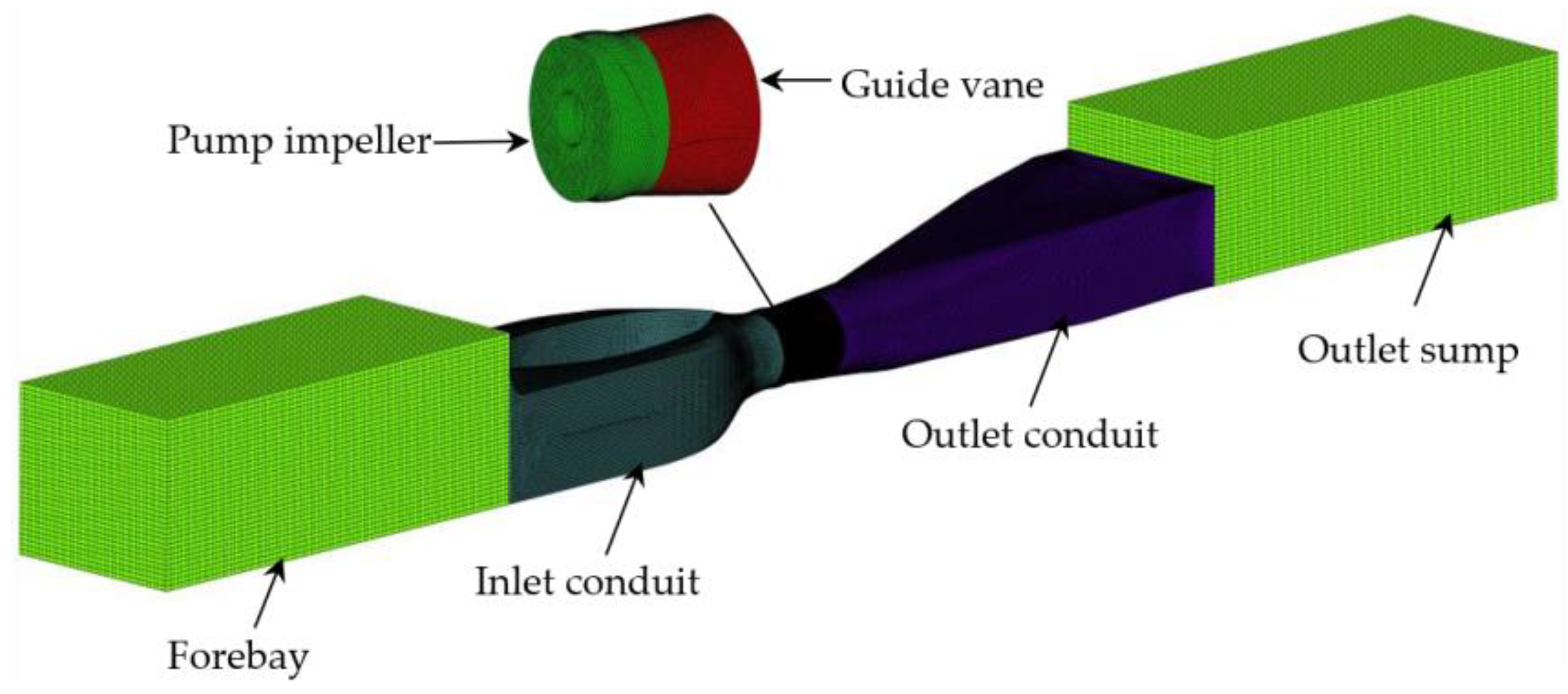
3.1.2. Mesh Generation

The computational domain of the shaft tubular pump device includes a forebay, inlet conduit, an impeller chamber, a guide vane chamber, outlet conduit, and an outlet sump. The unstructured mesh is generated at the inlet conduit, impeller chamber, guide vane chamber, and outlet conduit. The structured mesh is generated at the forebay and outlet sump.
Considering the numerical calculation accuracy and computational amount, grid independence is checked. The pump device heads under different grid numbers are listed in Table 1. It could be found that the pump device head changed slightly when the grid number reached 2,963,731. The grid convergence index (GCI) for the number of grids in this computational domain is 4.45%, satisfying the grid convergence index criterion [31]. It shows that the calculated values of numerical simulations are independent of the number of grids after the number of grids is greater than 2,963,731. The grid numbers of the components of the computational domain are listed in Table 2. The maximum value of y+ in the pump impeller area is 48, which meets the requirement of 30–300 for numerical simulation. The mesh generated at different domains is shown in Figure 6.

3.1.3. Boundary Condition

The boundary condition of the velocity inlet is set on the inlet section of the forebay, the inlet section is far from the inlet conduit entrance, and the velocity distribution on the inlet section is set to be uniform and perpendicular to the inlet section. The boundary condition of outflow is set on the outlet section of the outlet sump. The boundary condition of the solid wall is set on the bottom of the forebay, outlet sump, and the surface of the inlet conduit, outlet conduit, impeller chamber, and guide vane chamber. The boundary condition of the rotation wall is set on the surface of the pump impeller blade. The influence of water level fluctuations in the forebay and outlet sump on the energy performance of the pump device is not considered, thus the symmetry boundary is specified on the surfaces’ forebay and outlet sump.
The inlet boundary of the pump device flow field calculation also needs to set the turbulent flow characteristic parameters, and the turbulent kinetic energy and turbulent kinetic energy dissipation rate are calculated according to the following formulas:
k in = 0.005 u in 2
ε in = c μ k in 3 / 2 l in
where k in is the turbulence kinetic energy at the inlet section; u in is the velocity at the inlet section; ε in is the turbulent kinetic energy dissipation rate at the inlet section; c μ is the empirical constant, 0.085; l in is the characteristic length of the inlet section.
The governing equations are discretized by the finite volume method, the pressure and temperature are coupled by the SIMPLEC method [32], and the convergence precision is set to 1 × 10⁻⁶.

3.2. Model Test Method

3.2.1. Testing System and Model Pump Device

The model test of the front-positioned shaft tubular pump device was conducted on the high-precision pumping station test bench of the Fluid Power Engineering Laboratory of Yangzhou University. Figure 7 is the schematic diagram of the flat closed circulation system of the test bench. The test bench composes of a hydraulic circulation system, a power system, a control system, and a measurement system. The main working parameters of the test bench are as follows: head −1.5~20 m; flow rate 0.05~0.5 m3/s; torque 0~500 N·m; speed 0~2000 r/min. The comprehensive test uncertainty of pump device energy performance is ± 0.316%.
The model front-positioned shaft tubular pump device includes a model inlet conduit, a model pump impeller and impeller chamber, a model guide vane and guide vane chamber, and a model outlet conduit. The model pump device is made of steel plate. The photos of the model front-positioned shaft tubular pump device and test bench are shown in Figure 8.

3.2.2. Testing Scheme

TJ04-ZL-07 is taken as the model pump in the pump device model test, following the law of the same nD value [33] between the prototype pump and model pump. The diameter of the model pump impeller D m is 300 mm, and the rotation speed of the model pump n m is 1041.7 r/min. Consistent with the numerical calculation scheme, the model impeller blade angles α are −2° and 0°, and the model guide vane inlet section angles Δ β are adjusted to 0° and −12°. No less than 15 points are tested per model impeller blade angle in the efficiency test of the pump device.
The model impeller blade angle is adjusted by a rotating blade, but the model guide vane inlet angle is adjusted by using two model guide vanes. The photos of the two model guide vanes are illustrated in Figure 9. The guide vane with the Δ β of 0° is the original guide vane used in TJ04-ZL-07. The guide vane with the Δ β of −12° is a guide vane whose inlet section angle is rotated by 12° counterclockwise, based on the original guide vane.

4. Results and Analysis

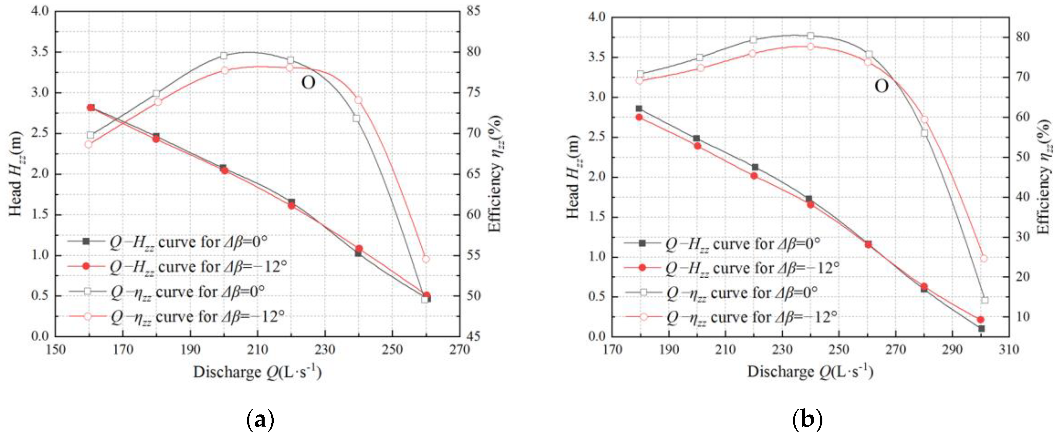
4.1. Numerical Simulation Results and Analysis

Energy performance was numerically calculated by a three-dimensional turbulent flow method in the shaft tubular pump device, for per impeller blade angle, including α of −2° and α of 0°; each inlet section angle adjustment, including Δ β of 0° and Δ β of −12° was matched, respectively, in the guide vane. According to the computational results, the relationships between the flow discharge Q and pump device head H zz , and pump device efficiency η zz are illustrated in Figure 10. The following is analyzed: The Q = f ( η zz ) curves with Δ β of 0° and −12° have an intersection O. When the flow discharge does not reach the discharge of the intersection O, the efficiency of the pump device under Δ β of 0° is higher than the Δ β of −12°. When the flow discharge exceeds the discharge of the intersection O, the efficiency of the pump device under Δ β of 0° is lower than the Δ β of −12°; the farther distance from the intersection O, the larger the difference in pump device efficiency. Compared to the pump device under Δ β of 0°, the efficiency of the optimal point drops by 2% for the pump device under Δ β of −12°. The influence rule of the guide vane inlet angle adjustment on the energy performance of the shaft tubular pump device is consistent with the reference [20].
When the angle of the impeller blade α is 0° and the flow discharge Q is 280 L/s, the flow fields, including the inner ring, middle ring, and outer ring, under the inlet angle adjustments Δ β of 0° and −12° in the guide vane are, respectively, shown in Figure 11a,b. The following is analyzed: when Δ β is 0°, the flow direction in which water enters the guide vane does not match the inlet angle of the guide vane, thus the vortex takes place in front of the guide vane because of flow separation (Figure 11a). Under the large discharge conditions, according to the velocity triangle of the impeller blade outlet (Figure 12), the tangential flow velocity of the water at the impeller outlet is small; the water enters into the guide vane relatively vertically, the inlet angle of the guide vane is inconsistent with the flow direction of the water, and by the inertia of water movement, the water can not flow close to the front of the guide vanes. Thus, the vortex is generated due to flow separation on the front of the guide vane. The guide vane inlet angle should be rotated clockwise to improve the flow pattern, as shown in Figure 3b. When Δ β is −12°, the flow direction of water entering the guide vane matches the guide vane inlet angle, and no vortex is generated in front of the guide vane (Figure 11b). Therefore, the guide vane hydraulic loss is reduced, and the pump device efficiency will be decreased.

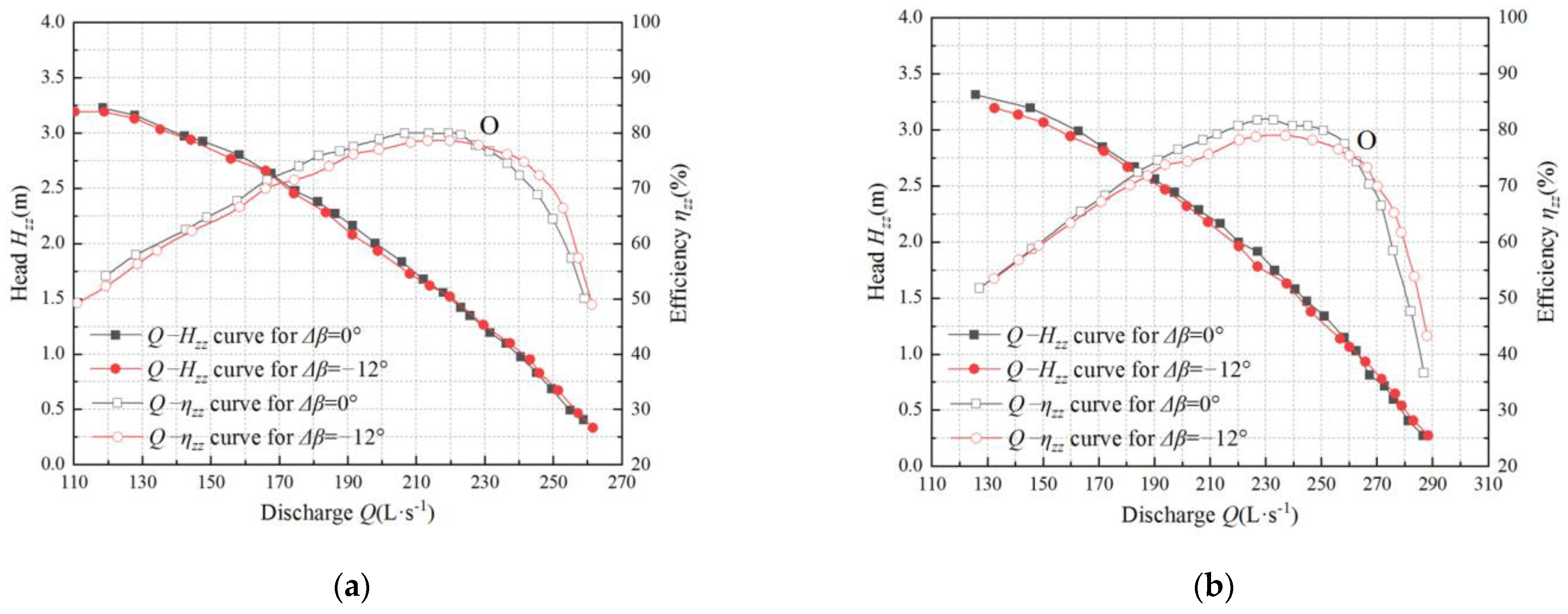
4.2. Experimental Results and Analyses

Based on the experimental results, the relationships between the flow discharge Q and pump device head H zz , and pump device efficiency η zz are illustrated in Figure 13. The main parameters of energy performance under the chosen condition in the pump device are summarized in Table 3 when the inlet section adjustments Δ β are 0° and −12°.
Based on the experimental results of the shaft tubular pump device, the following is concluded: The Q ~ η zz curves with the Δ β of 0° and −12° have an intersection O; the Q and η zz of the intersection O are 227 L/s and 78.6%, respectively, under α of −2°; the Q and η zz of the intersection O are 257 L/s and 76.3%, respectively, under α of 0°. When the Δ β is changed from 0° to −12°, the η zz of the optimal operating condition is decreased; the η zz is, respectively, decreased by 1.6% and 2.2% when the impeller blade angles α are −2° and 0°. When the Q does not reach the discharge of intersection O, the η zz under the Δ β of −12° is higher than that of 0°, and with the decrease of the H zz , the Q gradually increases and the difference of η zz between Δ β of 0° and −12° are more obvious. In the range of working conditions studied in this paper, the pump device efficiency in the low head and large discharge area is increased by 5% at the maximum. When the operating head is 0.8 m, if the inlet section angle is changed from 0° to −12°, the operating efficiency of the shaft tubular pump system under α of −2° and 0° is increased by 2.5% and 1.7%, respectively.

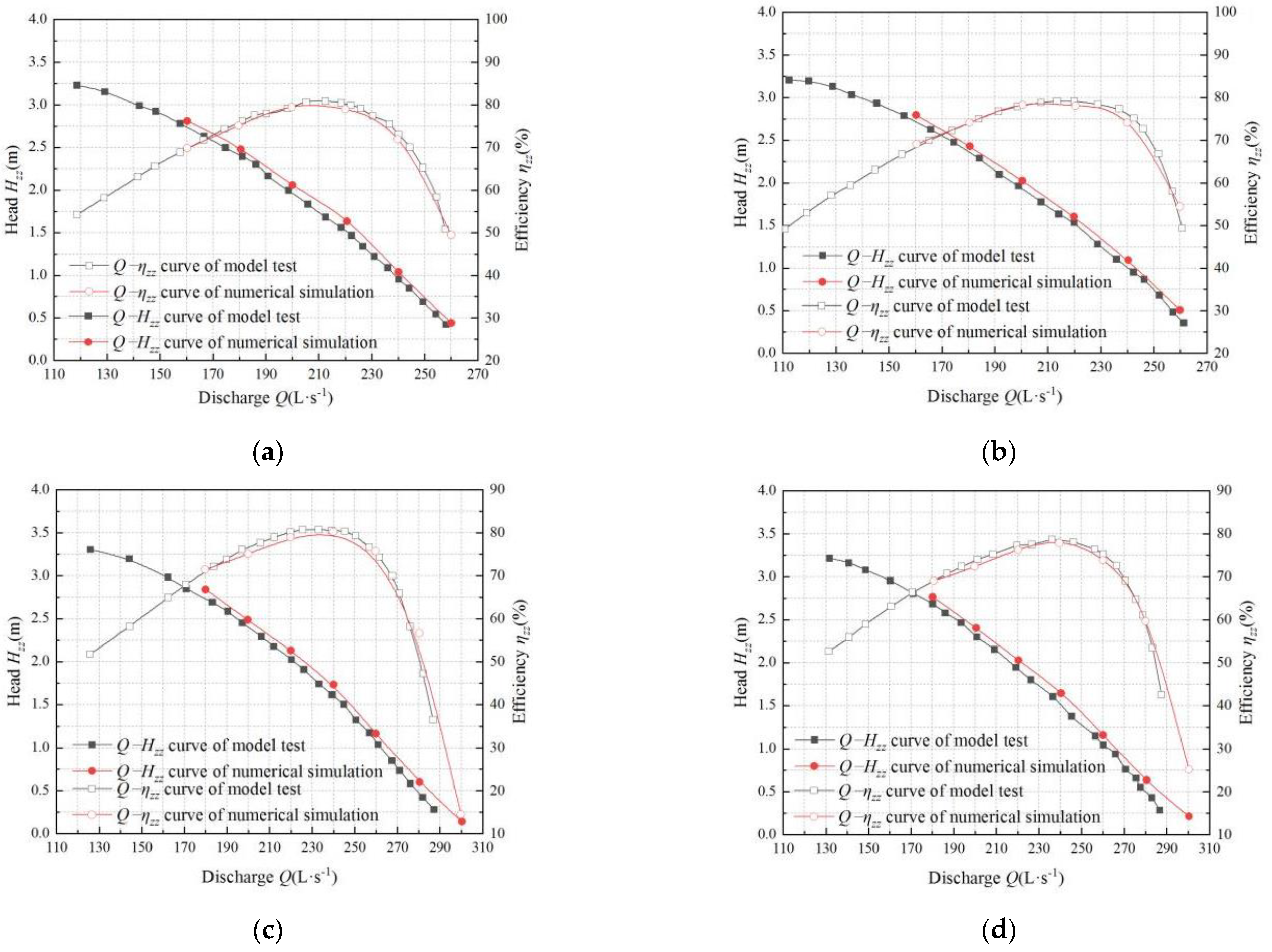
4.3. Comparison of Numerical Simulation and Experimental Results

The comparisons of energy performance between the model test results and numerical calculation results in shaft tubular pump devices under α of −2° and 0° are illustrated in Figure 14. The following is analyzed: Under the same conditions of impeller blade angles and guide vane inlet angles, the variation trends of the flow head curve and flow efficiency curve of the numerical simulation are the same as that of the model test; the numerical calculation results agree well with the model test results. The error of η zz is small in the small discharge area and large in the large discharge area; the maximum difference of η zz is within 7%, and the maximum difference of H zz is within 0.15 m.

5. Conclusions

The energy performance of the front-positioned shaft tubular pump device at two guide vane inlet angles was compared using the methods of numerical simulation and a model experiment, thus obtaining the following conclusions:
(1)
The energy performance of the front-positioned shaft tubular pump device is affected obviously by the inlet section angle adjustment of the guide vane. When the inlet section angle of the guide vane is adjusted clockwise, the efficiency of the pump device at the optimum operating point is reduced, while the efficiency of the pump device on the condition of low head and large discharge, which deviates from the optimum operating point, will be improved. The farther the operating condition deviates from the optimal operating point, the greater the influence. When the inlet section of the guide vane is rotated from 0° to −12°, the efficiency of the pump device at the optimum operating point is reduced by about 2%, and the efficiency of the pump device in the condition of low head and large discharge is increased by more than 5%.
(2)
When the inlet section of the guide vane is adjusted clockwise, the inlet section angle of the guide vane will match the pump impeller outlet flow direction under the operating condition of low head and large discharge, so that the stream will enter the guide vane smoothly without vortex. The improvement of the flow pattern in the guide vane will lead to a reduction in the hydraulic loss of the guide vane; thereby, the efficiency of the pump device is increased.
(3)
Comparing the numerical calculation and model test results of the efficiency of the pump device, the error is small in the small discharge area and large in the large discharge area, the maximum error of the efficiency of the pump device is less than 7%, and the maximum error of the pump device head is less than 0.15 m. It shows that the numerical calculation results are in good agreement with the model test results, and the numerical calculation results can provide a good guide for the hydraulic design of the shaft tubular pump device.
(4)
Due to the limitation of the pump model or motor product, the frequent operating condition of the extra-low head pumping station often deviates from the optimal operating condition. The frequent operating condition is located in the area of large discharge and low head, and the operating efficiency of the pump station is low. Applying these research results can improve its energy performance and reduce operating costs.

Author Contributions

Conceptualization, L.X. and L.L.; methodology, L.X. and L.L.; software, L.X. and F.L. (Fusheng Lv); validation, W.L. and W.S.; investigation, L.X. and D.J.; data curation, L.X., F.L. (Fusheng Lv), and D.J.; project administration, L.L.; supervision, W.S. and W.L.; visualization, F.L. (Fusheng Lv), F.L. (Feifan Li), and D.J.; writing—original draft preparation, L.X.; writing—review and editing, L.X., L.L.; funding acquisition, W.S. All authors have read and agreed to the published version of the manuscript.

Funding

This research was funded by the National Natural Science Foudation of China (Grant No. 51309200, Grant No. 51779215), Jiangsu South-to-North Water Diversion Technology R&D Project (JSNSBD202105).

Institutional Review Board Statement

Not applicable.

Informed Consent Statement

Not applicable.

Data Availability Statement

Not applicable.

Conflicts of Interest

The authors declare no conflict of interest.

Nomenclature

symbolExplanation
c μ Empirical constant
C 1 ε Empirical constant
C 2 ε Empirical constant
D m Model pump impeller diameter
D p Prototype pump impeller diameter
G k Turbulent kinetic energy production term
H zz Pump device head
lInlet section length of guide vane
l in   Characteristic length of the inlet section
LTotal length of guide vane
n m Model pump rotation speed
n p Prototype pump rotation speed
p ¯ Average pressure
Q Flow discharge
t Time
u i ¯ Mean velocity component in i direction
u j ¯ Mean velocity component in j direction
u in Velocity at the inlet section
x i Coordinate in i direction
x j Coordinate in j direction
α Impeller vane angle
β 0 Guide leaf inlet angle
Δ β Inlet section angle adjustment of guide vane
ε Turbulent kinetic energy dissipation rate
ε in Turbulent kinetic energy dissipation rate at the inlet section
η zz Pump device efficiency
k Turbulence kinetic energy
k in Turbulence kinetic energy at the inlet section
μ Coefficient of dynamic viscosity.
ρ Density of water
σ k Prandtl   numbers   for   k
σ ε Prandtl   numbers   for   ε

References

  1. Dai, Y.; Tang, K. Experimental study on hydraulic characteristics of ultra low dead vertical crosswise pump unit. Heilongjiang Hydraul. Sci. Technol. 2016, 49, 66–69. [Google Scholar]
  2. Yu, J.; Chen, Y.; Zhu, Y.; Lv, B.; Sun, P. Study on pump type selection for extra-low head pumping station with large difference between average and highest heads. Water Resour. Hydropower Eng. 2018, 49, 68–76. [Google Scholar]
  3. Wu, H.; Tian, Y.; Liao, W.; Liu, B.; Song, W. Pumping device performance analysis based on the Miyun Storage Project of Cascade Pumping Stations. China Rural. Water Hydropower 2016, 11, 178–182. [Google Scholar]
  4. Xia, B. Research on the Application of Vertical Pump Device in Extra-low Head Drainage Pumping Station. M.E. Thesis, Yangzhou University, Yangzhou, China, 2021. [Google Scholar]
  5. Tang, F.; Wang, G. Influence of outlet guide vanes upon performances of waterjet axial-Flow Pump. J. Ship Mech. 2006, 6, 19–26. [Google Scholar]
  6. Li, Z.; Yang, M.; Wang, X. Experimental study of guide vane influence on performance of axial-flow pump. Drain. Irrig. Mach. 2009, 27, 15–18. [Google Scholar]
  7. Kaya, D. Experimental study on regaining the tangential velocity energy of axial fow pump. Energy Convers. Manag. 2003, 44, 1817–1829. [Google Scholar] [CrossRef]
  8. Hu, J.; Huang, S.; Wang, P. Research on hydrodynamic characteristics of axial waterjet pump with guide vane. J. Hydroelectr. Eng. 2008, 27, 32–36. [Google Scholar]
  9. Zhou, Y.; Xu, H. The influence of diffuser on the function of the axial-flow pump. Water Conserv. Electr. Power Mach. 2007, 29, 28–29. [Google Scholar]
  10. Qian, Z.; Wang, Y.; Zheng, B.; Liu, D. Numerical simulation and analysis of performance of axial flow pump with adjustable guide vanes. J. Hydroelectr. Eng. 2011, 30, 123–127. [Google Scholar]
  11. Qian, Z.; Wang, Y.; Huai, W.; Lee, Y. Numerical simulation of water flow in an axial flow pump with adjustable guide vanes. J. Mech. Sci. Technol. 2010, 24, 974–976. [Google Scholar] [CrossRef]
  12. Qian, Z.; Wang, F.; Wang, Z.; Zhou, W. Experimental study on hydraulic performance of saddle zone in axial-flow pump with adjustable guide vane. J. Drain. Irrig. Mach. Eng. 2013, 31, 461–465. [Google Scholar]
  13. Yan, T.; Liu, C.; Zha, Z.; Huang, J. Influence of installation angle of guide-vane inlet on axial flow pump performance. Water Resour. Hydropower Eng. 2018, 49, 72–77. [Google Scholar]
  14. Li, G.; Chen, E.; Yang, A.; Xie, Z.; Zhao, G. Effect of guide vanes on flow and vibroacoustic in an axial-flow pump. Math. Probl. Eng. 2018, 2018, 3095890. [Google Scholar] [CrossRef]
  15. Yang, F.; Zhao, H.; Liu, C. Improvement of the efficiency part loads due to installing outlet. Math. Probl. Eng. 2016, 2016, 6375314. [Google Scholar]
  16. Zhu, H.; Zhang, R. Numerical simulation of internal flow and performance prediction of tubular pump with adjustable guide vanes. Adv. Mech. Eng. 2014, 6, 171504. [Google Scholar] [CrossRef]
  17. Feng, J.; Zheng, Y.; Luo, X. Effects of exit guide vane on performance of axial-flow pump system. Water Resour. Power 2012, 30, 126–129. [Google Scholar]
  18. Liang, J.; Lu, L.; Xu, L.; Chen, W.; Wang, G. Influence of flow velocity circulation at guide vane outlet of axial-flow pump on hydraulic loss in outlet conduit. Trans. CSAE 2012, 28, 55–60. [Google Scholar]
  19. Xu, L.; Ji, D.; Shi, W.; Xu, B.; Lu, W.; Lu, L. Influence of inlet angle of guide vane on hydraulic performance of an axial flow pump based on CFD. Shock. Vib. 2020, 2020, 8880789. [Google Scholar] [CrossRef]
  20. Xu, L.; Zhang, H.; Wang, C.; Ji, D.; Shi, W.; Lu, W.; Lu, L. Hydraulic characteristics of axial flow pump device with different guide vane inlet angles. Front. Energy Res. 2022, 10, 836456. [Google Scholar] [CrossRef]
  21. Pei, J.; Meng, F.; Li, Y.; Yuan, S.; Chen, J. Effects of distance between impeller and guide vane on losses in a low head pump by entropy production analysis. Adv. Mech. Eng. 2016, 8. [Google Scholar] [CrossRef] [Green Version]
  22. Kang, L.; Bu, G.; Zhang, J. Type selection of Daxigang Drainage Pumping Station structure in Wuxi Taihu New City. China Water Wastewater 2013, 29, 14–17. [Google Scholar]
  23. Xu, L.; Lu, L.; Chen, W.; Wang, G. Flow pattern analysis on inlet and outlet conduit of shaft tubular pump system of Pizhou pumping station in South-to-North Water Diversion Project. Trans. Chin. Soc. Agric. Eng. 2012, 28, 50–56. [Google Scholar]
  24. Pranav, V.; Lokavarapu, B.R.; Nilesh, P. CFD analysis of double suction centrifugal pump with double volute. Period. Polytech. Mech. Eng. 2018, 62, 74–82. [Google Scholar]
  25. Grzegorz, P.; Piotr, W.; Andriy, Z. Experimental and numerical studies on the influence of blade number in a small water turbine. Energies 2021, 14, 2604. [Google Scholar]
  26. Liu, Y.; Zhou, J.; Guo, Q.; Shen, A.; Zhang, J. 3-D CFD simulation of transients in multiple pump system with some pumps being stopped. J. Hydrodyn. 2021, 33, 583–592. [Google Scholar] [CrossRef]
  27. Daniel, A.; Du, J.; Ransford, O.D.; Eric, O.A.; Muhammad, A.S.K. Numerical and experimental characterization of splitter blade impact on pump as turbine performance. Sci. Prog. 2021, 104. [Google Scholar] [CrossRef]
  28. Liu, N.; Wang, Y.S.; Zhang, G. Model Pump Test on the Same Test-Bed for the South-to-North Water Diversion; China Water Power Press: Beijing, China, 2006. [Google Scholar]
  29. Shi, L.; Yuan, Y.; Jiao, H.; Tang, F.; Cheng, L.; Yang, F.; Jin, Y.; Zhu, J. Numerical investigation and experiment on pressure pulsation characteristics in a full tubular pump. Renew. Energy 2021, 163, 987–1000. [Google Scholar] [CrossRef]
  30. Ramirez, R.; Avila, E.; Lopez, L.; Bula, A.; Duarte Forero, J. CFD characterization and optimization of the cavitation phenomenon in dredging centrifugal pumps. Alex. Eng. Jouranl 2020, 59, 291–309. [Google Scholar] [CrossRef]
  31. Liu, H.; Liu, M.; Bai, Y.; Du, H.; Dong, L. Convergence of centrifugal pump meshes based on GCI. J. Jiangsu Uinversity Nat. Sci. Ed. 2014, 35, 279–283. [Google Scholar]
  32. Wang, F. Computational Fluid Dynamics Analysis–Principle and Application of CFD Software; Tsinghua University Press: Beijing, China, 2004; pp. 83–91. [Google Scholar]
  33. Liang, J.; Lu, L.; Xu, L.; Chen, W. Selection of nD value of large low lift pump device. J. Drain. Irrig. Mech. Eng. 2011, 29, 236–240. [Google Scholar]
Figure 1. Perspective drawing of the shaft tubular pump device.
Processes 10 01054 g001
Figure 2. Schematic diagram of guide vane subsection.
Processes 10 01054 g002
Figure 3. The turn direction of guide vane inlet angle. (a) Inlet angle of guide vane ( Δ β = 0), (b) clockwise rotation ( Δ β < 0).
Processes 10 01054 g003
Figure 4. Perspective drawing of model pump with α of −2°, (a) Δ β = 0°, (b) Δ β = −12°.
Processes 10 01054 g004
Figure 5. Flow chart of the main steps for research.
Processes 10 01054 g005
Figure 6. Computational domain and mesh generation of the shaft tubular pump device.
Processes 10 01054 g006
Figure 7. Schematic diagram of the flat closed circulation system of the test bench.
Processes 10 01054 g007
Figure 8. Photo of the model shaft tubular pump device.
Processes 10 01054 g008
Figure 9. Photos of model guide vanes, (a) Δ β = 0°, (b) Δ β = −12°.
Processes 10 01054 g009
Figure 10. Comparison of energy performance under Δ β of 0° and −12° in pump device, (a) α = −2°, (b) α = 0°.
Processes 10 01054 g010
Figure 11. Flow fields of guide vane with Δ β of 0° and −12°, (a) Δ β = 0°, (b) Δ β = −12°.
Processes 10 01054 g011
Figure 12. Velocity triangle of impeller blade outlet under large discharge condition.
Processes 10 01054 g012
Figure 13. Comparison of energy performance under Δ β = 0° and Δ β = −12° in pump device, (a) α = −2°, (b) α = 0°.
Processes 10 01054 g013
Figure 14. Comparisons of energy performance between model test and numerical calculation results in pump device: (a) α = −2°, Δ β = 0°, (b) α = −2°, Δ β = −12°, (c) α = 0°, Δ β = 0°, (d) α = 0°, Δ β = −12°.
Processes 10 01054 g014
Table 1. Pump device heads under different grid numbers.
Grid Number1,285,6111,694,7452,240,2412,963,7313,885,808
Pump device head (m)1.611.671.721.741.75
Table 2. Grid numbers of each calculation domain.
Computational DomainForebayInlet ConduitPump ImpellerGuide VaneOutlet ConduitOutlet SumpTotal
Grid numbers370,5901020,569541,245685,722295,35550,2502,963,731
Table 3. The energy performance parameter under Δ β of 0° and −12° in the shaft tubular flow pump device.
α Δ β Optimal Working Condition of Pump Device Intersection   O   of   the   Q ~ η zz   with   Δ β   of 12 °   and   0 °
Q   ( L / s ) H zz   ( m ) η zz   ( % ) Q   ( L / s ) H zz   ( m ) η zz   ( % )
−2°2121.6980.72271.3578.6
−12°2141.6479.1
2331.7480.82571.1676.3
−12°2361.6278.6
Publisher’s Note: MDPI stays neutral with regard to jurisdictional claims in published maps and institutional affiliations.

