Article

Development of a ZrO2-Coating Technique by a Sol–Gel Process Assisted with Pre-Silica-Coating

1
Department of Materials Science and Engineering, Graduate School of Science and Engineering, Ibaraki University, Ibaraki 316-8511, Japan
2
Central Research Institute, Mitsubishi Materials Corporation, Ibaraki 311-0102, Japan
*
Author to whom correspondence should be addressed.
Processes 2022, 10(11), 2217; https://doi.org/10.3390/pr10112217
Submission received: 14 September 2022 / Revised: 24 October 2022 / Accepted: 25 October 2022 / Published: 27 October 2022

Abstract

:

Highlights

We propose a method for ZrO2-coating a ceramic substrate using a sol–gel process. The ZrO2 film was not damaged, even after annealing at 600 °C in air. Pre-SiO2 coating on the substrate was performed with a sol–gel reaction of tetraethoxysilane. The pre-SiO2 coating increased the affinity between the ZrO2 film and the substrate. As a result, thick ZrO2 films formed on the substrate.

Abstract

The development of techniques for coating thermistors with materials possessing excellent chemical resistance and electrical insulation characteristics is necessary to ensure their protection. The present work proposes a coating technique using zirconia (ZrO2), which has excellent chemical resistance and electrical insulation properties, based on initiating a sol–gel reaction of zirconium alkoxide in the presence of a ceramic substrate consisting of the common components of thermistors. The ZrO2 films on substrates were not damaged, even after annealing at 600 °C in air. Several ZrO2 particles were also deposited on the substrate. Pre-silica (SiO2)-coating the substrate, which was performed through a tetraethoxysilane (TEOS) sol–gel reaction, decreased the amount of ZrO2 particles and promoted the formation of thick ZrO2 films, as the reaction between the Zr butoxide and the alkoxyl groups of incompletely hydrolyzed TEOS on the substrate increased the affinity between the ZrO2 layer and the substrate.

Graphical Abstract

1. Introduction

Various electronic devices, including electro-conductors, semiconductors, and electrical insulators, are indispensable in various fields, such as electronics and optics [1,2,3], and are pervasive in everyday life. Thermistors are one such type of device, and ceramics including Mn, Fe, Co, Ni, etc., are used for their design and construction [4,5,6]. It is hard to maintain their properties, as they are damaged by oxidation in the air, and this damage is accelerated by severe oxidation caused by exposure to high temperatures [7,8].
The coating of thermistors with materials possessing excellent chemical resistance and electrical insulation characteristics provides a technique to solve the abovementioned problem, as the coating controls the contact of the thermistor with oxygen. Ceramics such as silica (SiO2), alumina, and zirconia (ZrO2) are typical examples of coating materials with excellent chemical resistance properties [9,10,11]. Among them, ZrO2 is expected to function as an effective coating material, due to its excellent chemical resistance and thermal insulation properties [12,13]. Apart from these properties, the ZrO2 is as tough and/or mechanically stable as many other ceramics [14,15,16], contributing to its coating potential.
Methods for ZrO2-coating can be broadly classified into gas-phase methods, including chemical vapor deposition and physical vapor deposition [17,18], and liquid-phase methods [19,20]. Instruments for the gas-phase methods are expensive and complicated to operate, as they usually require a vacuum system. Liquid-phase methods are suitable for industrial and practical coating, as such methods make it possible to coat a wide area of substrate easily at low cost. Many studies on ZrO2-coating using a sol–gel method—one of the liquid phase methods—have been reported [11,21,22,23,24]. Zr alkoxide, which is often used as a starting material, reacts with water. As a result, many zirconium (Zr) oxide nuclei are produced in the solution, leading to the formation of a film on the substrate. Generally, the reaction proceeds quite intensively, facilitating the formation of a porous film, instead of a dense film on the substrate. However, the formation of a porous film may lead to exposure of the ceramics, resulting in their damage and possibly creating problems.
Controlling the rate of the sol–gel reaction has been considered as a candidate process for solving the abovementioned problem. From this perspective, the present work addresses three key aspects for the purpose of fabricating a uniform and dense ZrO2 film: First, we propose a process for ZrO2-coating, in which ZrO2 is produced in a reaction solution containing a substrate. Second, we investigate the effects of the reaction conditions for the production of ZrO2 on the morphology of the produced film. Third, we finely optimize the reaction conditions, in which the generation of ZrO2 precursor nuclei, deposition of the nuclei on a substrate, and growth of nuclei on the substrate are controlled and are all performed in one step.
As ZrO2 possesses oxide surfaces, it should have a strong affinity with other oxide surfaces. SiO2 also has oxide surfaces, and is easily and simply fabricated. Therefore, the idea of the use of a pre-SiO2-coated substrate as a substrate for ZrO2-coating was developed. Therefore, in the present work, the effect of pre-SiO2-coating on the morphology of the formed ZrO2 film was also studied for the purpose of improving the affinity between the ZrO2 film and substrate.

2. Experimental

2.1. Materials

The substrate used in the present work was a ceramic composed mainly of manganese oxide, iron oxide, cobalt oxide, and copper oxide, with similar components to those of conventional thermistors, as shown in Figure 1a, and was supplied by Mitsubishi Materials Co. Ltd. Figure 1b,c show SEM images of the substrate surfaces obtained by dicing and slicing, respectively. The surfaces obtained by dicing and slicing appeared relatively smooth and uneven, respectively. Figure 1d shows the XRD pattern of the substrate. Peaks were detected at 30.3, 35.7, 43.3, 47.3, and 63.0 degrees, which were attributed to the (220), (311), (400), (511), and (440) planes of γ-Fe2O3 (cubic), respectively, according to ICDD code (#00-039-1346). Accordingly, one component of iron was crystalline, while other components were amorphous or too fine to be detected by XRD. Tetraethoxysilane (TEOS) (Kanto Chemical, 95%), ethanol (Kanto Chemical, 99.5%), and sodium hydroxide (NaOH) aqueous solution (Kanto Chemical, 1 M) were used for pre-SiO2-coating, as the SiO2 source, solvent of the TEOS solution, and an initiator of the TEOS sol–gel reaction, respectively. Zr (IV) tetrabutoxide (ZTB) (Wako, 85% in 1-butanol) and methylamine (Kanto Chemical, 38–42% in water) were used for ZrO2-coating, as the ZrO2 source and initiator of the ZTB sol–gel reaction, respectively. 1-Butanol and acetonitrile were used as solvents for the ZTB solution. All chemicals were used as received. Deionized and distilled water, which was used for all preparations, was prepared using an Advantec RFD372NC water distillation apparatus.

2.2. Preparation

2.2.1. Pre-SiO2-Coating

The substrate was put into a mixture of TEOS, ethanol, and water. To pre-coat an SiO2 film on the substrate, the TEOS sol–gel reaction was initiated by the addition of NaOH aqueous solution to the mixture under stirring at 35 °C. The initial concentrations of TEOS, NaOH, and H2O in the final TEOS/ethanol solution were 5.0 × 10⁻³, 8.3 × 10⁻⁴, and 5.0 × 10⁻² M, respectively. Then, the pre-SiO2 film on substrate was washed by rinsing the pre-coated substrate with ethanol. Pre-SiO2-coating and washing were repeated several times to obtain multi-layer SiO2 films.

2.2.2. ZrO2-Coating

The substrate was put into a mixture of ZTB, 1-butanol, and acetonitrile. To form a ZrO2 precursor film on the substrate, the ZTB sol–gel reaction was initiated with the addition of H2O/methylamine solution to the mixture under stirring at 35 °C. The initial concentrations of ZTB, methylamine, and H2O in the final ZTB/acetonitrile/1-butanol solution were 5.0 × 10⁻³, 8.3 × 10⁻⁴, and 5.0 × 10⁻² M in 50% (v/v) acetonitrile/1-butanol, respectively. The film formed on the substrate was washed by rinsing the substrate with 1-butanol. The formation and washing steps were repeated several times to obtain multi-layer ZrO2 films. The precursor film was annealed in air for crystallization. As the precipitate produced in the solution during film formation was considered to be the same material as the film on substrate, the powder derived from the precipitate was also characterized.

2.2.3. ZrO2-Coating on Pre-SiO2-Coated Substrate

The pre-SiO2-coated substrates were also used for ZrO2-coating (SiO2/ZrO2). The ZrO2-coating process was the same as described above, except with pre-SiO2-coated substrate as the substrate for ZrO2-coating.

2.3. Characterization

The samples were characterized by XRD, scanning electron microscopy (SEM), energy dispersive X-ray spectrometry (EDX), and XPS. The XRD measurements were carried out using a Rigaku Ultima IV X-ray diffractometer with a CuKα radiation source operated at 40 kV and 30 mA. The XRD samples were the substrate and powders of the particles. The particles in the colloidal solution were washed by repeated centrifugation and decantation to remove the supernatant, followed by the addition of water and redispersion by shaking using a vortex mixer. The washing process was performed three times, and the particle powder was obtained by centrifuging the colloidal solution, removing its supernatant by decantation in the third washing process and drying the slightly wet particle powder in a Yamato DP-31 vacuum-drying oven equipped with an oil-sealed rotary vacuum pump (ULVAC GCD-136X). SEM was carried out using a Hitachi SU5000 scanning-electron microscope operating at 15 kV. Elemental analysis of the EDX profiles was performed using a Hitachi SU5000 equipped with an EDX analyzer. The acceleration voltage of the SEM during EDX analysis was 15 kV. The samples for EDX were prepared through the dropwise addition of the colloidal particle solution onto a metallic copper stage. XPS was performed using a JEOL JPS-9010 equipped with a monochromatic Mg Kα radiation source (200 W, 10 kV, 1253.6 eV). To determine the composition of the films in the depth direction, the films on substrates were treated with an etching process by Ar+ sputtering at 500 kV. Etching was performed for 10 s for each etching process.

3. Results and Discussion

3.1. Product Obtained from the ZTB Sol–Gel Reaction

The precipitate produced in the aqueous solution during film formation was colored white. Figure 2 shows the XRD patterns of precipitate powders annealed at various temperatures. The XRD pattern of the as-prepared precipitate powder is also shown. No dominant peaks were detected for the as-prepared precipitate and the precipitates annealed at 100–300 °C, indicating that these precipitates were amorphous or too fine to be detected by XRD. Peaks appeared at 30.3, 35.3, 50.3, 50.8, 59.5, 60.2, and 63.1 degrees after annealing at 400 °C, attributed to the (101), (110), (112), (200), (103), (211), and (202) planes of tetragonal ZrO2 (t-ZrO2), respectively, according to [25,26] and international center for diffraction data (ICDD) code #00-002-0733. The t-ZrO2 peaks were intensified with an increase in annealing temperature of up to 500 °C, as annealing accelerated the crystallization of ZrO2. The t-ZrO2 peaks were weakened with an increasing annealing temperature of up to 600 °C. Instead, the peaks appeared at 24.1, 28.2, 31.5, 34.2, 40.7, and 55.4 degrees, attributed to the (110), ( 1 ¯ 11), (111), (020), (102), and (130) planes of monoclinic ZrO2 (m-ZrO2), respectively, according to references [25,26] and ICDD code #00-1-0750. Accordingly, the t-ZrO2 began to transform to m-ZrO2 at 600 °C. Pure ZrO2 is m-ZrO2 at room temperature and is transformed to t-ZrO2 with annealing at ca. 1100 °C, as has been mentioned by several researchers [27,28,29]. A phase diagram established by Bouvier et al. clearly indicates that compressive stress stabilizes t-ZrO2 [30]. Tensile stress and shear stress are the primary driving forces to trigger the transformation from t-ZrO2 to m-ZrO2 [31]. Gao et al. have found that anionic impurities, such as OH, had effects on the crystalline conversion; that is, the existence of residual hydroxyl groups contained in the ZrO2 that form zirconium hydroxide may be a major factor in the generation of t-ZrO2 rather than m-ZrO2 at low temperatures [32]. In the present work, such anionic impurities should have been contained in the particles, and the dehydration derived from the sol–gel reaction more or less exerted the compressive stress on the particles. Then, annealing condensed the residual hydroxyl groups to form Zr–O–Zr bonds or ZrO2, which generated the tensile stress and shear stress in particles. The effect of anionic impurities and the generation of stresses probably favored the system in which the t-ZrO2 was produced, and then the transformation from t-ZrO2 to m-ZrO2 occurred.

3.2. Pre-SiO2-Coating
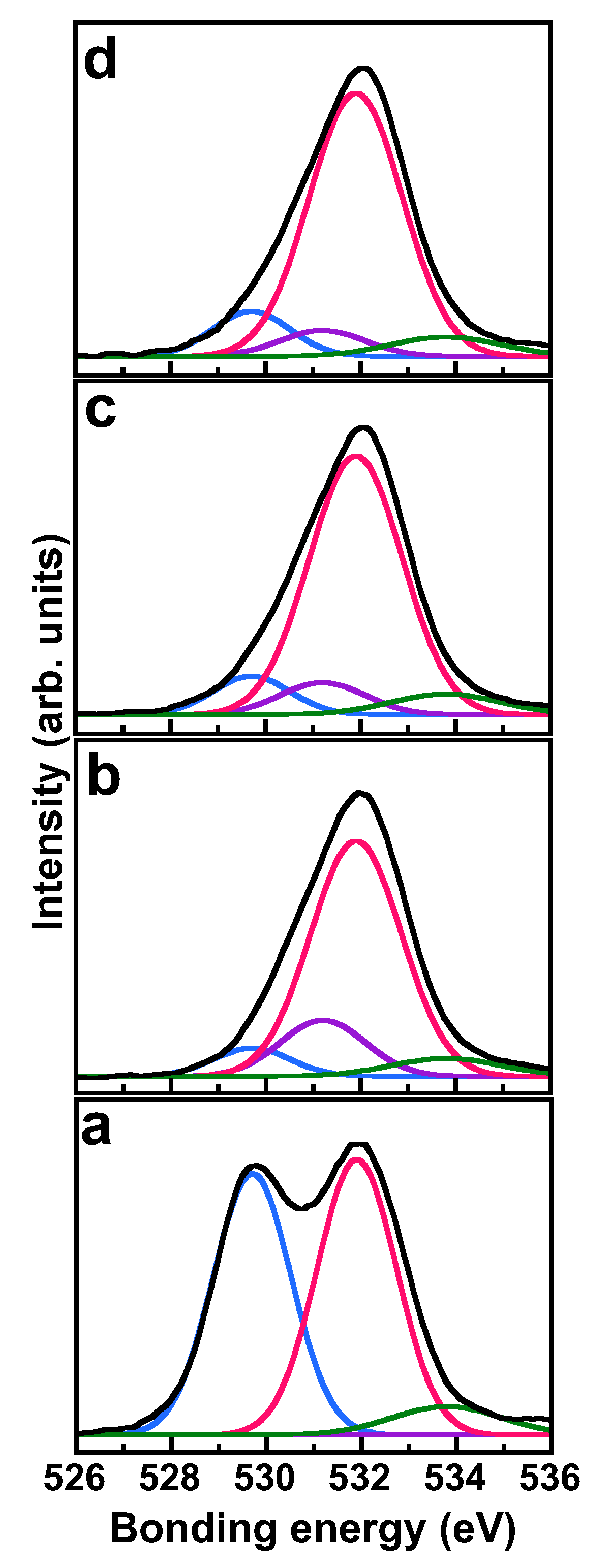
Figure 3a shows an SE image of the cross-section of the SiO2-coated substrate. The cross-section and surface of SiO2-coated substrate can be observed as the lower and upper halves, respectively. As the sample was placed such that the cross-section was horizontal to the image (i.e., such that the surface moves away as the eye moves up the image), the image appears out of focus with such eye movement. Figure 3b shows an elemental map of silicon (Si) in the cross-section of the substrate after pre-SiO2-coating. Si was only distributed on the substrate, and almost uniformly. This Si was absolutely derived from the SiO2. Accordingly, the substrate was found to be uniformly coated with SiO2.

3.3. ZrO2-Coating

If ZrO2-coating parameters that provide a good coating under severe conditions for the ZrO2 film can be found, the objective of this study will almost have been achieved. As the transition from t-ZrO2 to m-ZrO2, which was detected in the particles, is a change accompanying volume expansion, cracks may form on the substrate surface after annealing. This cracking should correspond to severe conditions for the ZrO2 film. Thus, the effect of the transition accompanying volume expansion on film morphology was investigated, particularly when the annealing temperature was adjusted to 600 °C, at which point the t-ZrO2 began to be transformed into m-ZrO2, as seen in Figure 2. All ZrO2-coated substrates were annealed at 600 °C after the coating, in order to crystallize the ZrO2 films onto the substrate, as the transformation to m-ZrO2 took place at 600 °C, according to the XRD measurements for the product obtained by the sol–gel reaction of ZTB shown in Figure 2.
Figure 4(a1) shows an SEM image of surface of the ZrO2-coated substrate, where the ZrO2-coating process was carried out once. Several ZrO2 particles produced by the sol–gel process were present on the coated substrate surface. Figure 4(a2) shows an SEM image of a cross-section of ZrO2-coated substrate. No film could be identified with SEM, due to the small film thickness and SEM resolution. Figure 4(b1) shows an SEM image of the surface of the ZrO2-coated substrate after three rounds of ZrO2-coating. Several ZrO2 particles produced by the sol–gel process can be seen to be present on the coated substrate surface. Figure 4(b2) shows an SEM image of a cross-section of ZrO2-coated substrate, from which the presence of the ZrO2 film can be confirmed. The obtained films appeared dense even after annealing. In addition, the film was not peeled off the substrate, which indicated that the film had excellent adhesion and coating properties. The lack of effect of the transition was due to the stress generated by volume expansion being controlled, as a result of the removal of the impurities inside the films.
Figure 4(c1) shows an SE image of a cross-section of ZrO2-coated substrate, in which the ZrO2-coating process was performed three times. The cross-section and the surface of the ZrO2-coated substrate were observed on the lower and upper halves. The image appears out of focus with the bottom-to-top eye movement, as in Figure 3. Figure 4(c2) shows an elemental map of Zr in the cross-section of ZrO2-coated substrate. The element of Zr was only distributed on the substrate. The Zr element was absolutely derived from the ZrO2. Accordingly, the substrate was found to be coated with ZrO2.

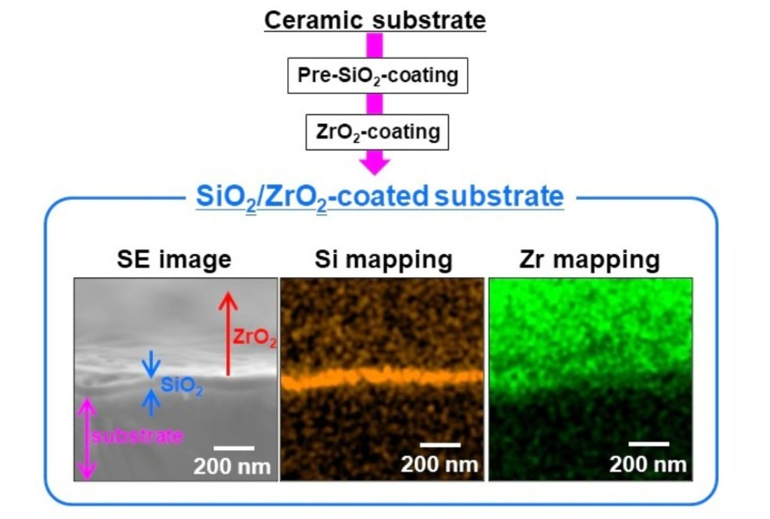
3.4. ZrO2-Coating on Pre-SiO2-Coated Substrate

Figure 5(a1) shows an SEM image of the surface of SiO2/ZrO2-coated substrate. The ZrO2-coating was performed once. Few ZrO2 particles were present on the coated substrate surface, which implied that, when the ZrO2-coating was performed, the deposition of ZrO2 particles preferentially occurred. Although the detailed mechanism of the preferential ZrO2-coating is still unclear, the superiority of the pre-SiO2-coating was demonstrated. Figure 5(a2) shows an SEM image of the cross-section of SiO2/ZrO2-coated substrate, from which the existence of a ZrO2 film can be confirmed. No film could be identified without pre-SiO2-coating, as shown in Figure 4(a2). Accordingly, the pre-SiO2-coating was found to facilitate ZrO2-coating.
Figure 5(b1) shows an SEM image of surface of SiO2/ZrO2-coated substrate. The ZrO2- coating was carried out three times. The image was similar to that with one round of ZrO2-coating; few ZrO2 particles were present on the coated substrate surface. Figure 5(b2) shows an SEM image of cross-section of SiO2/ZrO2-coated substrate. The ZrO2 film with a thickness of ca. 100 nm was clearly observed, and the film was firmly formed on the substrate without peeling off, even under the formation of such a thick ZrO2 film.
Figure 6a shows an SE image of the cross-section of SiO2/ZrO2-coated substrate, in which ZrO2-coating was performed three times. The cross-section and the surface of the SiO2/ZrO2-coated substrate can be observed in the lower and upper halves, respectively. The image also appears to move out of focus toward the top of the image. Figure 6b shows an elemental map of Si in the cross-section of the SiO2/ZrO2-coated substrate. The Si was detected almost in a straight line, was not detected on the substrate, and was absolutely derived from the pre-coated SiO2. This observation implied that the ZrO2 film had formed on the pre-SiO2-coated substrate, such that the SiO2 film surface was concealed by the ZrO2 film, resulting in no Si being detected on the substrate. Figure 6c shows an elemental map of Zr in a cross-section of SiO2/ZrO2-coated substrate. The Zr can be seen to be distributed only on the substrate. This indicated that the substrate was coated with the ZrO2 film, which supported the implication of a successful ZrO2-coating on the pre-SiO2-coated substrate.
The SiO2/ZrO2-coated substrate shown in Figure 5(b1) was further characterized by XPS, as follows. Figure 7 shows the atomic ratios in the SiO2/ZrO2-coated substrate, which were estimated using the XPS peak area intensities, as a function of the number of Ar+ etching steps. For an etching number of 0, the atomic ratios of Si, oxygen (O), and Zr were 29.5, 49.0, and 21.5 atom%, respectively. The atomic ratio of Zr decreased to 9.1 atom% at an etching number of 1. In contrast, the Si and O ratios increased to 34.9 and 56.0 atom% with one round of etching. After the first etching, the atomic ratios of Si, O, and Zr remained almost constant. This result indicated the presence of ZrO2 on the substrate surface, while removal of the ZrO2 film through etching exposed the surfaces of the SiO2 on the substrate. Accordingly, both the EDS mapping shown in Figure 6b,c and the XPS measurements shown in Figure 7 support the successful pre-SiO2 coating and ZrO2-coating on the pre-SiO2-coated substrate. Over an etching number of one, the atomic ratios of Si, O, and Zr remained almost constant, indicating that the first etching removed most of the ZrO2 film on the pre-SiO2-coated substrate.
Figure 8 shows XPS spectra in the O 1s binding energy region of the SiO2/ZrO2-coated substrate. The XPS spectra were curve-fitted by superposing several Gaussian peaks, in which the peak position, peak intensity, and full width at half maximum (FWHM) value were considered as parameters in the fitting process. The curve fitting provided four spectra with binding energies of 529.7, 531.2, 531.9, and 533.8 eV; according to [33,34], these were attributed to the O atoms of Zr–O, Si–O–Zr, Si–O, and Si-OH, respectively. Various bonds between O and other metals were confirmed. The atomic ratios of bonds estimated from the XPS peak area intensities are shown in Figure 9. The ratio of Zr–O bonds decreased with the first etching, then remained almost constant with a higher etching number. In contrast, the ratio of Si–O bonds increased with increasing etching number. These results indicated that etching initially removed the ZrO2 layers, composed mainly of Zr–O bonds, and exposed the pre-coated SiO2 layers. These results also supported the successful pre-SiO2-coating and ZrO2-coating on the pre-SiO2-coated substrate. The Si–O–Zr result revealed that the alkoxyl groups of TEOS that were unhydrolyzed and present on the film surface reacted with Zr butoxide to form Si–O–Zr bonds. Thus, pre-SiO2-coating was considered to promote the formation of Si-O-Zr bonds and, consequently, the following ZrO2-coating. The ratio of Si–O–Zr bonds increased with the first etching, then decreased with higher etching number. This indicated that the first etching removed the ZrO2 layers and exposed boundary layers with many Si–O–Zr bonds, while further etching removed the boundary layers, exposing the pre-coated SiO2 layers. This indication was in good agreement with the indications based on the Si–O and Zr–O bonds.

4. Conclusions

ZrO2-coating was successfully performed by initiating a sol–gel reaction in the presence of the substrate. The ZrO2 films were not broken, even after the annealing at 600 °C in air. Several ZrO2 particles were also deposited on the substrate. For the pre-SiO2-coated substrate, the amount of such ZrO2 particles was reduced and thick ZrO2 films were obtained. Pre-SiO2 coating increased the affinity between the ZrO2 layer and the substrate surface through the formation of Si–O–Zr bonds produced by the reaction of the ZTB and the alkoxyl groups of incompletely hydrolyzed TEOS on the substrate. Further studies focused on optimization of the fabrication conditions and the details of the ZrO2-coating mechanism are required for the effective practical use of the described ZrO2-coating method.

Author Contributions

A.M. conducted the experiments and wrote the manuscript; T.Y. analyzed the data; N.Y. and K.N. edited the manuscript; Y.K. conceived and designed the research and edited the manuscript. All authors have read and agreed to the published version of the manuscript.

Funding

This research was partially supported by Mitsubishi Materials Corporation.

Data Availability Statement

All data were included in the manuscript.

Conflicts of Interest

The authors declare no conflict of interest.

References

  1. Chen, S.; Liu, J. Pervasive liquid metal printed electronics: From concept incubation to industry. Iscience 2021, 24, 102026. [Google Scholar] [CrossRef] [PubMed]
  2. Marquardt, O. Simulating the electronic properties of semiconductor nanostructures using multiband k⋅p models. Comput. Mater. Sci. 2021, 194, 110318. [Google Scholar] [CrossRef]
  3. Li, K.; Zhang, S.; Tan, Q.; Wu, X.; Li, Y.; Li, Q.; Fan, J.; Lv, K. Insulator in photocatalysis: Essential roles and activation strategies. Chem. Eng. J. 2021, 426, 130772. [Google Scholar] [CrossRef]
  4. Yang, B.; He, M.; Wen, K.; Xiong, D.; Feng, Y.; Ta, S.; Yang, Z. Comparison of morphology, electrical properties and sensitivity between bulk and thin-film Mn1.5Co1Ni0.5O4 thermistors. Ceram. Int. 2020, 46, 27134–27142. [Google Scholar] [CrossRef]
  5. Wang, B.; Wang, J.; Yao, J.; Chang, A. Bismuth and zinc co-modified Mn1⋅1Co1⋅5Fe0⋅4O4 negative temperature coefficient sensitive ceramics: Structural and electrical characterization. Mater. Chem. Phys. 2021, 257, 123604. [Google Scholar] [CrossRef]
  6. Jeon, J.E.; Park, K.R.; Kim, K.M.; Ahn, C.; Lee, J.; Yu, D.Y.; Bang, J.; Oh, N.; Han, H.; Mhin, S. Effect of Cu/Fe addition on the microstructures and electrical performances of Ni-Co-Mn oxides. J. Alloys Compd. 2021, 859, 157769. [Google Scholar] [CrossRef]
  7. Wei, Y.; Zhang, B.; Fu, Z.; Liu, Y.; Chen, H.; Ni, L.; Zhou, Y.; Chang, A. Synthesis and high thermal stability of Mn doped Y2/3Cu3Ti4O12 negative temperature coefficient ceramic. J. Solid State Chem. 2021, 303, 122536. [Google Scholar] [CrossRef]
  8. Gao, C.; Li, Z.; Yang, L.; Peng, D.; Zhang, H. Investigation of electrical and aging properties of Bi-modified (Zn0.4Ni0.6)1-xNaxO ceramic thermistors. J. Eur. Ceram. Soc. 2021, 41, 4160–4166. [Google Scholar] [CrossRef]
  9. Chi, F.; Zeng, Y.; Liu, C.; Liang, D.; Li, Y.; Xie, R.; Pan, N.; Ding, C. Enhancing mechanical stability of sol-gel silica antireflection coatings via ammonia treatment at low temperature. Results Phys. 2020, 18, 103315. [Google Scholar] [CrossRef]
  10. Pan, Z.; Guo, J.; Li, S.; Li, X.; Zhang, H. Properties of alumina coatings prepared on silica-based ceramic substrate by plasma spraying and sol-gel dipping methods. Ceram. Int. 2021, 47, 27453–27461. [Google Scholar] [CrossRef]
  11. Yousaf, H.; Azhar, M.; Bashir, M.; Riaz, S.; Kayani, Z.N.; Naseem, S. Effect of capping agent on microwave assisted sol-gel synthesized zirconia coatings for optical applications. Optik 2020, 222, 165297. [Google Scholar] [CrossRef]
  12. Yu, J.; Ji, G.; Liu, Q.; Zhang, J.; Shi, Z. Effect of sol-gel ZrO2 films on corrosion behavior of the 304 stainless steel in coal-gases environment at high temperature. Surf. Coat. Technol. 2017, 331, 21–26. [Google Scholar] [CrossRef]
  13. Raza, M.; Boulet, P.; Pierson, J.F.; Snyders, R.; Konstantinidis, S. Thermal stability of oxygen vacancy stabilized zirconia (OVSZ) thin films. Surf. Coat. Technol. 2021, 409, 126880. [Google Scholar] [CrossRef]
  14. Xiang, D.; Xu, Y.; Bai, W.; Lin, H. Dental zirconia fabricated by stereolithography: Accuracy, translucency and mechanical properties in different build orientations. Ceram. Int. 2021, 47, 28837–28847. [Google Scholar] [CrossRef]
  15. Zadeh, P.N.; Lümkemann, N.; Sener, B.; Eichberger, M.; Stawarczyk, B. Flexural strength, fracture toughness, and translucency of cubic/tetragonal zirconia materials. J. Prosthet. Dent. 2018, 120, 948–954. [Google Scholar] [CrossRef] [Green Version]
  16. Zhang, W.; Ji, G.; Bu, A.; Zhang, B. Corrosion and tribological behavior of ZrO2 films prepared on stainless steel surface by the sol-gel method. ACS Appl. Mater. Interfaces 2015, 7, 28264–28272. [Google Scholar] [CrossRef]
  17. Varanasi, V.G.; Besmann, T.M.; Payzant, E.A.; Starr, T.L.; Anderson, T.J. Thermodynamic analysis and growth of ZrO2 by chloride chemical vapor deposition. Thin Solid Films 2008, 516, 6133–6139. [Google Scholar] [CrossRef]
  18. Arunkumar, P.; Aarthi, U.; Sribalaji, M.; Mukherjee, B.; Keshri, A.K.; Tanveer, W.H.; Cha, S.W.; Babu, K.S. Deposition rate dependent phase/mechanical property evolution in zirconia and ceria-zirconia thin film by EB-PVD technique. J. Alloys Compd. 2018, 765, 418–427. [Google Scholar] [CrossRef]
  19. Garg, N.; Bera, S.; Velmurugan, S. Effect of coating thickness and grain size on the electrochemical properties of hydrothermally deposited nano-ZrO2 coatings on stainless steel surface. Thin Solid Films 2019, 670, 60–67. [Google Scholar] [CrossRef]
  20. Pareja, R.R.; Ibáñez, R.L.; Martín, F.; Ramos-Barrado, J.R.; Leinen, D. Corrosion behaviour of zirconia barrier coatings on galvanized steel. Surf. Coat. Technol. 2006, 200, 6606–6610. [Google Scholar] [CrossRef]
  21. Asiltürk, M.; Burunkaya, E.; Sayılkan, F.; Kiraz, N.; Arpaç, E. Structural and optical properties of thin films prepared from surface modified ZrO2. J. Non-Cryst. Solids 2011, 357, 206–210. [Google Scholar] [CrossRef]
  22. Soo, M.T.; Prastomo, N.; Matsuda, A.; Kawamura, G.; Muto, H.; Noor, A.F.M.; Lockman, Z.; Cheong, K.Y. Elaboration and characterization of sol-gel derived ZrO2 thin films treated with hot water. Appl. Surf. Sci. 2012, 258, 5250–5258. [Google Scholar] [CrossRef]
  23. Nouri, E.; Shahmiri, M.; Rezaie, H.R.; Talayian, F. A comparative study of heat treatment temperature influence on the thickness of zirconia sol-gel thin films by three different techniques: SWE, SEM and AFM. Surf. Coat. Technol. 2012, 206, 3809–3815. [Google Scholar] [CrossRef]
  24. Boratto, M.H.; Congiu, M.; dos Santos, S.B.O.; Scalvi, L.V.A. Annealing temperature influence on sol-gel processed zirconium oxide thin films for electronic applications. Ceram. Int. 2018, 44, 10790–10796. [Google Scholar] [CrossRef] [Green Version]
  25. Hao, D.; Song, Y.X.; Zhang, Y.; Fan, H.T. Nanocomposites of reduced graphene oxide with pure monoclinic-ZrO2 and pure tetragonal-ZrO2 for selective adsorptive removal of oxytetracycline. Appl. Surf. Sci. 2021, 543, 148810. [Google Scholar] [CrossRef]
  26. Fu, L.; Li, B.; Xu, G.; Huang, J.; Engqvist, H.; Xia, W. Size-driven phase transformation and microstructure evolution of ZrO2 nanocrystallites associated with thermal treatments. J. Eur. Ceram. Soc. 2021, 41, 5624–5633. [Google Scholar] [CrossRef]
  27. Moriya, Y.; Navrotsky, A. High-temperature calorimetry of zirconia: Heat capacity and thermodynamics of the monoclinic–tetragonal phase transition. J. Chem. Thermodyn. 2006, 38, 211–223. [Google Scholar] [CrossRef]
  28. Lega, D.; Antonini, A.; Ciccioli, A.; Brutti, S.; Lenzuni, P. Low scan rate DSC study of the monoclinic-tetragonal transition in zirconia. Thermochim. Acta 2011, 524, 18–22. [Google Scholar] [CrossRef]
  29. Zhao, S.; Ma, J.; Lin, X.; Cheng, X.; Zhao, X.; Hao, S.; Li, Z.; Deng, C.; Liu, B. Preparation of tetragonal zirconia microspheres as surrogate precursor for uranium nitride microspheres. Nucl. Eng. Des. 2020, 362, 110542. [Google Scholar] [CrossRef]
  30. Bouvier, P.; Godlewski, J.; Lucazeau, G. A Raman study of the nanocrystallite size effect on the pressure-temperature phase diagram of zirconia grown by zirconium-based alloys oxidation. J. Nucl. Mater. 2002, 300, 118–126. [Google Scholar] [CrossRef]
  31. Deng, B.; Luo, J.; Harris, J.T.; Smith, C.M. Critical stress map for ZrO2 tetragonal to monoclinic phase transformation in ZrO2-toughened glass-ceramics. Materialia 2020, 9, 100548. [Google Scholar] [CrossRef]
  32. Gao, Y.; Masuda, Y.; Ohta, H.; Koumoto, K. Room-temperature preparation of ZrO2 precursor thin film in an aqueous peroxozirconium-complex solution. Chem. Mater. 2004, 16, 2615–2622. [Google Scholar] [CrossRef]
  33. Kim, J.M.; Chang, S.M.; Kim, S.; Kim, K.S.; Kim, J.; Kim, W.S. Design of SiO2/ZrO2 core-shell particles using the sol-gel process. Ceram. Int. 2009, 35, 1243–1247. [Google Scholar] [CrossRef]
  34. Saha, S.; Hamid, S.B.A. CuZrO3 nanoparticles catalyst in aerobic oxidation of vanillyl alcohol. RSC Adv. 2017, 7, 9914–9925. [Google Scholar] [CrossRef]
Figure 1. Information on the substrate used in the present work: (a) Photograph of the substrate; (b): SEM image of the substrate surface obtained by dicing; (c) SEM image of the substrate surface obtained by slicing; and (d) XRD pattern of the substrate (●: Fe3O4).
Processes 10 02217 g001
Figure 2. XRD patterns of sol–gel products (a) as-prepared and annealed at (b) 100, (c) 200, (d) 300, (e) 400, (f) 500, and (g) 600 °C. ●: t-ZrO2, 〇: m-ZrO2.
Processes 10 02217 g002
Figure 3. SE image and corresponding EDX elemental analysis of SiO2-coated substrate: (a) SE image and (b) elemental map of Si (orange) of cross-section of substrate after one SiO2-coating, respectively.
Processes 10 02217 g003
Figure 4. SEM images, SE images, and corresponding EDX elemental analysis of ZrO2-coated substrates. Images (a1) and (a2) show SEM images of the surface and cross-section of ZrO2-coated substrates after one round of ZrO2-coating, respectively. Images (b1) and (b2) show SEM images of the surface and cross section of ZrO2-coated substrates after three rounds of ZrO2-coating, respectively. Images (c1) and (c2) show an SE image and an elemental map of Zr (purple) of the cross-section of the substrate after rounds of ZrO2-coating, respectively.
Processes 10 02217 g004
Figure 5. SEM images of SiO2/ZrO2-coated substrates. Images (a1) and (a2) show SEM images of the surface and cross-section of SiO2/ZrO2-coated substrate after one round of ZrO2-coating, respectively. Images (b1) and (b2) show SEM images of the surface and cross-section of SiO2/ZrO2-coated substrate after three rounds of ZrO2-coating, respectively. The pre-SiO2-coating for the raw substrate was performed three times prior to ZrO2-coating.
Processes 10 02217 g005
Figure 6. SE image and corresponding EDX elemental analysis of SiO2/ZrO2-coated substrates. Both SiO2- and ZrO2-coating processes were carried out three times. (a) SE image; and (b) and (c) elemental maps of Si (orange) and Zr (green), respectively. The sample was the same as that in Figure 5(b2).
Processes 10 02217 g006
Figure 7. Atomic ratios in SiO2/ZrO2-coated substrate as a function of the number of Ar+ etching steps. The as-prepared sample was the same as that in Figure 5(b1).
Processes 10 02217 g007
Figure 8. O 1s XPS spectra of surfaces of SiO2/ZrO2-coated substrates. The black curves are the measured spectra. The numbers of etches are 0, 1, 2, and 3 for spectra (ad), respectively. Each measured spectrum is fitted with Gaussian peaks, giving binding energies of 529.7 eV (blue curve), 531.2 eV (purple curve), 531.9 eV (red curve), and 533.8 eV (green curve), attributed to the O atoms of Zr–O, Si–O–Zr, Si–O, and Si–OH, respectively. The as-prepared sample was the same as that in Figure 5(b1).
Processes 10 02217 g008
Figure 9. Atomic ratios of bonds on surfaces of SiO2/ZrO2-coated substrates as a function of the number of Ar+ etching steps. (●) Zr-O, (△) Si-O-Zr, (〇) Si-O, and (▲) Si-OH. The as-prepared sample was the same as that in Figure 5(b1).
Processes 10 02217 g009
Publisher’s Note: MDPI stays neutral with regard to jurisdictional claims in published maps and institutional affiliations.

