
Custom-Shaped Carbon Xerogel Materials by 3D Printing


Abstract
1. Introduction
2. Materials and Methods
2.1. Preparation of Carbon precursor Solution
2.2. Preparation of Custom-Shaped Carbon Monoliths Using a 3D-Printed Mold
2.3. Selection of Plastic as the Mold’s Raw Material
- Has to withstand a temperature of 85 °C for 72 h;
- Must be chemically inert towards the reagents in the XC synthesis (namely water, formaldehyde, Na2CO3, and resorcinol);
- Must be able to be dissolved or removed via a liquid (other than formaldehyde and water).
- If more than one type of material can fit all the previous criteria, then cost (of the plastic and the corresponding solvent), printability of the plastic, mechanical properties of the plastic, and ecological/health impact of the solvent will be used to make a choice.
2.4. Design of the Mold and Determination of Ideal Parameters of the 3D Printer
- The space to be filled by the sol (i.e., the negative of the mold) must have a geometry where diffusion from the outside was as fast as possible. This is intended to speed up the diffusion of adsorbents into the finished material during the final application.
- The parts had to be printable consistently, with the design of the mold limiting the possible defects.
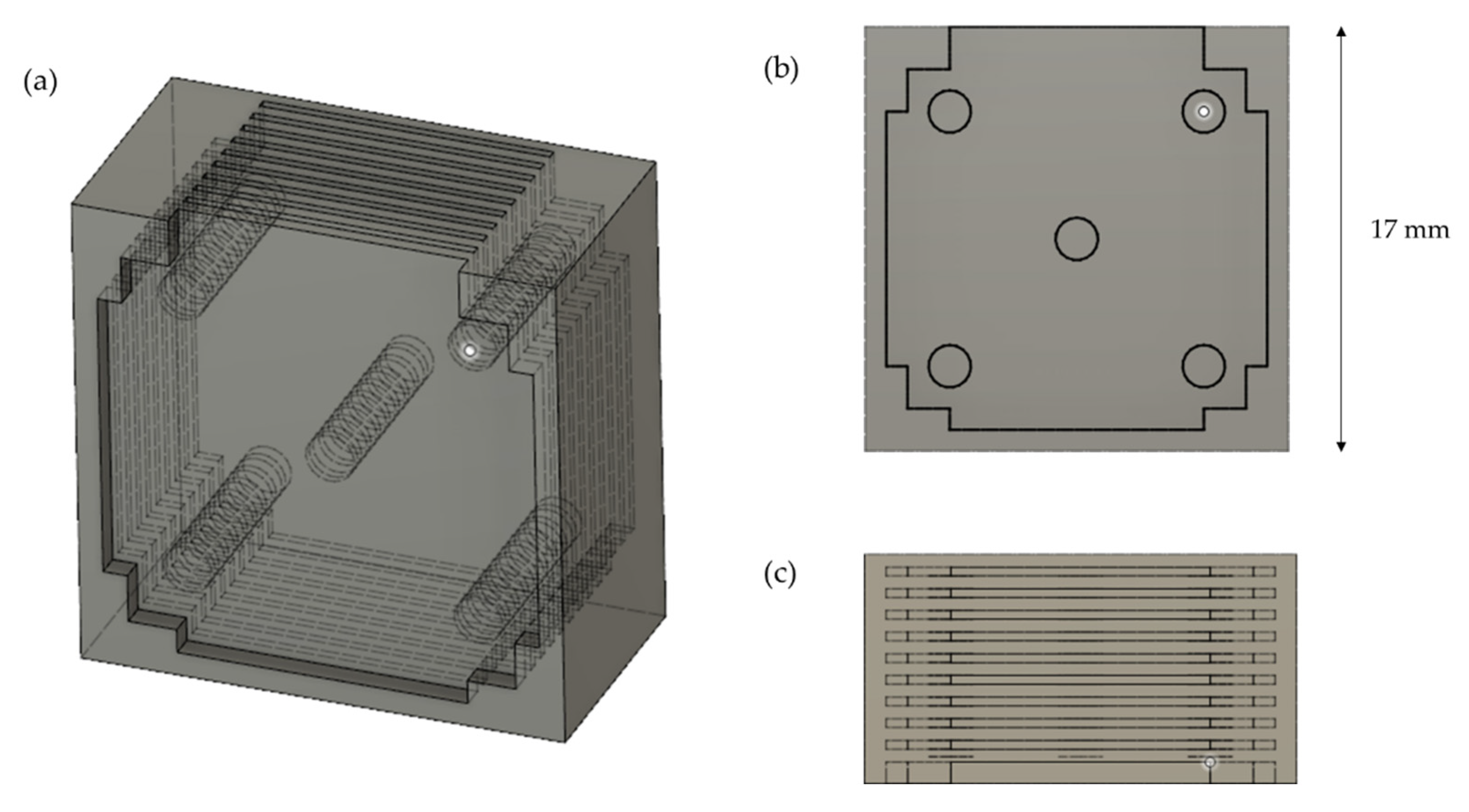
- The design of the plastic mold must not induce mechanical weaknesses.
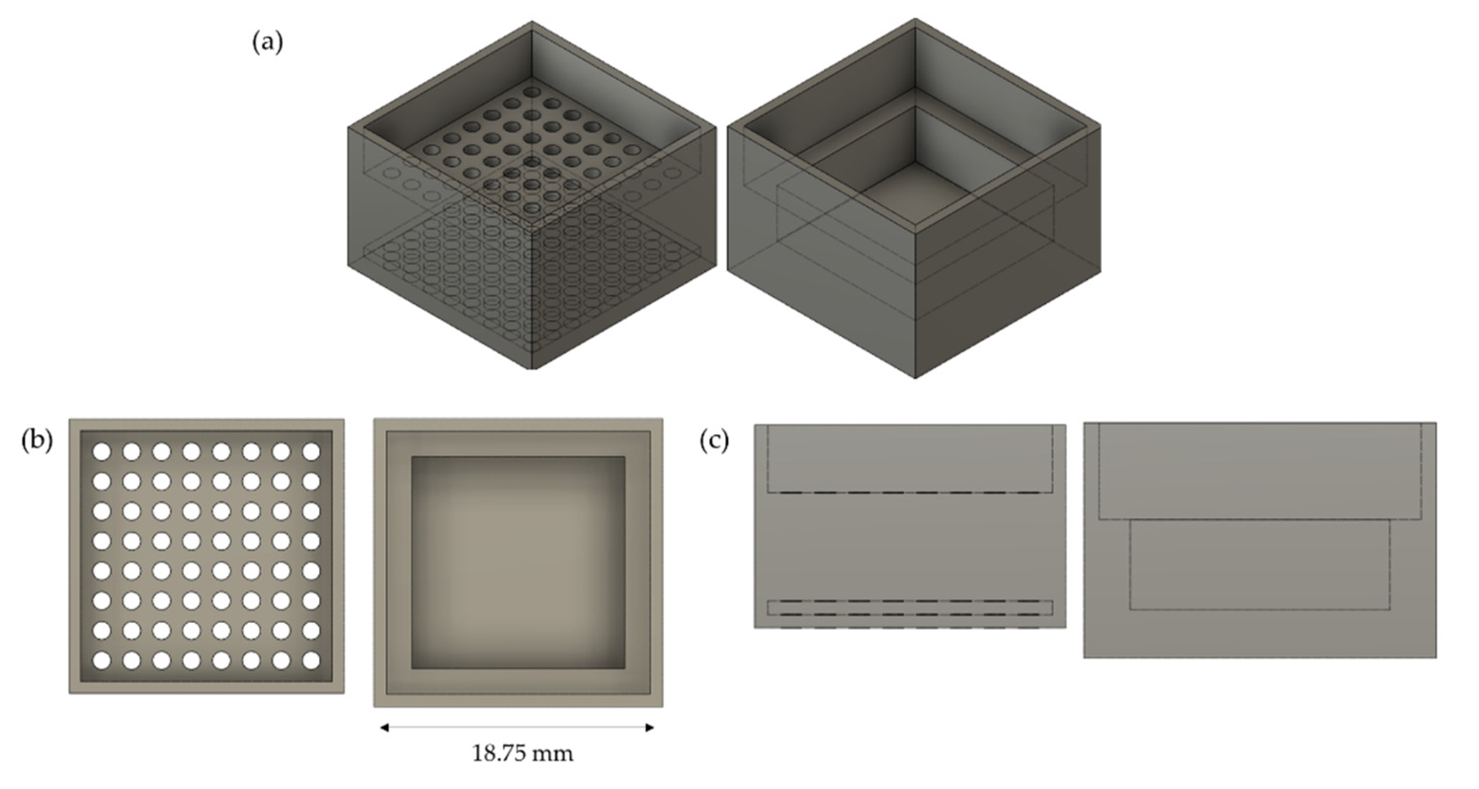
- The combination of parts had to constitute an airtight set, from where the sol’s evaporation should be limited as much as possible.
- The mold had to be easily wettable, i.e., the sol should be easily poured (or forced) into the mold.
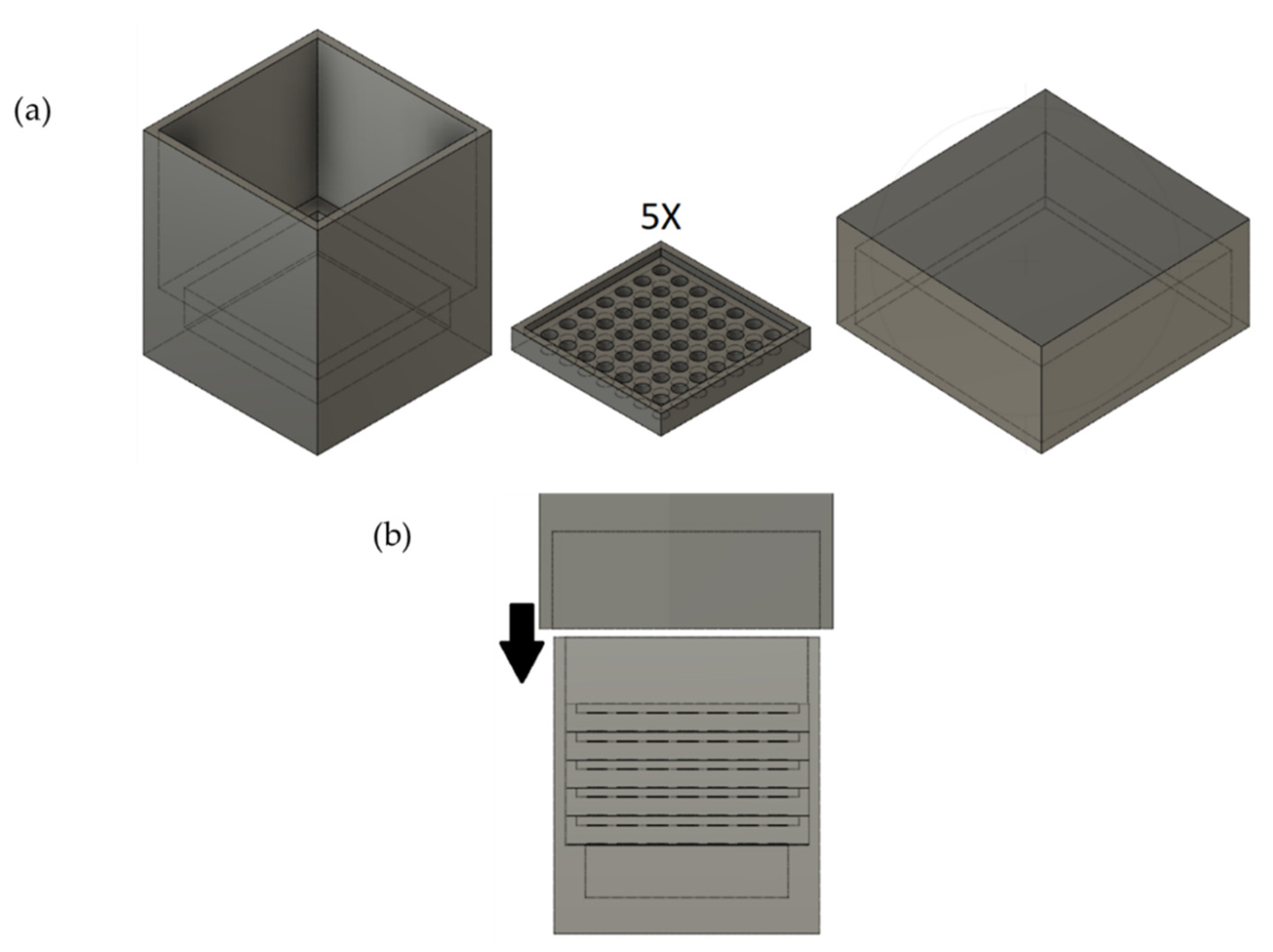
2.5. Method of Removal of the Mold
- (i)
- Pyrolyze the mold (using the method described previously).
- (ii)
- Dissolve the mold by putting it in 600 mL of the selected solvent, dispose of it after one day, and replace it with new solvent until the plastic is fully dissolved. When not much plastic is left, the process is aided by sonication. During the dissolution, there can be either:
- (a)
- No stirring;
- (b)
- Mild stirring;
- (c)
- Strong stirring;
- (d)
- Or mild stirring with the sample captured in a metallic net.
- (iii)
- A combination of dissolution and pyrolysis, as explained by the following modus operandi. Dissolve the mold by putting it in 600 mL of the selected solvent, dispose of it after one day, and replace it with new solvent until the plastic is mostly dissolved, i.e., when the outermost surface of the carbon xerogel is completely visible and when the solvent is not opaque after 24 h in contact with the carbon–plastic assembly. Afterward, the material and the leftover plastic are pyrolyzed in the same manner as previously described. The sonication and agitation conditions are the same as in the previous step.
3. Results
3.1. Selection of Plastic as the Mold’s Raw Material
3.1.1. First Criterion: Glass Transition Temperature
3.1.2. Second Criterion: Chemical Resistance
3.1.3. Third Criterion: Ability to Be Dissolved
3.1.4. Comparison of Remaining Candidates
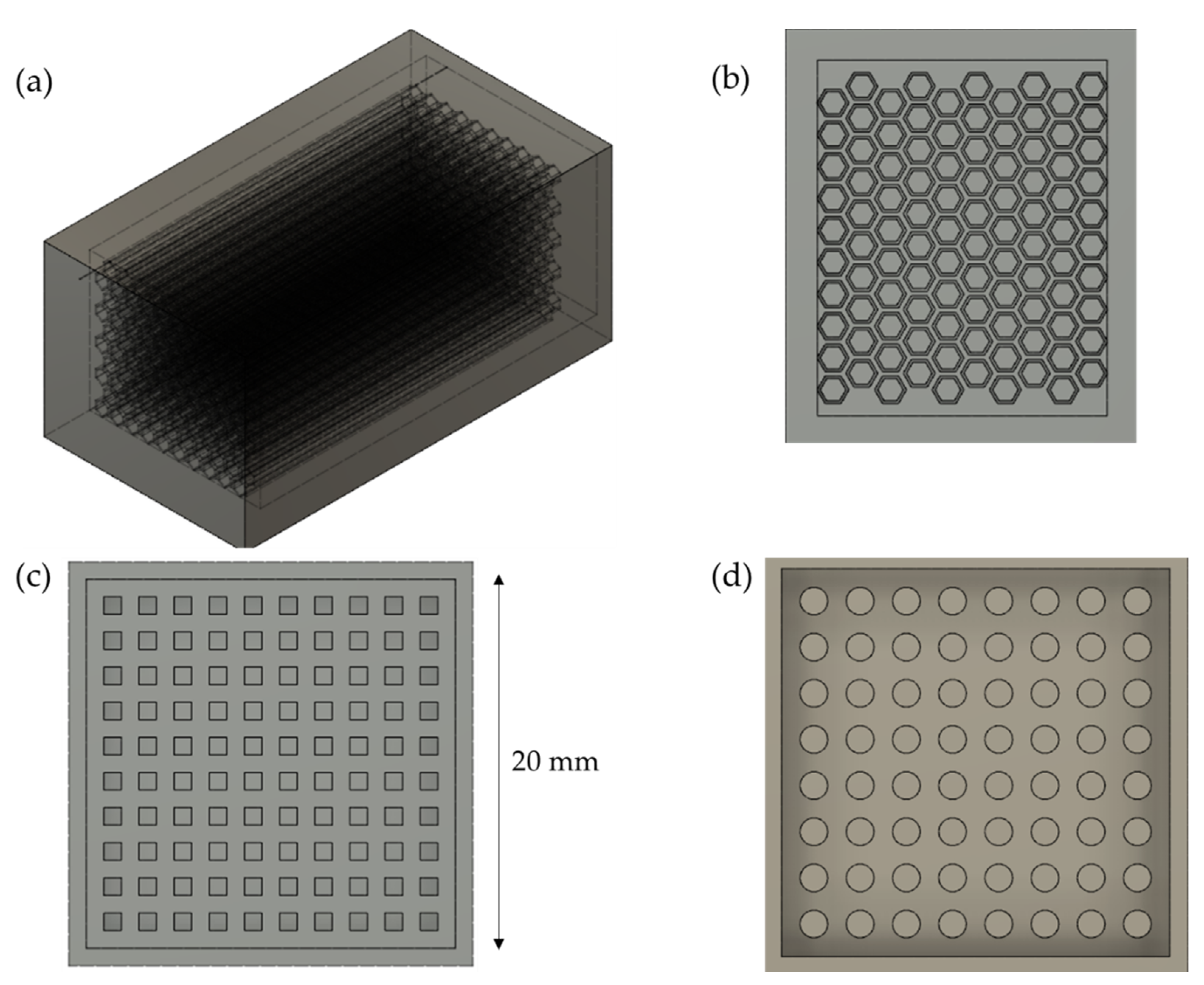
3.2. Design of the Mold
3.3. Determination of Ideal Parameters of the 3D Printer
- Layer height (h): The height of each layer but the first. Thicker layers are printed quicker but result in coarser, less accurate renditions of the design.
- First layer height (h0): the first layer is sometimes thicker than the other layers to increase adhesion to the bed while printing.
- Fill density (Fd): Only a fraction of the infill is printed in order to save material and time. The fill density, expressed in %, is the value of this fraction.
- Presence of a brim: a brim is a detachable part printed next to the object’s first layer to increase its adhesion to the bed.
- Extrusion multiplier (E): this empirical parameter multiplies the default flow of plastic by a certain value, helping with the quality of the final print.
- Extruder temperature (TE) and extruder temperature for the first layer (TE0): One of the most important parameters, dependent on the printer, the plastic, the setup, and the environment. A suboptimal extruder temperature can lead to various problems, such as defects in the material and clogging of the extruder.
- Bed temperature (TB) and bed temperature for the first layer (TB0): Also an important parameter, especially for poorly adhering ABS. It must be carefully chosen to control shrinking and warping phenomena.
- Nozzle diameter: Using a smaller nozzle leads to slower but more precise prints.
3.4. Method of Removal of the Mold
- (i)
- Pyrolyzing the mold leads to a high quantity of exhaust gas so that the pyrolysis oven must be carefully cleaned after the operation.
- (ii)
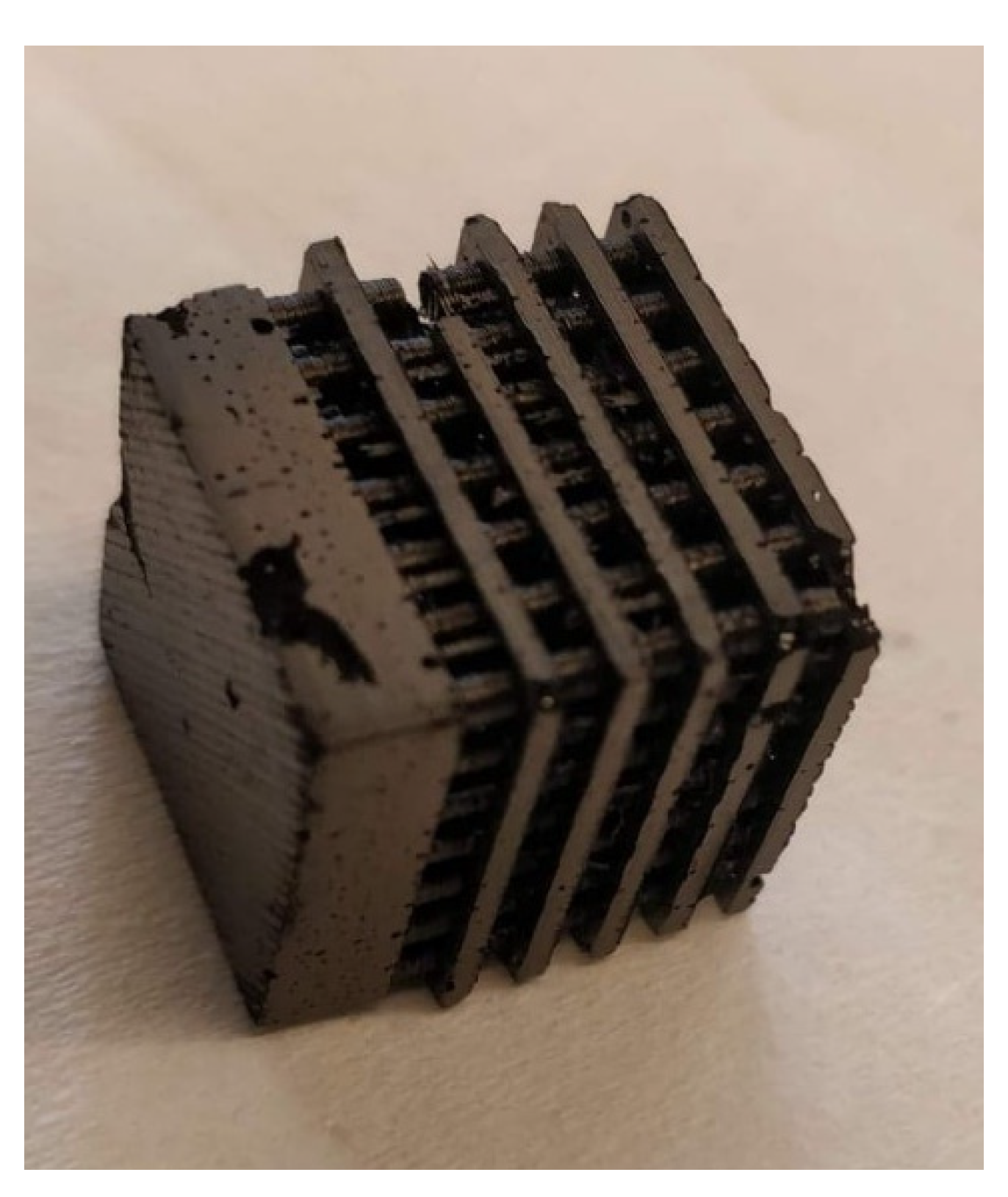
- When the mold is dissolved by immersing it repeatedly in the solvent, stirring plays a key role. Indeed, the weaker the agitation, the less efficient the dissolution of the plastic. However, another phenomenon must be taken into account: dissolved ABS strongly settles at the bottom, forming a thick, sticky paste. When using no agitation, disposing of the ABS–acetone mix is particularly hard, as the half-dissolved mold sticks to the bottom of the container, surrounded by sticky paste. Stronger agitations partially solve this problem, but sometimes cause the carbon–mold assembly to break or to move. Thus, a good compromise is to use mild agitation (around 20 RPM). This was found satisfactory to keep the assembly from sticking to the bottom of the container, while not destroying or altering it. An even better solution is to use a metallic net: this way, the sample is held above the bottom of the container. This means that the sample is in contact with clearer solvent (as the dissolved plastic settles to the bottom). Furthermore, the assembly can be easily and safely pulled from the solution by using the net. After the ensuing pyrolysis step, the material did not exhibit major defects, although a few small holes were visible on the surface.
- (iii)
- Now that the agitation conditions are selected, one can wonder what quantity of solvent is needed to fully remove the mold in these conditions. After experimenting, no definitive quantity could be determined. Indeed, even after 10 cycles of dissolving the plastic, it was still found in small quantities on the carbon material when carefully examined. Perfect removal of the plastic is thus probably too optimistic.
4. Conclusions
Author Contributions
Funding
Data Availability Statement
Acknowledgments
Conflicts of Interest
References
- Páez, C.A.; Contreras, M.S.; Léonard, A.; Blacher, S.; Olivera-Fuentes, C.G.; Pirard, J.P.; Job, N. Effect of CO2 Activation of Carbon Xerogels on the Adsorption of Methylene Blue. Adsorption 2012, 18, 199–211. [Google Scholar] [CrossRef]
- Karaca, S.; Gürses, A.; Açikyildiz, M.; Ejder (Korucu), M. Adsorption of Cationic Dye from Aqueous Solutions by Activated Carbon. Microporous Mesoporous Mater. 2008, 115, 376–382. [Google Scholar] [CrossRef]
- Yu, J.X.; Li, B.H.; Sun, X.M.; Yuan, J.; Chi, R.-A. Polymer Modified Biomass of Baker’s Yeast for Enhancement Adsorption of Methylene Blue, Rhodamine B and Basic Magenta. J. Hazard. Mater. 2009, 168, 1147–1154. [Google Scholar] [CrossRef] [PubMed]
- Ip, A.W.M.; Barford, J.P.; McKay, G. A Comparative Study on the Kinetics and Mechanisms of Removal of Reactive Black 5 by Adsorption onto Activated Carbons and Bone Char. Chem. Eng. J. 2010, 157, 434–442. [Google Scholar] [CrossRef]
- Job, N.; Pirard, R.; Marien, J.; Pirard, J.P. Porous Carbon Xerogels with Texture Tailored by PH Control during Sol-Gel Process. Carbon 2004, 42, 619–628. [Google Scholar] [CrossRef]
- Job, N.; Théry, A.; Pirard, R.; Marien, J.; Kocon, L.; Rouzaud, J.N.; Béguin, F.; Pirard, J.P. Carbon Aerogels, Cryogels and Xerogels: Influence of the Drying Method on the Textural Properties of Porous Carbon Materials. Carbon 2005, 43, 2481–2494. [Google Scholar] [CrossRef]
- Job, N.; Maillard, F.; Chatenet, M.; Gommes, C.J.; Lambert, S.; Hermans, S.; Regalbuto, J.R.; Pirard, J.-P. Synthesis and Characterization of Highly Loaded Pt/Carbon Xerogel Catalysts Prepared by the Strong Electrostatic Adsorption Method. Stud. Surf. Sci. Catal. 2010, 175, 169–176. [Google Scholar]
- Redwood, B.; Schöffer, F.; Garret, B. The 3D Printing Handbook: Technologies, Design and Applications; 3D Hubs B.V.: Amsterdam, The Netherlands, 2017. [Google Scholar]
- Li, H.; Zhang, Y.; Tai, Y.; Zhu, X.; Qi, X.; Zhou, L.; Li, Z.; Lan, H. Flexible Transparent Electromagnetic Interference Shielding Films with Silver Mesh Fabricated Using Electric-Field-Driven Microscale 3D Printing. Opt. Laser Technol. 2022, 148, 107717. [Google Scholar] [CrossRef]
- Li, H.; Li, Z.; Li, N.; Zhu, X.; Zhang, Y.F.; Sun, L.; Wang, R.; Zhang, J.; Yang, Z.; Yi, H.; et al. 3D Printed High Performance Silver Mesh for Transparent Glass Heaters through Liquid Sacrificial Substrate Electric-Field-Driven Jet. Small 2022, 18, 2107811. [Google Scholar] [CrossRef]
- Khan, S.B.; Irfan, S.; Lam, S.S.; Sun, X.; Chen, S. 3D Printed Nanofiltration Membrane Technology for Waste Water Distillation. J. Water Process Eng. 2022, 49, 102958. [Google Scholar] [CrossRef]
- Li, Z.; Li, H.; Zhu, X.; Peng, Z.; Zhang, G.; Yang, J.; Wang, F.; Zhang, Y.F.; Sun, L.; Wang, R.; et al. Directly Printed Embedded Metal Mesh for Flexible Transparent Electrode via Liquid Substrate Electric-Field-Driven Jet. Adv. Sci. 2022, 9, 2105331. [Google Scholar] [CrossRef] [PubMed]
- Piedboeuf, M.L.C.; Léonard, A.F.; Traina, K.; Job, N. Influence of the Textural Parameters of Resorcinol-Formaldehyde Dry Polymers and Carbon Xerogels on Particle Sizes upon Mechanical Milling. Colloids Surf. A Physicochem. Eng. Asp. 2015, 471, 124–132. [Google Scholar] [CrossRef]
- Piedboeuf, M.L.C.; Léonard, A.F.; Reichenauer, G.; Balzer, C.; Job, N. How Do the Micropores of Carbon Xerogels Influence Their Electrochemical Behavior as Anodes for Lithium-Ion Batteries? Microporous Mesoporous Mater. 2019, 275, 278–287. [Google Scholar] [CrossRef]
- Piedboeuf, M.L.C.; Job, N.; Aqil, A.; Busby, Y.; Fierro, V.; Celzard, A.; Detrembleur, C.; Léonard, A.F. Understanding the Influence of Surface Oxygen Groups on the Electrochemical Behavior of Porous Carbons as Anodes for Lithium-Ion Batteries. ACS Appl. Mater. Interfaces 2020, 12, 36054–36065. [Google Scholar] [CrossRef] [PubMed]
- Brostow, W.; Chiu, R.; Kalogeras, I.M.; Vassilikou-Dova, A. Prediction of Glass Transition Temperatures: Binary Blends and Copolymers. Mater. Lett. 2008, 62, 3152–3155. [Google Scholar] [CrossRef]
- Available online: https://www.simplify3d.com/support/materials-guide/nylon/ (accessed on 4 August 2022).
- Kamthai, S.; Magaraphan, R. Thermal and Mechanical Properties of Polylactic Acid (PLA) and Bagasse Carboxymethyl Cellulose (CMCB) Composite by Adding Isosorbide Diesters. AIP Conf. Proc. 2015, 1664, 060006. [Google Scholar]
- Available online: http://www.plasticmoulding.ca/polymers/polypropylene.htm (accessed on 4 August 2022).
- Available online: https://www.marlinwire.com/blog/7-need-to-know-polypropylene-material-properties (accessed on 4 August 2022).
- Romanova, N.; Shafigullin, L.; Gabdrakhmanov, A.; Buyatova, S. Thermal Properties of Products Based on ABS/PC. MATEC Web Conf. 2019, 298, 00016. [Google Scholar] [CrossRef]
- Mao, Z.; Zhang, J. Toughening Effect of CPE on ASA/SAN Binary Blends at Different Temperatures. J. Appl. Polym. Sci. 2016, 133, 20. [Google Scholar] [CrossRef]
- Dupaix, R.B.; Boyce, M.C. Finite Strain Behavior of Poly(Ethylene Terephthalate) (PET) and Poly(Ethylene Terephthalate)-Glycol (PETG). Polymer 2005, 46, 4827–4838. [Google Scholar] [CrossRef]
- Solarski, S.; Ferreira, M.; Devaux, E. Characterization of the Thermal Properties of PLA Fibers by Modulated Differential Scanning Calorimetry. Polymer 2005, 46, 11187–11192. [Google Scholar] [CrossRef]
- Hummel, S.R.; Hossain, K.; Hayes, G.T. Biaxial Stress Relaxation of High Impact Polystyrene (HIPS) Above the Glass Transition Temperature. Polym. Eng. Sci. 2001, 41, 566–574. [Google Scholar] [CrossRef]
- Yang, H.; Lai, M.; Liu, W.; Sun, C.; Liu, J. Morphology and Thermal and Mechanical Properties of PBT/HIPS and PBT/HIPS-G-GMA Blends. J. Appl. Polym. Sci. 2002, 85, 2600–2608. [Google Scholar] [CrossRef]
- Alcock, B.; Cabrera, N.O.; Barkoula, N.M.; Reynolds, C.T.; Govaert, L.E.; Peijs, T. The Effect of Temperature and Strain Rate on the Mechanical Properties of Highly Oriented Polypropylene Tapes and All-Polypropylene Composites. Compos. Sci. Technol. 2007, 67, 2061–2070. [Google Scholar] [CrossRef]
- Kelco Chemical Compatibility Chart Abs. Available online: https://www.kelco.com.au/wp-content/uploads/2009/02/abs-chemical-compatibility-guide.pdf (accessed on 5 August 2022).
- Heikkinen, I.T.S.; Kauppinen, C.; Liu, Z.; Asikainen, S.M.; Spoljaric, S.; Seppälä, J.V.; Savin, H.; Pearce, J.M. Chemical Compatibility of Fused Filament Fabrication-Based 3-D Printed Components with Solutions Commonly Used in Semiconductor Wet Processing. Addit. Manuf. 2018, 23, 99–107. [Google Scholar] [CrossRef]
- Available online: https://www.simplify3d.com/support/materials-guide/hips/ (accessed on 4 August 2022).
- Available online: https://www.osti.gov/servlets/purl/4970 (accessed on 4 August 2022).
- Chen, Y.; Li, J.; Lu, J.; Ding, M.; Chen, Y. Synthesis and Properties of Poly(Vinyl Alcohol) Hydrogels with High Strength and Toughness. Polym. Test. 2022, 108, 107516. [Google Scholar] [CrossRef]
- Available online: https://www.calpaclab.com/polypropylene-chemical-compatibility-chart/ (accessed on 4 August 2022).
- Available online: https://rigid.ink/blogs/news/acetone-vapor-smoothing (accessed on 4 August 2022).
- Boborodea, A.; O’Donohue, S. Characterization of Polypropylene in Dibutoxymethane by High-Temperature Gel Permeation Chromatography with Triple Detection. Int. J. Polym. Anal. Charact. 2015, 20, 724–732. [Google Scholar] [CrossRef]
- Cheruthazhekatt, S.; Robertson, D.D.; Brand, M.; van Reenen, A.; Pasch, H. Solution Crystallization and Dissolution of Polyolefins as Monitored by a Unique Analytical Tool: Solution Crystallization Analysis by Laser Light Scattering. Anal. Chem. 2013, 85, 7019–7023. [Google Scholar] [CrossRef]
- Available online: https://www.simplify3d.com/support/materials-guide/abs/ (accessed on 4 August 2022).
- Available online: http://xahax.com/subory/Spec_ABS.pdf (accessed on 4 August 2022).
- Available online: https://dielectricmfg.com/knowledge-base/abs/ (accessed on 4 August 2022).
- Available online: https://www.simplify3d.com/support/materials-guide/asa/ (accessed on 4 August 2022).
- Available online: https://omnexus.specialchem.com/polymer-properties/properties/coefficient-of-linear-thermal-expansion (accessed on 4 August 2022).
- Available online: https://designerdata.nl/materials/plastics/thermo-plastics/acrylonitrile---styrene---acrylester (accessed on 4 August 2022).
- Available online: https://dielectricmfg.com/knowledge-base/petg/ (accessed on 4 August 2022).
- Available online: https://polymerdatabase.com/Commercial%20Polymers/PS2.html (accessed on 4 August 2022).
- Available online: https://www.simplify3d.com/support/materials-guide/polypropylene/ (accessed on 4 August 2022).
- Available online: https://www.engineeringtoolbox.com/linear-expansion-coefficients-d_95.html (accessed on 4 August 2022).
- Available online: https://designerdata.nl/materials/plastics/thermo-plastics/polypropylene-(cop.) (accessed on 4 August 2022).


| Polymer | Tg (°C) | Source |
|---|---|---|
| ABS | 105 | [21] |
| ASA | 113 | [22] |
| PETG | 80 | [23] |
| PLA | <67 | [24] |
| HIPS | 97 | [25,26] |
| PVA | 80 | [16] |
| PP | - a | [27] |
| Polymer | Resistance to Water | Resistance to Formaldehyde | Source |
|---|---|---|---|
| ABS | Excellent | Excellent | [28] |
| ASA | Excellent | Unknown | [29] |
| PETG | Excellent | Excellent | [23] |
| HIPS | Excellent | Unknown | [30] |
| PVA | Soluble | - a | [31,32] |
| PP | Excellent | Excellent | [33] |
| Polymer | Cost (EUR /kg) | Printability | Frequent Problems | Coefficient of Thermal Expansion (K−1) | Young Modulus (MPa) |
|---|---|---|---|---|---|
| ABS | 26.74 | Medium–good | Heavy warping, dimensional inaccuracies [37] | 1.01 × 10⁻⁴ [38] | ~2000 [39] |
| ASA | 41.89 | Medium | Heavy warping, dangerous fumes [40] | ~8.5 × 10⁻⁵ [41] | 2200 [42] |
| PETG | 44.33 | Very good | Oozing | 8 × 10⁻⁵ [41] | ~ 2050 [43] |
| HIPS | 32.60 | Medium–good | Warping, poor bed adhesion [30] | ~9 × 10⁻⁵ [44] | ~2000 [44] |
| PP | 46.64 | Poor | Heavy warping, poor adhesion, hygroscopic [45] | ~8 × 10⁻⁵ [46] | 1325 [47] |
| Solvent | Cost (EUR /L) | Ecotoxicity | Health Impact | Target Plastic(s) |
|---|---|---|---|---|
| Acetone | 25.9 | Low | Low | ABS, ASA |
| Ethyl acetate | 24.85 | Low | Low | ABS |
| Dichloromethane | 18.3 | Medium | Hazardous | ABS, ASA |
| Trichloromethane | 51.6 | Medium | Hazardous | ASA |
| Nitrobenzene | 127.5 | Hazardous | Hazardous | ASA |
| d-limonene | 176.8 | Low | Medium | HIPS |
| Plastic | Temperature Resistance | Chemical Resistance | Ability to Dissolved | Mechanical Properties a | Cost b | Hazardousness b |
|---|---|---|---|---|---|---|
| ABS | ++ | ++ | + | + | ++ | + |
| ASA | ++ | ++ | + | + | + | + |
| PETG | − | ++ | X | |||
| PLA | X | |||||
| HIPS | ++ | ++ | ++ | + | − | + |
| PVA | − | X | ||||
| PP | − | ++ | − | − | + |
| Sample | Number of Sticks | Diameter of Stick (mm) | Lateral Space between Adjacent Sticks (mm) |
|---|---|---|---|
| 25 s | 25 | 3 | 1 |
| 36 s | 36 | 2.33 | 1 |
| 49 s | 49 | 1.86 | 1 |
| 64 s | 64 | 1.5 | 1 |
Publisher’s Note: MDPI stays neutral with regard to jurisdictional claims in published maps and institutional affiliations. |
© 2022 by the authors. Licensee MDPI, Basel, Switzerland. This article is an open access article distributed under the terms and conditions of the Creative Commons Attribution (CC BY) license (https://creativecommons.org/licenses/by/4.0/).
Share and Cite
Wolfs, C.; Lambert, S.D.; Léonard, A.F.; Mahy, J.G. Custom-Shaped Carbon Xerogel Materials by 3D Printing. Processes 2022, 10, 1979. https://doi.org/10.3390/pr10101979
Wolfs C, Lambert SD, Léonard AF, Mahy JG. Custom-Shaped Carbon Xerogel Materials by 3D Printing. Processes. 2022; 10(10):1979. https://doi.org/10.3390/pr10101979
Chicago/Turabian StyleWolfs, Cédric, Stéphanie D. Lambert, Alexandre F. Léonard, and Julien G. Mahy. 2022. "Custom-Shaped Carbon Xerogel Materials by 3D Printing" Processes 10, no. 10: 1979. https://doi.org/10.3390/pr10101979
APA StyleWolfs, C., Lambert, S. D., Léonard, A. F., & Mahy, J. G. (2022). Custom-Shaped Carbon Xerogel Materials by 3D Printing. Processes, 10(10), 1979. https://doi.org/10.3390/pr10101979