Abstract
This study presents a portable gas sensor system that achieves high performance while minimizing power consumption and production costs for biomedical applications. The proposed system integrates a low-power readout integrated circuit (ROIC) capable of processing large-amplitude sensor signals using a 1.2 V ADC, significantly reducing the power consumption compared with conventional high-voltage solutions. To address the inherent limitations of single-core/single-thread microcontrollers, an optimized Wi-Fi communication algorithm is implemented, enabling real-time data transmission and accurate signal reconstruction without data loss. Experimental validation using a hydrogen gas detection setup demonstrated that the system achieves less than 0.15% error in reconstructed signals, while substantially reducing overall power consumption and component cost. Comparative analysis confirms that the proposed approach achieves a performance comparable to conventional systems while offering significant reductions in energy usage and hardware expense. These results demonstrate the feasibility of a scalable, low-cost solution for portable gas sensing, particularly in biomedical applications requiring precise and reliable monitoring.
1. Introduction
The detection and analysis of gases are essential across a wide range of fields, including industrial safety, environmental monitoring, automotive technology, space exploration, and biomedical applications [1]. Among these, gas sensor systems play a particularly vital role in the biomedical domain, enabling the identification of specific gases that act as biomarkers for various diseases [2,3]. For instance, certain volatile organic compounds (VOCs) emitted by patients can serve as indicators of conditions such as diabetes or cancer, facilitating early diagnosis and timely intervention [4]. Similarly, the detection of toxic gases such as ammonia, hydrogen sulfide, and methane within the human body can assist in diagnosing gastrointestinal disorders and predicting related health conditions [5].
The development of portable gas sensor systems that balance cost-effectiveness, operational efficiency, and functional versatility is critical in addressing such urgent medical challenges [6,7]. These systems offer a promising solution by enabling precise diagnostics and real-time health monitoring in a more accessible and sustainable manner. They hold significant potential to transform healthcare delivery by making diagnostics affordable, scalable, and broadly deployable [8].
However, designing portable gas sensor systems poses two primary challenges. From a technical perspective, achieving low-power operation without compromising sensitivity and accuracy is paramount. From a commercialization standpoint, it is equally important to ensure cost-effective and robust system design. Addressing these challenges necessitates a holistic approach that includes in-depth signal analysis, the optimization of individual components, and system-level operational considerations [9,10].
To meet these demands, prior work [11] has shown that chopping large gas sensor signals into smaller components and reconstructing them via straightforward digital post-processing can effectively optimize the performance of analog-to-digital converters (ADCs) [12,13], which are traditionally among the most power-intensive and cost-constraining elements in sensor systems. Although these techniques alleviate some design constraints, they often fall short in addressing broader system-level requirements such as integrating communication modules and managing control under strict power and cost limitations.
Building on these advancements, this study introduces a comprehensive design methodology that extends beyond signal acquisition to encompass the full gas sensor system. A novel readout architecture is presented to efficiently process large sensor output signals while significantly easing ADC performance requirements. This innovation reduces both power consumption and the system cost, while maintaining sensitivity and accuracy. Moreover, a cost-efficient communication interface is implemented using a single-core microcontroller unit (MCU) [14] for real-time data handling. By analyzing the output signal patterns, the proposed method enables the use of lower-specification MCUs without sacrificing system performance, eliminating the need for high-end dual-core solutions. This reduces system complexity and the overall cost, improving scalability and applicability across diverse domains.
The proposed gas sensor system addresses key limitations in portable sensor design. It preserves sensitivity while relaxing the demands on core components such as ADCs and MCUs. Through efficient signal pattern analysis, it supports real-time data handling in low-specification hardware, achieving notable reductions in power consumption and component cost. These attributes make the system highly practical and competitive particularly in biomedical applications requiring compact, low-power, and low-cost solutions. Furthermore, the modular design of the proposed system supports a wide range of sensor types and applications. In this study, the system was prototyped and evaluated at the module level, with a particular emphasis on biomedical applications. The evaluation results demonstrate strong potential for commercialization, particularly in health diagnostics and real-time condition monitoring, while ensuring cost-efficiency and scalability.
The remainder of this paper is organized as follows. Section 2 describes the prototype structure of the proposed portable gas sensor system and the associated challenges. Section 3 presents the proposed ROIC design and Wi-Fi communication scheme. Section 4 reports the measurement results from the prototype. Finally, Section 5 concludes the paper with a summary of findings and a discussion of potential applications.
2. Prototype Structure of Portable Gas Sensor
The proposed portable gas sensor system was developed to address the requirements of miniaturization, low power consumption, and wireless communication for biomedical and environmental applications. Specifically designed for real-time monitoring in the biomedical field, this system combines cost-efficiency and performance to provide a practical solution for gas detection and analysis. The system integrates several critical components to achieve its functionality. It employs a commercially available Figaro TGS-2600 gas sensor [15], which detects target gases and converts their concentrations into electrical signals, ensuring precise and reliable environmental monitoring. The readout circuit, designed using the proposed readout integrated circuit (ROIC) methodology, enables efficient signal acquisition and processing while significantly reducing power consumption. This circuit is optimized to handle large gas sensor outputs effectively, ensuring the system’s reliability. To manage control and communication, a MCU [14,16] is utilized. The MCU oversees the operation of the ROIC, reconstructs digital signals, and manages wireless communication via the integrated Wi-Fi antenna. Through innovative algorithm optimization, the single-core MCU achieves a performance comparable to dual-core systems, effectively reducing hardware costs and energy consumption. The Wi-Fi antenna facilitates real-time data transmission to a custom-developed mobile application, allowing users to monitor gas concentrations, visualize sensor outputs, and receive hazard warnings based on predefined thresholds. The system is powered by a 3.7 V/2000 mAh lithium-ion battery, ensuring low-power operation suitable for portable applications. The mobile application further enhances user experience by providing an intuitive interface for the real-time visualization of gas concentration data, enabling accurate risk assessments and timely feedback. During development, significant challenges such as achieving a low power consumption and minimizing production costs were addressed. High-power and high-cost components like ADCs and MCUs were replaced with energy-efficient and cost-effective alternatives. Despite the use of lower-specification components, the system delivers a performance on par with or exceeding that of conventional high-end designs. This makes it highly practical for a wide range of biomedical diagnostics and environmental monitoring applications, demonstrating scalability and cost-effectiveness.
Figure 1 shows the overall system architecture, which integrates gas sensing, signal processing, wireless communication, and data visualization into a unified and efficient workflow. The architecture consists of four main functional blocks: (1) the gas sensing unit, (2) the ROIC, (3) the MCU, (4) the wireless communication module connected to a mobile application. The gas sensing unit includes a gas sensor and a Resistance-to-Voltage (R-V) converter, which transforms the resistive output of the gas sensor into a proportional voltage signal. The sensor detects target gases such as VOCs and outputs resistance values that vary with gas concentration. These are then converted to voltage signals and passed to the ROIC. The ROIC is designed to acquire these analog signals efficiently while operating under strict power constraints. It integrates key components including a Bandgap Reference (BGR) for stable voltage generation, a Low-Dropout Regulator (LDO) for power regulation, and a Delay-Locked Loop (DLL) with a Voltage-Controlled Oscillator (VCO) for precise clock synchronization. The analog signal is digitized using a low-power Successive Approximation Register (SAR) ADC, chosen for its efficiency in portable systems. The MCU acts as the central processor. It receives digitized data from the ROIC, reconstructs gas concentration values using an optimized algorithm, and performs system control, wireless communication, and data logging. The processed data is transmitted via a Wi-Fi-enabled RF transceiver to the mobile application, which presents real-time gas concentration levels, safety thresholds, and hazard alerts. This interface provides users with a convenient and intuitive platform for continuous gas monitoring and risk management.
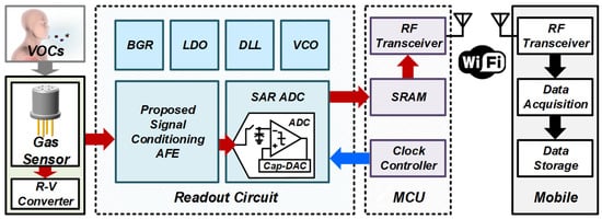
Figure 1.
Overall system architecture of the proposed portable gas sensor system.
3. Proposed ROIC Design and Wi-Fi Communication Scheme
3.1. Conventional Gas Sensor System
Figure 2 illustrates the signal processing flowchart of a conventional gas sensor readout, highlighting the major stages involved in converting the sensor output into digital form. The gas sensor acts as a variable resistor whose resistance varies with gas concentration, generating an output voltage (VGS). This voltage reflects the chemical reactions occurring on the sensor surface and serves as the input for the readout circuitry. However, VGS typically includes unwanted noise components such as power supply noise, ground fluctuations, and thermal noise. To mitigate these, a low-pass filter (LPF) removes high-frequency noise, producing a filtered signal (VIA_IN) suitable for amplification. This step is essential to preserve signal fidelity. The filtered signal is then amplified by an instrumentation amplifier (IA), which emphasizes the signal variation relative to a reference voltage. The resulting signal (VADC_IN) is adjusted to match the ADC’s input range, ensuring the optimal usage of ADC resolution. Finally, the ADC digitizes this analog signal (VADC_IN) into a digital output (DOUT), allowing further processing, storage, and communication via a microcontroller or other digital systems. A critical aspect of this signal chain is the alignment of the power supply voltage (VDD) with the operating range of the readout system. Proper VDD selection is essential to preserve the sensor’s full dynamic range. If the VDD is insufficient, the ADC may saturate when the sensor output exceeds its input range, causing signal clipping or loss. While increasing the VDD can mitigate this issue, it comes at the cost of higher power consumption—an unfavorable trade-off for portable applications. Commercial gas sensors often require high operating voltages (up to 15 V) [17], complicating integration with low-power systems. Despite these challenges, sensor development often prioritizes sensing performance without considering system-level constraints, leading to suboptimal integration and power inefficiencies.
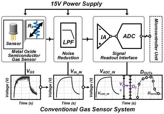
Figure 2.
Typical signal processing flowchart for gas sensor readout.
Furthermore, semiconductor gas sensors exhibit significant baseline variability between individual units and are sensitive to environmental conditions. To investigate this, a set of 50 TGS2600 gas sensor samples were tested under various temperature and humidity settings. Figure 3a shows the baseline distribution at a hydrogen concentration of 50 ppm and 45% relative humidity, as the temperature varies (10 °C, 20 °C, 30 °C). The x-axis represents initial baseline values; the y-axis represents mean absolute deviation (MAD) in LSBs (12-bit ADC, 3.3 V range). As temperature increases, MAD values become more dispersed: from a maximum of 50.9 LSB (mean: 41.7) at 10 °C, to 60.4 LSB (mean: 76.4) at 20 °C, and up to 99.5 LSB (mean: 124.3) at 30 °C. Similarly, Figure 3b presents the baseline variation under 50 ppm hydrogen and a fixed temperature (20 °C), while humidity varies from 40% to 85%. The MAD increases with humidity: 29 LSB (mean: 47.3) at 40% RH, 60.4 LSB (mean: 76.4) at 65% RH, and 126.9 LSB (mean: 81.7) at 85% RH. These results confirm that both temperature and humidity exacerbate baseline dispersion, introducing signal inconsistency. Figure 3c illustrates a major limitation of conventional portable gas sensor systems: the mismatch between the wide dynamic range of gas sensor outputs and the limited input range of ADCs. When the sensor output exceeds the ADC’s range (DMin to DMax), signal clipping occurs, resulting in data loss and degraded accuracy. Expanding the ADC range could mitigate this, but would necessitate higher supply voltages, leading to increased power consumption and cost. Moreover, such expansion often requires performance trade-offs. An alternative approach is to scale down the sensor output to fit within the ADC’s input range. However, this compromises the sensor’s sensitivity and resolution, limiting its ability to detect subtle concentration changes. Therefore, conventional methods either expanding the ADC input range or reducing the sensor signal magnitude struggle to maintain a high sensitivity under low-power constraints. These observations clearly underscore the need for advanced readout architectures that minimize data loss, preserve sensitivity, and maintain system efficiency across environmental variations and wide signal ranges.
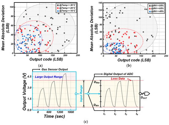
Figure 3.
Variation in gas sensor with (a) temperature and (b) humidity and (c) consideration of signal interfacing issue of portable gas sensor system structure.
3.2. Proposed Sensor System Structure
Figure 4 illustrates the architecture and operational principle of the proposed ROIC, which was designed for efficient signal acquisition from gas sensors. The ROIC is composed of two main components: an IA and an adaptive reference generator. The adaptive reference generator comprises four sampling switches (two ØRS1 and two ØRS2) and two sampling capacitors (CS1 and CS2). It operates in alternating odd [2n − 1] and even [2n] phases, enabling the continuous generation of reference voltages tailored to the input signal trajectory. The IA’s gain is programmable through a 3-to-8 decoder that selects among multiple gain resistors (RIG), allowing dynamic adjustment to accommodate various signal levels. Internally, the IA adopts a three-op-amp configuration, amplifying the difference between the filtered sensor output (VSO) and the reference voltage (VREF) generated by the adaptive reference generator, using a common-mode voltage (VCM) as the baseline. The amplified signal (VADC_IN) is then delivered to the ADC for digitization. The adaptive reference generation process operates as follows. During the odd phase (ØRS1), CS1 samples VSO to generate VREF [2n−1], while CS2 tracks VSO in preparation for the next even phase. During the even phase (ØRS2), CS2 samples VSO to generate VREF [2n], while CS1 tracks VSO to prepare VREF [2n−1] for the subsequent odd phase. This alternating mechanism produces reference voltages that continuously adapt to the input signal, enabling the IA to extract the differential signal ΔVSO = VSO − VREF with high temporal precision. This dynamic signal centering method significantly reduces the input range requirement of the ADC. As a result, a low-power ADC with a narrow input range can be employed, which decreases the overall power consumption and system cost. Furthermore, this approach preserves the original sensitivity of the gas sensor, as it avoids signal attenuation through analog scaling. The IA is equipped with an internal gain controller that enables flexible amplification or attenuation. This is implemented via a resistor-based digital-to-analog converter (DAC) structure [18], offering 3-bit control and eight selectable gain levels. This programmability enhances the adaptability of the ROIC across a variety of gas sensor types and signal magnitudes. Once the IA outputs the conditioned signal, it is digitized by the ADC and transferred to the MCU. A simple digital signal reconstruction algorithm is used to recover the original waveform from the digitized differential data. The following are illustrated in Figure 5:
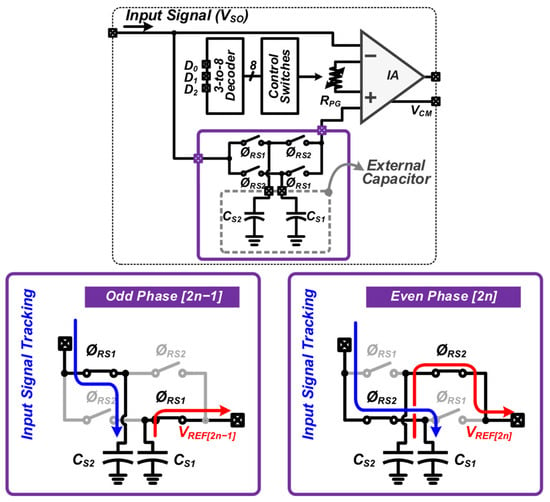
Figure 4.
Proposed ROIC structure and adaptive reference generator scheme.
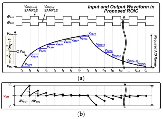
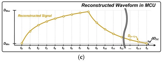
Figure 5.
(a) Gas sensor signal waveform and VREF creation timing. (b) Chopping VSO signal generated in ROIC. (c) Reconstructed waveform in MCU.
- Figure 5a: Shows the timing diagram of the two-phase sampling process. During each clock cycle (tn), the adaptive reference generator alternates between ØRS1 and ØRS2, generating VREF[n] for each respective phase.
- Figure 5b: Illustrates the computation of ΔVSO[n] = VSO[n] − VREF[n] at each phase. These values are then digitized and sent to the MCU.
- Figure 5c: Describes the reconstruction algorithm. If the previous data point at tn−1 is D[n−1], and the differential data at tn is ΔD[n], the reconstructed signal D[n] is obtained by D[n] = D[n−1] + ΔD[n]. This process iterates over successive samples, reconstructing a continuous waveform.
The main advantage of this method is its ability to reduce ADC dynamic range requirements without sacrificing signal fidelity. By adaptively referencing the input signal, the need for a high-range ADC is eliminated, resulting in substantial reductions in both power consumption and circuit complexity. This technique is particularly beneficial in gas sensor applications, where signal variations can be large and unpredictable. By integrating the proposed ROIC and the reconstruction algorithm, the system achieves enhanced energy efficiency, improved signal accuracy, and a simplified overall architecture, making it well-suited for portable, low-power, and cost-sensitive environments.
Figure 6 presents the overall block diagram of the proposed gas sensor system, detailing the signal processing flow and the roles of each subsystem. The system comprises two primary components: the ROIC and the digital control logic implemented within the MCU. These components work in concert to ensure accurate signal acquisition, minimal power consumption, and reliable digital reconstruction. The signal chain begins with the gas sensor output (VSO), which is first passed through the LPF to suppress high-frequency noise and external interference. The filtered signal is then processed by the adaptive reference generator, which alternates between odd and even sampling phases to dynamically generate reference voltages (VREFn). This mechanism allows the system to track variations in the sensor baseline and compress the signal swing prior to amplification. Next, the IA amplifies the differential signal ΔVSO, effectively centering the input relative to the reference and preparing it for A/D conversion. The conditioned signal is digitized by a low-power ADC and transmitted to the MCU via a parallel data bus. Within the MCU, the digitized output is first stored in SRAM, where it is processed using a lightweight digital reconstruction algorithm. This algorithm incrementally restores the original waveform by summing the differential data ΔD[n] with the previously reconstructed point D[n−1, m], thereby preserving the dynamic behavior of the sensor output. The reconstructed signal is then processed by a digital common generator and temporarily buffered before being transferred to a storage unit or communication interface for downstream processing. To ensure synchronized operation among the subsystems, the system utilizes a control bus architecture. The adaptive reference generator control unit produces the timing signals necessary for interleaved sampling, while the ADC control unit handles precise conversion timing. Additional units including the SRAM control and logic control blocks coordinate memory access and data transfer within the MCU. A system-wide master clock is provided by an on-chip oscillator (OSC) and phase-locked loop (PLL), which deliver stable and precise timing for all functional blocks. By tightly integrating the adaptive analog front-end with a low-power digital reconstruction flow, the proposed system effectively reduces the required ADC dynamic range and power consumption.
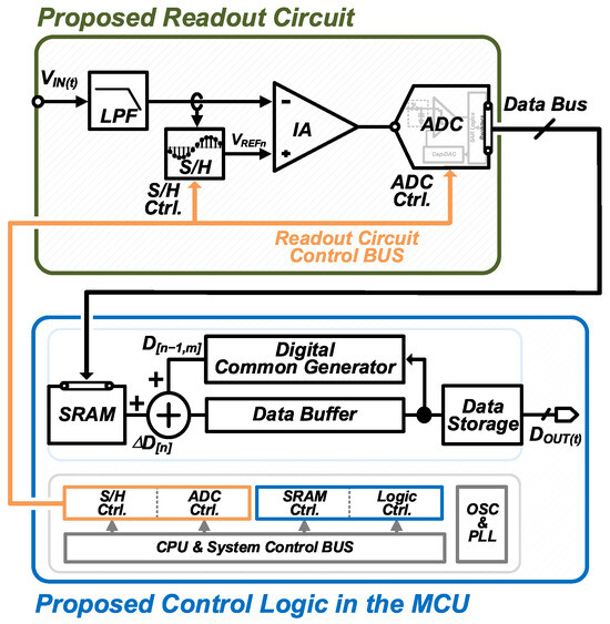
Figure 6.
Overall block diagram of the proposed gas sensor system.
3.3. Proposed Wi-Fi Communication Scheme
Figure 7 illustrates the timing diagrams for Wi-Fi communication and data readout across various MCU configurations: single-core/single-thread, single-core/multi-thread, and dual-core/multi-thread architectures [14,16]. These diagrams highlight the limitations associated with task concurrency in gas sensor systems and their impact on data integrity. In single-core/single-thread MCUs, Wi-Fi communication and data readout are executed sequentially. This constraint prohibits parallel task execution, often resulting in data loss when communication overlaps with signal readout. As shown in the timing diagram, communication delays commonly coincide with readout intervals, leading to unrecoverable signal loss. Consequently, this architecture is inadequate for real-time applications requiring continuous, accurate data acquisition. To mitigate these issues, single-core/multi-thread configurations allow the interleaved execution of tasks. This reduces data loss compared with single-threaded systems but still suffers from occasional contention due to the single-core limitation. As a result, performance remains suboptimal for applications requiring a high data throughput and minimal latency. In contrast, dual-core/multi-thread MCUs allocate separate cores to Wi-Fi communication and data readout, enabling true parallel processing. This architecture effectively eliminates data loss, as shown in the timing diagram, making it ideal for real-time sensing. However, dual-core solutions incur increased power consumption and production costs, which are less favorable for portable and energy-constrained systems. Although the proposed ROIC facilitates low-voltage signal extraction within a narrow dynamic range, the simultaneous execution of signal reconstruction and data transmission remains critical for maintaining system accuracy. The reconstruction algorithm relies on the incremental accumulation of extracted signal components. If the MCU fails to execute both signal processing and communication concurrently, the loss of critical data points, particularly the reference or boundary values, can significantly degrade the quality of reconstructed signals, compromising real-time monitoring. To address this challenge, the proposed communication scheme restructures task execution within the MCU to support single-core/single-thread operation without data loss. By optimizing task scheduling and reducing communication latency, the system ensures reliable signal reconstruction even under sequential processing constraints.
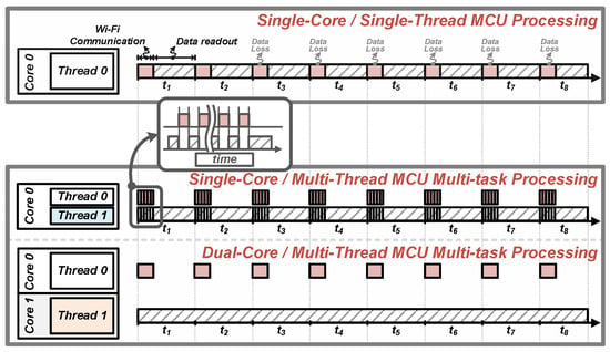
Figure 7.
Wi-Fi communication and data readout operations for various MCU configurations.
Figure 8 illustrates the proposed compensation strategy for mitigating data loss during Wi-Fi communication in single-core/single-thread MCUs. In conventional implementations, Wi-Fi communication is initiated at the beginning of each readout cycle, as shown in Figure 8a. This timing overlaps with signal acquisition, causing the loss of initial or mid-cycle data points. Since the reconstruction algorithm relies on the initial sample of each cycle as a reference voltage (VCM), missing this value prevents the accurate calculation of differential signal components (ΔVSO), introducing significant reconstruction error. Despite this, the ROIC possesses an inherent compensatory feature: since signal extraction is performed relative to VCM, subsequent samples still reflect accumulated changes even when intermediate values are missing. Building on this characteristic, the proposed strategy reschedules Wi-Fi communication to occur during the middle of each readout cycle, as illustrated in Figure 8b. This preserves the first and last data points, which are critical for maintaining signal continuity and reference alignment. To further address mid-cycle data loss, interpolation techniques are employed to estimate missing values. The waveform comparison in Figure 8b confirms that the proposed method yields a reconstructed signal closely matching the actual sensor output. In contrast, the conventional method shown in Figure 8a exhibits pronounced deviations due to unmitigated data loss. By strategically shifting the communication window and integrating interpolation-based compensation, the proposed scheme enables accurate signal reconstruction without requiring additional hardware resources. This ensures that low-power, low-cost single-core/single-thread MCUs remain viable for portable gas sensing applications, preserving energy efficiency without sacrificing signal fidelity.
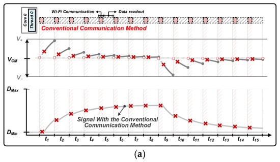
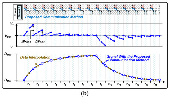
Figure 8.
(a) Data loss in conventional communication scheme and (b) proposed strategy for data loss compensation in single-core/single-threaded MCU.
4. Measurement Results and Discussion
Figure 9a illustrates the overall measurement system configuration and the flowchart of the testing procedure, while Figure 9b presents the actual experimental setup used to evaluate the proposed system’s hydrogen gas detection performance. The test environment comprises several key components: a mass flow controller (MFC) for gas flow regulation, a bubbler for humidity control, and a sealed chamber capable of accommodating multiple gas sensors simultaneously. The system uses hydrogen gas and clean air, with gas injection timing controlled via solenoid air valves managed by a system control PC. The PC also regulates the MFCs to precisely control gas concentrations inside the chamber. Humidity control is achieved using two separate clean air lines, each equipped with its own MFC. One pathway is connected to a bubbler, introducing moisture into the air stream. The humidified and dry air flows are then combined in controlled proportions to achieve the desired humidity level. Hydrogen gas is subsequently introduced and mixed with the conditioned air within a mixer unit, allowing the precise control of gas concentration, humidity, and clean air dilution. In this experiment, the hydrogen flow rate was set to 100 sccm, and the gas concentration was fixed at 100 ppm. Gas was injected for 500 s, followed by a 1200 s fresh air purging cycle to restore baseline conditions. All measurements were conducted in an indoor environment maintained at approximately 24 °C ± 2 °C and 50% relative humidity (RH). A 10 kΩ load resistor was applied to the sensor during testing. The total test duration was 3400 s, encompassing two complete sensing cycles. Also Figure 9b used the custom mobile application developed for the system, which enables real-time signal acquisition and user notifications. The app provides key functionalities such as live hydrogen concentration monitoring, threshold-based alert messaging, and automatic data logging for long-term tracking. This integration confirms the system’s ability to support real-time wireless communication and user feedback under practical usage scenarios. The PCB-level prototype used in the experiments measures 50 mm in width and 23 mm in height, as shown alongside a 19.5 mm coin for scale. Despite incorporating both the sensor readout circuit and the wireless communication module, the prototype maintains a compact form factor, demonstrating suitability for portable gas sensing applications.
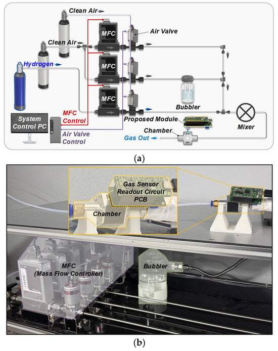
Figure 9.
(a) Measurement flowchart, (b) experimental setup environment.
Figure 10 shows the measured transient response of the proposed gas sensor system under controlled environmental conditions (50% RH, 24 °C). The experiment evaluates the system’s dynamic behavior during hydrogen gas injection and its capability to extract accurate gas concentration data in real time. Figure 10a presents the output of the instrumentation amplifier (VIA) during the injection phase. The baseline common-mode output voltage is approximately 0.74 V, with a noticeable voltage drop (ΔVIA) occurring in response to hydrogen exposure. This behavior corresponds to the alternating operation of the adaptive reference generator, which switches between odd and even readout phases at 3 s intervals. Following the end of the gas injection period, the introduction of fresh air leads to a gradual increase in VIA, indicating the sensor’s recovery and gas clearance. Figure 10b displays the real-time digital output (DOUT) reconstructed by the system. The waveform shows a clear separation between the gas injection and air purge phases, accurately reflecting the transient characteristics of the sensor signal. The ΔVIA values collected during measurement are translated into concentration data through digital reconstruction, verifying that the system provides high signal integrity and real-time monitoring capabilities suitable for practical applications.
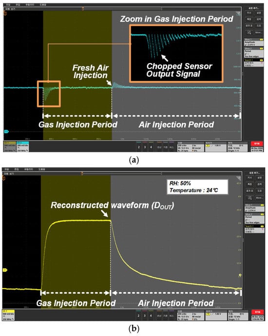
Figure 10.
(a) Transient response measurement of chopped sensor output and (b) result of proposed system.
Figure 11 provides a comparative analysis of hydrogen gas signal reconstruction under three different system configurations, all evaluated under the same environmental conditions (50% RH, 24 °C). Figure 11a shows the reference signal obtained using a conventional ROIC with a 3.3 V supply. The original hydrogen signal peaks at 3.04 V, demonstrating the full dynamic response of the gas sensor. This configuration requires a high supply voltage to prevent signal clipping and to maintain accuracy. Figure 11b demonstrates the limitations of a commercial ROIC operating at a reduced 1.2 V supply. Due to the constrained ADC input range, parts of the sensor signal exceed the dynamic range and become saturated. This leads to significant signal distortion and loss. For example, a 100 ppm hydrogen gas input may be interpreted as a 5 ppm signal, resulting in critical concentration estimation errors. These results underscore the challenge of using conventional architectures at low voltages, where signal compression or clipping severely impacts detection accuracy. In contrast, Figure 11c shows the digitally reconstructed signal obtained using the proposed system, also operating at 1.2 V. Unlike Figure 11b, the proposed approach preserves the full sensor response through adaptive signal extraction and reconstruction. The system maintains high fidelity even under low-power conditions, avoiding saturation while accurately tracking gas concentration changes. This comparison confirms the proposed system’s ability to operate with a reduced supply voltage and input range while maintaining signal accuracy. By minimizing the required ADC dynamic range through ROIC-level preprocessing, the system achieves significant reductions in power consumption and hardware complexity. These attributes make the architecture highly suitable for portable and battery-powered gas sensor applications, where energy efficiency and costs are critical.
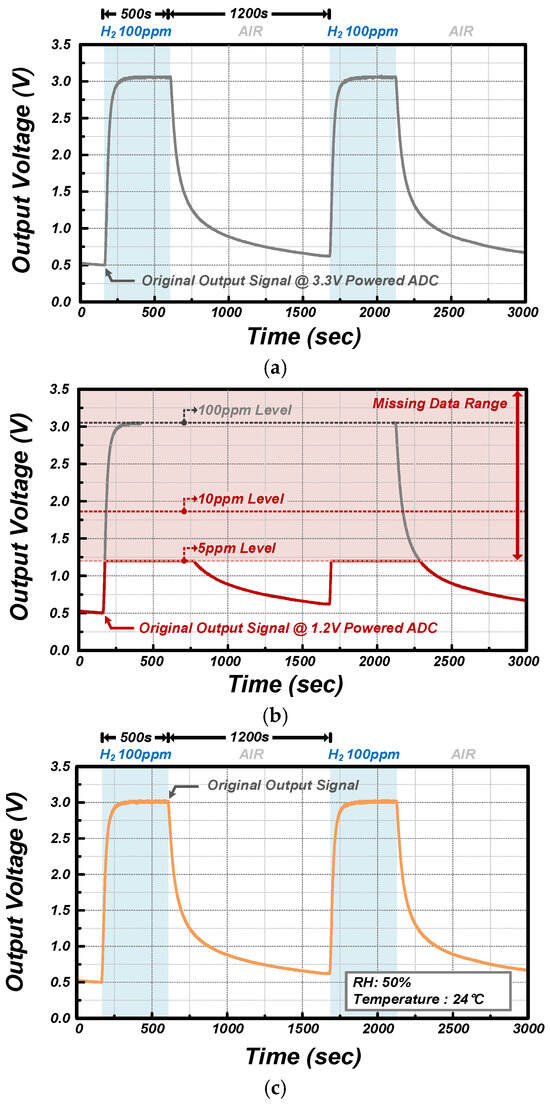
Figure 11.
Measured output signals: (a) conventional ROIC operating at 3.3 V power, (b) conventional ROIC operating at 1.2 V power, (c) proposed ROIC operating at 1.2 V power.
Figure 12 compares the reconstructed output waveforms obtained using the conventional communication method and the proposed communication algorithm, under identical environmental conditions. This evaluation focuses on signal integrity during wireless data transmission using a single-core/single-thread MCU architecture. Figure 12a illustrates the limitations of conventional Wi-Fi communication scheduling. Due to task conflicts, significant data loss occurs during signal readout, resulting in distorted waveform reconstruction. Specifically, the reconstructed signal exhibits a peak voltage of only 1.85 V, which is 1.19 V lower than the original 3.04 V reference signal, indicating a substantial error that can severely misrepresent the actual gas concentration. Figure 12b, in contrast, demonstrates the effectiveness of the proposed communication scheduling algorithm optimized for single-core/single-thread systems. By avoiding overlap between communication and critical signal acquisition intervals, the system preserves signal fidelity. The reconstructed waveform closely matches the original sensor signal, with a peak voltage deviation of only 0.15%, which is well within acceptable tolerance levels for real-time monitoring. These results confirm that the proposed algorithm reliably prevents signal degradation without requiring additional hardware, making it a practical and efficient solution for resource-constrained embedded systems.
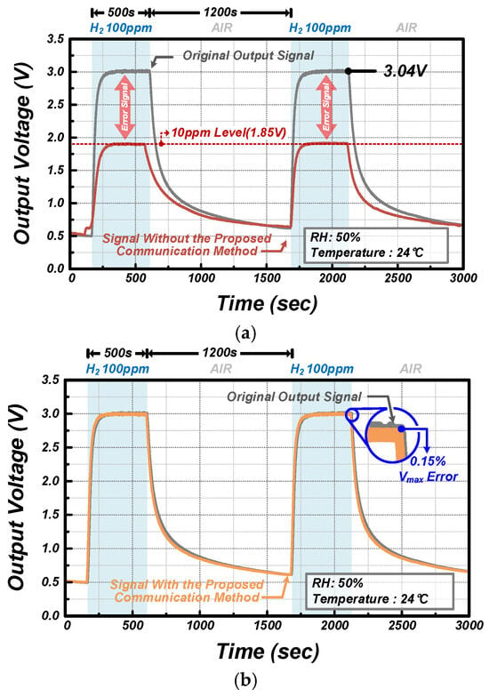
Figure 12.
Comparison output waveforms obtained using (a) conventional and (b) proposed communication method.
Figure 13a compares two commercially available ADCs operating at 3.3 V and 1.2 V supply voltages [19,20]. The 3.3 V ADC offers a wide input range but consumes 13.2 mW and costs approximately USD 30.44. In contrast, the 1.2 V ADC significantly reduces the power consumption to 0.22 mW and the cost to USD 13.20, but it suffers from a narrower input range, limiting its applicability in systems requiring large signal handling. The proposed ROIC overcomes this limitation by adaptively scaling the sensor signal to fit within the narrow input range of the 1.2 V ADC. As shown in previous experiments, this approach enables the use of low-power ADCs without sacrificing signal fidelity. Thus, high-end ADC performance can be approximated under significantly reduced power and cost constraints, improving overall system-level efficiency. Figure 13b presents a comparison of MCU intellectual property (IP) cores with varying core/thread configurations in terms of power consumption and cost [21,22,23,24,25,26,27,28,29,30,31,32]. Single-core/single-thread MCUs consume as little as 0.506 mW and cost USD 2.80, offering a highly efficient and cost-effective option for portable applications. In contrast, dual-core/multi-thread MCUs consume up to 1320 mW and cost USD 41.91, reflecting the trade-offs associated with higher performance architectures. Although single-core/single-thread MCUs offer exceptional efficiency, their inability to simultaneously handle data acquisition and wireless transmission can result in signal loss. This challenge is critical in gas sensor systems, where the accurate reconstruction of transient signals is essential. The proposed communication algorithm addresses this issue by timing data transmission during low-sensitivity intervals of the signal acquisition cycle. This scheduling ensures that essential data points are preserved and that overall signal fidelity is maintained. As a result, the system can leverage the advantages of low-cost, low-power MCU architectures while achieving performance levels comparable to those of high-end solutions.
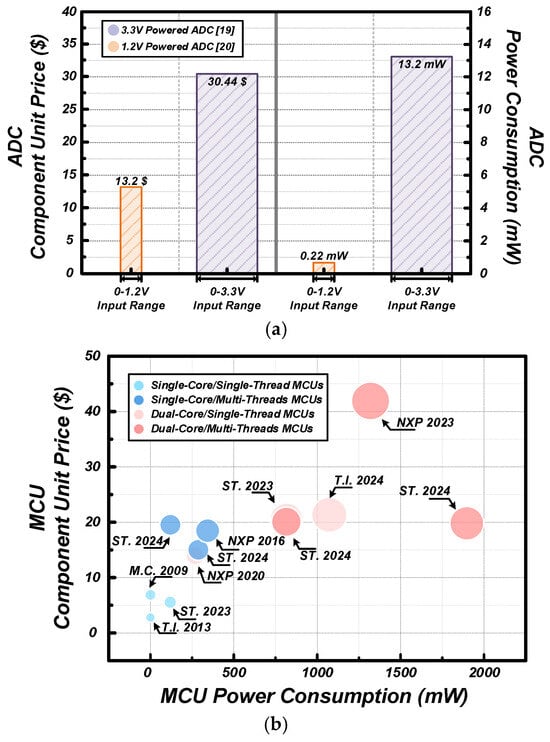
Figure 13.
Comparison of power consumption and cost by performance for (a) ADC [19,20] and (b) MCU [21,22,23,24,25,26,27,28,29,30,31,32].
Table 1 summarizes and compares the performance of the proposed gas sensor system with selected commercial products and research prototypes. The table presents key specifications, including MCU architecture, ADC characteristics, wireless communication methods, power consumption, and application suitability. The commercial product [33] adopts the same single-core/single-thread MCU architecture as the proposed system but operates at nearly twice the clock speed (180 MHz vs. 96 MHz). Although it utilizes a 12−bit ADC, its 3.3 V input range leads to a significantly higher power consumption compared with the proposed 1.2 V implementation. While functionally similar, this product is less favorable for portable or battery-powered environments due to its energy profile. Another commercial product [34] employs a multi-core/multi-thread MCU configuration, enabling concurrent signal conversion and data transmission. However, this architectural benefit comes at the cost of considerably increased power consumption, rendering it unsuitable for low-power sensing applications. Research prototypes [35] incorporate Bluetooth Low Energy (BLE) for wireless communication. BLE reduces power consumption relative to Wi-Fi; however, its limited communication range makes it less viable for extended-range portable applications. In contrast, the prototype proposed in [36] employs Wi-Fi communication, enabling longer-range connectivity, but its system design is optimized for general IoT usage rather than energy efficiency, resulting in higher overall power consumption. The proposed system achieves a favorable balance between performance and power efficiency by combining a 1.2 V ADC and a Wi-Fi-enabled MCU, while maintaining real-time monitoring, data logging, and alarm functions. Unlike the higher-cost commercial systems, the proposed design offers comparable functionality with significantly reduced power and manufacturing cost. This makes it particularly well-suited for portable biomedical gas sensing applications.

Table 1.
Performance summary and comparison.
5. Conclusions
This study proposed a cost-effective and energy-efficient portable gas sensor system based on a novel ROIC design and an optimized wireless communication algorithm. Experimental validation confirmed that the proposed system maintains high signal fidelity while significantly reducing power consumption and production cost. The integration of an adaptive signal extraction technique and a timing-optimized Wi-Fi communication scheme enables reliable real-time data transmission, even under resource-constrained conditions. The proposed architecture provides a scalable and practical solution for real-time gas sensing, offering a promising direction for the development of low-cost, high-performance environmental and healthcare monitoring technologies.
Author Contributions
Conceptualization, J.-N.K., S.-K.K., B.-C.P. and H.-J.K.; methodology, J.-N.K., S.-K.K., B.-C.P. and H.-J.K.; software, J.-N.K.; validation, J.-N.K. and S.-K.K.; formal analysis, H.-J.K.; investigation, J.-N.K., S.-K.K. and H.-J.K.; resources, J.-N.K., S.-K.K. and H.-J.K.; data curation, J.-N.K.; writing—original draft preparation, J.-N.K., S.-K.K., B.-C.P. and H.-J.K.; writing—review and editing, J.-N.K., B.-C.P. and H.-J.K.; visualization, J.-N.K. and S.-K.K.; supervision, H.-J.K.; project administration, H.-J.K.; funding acquisition, H.-J.K. All authors have read and agreed to the published version of the manuscript.
Funding
This research was supported by the Ministry of Science and ICT under grants RS-2023-00213402 and 2022M3I8A2079227.
Institutional Review Board Statement
Not applicable.
Informed Consent Statement
Not applicable.
Data Availability Statement
The data presented in this study are available on request from the corresponding author.
Acknowledgments
The EDA tool was supported by the IC Design Education Center.
Conflicts of Interest
The authors declare no conflicts of interest.
References
- Spirjakin, D.; Baranov, A.; Akbari, S. Wearable wireless sensor system with RF remote activation for gas monitoring applications. IEEE Sens. J. 2018, 18, 2976–2982. [Google Scholar] [CrossRef]
- Wang, J.; Wang, R. Development of Gas Sensors and Their Applications in Health Safety, Medical Detection, and Diagnosis. Chemosensors 2025, 13, 190. [Google Scholar] [CrossRef]
- Yu, W.; Mou, S.; Zhang, X.; Sun, J.; Xue, Y.; Xiong, H.; Hsia, K.J.; Wan, H.; Wang, P. Application of Sensing Devices in the Detection of Oral, Pulmonary, and Gastrointestinal Diseases. Chemosensors 2024, 12, 57. [Google Scholar] [CrossRef]
- Wang, Y.; Zhou, X.; Mao, S.; Chen, S.; Guo, Z. Challenges and Applications of Bio-Sniffers for Monitoring Volatile Organic Compounds in Medical Diagnostics. Chemosensors 2025, 13, 127. [Google Scholar] [CrossRef]
- Liewhiran, C.; Punginsang, M.; Inyawilert, K.; Siriwalai, M.; Wisitsoraat, A. Selectivity toward H2S against various gaseous disease markers in exhaled breath of flame-produced CuOx-loaded SnO2 nanosensors. Sens. Actuators B Chem. 2025, 424, 136856. [Google Scholar] [CrossRef]
- Kwon, S.-K.; Kim, J.-N.; Byun, H.-G.; Kim, H.-J. Low-power and cost-effective readout circuit design for compact semiconductor gas sensor systems. Electrochemistry Communications 2024, 169, 107834. [Google Scholar] [CrossRef]
- Supraja, P.; Tripathy, S.; Singh, S.G. Smartphone-powered, ultrasensitive, and selective, portable and stable multi-analyte chemiresistive immunosensing platform with PPY/COOH-MWCNT as bioelectrical transducer: Towards point-of-care TBI diagnosis. Bioelectrochemistry 2023, 151, 108391. [Google Scholar] [CrossRef] [PubMed]
- Righettoni, M.; Amann, A.; Pratsinis, S.E. Breath analysis by nanostructured metal oxides as chemo-resistive gas sensors. Mater. Today 2015, 18, 163–171. [Google Scholar] [CrossRef]
- Han, C.; He, X.; Wang, J.; Gao, L.; Yang, G.; Li, D.; Wang, S.; Chen, X.; Peng, Z. A low-cost smartphone controlled portable system with accurately confined on-chip 3D electrodes for flow-through cell electroporation. Bioelectrochemistry 2020, 134, 107486. [Google Scholar] [CrossRef] [PubMed]
- Suh, J.-H.; Cho, I.; Kang, K.; Kweon, S.-J.; Lee, M.; Yoo, H.-J.; Park, I. Fully integrated and portable semiconductor-type multi-gas sensing module for IoT applications. Sens. Actuators B Chem. 2018, 265, 660–667. [Google Scholar] [CrossRef]
- Kwon, S.-K.; Byun, H.-G.; Kim, H.-J. An Analog Adaptive Reference Generation Readout Integrated Circuit for Baseline-Free Gas Sensor Measurements. IEEE Trans. Instrum. Meas. 2024, 73, 1–8. [Google Scholar] [CrossRef]
- Song, Y.; Xue, Z.; Xie, Y.; Fan, S.; Geng, L. A 0.6-V 10-bit 200-kS/s Fully Differential SAR ADC with Incremental Converting Algorithm for Energy Efficient Applications. IEEE Trans. Circuits Syst. I Regul. Pap. 2016, 63, 449–458. [Google Scholar] [CrossRef]
- Sadollahi, M.; Hamashita, K.; Sobue, K.; Temes, G.C. An 11-Bit 250-nW 10-kS/s SAR ADC with Doubled Input Range for Biomedical Applications. IEEE Trans. Circuits Syst. I Regul. Pap. 2018, 65, 61–73. [Google Scholar] [CrossRef]
- Espressif Systems, Esp32-H2 Series Datasheet V1.0. 2024. Available online: https://www.espressif.com/sites/default/files/documentation/esp32-h2_datasheet_en.pdf (accessed on 1 March 2025).
- FIGARO USA, INC. Tgs2600—For the Detection of Air Contaminants. 2022. Available online: https://www.figarosensor.com/product/docs/tgs2600_product%20information%28fusa%29_rev05.pdf (accessed on 28 April 2025).
- ASA, N.S. nRF7002 Product Specification v1.2. 2024. Available online: https://docs.nordicsemi.com/bundle/ps_nrf7002/page/keyfeatures_html5.html (accessed on 5 February 2025).
- Zhengzhou Winsen Electronics Technology Co., Ltd. Mq5 Flammable Gas Sensor. 2018. Available online: https://www.winsen-sensor.com/d/files/MQ-5.pdf (accessed on 5 March 2025).
- Lu, C.W.; Yin, P.Y.; Hsiao, C.M.; Chang, M.C.F.; Lin, Y.S. A 10-bit Resistor-Floating-Resistor-String DAC (RFR-DAC) for High Color-Depth LCD Driver ICs. IEEE J. Solid-State Circuits 2012, 47, 2454–2466. [Google Scholar] [CrossRef]
- Analog Devices, Inc. Ad7853. 1998. Available online: https://www.analog.com/media/en/technical-documentation/data-sheets/AD7853_7853L.pdf (accessed on 29 November 2024).
- Texas Instruments Inc. Ads7866. 2005. Available online: https://www.ti.com/lit/ds/symlink/ads7866.pdf?ts=1738160906577&ref_url=https%253A%252F%252Fwww.ti.com%252Fproduct%252Fko-kr%252FADS7866 (accessed on 29 November 2024).
- Texas Instruments Inc. Msp430g2553ipw20r. 2013. Available online: https://www.ti.com/lit/ds/symlink/msp430g2553.pdf?ts=1738112890202&ref_url=https%253A%252F%252Fwww.google.com%252F (accessed on 23 January 2025).
- STMicroelectronics. Stm32f103c8t6. 2023. Available online: https://www.st.com/resource/en/datasheet/cd00161566.pdf (accessed on 23 January 2025).
- Microchip Technology Inc. Pic18f4550. 2009. Available online: https://ww1.microchip.com/downloads/aemDocuments/documents/OTH/ProductDocuments/DataSheets/39632e.pdf (accessed on 23 January 2025).
- STMicroelectronics. Stm32f407vgt6. 2024. Available online: https://www.st.com/resource/en/datasheet/dm00037051.pdf (accessed on 24 January 2025).
- STMicroelectronics. Stm32f429zit6. 2024. Available online: https://www.st.com/resource/en/datasheet/stm32f427vg.pdf (accessed on 24 January 2025).
- NXP Semiconductors. Mk64fn1m0vll12. 2016. Available online: https://www.nxp.coms/docs/en/data-sheet/K64P144M120SF5.pdf (accessed on 24 January 2025).
- NXP Semiconductors. Lpc4370fet100. 2020. Available online: https://www.nxp.com/docs/en/data-sheet/LPC4370.pdf (accessed on 24 January 2025).
- STMicroelectronics. Stm32h745zit6. 2019. Available online: https://www.mouser.kr/datasheet/2/389/stm32h745zg-1760969.pdf (accessed on 24 January 2025).
- Texas Instruments Inc. Tms320f28377dptpt. 2024. Available online: https://www.ti.com/lit/ds/symlink/tms320f28377d.pdf?ts=1738165054974&ref_url=https%253A%252F%252Fwww.mouser.kr%252F (accessed on 25 January 2025).
- STMicroelectronics. Stm32mp157caa3. 2020. Available online: https://www.mouser.kr/datasheet/2/389/stm32mp157c-1588851.pdf (accessed on 25 January 2025).
- STMicroelectronics. Stm32h757iit6. 2022. Available online: https://www.mouser.kr/datasheet/2/389/stm32h743vi-1760857.pdf (accessed on 25 January 2025).
- NXP Semiconductors. Mvf61ns151cmk50. 2023. Available online: https://www.nxp.com/docs/en/data-sheet/VYBRIDFSERIESEC.pdf (accessed on 25 January 2025).
- MIKROE. Wifi 4 Click Module. 2018. Available online: https://www.mikroe.com/wifi-4-click (accessed on 16 February 2025).
- Apollo Automation. Air-1 Air Quality Sensor for Home Assistant. 2023. Available online: https://apolloautomation.com/products/air-1 (accessed on 16 February 2025).
- Anik, S.M.H.; Gao, X.; Meng, N.; Agee, P.R.; McCoy, A.P. A cost-effective, scalable, and portable IoT data infrastructure for indoor environment sensing. J. Build. Eng. 2022, 49, 104027. [Google Scholar] [CrossRef]
- Seok, C.; Mahmud, M.M.; Kumar, M.; Adelegan, O.J.; Yamaner, F.Y.; Oralkan, Ö. A Low-Power Wireless Multichannel Gas Sensing System Based on a Capacitive Micromachined Ultrasonic Transducer (CMUT) Array. IEEE Internet Things J. 2019, 6, 831–843. [Google Scholar] [CrossRef]
Disclaimer/Publisher’s Note: The statements, opinions and data contained in all publications are solely those of the individual author(s) and contributor(s) and not of MDPI and/or the editor(s). MDPI and/or the editor(s) disclaim responsibility for any injury to people or property resulting from any ideas, methods, instructions or products referred to in the content. |
© 2025 by the authors. Licensee MDPI, Basel, Switzerland. This article is an open access article distributed under the terms and conditions of the Creative Commons Attribution (CC BY) license (https://creativecommons.org/licenses/by/4.0/).