Article

Variability Assessment of the Performance of MoS2-Based BioFETs

Departamento de Electrónica y Tecnología de Computadores, Facultad de Ciencias, Universidad de Granada, 18071 Granada, Spain
*
Authors to whom correspondence should be addressed.
Chemosensors 2023, 11(1), 57; https://doi.org/10.3390/chemosensors11010057
Submission received: 23 November 2022 / Revised: 23 December 2022 / Accepted: 2 January 2023 / Published: 10 January 2023
(This article belongs to the Collection pH Sensors, Biosensors and Systems)

Abstract

:
Two-dimensional material (2DM)-based Field-Effect Transistors (FETs) have been postulated as a solid alternative for biosensing applications thanks to: (i) the possibility to enable chemical sensitivity by functionalization, (ii) an atomically thin active area which guarantees optimal electrostatic coupling between the sensing layer and the electronic active region, and (iii) their compatibility with large scale fabrication techniques. Although 2DM-based BioFETs have demonstrated notable sensing capabilities, other relevant aspects, such as the yield or device-to-device variability, will demand further evaluation in order to move them from lab-to-fab applications. Here, we focus on the latter aspect by analyzing the performance of MoS 2 -based BioFETs for the detection of DNA molecules. In particular, we explore the impact of the randomized location and activation of the receptor molecules at the sensing interface on the device response. Several sensing interface configurations are implemented, so as to evaluate the sensitivity dependence on device-to-device variability.

1. Introduction

In the context of the Internet of Things (IoT), the possibility to continuously monitor information from the environment and translate it into electrical signals, that can be easily processed and stored, has become a present and ubiquitous reality. Among the myriad of signals to be sensed, those connected with human healthcare, or in a more general perspective with bio-activity, occupy a prime position [1]. There exists, indeed, a relentless demand for the design and optimization of accurate and robust electronic bio-sensors able to gather and process information of varied sources in real-time.
In this scenario, Biomolecular Field-Effect Transistors (BioFETs) are expected to play a key role, prevailing over other sensing alternatives thanks to: (i) a quick and label-free operation [2], (ii) high sensitivity and selectivity [3,4], and (iii) the capability to measure in vivo [5] and even real-time [6] signals. Although the first demonstration of these devices dates back to the 1970s [7], BioFETs implementation over the last decades has been hindered by a complex and unsolved trade-off between increased sensitivity and compatibility with large scale fabrication. The sensitivity was, indeed, boosted in the beginnings of the century thanks to the use of nanowire structures [8,9,10], due to their optimized surface-to-volume ratio. However, their widespread deployment was compromised by a difficult mass-scale production and integration with planar technology [11]. The appearance of two-dimensional materials (2DMs) around two decades ago opened new possibilities to reach the best balance between the two facets [12,13]: 2DMs represent the optimal surface-to-volume ratio structural arrangement, while their integration with current thin-film fabrication processes is feasible [14,15]. Moreover, a large variety of 2DMs can be synthesized [16], showing insulating, metallic or semiconducting behavior while the weak inter-layer forces that hold them together can be harnessed to seamlessly stack them in so-called van-der-Waals heterostructures, opening a wide variety of possibilities to be explored [17].
In this roadmap for the development of 2DM-based BioFETs, computational tools are called to play a key role to: (i) better understand the physical mechanisms that govern their behavior, and (ii) serve as a guide for faster device optimization enabling the lab-to-fab gap closure. Several approaches have been exploited for the latter which are based either in TCAD [18,19,20] or ad-hoc simulation tools [21,22,23,24,25], that are however not able to deal with essential aspects of mass-scale production such as reproducibility and device-to-device variability. This essential step, mandatory to increase the technology readiness level and prepare the leap from research to manufacture, demands an early performance evaluation with computational tools capable to reproduce heterogeneous device architectures, scenarios and operations. To that end, we present an improved numerical tool for 2DM-based BioFETs [26] that enables a comprehensive evaluation of the sensor variability through the impact in the device response of an arbitrary receptor distribution along a sensing interface. The capabilities of the proposed approach will be exemplified with the study of MoS 2 -based BioFETs aiming for the detection of DNA molecules. Different receptor distributions and activation configurations will be considered to assess the sensor electrical read-out robustness against variability. Devices employed for this study are assumed to be identical in their I–V characteristics, and the only source of variability is originated by the receptor molecules.
The rest of this work is organized as follows: Section 2 describes the simulation model, while the details of the simulated device and the results obtained for different receptor configurations are collected in Section 3. Finally, Section 4 sums up the main conclusions.

2. Materials and Methods

The implemented numerical tool self-consistently solves the Poisson and continuity equations in the sensor and its environment. The electrolyte corresponds to a Phosphate Buffer Saline (PBS) solution, whose regulatory chain of reactions—dependent on ionic strength and temperature—are described in [26], while the ion concentration is determined by the modified Boltzmann equation, including steric effects due to the finite size of the ions. This numerical tool has been previously validated with experimental results at the levels of the semiconductor device [27,28], the sensing interface [29], and the complete BioFET device [26]. DNA is selected as the analyte of interest due to their relevance in numerous biological processes, although this study could be extended to other biomolecules [29]. The DNA receptor and target sequences are modeled taking into consideration the individual shape and charge distribution of the DNA chains (Figure 1), what is by itself a notable step-forward in the modeling of DNA sensing, substantially upgrading conventional charge-box models [18]. In more detail, the receptor molecules (attached to the device sensing surface) are single-stranded DNA (ssDNA) molecules, whose complementary nucleotide sequence (target molecule) is to be detected, as in conventional DNA sensors. These molecules are assumed to be disposed along the device surface with a vertical orientation. Other molecules orientations with respect to the sensing surface, i.e., with a certain tilting angle, could be considered, although it has been demonstrated in earlier studies that they do not result in significant changes in the sensing layer surface potential [30]. Once the complementary ssDNA is captured, it forms a double-stranded (dsDNA) molecule with the receptor attached to the sensing interface (Figure 1a). The actual charge and size of the receptor and target molecules depend on the number of nucleotides in the sequences. For ssDNA molecules, each nucleotide contributes to 1 e charge (where e is the electron elementary charge) and has a length of ∼0.34 nm. For dsDNA molecules, the charge per nucleotide is 2 e and the length is kept unaltered [31] (Figure 1c). It is worth it to note that the ssDNA is flexible, while the dsDNA has a compact rigid structure, a feature also included in the model, where the electrolyte ions are allowed to permeate and mix with ssDNA molecules while they are kept out of the spatial region occupied by dsDNA molecules (Figure 1b).
The impact of the receptor allocation in the sensor variability is evaluated considering different spatial distributions and activations of the ssDNA chains according to two scenarios (Figure 1d): (i) a uniform spacing between receptors ( d u ) along the sensing layer length ( L C h n ), which is used as a reference; and (ii) a random distribution where the distance between nearby receptors ( d k ) pivots around the uniform spacing as d k = d u + λ ( x ) N ( 0 , 1 ) , where N ( 0 , 1 ) is a half-normal distribution with unity variance and λ ( x ) = λ d 1 exp 1 2 x μ α L C h n 2 is a factor determining the amplitude of this random position correction to the uniform spacing. Here, μ and α control the amplitude and variance of the random correction, which eventually resembles a Gaussian distribution.
Once the position of the receptors is determined, their state (idle or activated) is set according to an activation probability ( 0 % P 100 % ). Thus, for a given number of receptor molecules (N) in the sensing layer, the number of activated receptors is given by N act = P N . The assignment of activated receptors for a given P value can be set: (i) uniformly, following a certain spatial frequency, or (ii) randomly, being the activation of each receptor equally probable. In this way, we can extend the study of different receptor spatial distributions (which roots in distinct fabricated devices) also to varying receptor activation configurations (which correspond to different operation conditions in a single device). Examples of both degrees of freedom are shown in Figure 1e.

3. Results

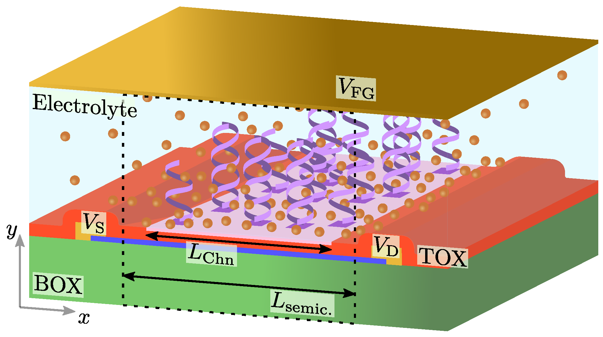
In order to exemplify the capabilities of the proposed approach to evaluate the impact of the variability of the sensing interface in the response of 2DM-based BioFETs, we have focused on a MoS 2 -based DNA-sensor. More specifically, the structure is defined by a MoS 2 monolayer (0.65 nm-thick and 50 cm 2 / Vs carrier mobility) with length L semic = 400 nm, sandwiched between a t box = 20 nm-thick SiO 2 layer, acting as a substrate, and a t ox = 10 nm-thick SiO 2 top-oxide layer. Above this latter one, a sensing layer of L C h n = 300 nm length is placed. For this channel length, and assuming low contact resistance, we can consider that the device performance is controlled by the channel properties rather than any contact effects, as probed by [32,33]. A number of N = 12 ssDNA receptors are allocated along the sensing interface, either uniformly or following the aforementioned random spatial distribution, with λ d = 0.5 nm, μ = 50 , 200, 350 nm, and α = 1 / 8 . The electrolyte is defined by a PBS solution, with composition [NaCl] = 140 mM, [KCl] = 2.7 mM and [NaH 3 PO 4 ] = 10 mM, regulating a pH of 7.4 . An schematic depiction of the structure under study is shown in Figure 2.
The electrical operation of the device is studied for a drain-to-source voltage of V DS = 0.1 V and a varying bias of the reference electrode immersed in the electrolyte ( V FG ). From the drain-to-source current ( I DS ), it is possible to define the device sensitivity (S) at a certain activation probability (P), as:
S ( P ) = I DS ( 0 % ) I DS ( P ) .
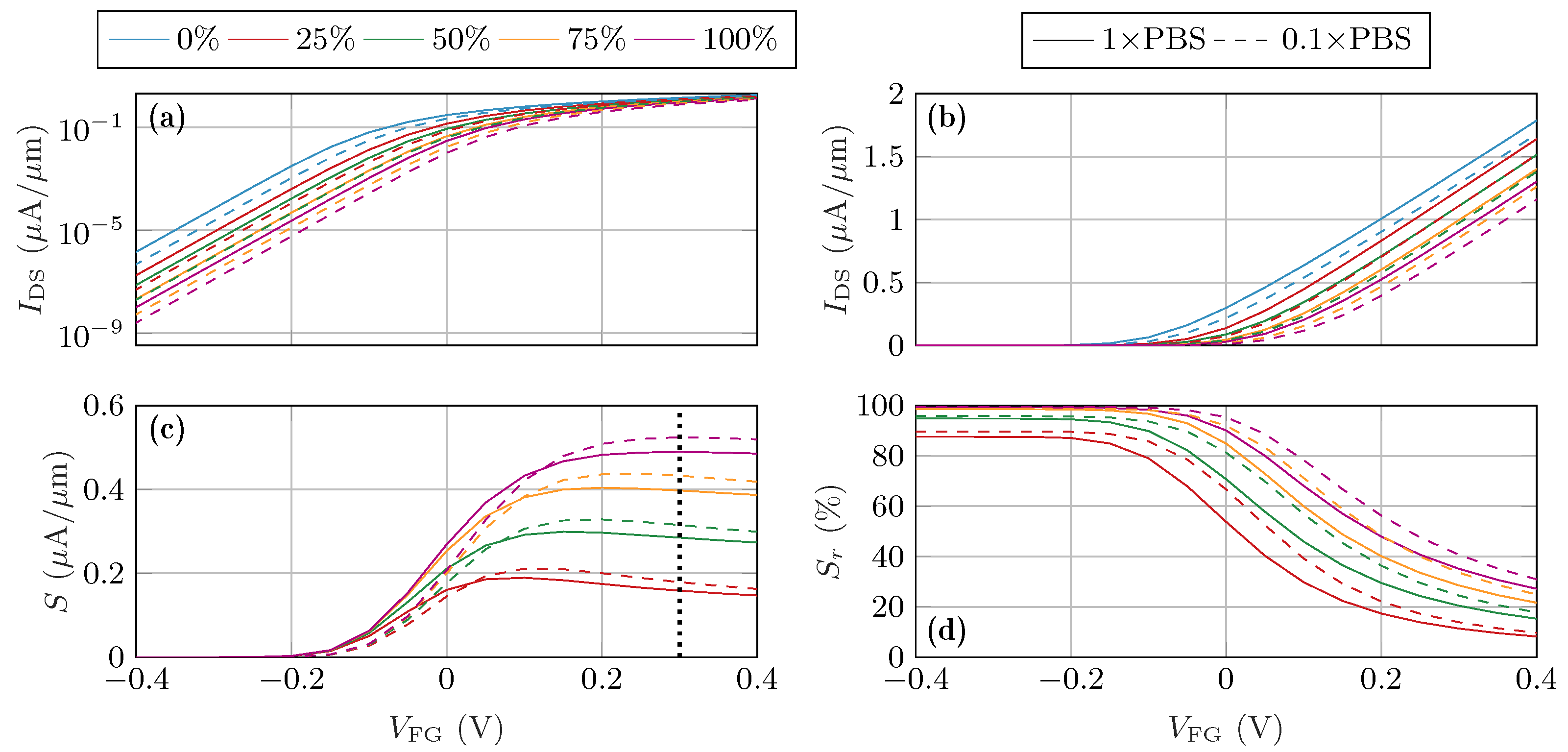
where I DS ( P ) stands for the output current calculated with an activation probability P. The I DS V FG and S V FG electrical read-outs as a function of P are depicted in Figure 3 for the scenario where the receptors are uniformly distributed, for two different PBS concentrations. The increase in P results in a shift of the transfer curves (Figure 3b) towards positive gate biases, due to the electrostatic repulsion that the negatively charged dsDNA molecules produce in the 2DM electron charge. When the ionic strength of the electrolyte is reduced, i.e., when we move from a 1×PBS electrolyte to a 0.1×PBS electrolyte, the Debye length of the electrolyte ions increases from λ D = 0.74 nm to λ D = 2.34 nm. Thus, the capability of the electrolyte to screen the dsDNA charges is reduced. As a consequence, the impact of the charged dsDNA molecules in the 2DM channel is enhanced. These effects can be also appreciated in the sensitivity curves (Figure 3c), that notably saturate for high V FG values, when the change in the carrier concentration in the channel (and therefore in I DS ) is no more significantly impacted by the dsDNA molecules. Note that sensitivity is usually referred in the literature as a value relative to the current in the absence of any binding event of the target antigen, i.e., S r ( P ) = I DS ( 0 % ) I DS ( P ) / I DS ( 0 % ) [34,35] (see Figure 3d). When defined in this way, S ( P ) maximum values correspond to the operation of the BioFET in the sub-threshold regime, where the sensor current is very low ( I ds pA/ μ m, see Figure 3a). The BioFET variability response in this regime, in a realistic experimental scenario, would be blurred by the noise background or limited by the lower limit sensitivity of the employed measuring equipment. For this reason, in order to investigate the random activation and distribution of single receptors and their impact in the variability, the absolute difference of the sensor output currents was considered as the sensor sensitivity definition (see Figure 3c).
In order to compare the sensitivity in different distribution and activation scenarios, we set an operating bias point at V FG = 0.3 V, which corresponds to the value where S ( P = 100 % ) is maximum. At this operating point, we have analyzed two sources of device-to-device variability: (i) the receptors spatial distribution, that accounts for different receptor location configurations, and (ii) the receptors activation distribution, that considers different configurations to activate the receptor molecules for a fixed P value. Figure 1e illustrates both scenarios.

3.1. Randomized Distribution Variability

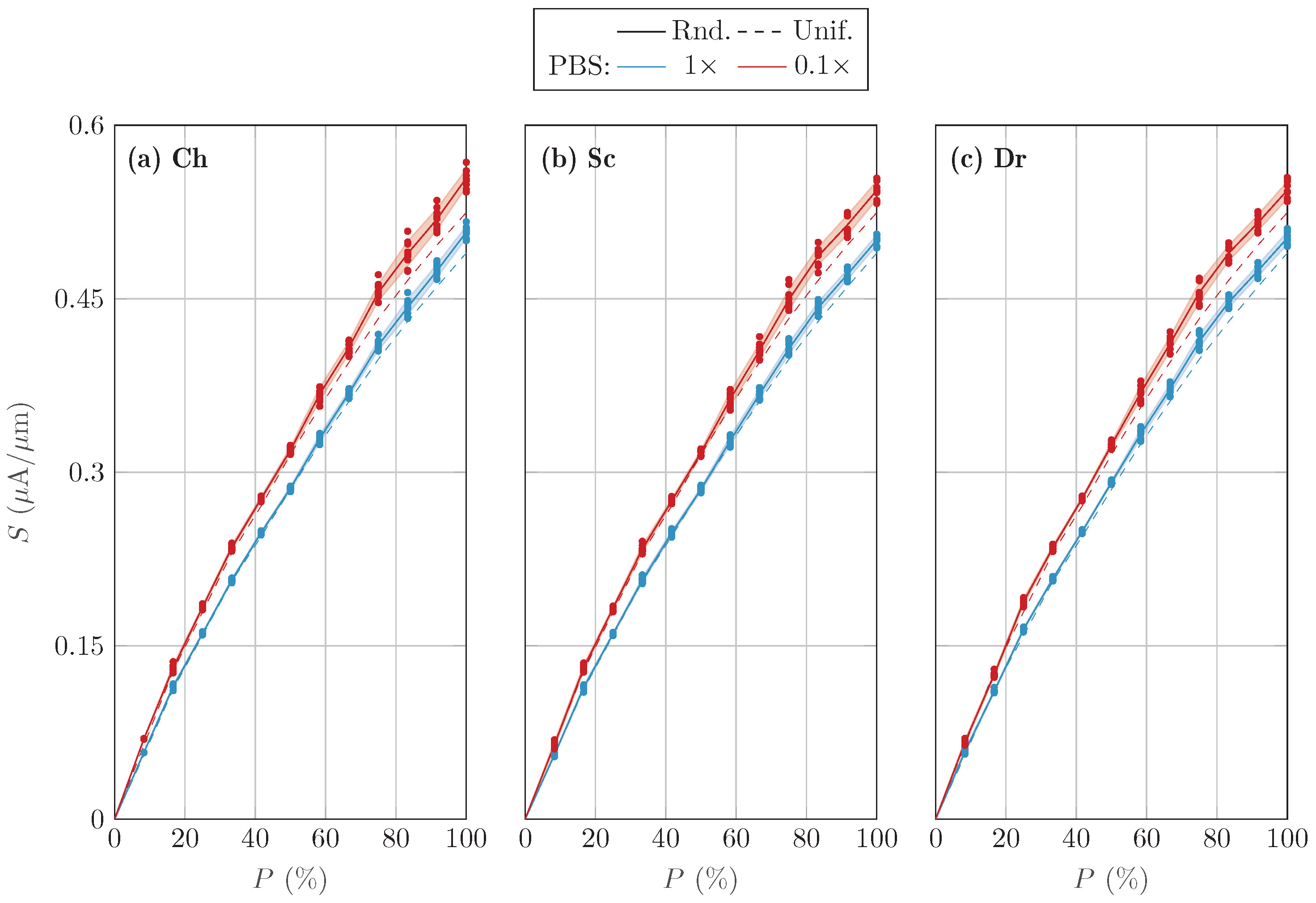
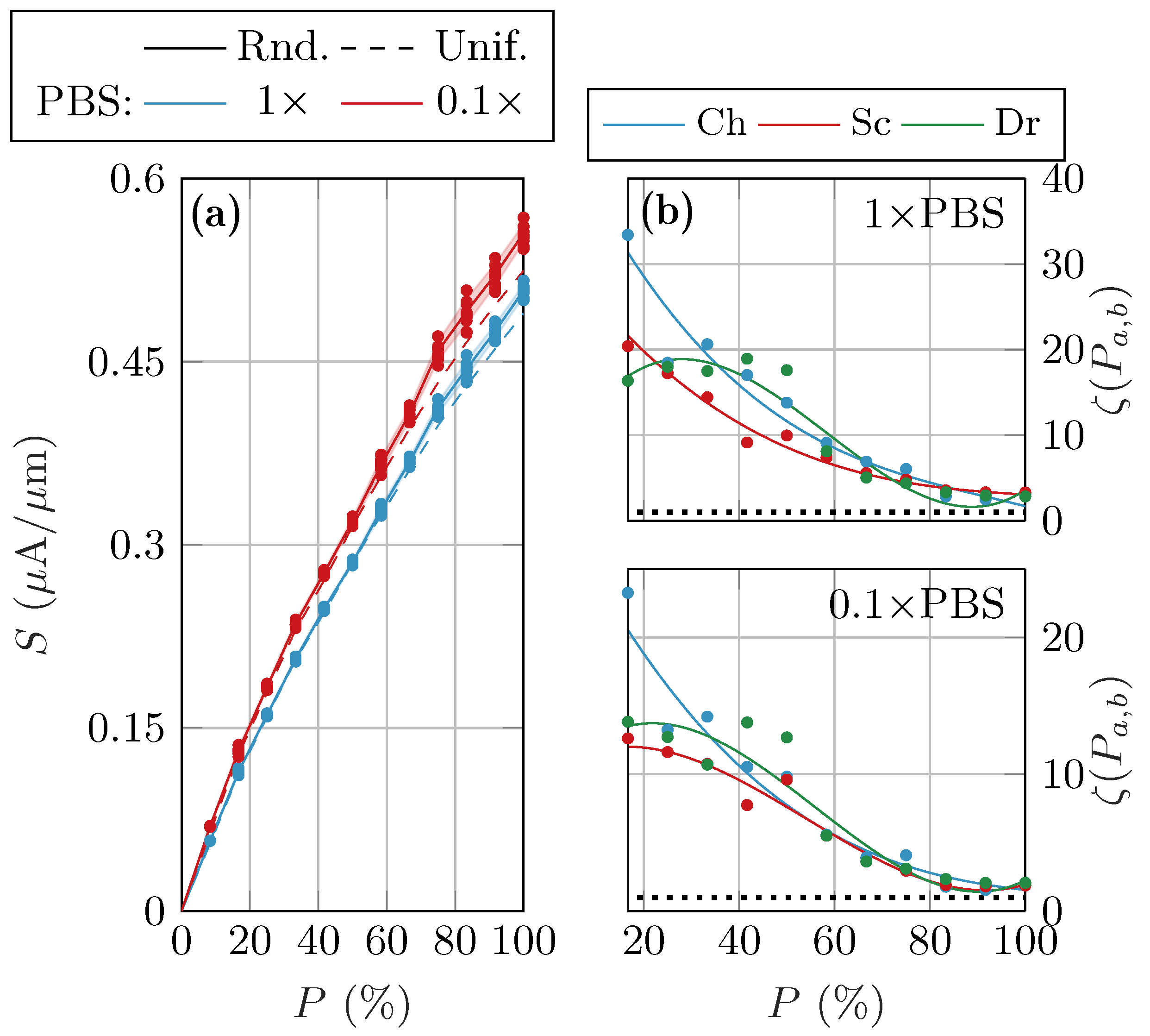
Three main scenarios were analysed for the randomized location of the receptors in the sensing layer: channel-centered (Ch), source-shifted (Sc) and drain-shifted (Dr). Ten different receptor distributions are generated for each of them. The three cases resulted in a similar behavior in terms of variability (see Appendix A Figure A1). Thus, for the sake of clarity, we have mostly focused on one of them: the channel centered. From the set of S values obtained in the different random distributions, we calculated the standard deviation σ S and mean value S that characterize the set. Figure 4a shows S as a function of the activation probability (solid lines), with the different S values marked with symbols and σ S plotted as a shadowed region around S . The results are compared with those of a uniform distribution of receptors for two PBS concentrations (dashed lines). The differences between the uniform distribution and the mean behavior of the randomized distributions is more acute as P increases, with the randomized distribution outperforming the uniform distribution for all P values. Although the number of activated receptors is the same, when the receptors are randomly distributed with a higher concentration at the centre of the channel, they are closer to each other and the ions diluted in the electrolyte have a reduced screening impact. Moreover, σ S increases with P due to the higher effective charge of the activated receptors. In fact, their remarkable influence in the drain current enhance the effect of the distribution randomness. As for the PBS, a lower value results in a higher Debye length, λ D , which translates into a lower electrolyte screening and a higher S for all cases, but at the cost of a higher variability, σ S .
One key criterion to characterize the role of the variability in the sensor response is the minimum change in the activation of the receptors that can be detected without being blurred by the variability of the response, i.e., by σ S . If the difference between S ( P a ) and S ( P b ) (i.e., the sensitivity mean values for a set of distributions with two P values) is smaller than the addition of their standard deviations, σ S ( P a ) and σ S ( P b ) , the activation probabilities P a and P b cannot be discerned in a reliable manner. The ratio of these two magnitudes provides a clear idea of the resolution of the sensor with respect to the variability:
ζ ( P a , b ) = S ( P a ) S ( P b ) σ S ( P a ) + σ S ( P b ) .
A value of ζ greater than 1 assures a bijective relation between sensitivity and activation percentage for these two values P a and P b . Of course, the closer P a and P b are, the lower the value of ζ . Here, we have studied the case where P b = P a ± 1 12 . Figure 4b shows ζ for the three random distribution cases and the two values of PBS. ζ decreases with P as a consequence of the higher variability observed, but in all cases is substantially above 1 when P < 80 % . Only at very high activation percentages the ζ value approximates the limit. When comparing the different molecule distributions, i.e., source-, channel- and drain-centered, we observe that the channel-centered distribution yield a higher ζ value. This is due to the effect of the source and drain contact biases, which electrically attract the ions in the electrolyte closer to the sensing interface, rising the screening capability of the electrolyte in these areas and reducing the sensor sensitivity. The molecule receptors located in the middle of the channel, on the contrary, are surrounded by ions free of such electrostatic attraction.

3.2. Randomized Activation Variability

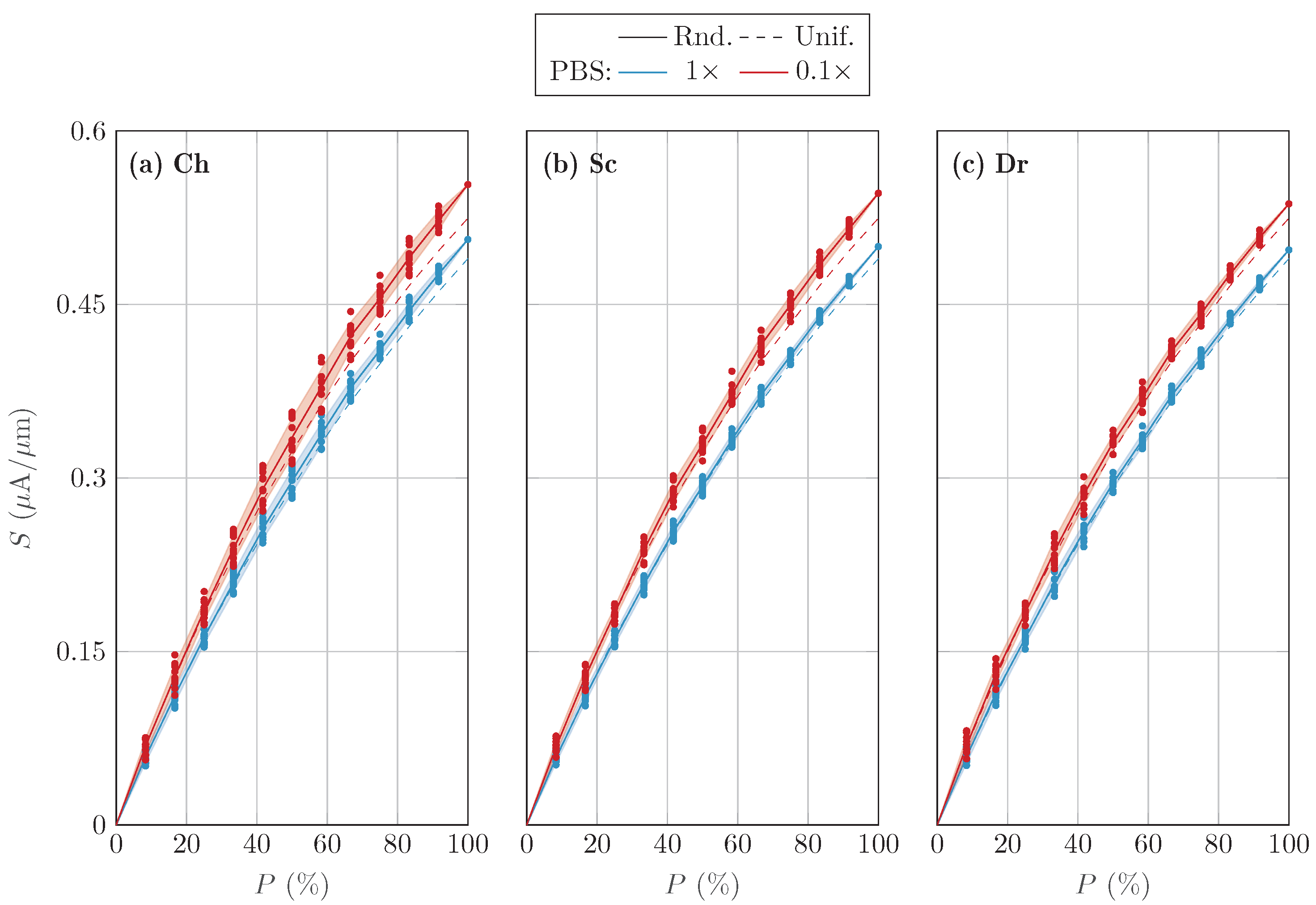
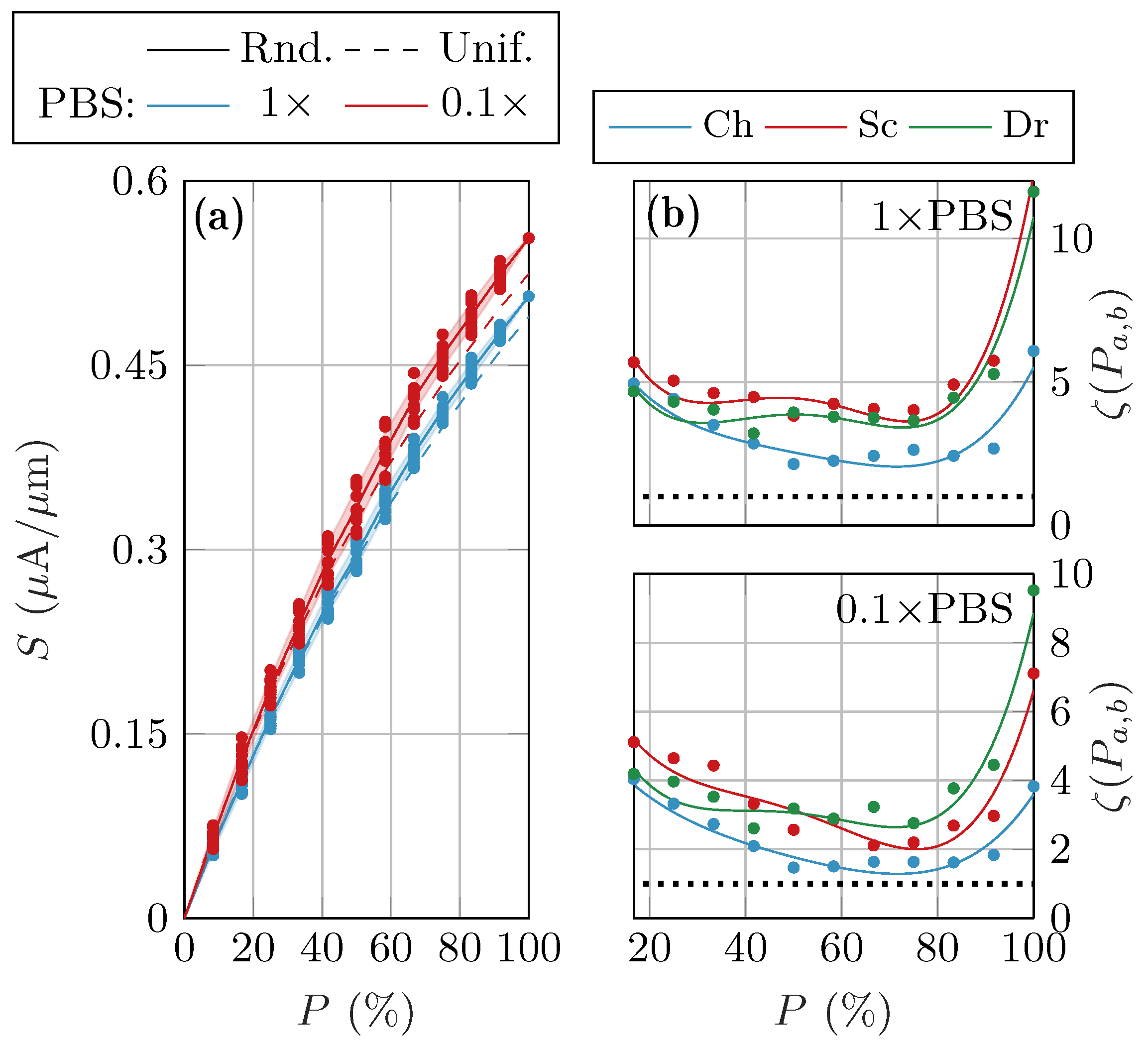
For a single fabricated device with a given distribution of N receptors, among which N act of them are activated, there are N N act = N ! N act ! ( N N act ) ! possible activation combinations, where N N act = 1 for both P = 0 % and P = 100 % , and it is maximized for N act = N / 2 . Among all possible combinations, twelve different activated receptors configurations for each value of P were selected (when possible). This activation variability was studied for the three distribution scenarios, namely, channel-centered, source-shifted and drain-shifted, and the results compared with a uniform distribution (see Appendix A Figure A2). Again, we considered 1×PBS and 0.1×PBS electrolytes for the sake of completeness.
Figure 5a compares S for the channel-centered scenario and the uniform receptor distribution, with each activation combination represented by a symbol and σ S plotted as a shadowed region. The trend of S with P and the PBS concentration and its comparison with the uniform distribution cast similar conclusions as in the previous subsection. The behavior of σ S , however, is conditioned by the actual possible combinations that N and N act allow, being 0 at P = 0 % and P = 100 % and broadening at N act = N / 2 . Finally, ζ has also been studied as a function of the activation probability (Figure 5b). While it keeps far from 1 at low and high P values, it evidences low values in the intermediate P range, when the amount of activation combinations is large. When comparing the behavior of ζ with the previous random distribution study (Figure 4b), it can be observed that the resolution of the sensor is compromised at different activation percentages in each case: only for very large activation percentages in the former case, and for intermediate values in the latter one, evidencing that the prevalence of the random receptor activation or their location in the variability of the sensor sensitivity depends on P.

4. Discussion

A comprehensive simulator has been developed able to study the variability in the response of 2DM-based BioFETs due to the randomization of both the location and the activation of the receptors at the solid–liquid interface. Other relevant sources of variability, such as interface defects or traps, are not investigated here, for the sake of brevity, although their role and the intertwined interaction with the distribution and the activation of molecules can play an important role to fully understand device-to-device technological variability. The presented solver is demonstrated to be a suitable theoretical tool to assess the impact of device-to-device variability and an excellent help to close the gap from lab-to-fab implementations. We have tested the capabilities of the proposed simulator studying 2D MoS 2 -based BioFETs aiming for the detection of DNA molecules. To this end, we have implemented a purposely designed model for receptor molecules that handles the inherent features of the receptor ssDNA and the target dsDNA molecules, and their interaction with the surrounding electrolyte.
The device sensitivity S is impacted by these random changes in the sensing interface, showing noticeable scatter in its value when different distribution and activation scenarios are considered. In particular, S is observed to be higher when the receptors are randomly placed in the sensing interface (as compared to uniform equispaced locations). This is because the perfectly uniform distribution of the receptors is better screened by the electrolyte ions, reducing the electrostatic coupling of the target molecules and the channel. The increase in S with the randomization of the receptors positions, however, comes hand in hand with a variability in the sensor response σ S , which is also enhanced when the PBS ionic strength is reduced. When random patterns of activation of the receptors are investigated, we observe again a higher S and higher σ S for lower ionic strengths and for random receptor distributions. Finally, when the two sources of variability (receptor location and receptor activation) are compared, we observe that the resolution of the sensor is compromised at different activation probabilities P.

5. Conclusions

In summary, these results demonstrate the capability of the proposed model to consider the device variability in the study of 2DM-based BioFETs. This constitutes a relevant step forward in the state-of-the-art of numerical modeling, contributing to clarify device-to-device variations that could be experimentally expected due to changes in the receptor location as well as the single-device variations due to fluctuations in the receptor activation.

Author Contributions

J.C.-L. and A.G. are the corresponding authors. J.C.-L., E.G.M. and A.T.-L. developed the simulators. J.C.-L., E.G.M., F.G.R. and F.P. conceived the numerical experiments. J.C.-L., A.T.-L. and A.M.-R. conducted the simulations and data processing. E.G.M., F.G.R. and A.G., acquired funding. J.C.-L. and A.T.-L. wrote the original draft. All authors contributed to the revision and editing of the final manuscript. All authors have read and agreed to the published version of the manuscript.

Funding

This research was funded by the Spanish Government under the projects PID2020-116518GB-I00 and TED2021-129769B-I00 (MCIU/AEI/FEDER, UE); the FEDER/Junta de Andalucía under projects A-TIC-646-UGR20 and P20-00633; and the European Commission under Horizon 2020 projects WASP (No. 825213). F. Pasadas and A. Medina-Rull also acknowledge PAIDI 2020 grant 20804, and PTA grant PTA2020-018250-I, respectively. J. Cuesta-Lopez acknowledges the FPU program FPU019/05132, and A. Toral-Lopez the support of Plan Propio of Universidad de Granada.

Institutional Review Board Statement

Not applicable.

Informed Consent Statement

Not applicable.

Data Availability Statement

The data that support the findings of this study are available from the corresponding author upon reasonable request.

Conflicts of Interest

The authors declare no conflict of interest.

Abbreviations

The following abbreviations are used in this manuscript:
2DMTwo-dimensional material
FETField-effect transistor
IoTInternet of Things
BioFETBiomolecular field-effect transistor
PBSPhosphate Buffer Saline
ssDNASingle-stranded DNA
dsDNADouble-stranded DNA

Appendix A

Figure A1. Device sensitivity as a function of the activation percentage. Ten random distributions following (a) channel-centered, (b) source-shifted and (c) drain-shifted cases are considered, fixing the configuration of activated receptors for each P value. Markers account for simulated data, while shaded areas depict σ S and lines correspond to S . Both 1 × PBS (blue) and 0.1 × PBS (red) concentrations were simulated. Results obtained for the uniform distribution are depicted by dashed lines.
Chemosensors 11 00057 g0a1
Table A1. Parameters of the fitting curves ζ = a + b P + c P 2 + d P 3 from Figure 4b.
PBS a ( · 10 ) b ( · 10 1 ) c ( · 10 2 ) d ( · 10 5 )
Ch 1×PBS4.87−12.251.18−4.25
Ch 0.1×PBS3.09−7.190.59−1.69
Sc 1×PBS3.27−7.740.68−2.11
Sc 0.1×PBS1.022.26−0.804.98
Dr 1×PBS45.2911.46−2.691.53
Dr 0.1×PBS91.484.56−1.297.71
Figure A2. Device sensitivity as a function of the activation percentage calculated for twelve randomized activated receptors configurations corresponding to the same (a) channel-centered, (b) source-shifted or (c) drain-shifted distribution. Markers account for simulated data, while shaded areas depict σ S and lines correspond to S . Both 1 × PBS (blue) and 0.1 × PBS (red) concentrations were simulated. Results obtained for the uniform distribution are depicted by dashed lines.
Chemosensors 11 00057 g0a2
Table A2. Parameters of the fitting curves ζ = a + b P + c P 2 + d P 3 + e P 4 from Figure 5b.
PBS a ( · 10 ) b ( · 10 1 ) c ( · 10 2 ) d ( · 10 4 ) e ( · 10 6 )
Ch 1 × PBS0.97−4.461.16−1.480.72
Ch 0.1 × PBS0.68−2.5658.60−0.730.37
Sc 1 × PBS1.58−10.603.48−4.822.36
Sc 0.1 × PBS1.05−5.301.62−2.291.16
Dr 1 × PBS1.34−9.102.98−4.091.99
Dr 0.1 × PBS1.06−6.552.09−2.891.43

References

  1. Karthick, G.S.; Pankajavalli, P.B. A Review on Human Healthcare Internet of Things: A Technical Perspective. SN Comput. Sci. 2020, 1, 1–19. [Google Scholar] [CrossRef]
  2. Li, Z.; Chen, Y.; Li, X.; Kamins, T.I.; Nauka, K.; Williams, R.S. Sequence-Specific Label-Free DNA Sensors Based on Silicon Nanowires. Nano Lett. 2004, 4, 245–247. [Google Scholar] [CrossRef]
  3. Lee, J.; Dak, P.; Lee, Y.; Park, H.; Choi, W.; Alam, M.A.; Kim, S. Two-dimensional layered MoS2 biosensors enable highly sensitive detection of biomolecules. Sci. Rep. 2014, 4, 7352. [Google Scholar] [CrossRef] [Green Version]
  4. Stern, E.; Wagner, R.; Sigworth, F.J.; Breaker, R.; Fahmy, T.M.; Reed, M.A. Importance of the debye screening length on nanowire field effect transistor sensors. Nano Lett. 2007, 7, 3405–3409. [Google Scholar] [CrossRef] [Green Version]
  5. Wang, L.; Wang, Y.; Wong, J.I.; Palacios, T.; Kong, J.; Yang, H.Y. Functionalized MoS2 nanosheet-based field-effect biosensor for label-free sensitive detection of cancer marker proteins in solution. Small 2014, 10, 1101–1105. [Google Scholar] [CrossRef]
  6. Cui, Y.; Wei, Q.; Park, H.; Lieber, C.M. Nanowire nanosensors for highly sensitive and selective detection of biological and chemical species. Science 2001, 293, 1289–1292. [Google Scholar] [CrossRef]
  7. Bergveld, P. Development of an Ion-Sensitive Solid-State Device for Neurophysiological Measurements. IEEE Trans. Biomed. Eng. 1970, BME-17, 70–71. [Google Scholar] [CrossRef] [PubMed]
  8. Tian, R.; Regonda, S.; Gao, J.; Liu, Y.; Hu, W. Ultrasensitive protein detection using lithographically defined Si multi-nanowire field effect transistors. Lab Chip 2011, 11, 1952–1961. [Google Scholar] [CrossRef]
  9. Patolsky, F.; Zheng, G.; Lieber, C.M. Fabrication of silicon nanowire devices for ultrasensitive, label-free, real-time detection of biological and chemical species. Nat. Protoc. 2006, 1, 1711–1724. [Google Scholar] [CrossRef] [PubMed]
  10. Stern, E.; Klemic, J.F.; Routenberg, D.A.; Wyrembak, P.N.; Turner-Evans, D.B.; Hamilton, A.D.; LaVan, D.A.; Fahmy, T.M.; Reed, M.A. Label-free immunodetection with CMOS-compatible semiconducting nanowires. Nature 2007, 445, 519–522. [Google Scholar] [CrossRef] [PubMed]
  11. Mao, S.; Chang, J.; Pu, H.; Lu, G.; He, Q.; Zhang, H.; Chen, J. Two-dimensional nanomaterial-based field-effect transistors for chemical and biological sensing. Chem. Soc. Rev. 2017, 46, 6872–6904. [Google Scholar] [CrossRef]
  12. Hess, L.H.; Becker-Freyseng, C.; Wismer, M.S.; Blaschke, B.M.; Lottner, M.; Rolf, F.; Seifert, M.; Garrido, J.A. Electrical coupling between cells and graphene transistors. Small 2015, 11, 1703–1710. [Google Scholar] [CrossRef] [PubMed]
  13. Sarkar, D.; Liu, W.; Xie, X.; Anselmo, A.C.; Mitragotri, S.; Banerjee, K. MoS2 Field-Effect Transistor for Next-Generation Label-Free Biosensors. ACS Nano 2014, 8, 3992–4003. [Google Scholar] [CrossRef]
  14. Li, D.; Wi, S.; Chen, M.; Ryu, B.; Liang, X. Nanoimprint-assisted shear exfoliation plus transfer printing for producing transition metal dichalcogenide heterostructures. J. Vac. Sci. Technol. B Nanotechnol. Microelectron. Mater. Process. Meas. Phenom. 2016, 34, 1–6. [Google Scholar] [CrossRef]
  15. Quellmalz, A.; Wang, X.; Sawallich, S.; Uzlu, B.; Otto, M.; Wagner, S.; Wang, Z.; Prechtl, M.; Hartwig, O.; Luo, S.; et al. Large-area integration of two-dimensional materials and their heterostructures by wafer bonding. Nat. Commun. 2021, 12, 917. [Google Scholar] [CrossRef]
  16. Gibney, E. 2D or not 2D. Nature 2015, 522, 274–276. [Google Scholar] [CrossRef] [Green Version]
  17. Novoselov, K.S.; Mishchenko, A.; Carvalho, A.; Castro Neto, A.H. 2D materials and van der Waals heterostructures. Science 2016, 353, 461–473. [Google Scholar] [CrossRef] [PubMed] [Green Version]
  18. Chung, I.Y.; Jang, H.; Lee, J.; Moon, H.; Seo, S.M.; Kim, D.H. Simulation study on discrete charge effects of SiNW biosensors according to bound target position using a 3D TCAD simulator. Nanotechnology 2012, 23, 065202. [Google Scholar] [CrossRef] [PubMed] [Green Version]
  19. Bandiziol, A.; Palestri, P.; Pittino, F.; Esseni, D.; Selmi, L. A TCAD-Based Methodology to Model the Site-Binding Charge at ISFET/Electrolyte Interfaces. IEEE Trans. Electron Devices 2015, 62, 3379–3386. [Google Scholar] [CrossRef]
  20. Passeri, D.; Morozzi, A.; Kanxheri, K.; Scorzoni, A. Numerical simulation of ISFET structures for biosensing devices with TCAD tools. BioMed. Eng. 2015, 14, S3. [Google Scholar] [CrossRef]
  21. Nair, P.R.; Alam, M.A. Design considerations of silicon nanowire biosensors. IEEE Trans. Electron Devices 2007, 54, 3400–3408. [Google Scholar] [CrossRef]
  22. Yang, J.; He, J.; Liu, F.; Zhang, L.; Liu, F.; Zhang, X.; Chan, M. A compact model of silicon-based nanowire MOSFETs for circuit simulation and design. IEEE Trans. Electron Devices 2008, 55, 2898–2906. [Google Scholar] [CrossRef]
  23. Shadman, A.; Rahman, E.; Khosru, Q.D. Monolayer MoS2 and WSe2 Double Gate Field Effect Transistor as Super Nernst pH sensor and Nanobiosensor. Sens.-Bio-Sens. Res. 2016, 11, 45–51. [Google Scholar] [CrossRef] [Green Version]
  24. Datta, K.; Shadman, A.; Rahman, E.; Khosru, Q.D.M. Trilayer TMDC Heterostructures for MOSFETs and Nanobiosensors. J. Electron. Mater. 2016, 46, 1248–1260. [Google Scholar] [CrossRef] [Green Version]
  25. Yang, X.; Frensley, W.R.; Zhou, D.; Hu, W. Performance Analysis of Si Nanowire Biosensor by Numerical Modeling for Charge Sensing. IEEE Trans. Nanotechnol. 2012, 11, 501–512. [Google Scholar] [CrossRef]
  26. Toral-Lopez, A.; Marin, E.G.; Gonzalez-Medina, J.M.; Romero, F.J.; Ruiz, F.G.; Morales, D.P.; Rodriguez, N.; Godoy, A. Assessment of three electrolyte-molecule electrostatic interaction models for 2D material based BioFETs. Nanoscale Adv. 2019, 1, 1077–1085. [Google Scholar] [CrossRef] [PubMed] [Green Version]
  27. Toral-Lopez, A.; Pasadas, F.; Marin, E.G.; Medina-Rull, A.; Gonzalez-Medina, J.M.; Ruiz, F.J.G.; Jiménez, D.; Godoy, A. Multi-scale analysis of radio-frequency performance of 2D-material based field-effect transistors. Nanoscale Adv. 2021, 3, 2377–2382. [Google Scholar] [CrossRef]
  28. Toral-Lopez, A.; Marin, E.G.; Medina, A.; Ruiz, F.G.; Rodriguez, N.; Godoy, A. GFET Asymmetric Transfer Response Analysis through Access Region Resistances. Nanomaterials 2019, 9, 1027. [Google Scholar] [CrossRef] [Green Version]
  29. Toral-Lopez, A.; Kokh, D.B.; Marin, E.G.; Wade, R.C.; Godoy, A. Graphene BioFET sensors for SARS-CoV-2 detection: A multiscale simulation approach. Nanoscale Adv. 2022, 4, 3065–3072. [Google Scholar] [CrossRef]
  30. Nishio, Y.; Uno, S.; Nakazato, K. Three-Dimensional Simulation of DNA Sensing by Ion-Sensitive Field-Effect Transistor: Optimization of DNA Position and Orientation. Jpn. J. Appl. Phys. 2013, 52, 04CL01. [Google Scholar] [CrossRef] [Green Version]
  31. Poghossian, A.; Cherstvy, A.; Ingebrandt, S.; Offenhäusser, A.; Schöning, M.J. Possibilities and limitations of label-free detection of DNA hybridization with field-effect-based devices. Sens. Actuators B Chem. 2005, 111–112, 470–480. [Google Scholar] [CrossRef]
  32. Daus, A.; Vaziri, S.; Chen, V.; Köroğlu, Ç.; Grady, R.W.; Bailey, C.S.; Lee, H.R.; Schauble, K.; Brenner, K.; Pop, E. High-performance flexible nanoscale transistors based on transition metal dichalcogenides. Nat. Electron. 2021, 4, 495–501. [Google Scholar] [CrossRef]
  33. Kumar, A.; Schauble, K.; Neilson, K.M.; Tang, A.; Ramesh, P.; Wong, H.S.; Pop, E.; Saraswat, K. Sub-200 Ω·μm Alloyed Contacts to Synthetic Monolayer MoS2. In Proceedings of the 2021 IEEE International Electron Devices Meeting (IEDM), San Francisco, CA, USA, 11–16 December 2021. [Google Scholar] [CrossRef]
  34. Yan, X.; Gu, Y.; Li, C.; Tang, L.; Zheng, B.; Li, Y.; Zhang, Z.; Yang, M. Synergetic catalysis based on the proline tailed metalloporphyrin with graphene sheet as efficient mimetic enzyme for ultrasensitive electrochemical detection of dopamine. Biosens. Bioelectron. 2016, 77, 1032–1038. [Google Scholar] [CrossRef] [PubMed]
  35. Gao, A.; Lu, N.; Wang, Y.; Dai, P.; Li, T.; Gao, X.; Wang, Y.; Fan, C. Enhanced sensing of nucleic acids with silicon nanowire field effect transistor biosensors. Nano Lett. 2012, 12, 5262–5268. [Google Scholar] [CrossRef] [PubMed]
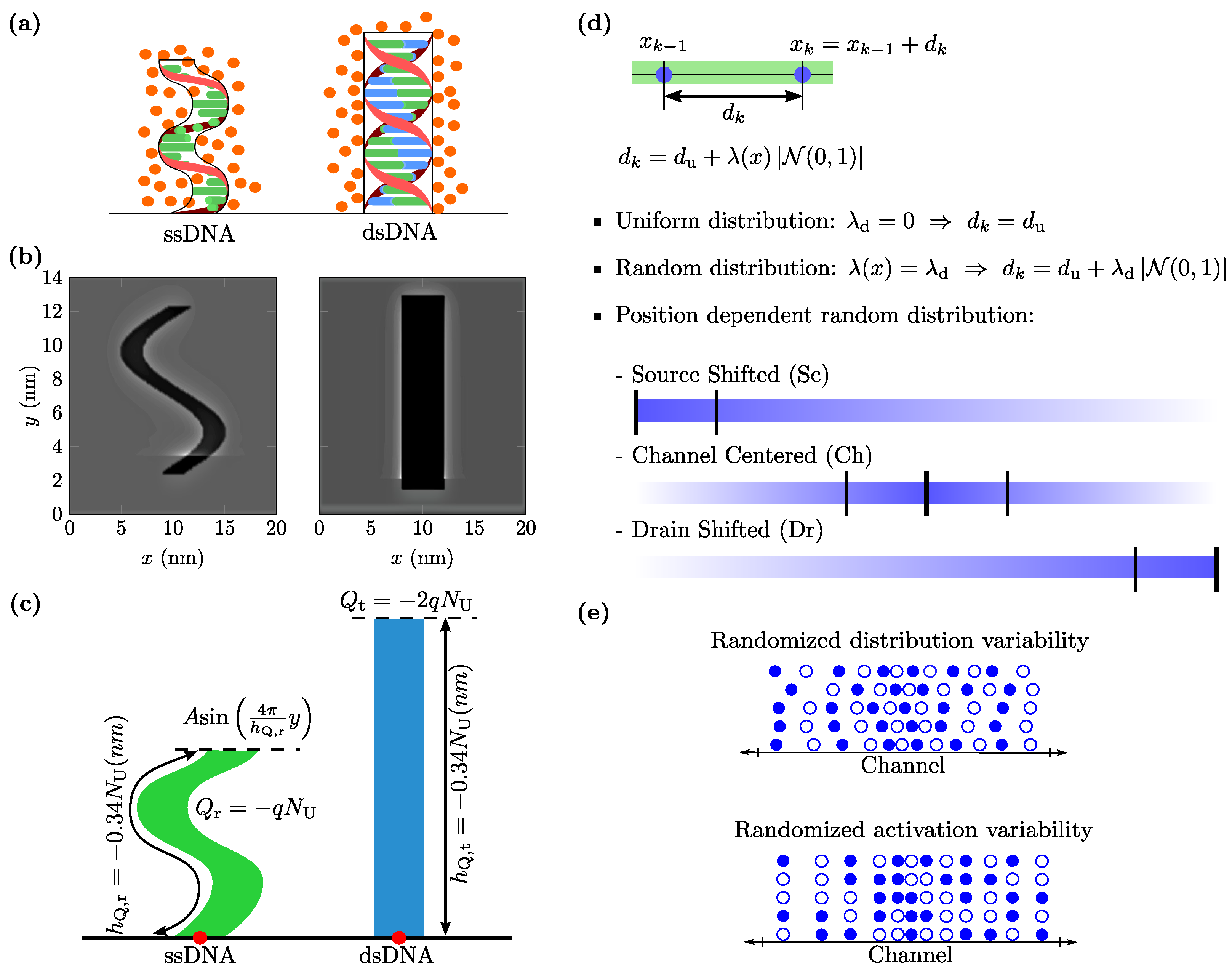
Figure 1. (a) Models for the ssDNA (receptor) and dsDNA (receptor-target complex) molecules. ssDNA model considers a sinusoid-shaped charged region where ions are allowed to enter, while the dsDNA model considers a box-shaped region where ions cannot penetrate. (b) Examples of simulated ion distributions regarding idle and activated DNA receptors. (c) Mathematical modeling of the length, shape and charge of ssDNA and dsDNA receptors. In both cases, the length of the molecule h Q and its charge Q is scaled with the number of nucleotides N U . (d) Location of receptors, controlled with the distance between them (for the k-th receptor, d k = x k x k 1 ). That distance is considered constant (uniform distribution) or defined by a half-normal distribution with a position dependent variance. This latter enables the definition of densely occupied regions at the sensing interface, allowing one to choose between the three distributions indicated by the blue bars. (e) Example of 5 channel-centered (Ch) distributions with P = 50 % , where filled and empty circles represent activated and deactivated receptors, respectively. Randomized distribution variability: considering a fixed activated receptor configuration (one occupied—one empty), several distributions are represented. Randomized activation variability: assuming a fixed receptor distribution, five activated receptor configurations are depicted.
Chemosensors 11 00057 g001
Figure 2. MoS 2 -based DNA BioFET outline. The dashed line determines the simulated area.
Chemosensors 11 00057 g002
Figure 3. (a) Current density I DS V FG shown in logarithmic scale. (b) Current density I DS V FG shown in linear scale. (c) Absolute current sensitivity S V FG . (d) Relative current sensitivity S r V FG . All results are calculated for different values of P with a uniform spatial distribution of receptors. Solid and dashed lines correspond to the 1   × PBS electrolyte and 0.1   × PBS electrolyte scenarios, respectively. The dotted line in (c) indicates the value V FG = 0.3 V for which S ( P = 100 % ) is maximum.
Chemosensors 11 00057 g003
Figure 4. (a) Device sensitivity as a function of the activation percentage. Ten random distributions following a channel centered case are considered, fixing the configuration of activated receptors for each P value. Markers account for simulated data, while shaded areas depict σ S and lines correspond to S . Both 1 × PBS (blue) and 0.1 × PBS (red) concentrations were simulated. Results obtained for the uniform distribution are depicted by dashed lines. (b) ζ ( P ) ratio. Markers represent simulated data, while colours refer to channel-centered, source-shifted and drain-shifted distributions. Both PBS concentrations are separated in two graphics for the sake of clarity. The dotted lines indicate ζ = 1 . Fitting parameters are summarized in Appendix A Table A1.
Chemosensors 11 00057 g004
Figure 5. (a) Device sensitivity as a function of the activation percentage calculated for twelve randomized activated receptors configurations corresponding to the same channel-centered distribution. Markers account for simulated data, while shaded areas depict σ S and lines correspond to S . Both 1 × PBS (blue) and 0.1 × PBS (red) concentrations were simulated. Results obtained for the uniform distribution are depicted by dashed lines. (b) ζ ( P ) ratio. Markers represent simulated data, while colours refer to channel-centered, source-shifted and drain-shifted distributions. Both PBS concentrations are separated in two graphics for the sake of clarity. The dotted lines indicate ζ = 1 . Fitting parameters are summarized in Appendix A Table A2.
Chemosensors 11 00057 g005
Disclaimer/Publisher’s Note: The statements, opinions and data contained in all publications are solely those of the individual author(s) and contributor(s) and not of MDPI and/or the editor(s). MDPI and/or the editor(s) disclaim responsibility for any injury to people or property resulting from any ideas, methods, instructions or products referred to in the content.