Article

ZnO and AZO Film Potentiometric pH Sensors Based on Flexible Printed Circuit Board

Graduate School of Electronic Engineering, National Yunlin University of Science and Technology, Douliou 64002, Taiwan
*
Author to whom correspondence should be addressed.
Chemosensors 2022, 10(8), 293; https://doi.org/10.3390/chemosensors10080293
Submission received: 27 June 2022 / Revised: 18 July 2022 / Accepted: 25 July 2022 / Published: 26 July 2022
(This article belongs to the Section Electrochemical Devices and Sensors)

Abstract

:
In this study, we deposited zinc oxide (ZnO) and aluminum-doped zinc oxide (AZO) on the electroless nickel immersion gold (ENIG) of a flexible printed circuit board (FPCB) as a potentiometric pH sensor. The sensing films of the pH sensor were fabricated by a radio frequency (RF) sputtering system and analyzed by field emission scanning electron microscope (FE-SEM) and X-ray photoelectron spectroscopy (XPS). In the pH 2 to 10 buffer solutions, it was observed that the characteristics of the pH sensor through the voltage–time (V-T) measurement system include average sensitivity and linearity, drift effect, and repeatability. According to the experimental results, the pH sensors in this study could exhibit good characteristics.

1. Introduction

pH sensors have been widely used in industrial, agricultural, medical, and other fields [1,2,3], so developing an accurate, durable, and low-cost pH sensor is crucial. Reviewing the literature on pH sensing or biosensor reveals that ZnO is a commonly used material [4,5,6,7]. It has the advantages of low cost, nontoxicity, wide bandgap (3.37 eV), remarkable exciton binding energy (60 meV), and room temperature stability [8]. Moreover, Khan, S. and Stamate, E. found that ZnO doping with group III elements can improve its electrical properties, especially electrical conductivity [9]. Therefore, it is worth noting that an interesting experiment can be conducted to better compare the pH sensing properties of AZO with a group III element and ZnO sensing films simultaneously. Since ZnO is an amphoteric oxide, it tends to have different chemical reactions in acid and alkaline solutions. In the preparation of sensing films, we prepared ZnO and AZO thin films using radio frequency (RF) sputtering. Through the adjustment of the working wattage, gas flow, deposition pressure, and deposition time, the RF sputtering method can produce uniform and dense thin films [10].
There are many types of sensing methods, such as cyclic voltammetry (CV) [11], differential pulse voltammetry (DPV) [12], and the amperometric method [13]. Compared with these methods, the potentiometric one is relatively noise-immune and can reduce damage to the sensing film, and the bias current is also negligible [14,15]. Furthermore, the potentiometric measurement technique has the advantage of simplicity due to relative insensitivity to the size of the sensing window, which implies its potential for miniaturization [15]. To better achieve potentiometric measurements, IA is often used to amplify the response voltage caused by the chemical reaction between the sensing film of the sensor and the solution used for testing [16]. We then observed the average sensitivity, linearity, time drift effects, and repeatability of the pH sensor based on this measurement system. Strong acid solutions can easily corrode ZnO or AZO films during pH measurement. It is a standard method to modify and protect the film with (3-aminopropyl)triethoxysilane (APTES) to prevent the film from dissolving [17]. In this study, we used APTES to modify the sensing film.
The substrate of the pH-sensing film is an essential part because it can be utilized to electrically connect the sensing window and the sensing circuit. Traditionally, glass [18], polyethylene terephthalate (PET) [19], and silicon [20] can be used as the substrate materials, which provide different application characteristics, such as acid and alkali resistance, heat resistance, and stability. At the same time, these traditional substrates can meet the basic requirements. However, in recent years, many researchers have proposed wearable sensors for proper application in biomedical areas or biosensors [21], so the sensors need to be flexible. In addition, the sensors need to be connected to the back-end readout circuit to measure the sensing data. To prevent errors in the measurement data, the robust electrical connection of the sensor is crucial. Flexible printed circuit boards (FPCBs) are commonly used in the industry because being an excellent sensing film substrate is characteristic of this type of circuit board. The required sensing film can be efficiently contrived through the mature printed circuit board (PCB) layout design process. This also makes the pH sensor easy to combine with the back-end readout circuit so that the entire sensing system can be integrated into the FPCB to better develop the wearable pH sensing system. In order to satisfy our performance on the new pH sensor to some extent, we propose a potentiometric pH sensor based on FPCB.
Immediately after the potentiometric pH sensors were ready, we utilized the voltage–time (V-T) measurement system to measure the sensing characteristics of the sensor. The readout circuit of the measurement system was mainly composed of instrumentation amplifiers (IAs). The IA’s high input impedance and common-mode rejection ratio (CMRR) can possibly prevent the loading effect and noise in the measurement process.

2. Materials and Methods

2.1. Materials

We used zinc oxide and aluminum-doped zinc oxide targets in the RF sputtering system to fabricate the sensing films of the pH sensor. The ZnO and AZO targets were purchased from Ultimate Materials Technology Co., Ltd. (Hsinchu City, Taiwan). The substrate of the pH sensor was FPCB, which was manufactured by Rui Xing Circuit Co., Ltd. (Foshan, China) based on the terms of the contract. The (3-aminopropyl)triethoxysilane (APTES), purchased from Sigma-Aldrich Co. (Louis City, MO, USA), was used as the protective layer of the pH sensor. The buffer solution measured in this experiment was formulated with citric acid powder, purchased from J. T. Baker Corp. (Radnor, PA, USA); boric acid powder, purchased from Katayama Chemical Co., Ltd. (Osaka City, Japan); sodium phosphate tribasic dodecahydrate powder, purchased from Four Plus Chemical Co., Ltd. (Kyoto City, Japan); and deionized (D.I.) water.

2.2. Preparation of the Buffer Solution

The buffer solution was mainly composed of citric acid powder, boric acid powder, trisodium phosphate dodecahydrate powder, and D.I. water. We prepared solutions “A” and “B”. The former has 0.05 M citric acid and 0.2 M boric acid. The latter has 0.1 M trisodium phosphate dodecahydrate. Based on the ratios of solution A and solution B shown in Table 1, we prepared buffer solutions at pH 2, pH 4, pH 6, pH 8, and pH 10 [22].

2.3. Preparation of the Zinc Oxide and Aluminum-Doped Zinc Oxide Films

We fabricated ZnO and AZO thin films through the RF sputtering system. To that end, ZnO and aluminum-doped ZnO targets were used, respectively. Furthermore, thin films were deposited on the six electrodes of the pH sensor as the primary sensing layer because films of different materials have their own optimal process parameters. For this reason, the experiment was conducted with the process parameters of the RF sputtering system to produce high-quality sensing films. The parameters include argon-to-oxygen ratio, deposition time, deposition pressure, and operating power [23]. Table 2 lists the sputtering parameters of these two sensing films.

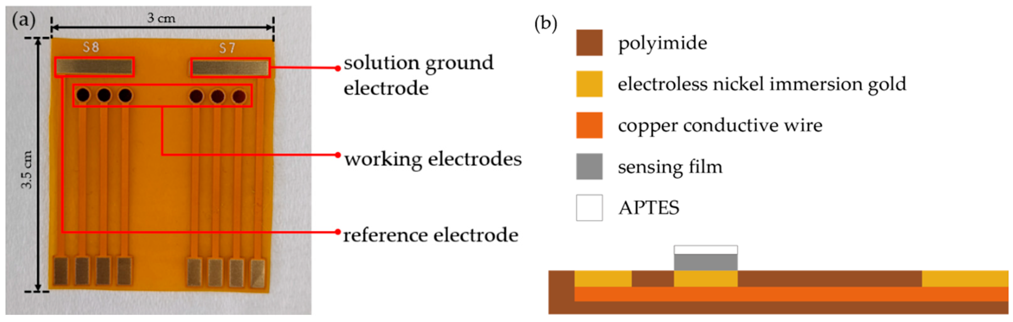
2.4. Preparation of the pH Sensors

Figure 1a illustrates the top view of the pH sensor. The substrate of the pH sensor was FPCB, with a size of 3 cm × 3.5 cm. The sensor was mainly composed of a solution ground electrode, a reference electrode, and six working electrodes. The area of each working electrode is 3.14 mm2, and the area of the solution ground electrode and reference electrode are both 22 mm2. Figure 1b depicts the side view of the pH sensor, showing the substrate of FPCB as polyimide, which has the advantages of flexibility, durability, and heat resistance [24]. Copper foil was used as the conductive material of FPCB. Because copper foil is easy to oxidize, we applied electroless nickel immersion gold (ENIG) surface finish technology to deal with FPCB. The ENIG has the characteristics of oxidation resistance, excellent conductivity, corrosion resistance, etc. [25]. These characteristics can increase the stability of the pH sensor, so the ENIG was used as the material of the solution ground electrode and reference electrode in this study. The preparation process of each pH sensor were as follows: First, we used acetone, alcohol, and deionized water to clean the FPCB with an ultrasonic cleaner, and then dried it with an air gun. Subsequently, the sensing films were prepared on the working electrodes of the pH sensor through the target and RF sputtering system. Finally, the pH sensor was prepared by dropping 2 μL of APTES diluted to 1% on the sensing films twice, which was then left to dry at room temperature.

2.5. Potentiometric Measurement System

In this study, the characteristics of the pH sensor were measured by the voltage–time (V-T) measurement system; the composition of the V-T measurement system is shown in Figure 2. Clearly, this system mainly includes (a) a computer with LabVIEW software, (b) the buffer solution and pH sensor, (c) a data acquisition device (DAQ), and (d) a readout circuit board. The operation flow of the V-T measurement system can be described as follows. First, we immersed the pH sensor in buffer solution. The sensing film of the pH sensor generated a response voltage due to a chemical reaction. Then, the response voltage signal is output to the DAQ through the readout circuit. The DAQ can convert analog signals to continuous digital signals. Finally, we analyzed the voltage and time of the measurement signal by the LabVIEW software.
The readout circuit board of the measurement system was composed of six instrumentation amplifiers (IA), and the model of the IA was LT1167. Very low DC offset, low drift, high input impedance, and very large CMRR are characteristics of IA [26]. Based on the above characteristics, we naturally opted for IA to be used for the pH sensor or biosensor measurement readout circuit. In order to actually observe the sensing characteristics of the pH sensor, we did not connect the gain resistor (Rg) of the IA to the readout circuit, so the voltage gain of the IA was 1. During the experiment, we connected the working electrode and the reference of the pH sensor to the positive and negative input terminal of IA, respectively. After this, the output of the IA was connected to DAQ, and the solution ground electrode was grounded so as to better provide a path for IA input bias current conduction to the ground. Based on the above circuit connection, the output voltage was the voltage difference between the voltage of the working electrode and the reference electrode.

3. Results and Discussion

3.1. pH Sensing Mechanism

There are several types of sensing materials used in pH sensors. In this work, zinc oxide and aluminum-doped zinc oxide films were employed as the pH sensor’s main sensing layer. When the working electrodes of the pH sensor were immersed in pH buffer solution, hydroxide was formed on the surface of the sensing film. This is because the surface of the sensing film was hydrolyzed by water, and so the surface of the sensing film was rich in hydroxyl groups by adsorption of ions or molecules [27]. When the sensing film underwent the chemical reaction with pH buffer solution, the binding sites on the film surface were protonated or deprotonated, causing the sensor to generate different response voltages in solutions with different pH values. This was because ZnO is an amphoteric oxide, and so the material has different chemical reactions in acidic and basic solutions. The chemical reactions of ZnO and AZO in acidic and basic solutions are represented by reactions (1) and (2) [27], respectively, and the electrochemical potential of the ZnO and AZO electrodes at room temperature can be represented by Formulas (3) and (4) [27].
In an acidic solution:
ZnOH 2 ( s ) + H ( aq ) + = ZnOH ( aq ) + + H 2 O
In a basic solution:
ZnO 2 H ( aq ) + + H ( aq ) + = Zn ( OH ) 2 ( s )
E = E O + 0.059 n log ( [ ZnOH + ] [ Zn ( OH ) 2 ] · [ H + ] ) E ref
E = E O + 0.059 n log ( [ ZnOH + ] [ Zn ( OH ) 2 ] ) + 0.059 n pH E ref
Formula (3) is the Nernst equation, where E refers to the response voltage of the pH sensor; E0 refers to the standard electrode potential of the metal oxide redox electrode, ZnOH+, Zn (OH)2, and H+ represents their activity; and Eref refers to the supplied potential of the standard reference electrode. With log ( 1 H + ) = pH , the potential of the ZnO and AZO electrodes are expressed by Formula (4). Moreover, since we modified APTES on the sensing film, the surface of the sensing film contains NH2 groups [28]. When the sensor is immersed in an acidic solution, NH2 will be protonated to NH3+. The reaction formula of APTES during measurement is as follows [17]:
APTES in solution:
NH 2 + H + NH 3 +

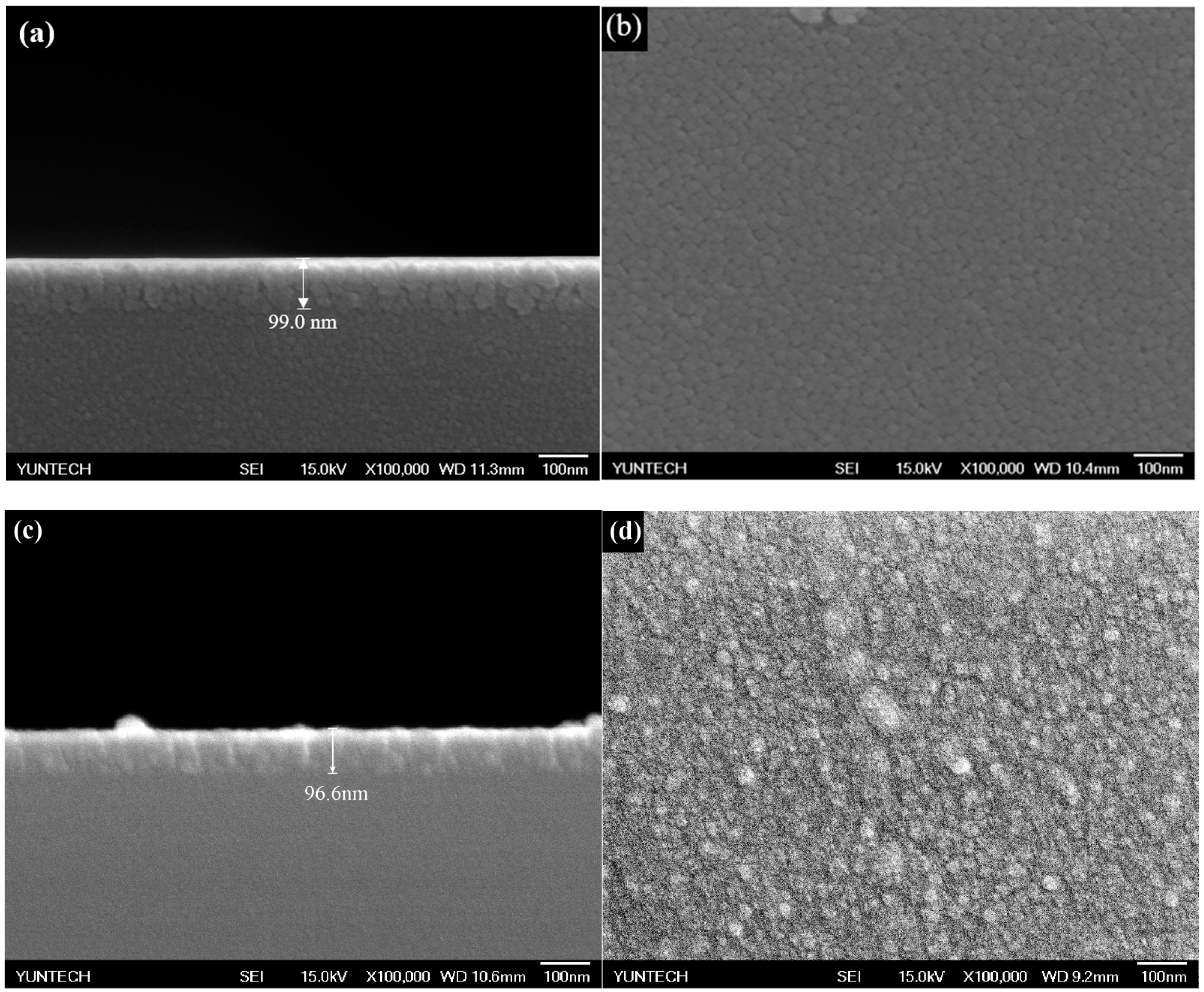
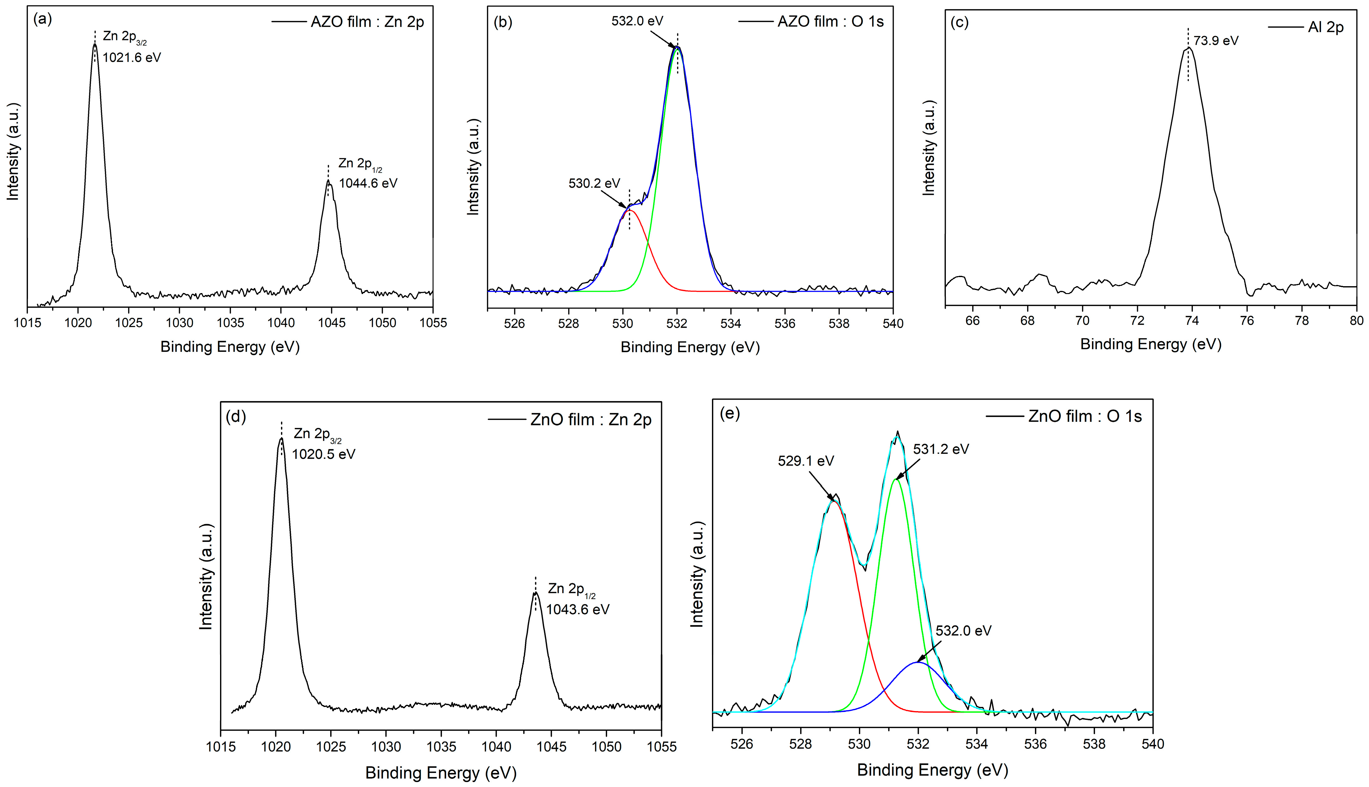
3.2. Analysis of the Zinc Oxide and Aluminum-Doped Zinc Oxide Films

A field emission scanning electron microscope (FE-SEM) was utilized to analyze the sensing films’ thickness and surface morphology. The instrument model of FE-SEM used was JSM-6701F, manufactured in Japan. Figure 3 presents the analysis results obtained with FE-SEM. According to the FE-SEM cross-section images of the sensing films, the thickness of the films was obtained. The thicknesses of ZnO and AZO films were 99.0 nm and 96.6 nm, respectively. As can be seen clearly from the FE-SEM top view of the sensing films, the sensing films prepared in this experiment are all made up of closely arranged particles, indicating that the sensing films of pH sensors are very uniform and dense.
X-ray photoelectron spectroscopy was adopted to analyze the composition and oxidation state of the sensing films; the instrument of XPS used was PHI 5000 VersaProbe III, manufactured in Japan. Figure 4 illustrates the analysis results by XPS. Figure 4a,d shows the Zn 2p high-resolution XPS spectrum of the AZO and ZnO films. The Zn 2p binding energy (BE) region of the AZO film has two strong peaks at 1021.6 eV and 1044.6 eV, while the Zn 2p BE region of the ZnO film has two strong peaks at 1020.5 eV and 1043.6 eV; these two peaks represent the BE at Zn 2p3/2 and Zn 2p1/2, and the peak at Zn 2p3/2 represents metallic zinc in stoichiometric ZnO. The peak at Zn 2p1/2 is related to Zn2+ ions in the hypoxic region, and the BE difference between the peaks at Zn 2p3/2 and Zn 2p1/2 is about 23 eV. Given these figures, the Zn atoms are in an +2 oxidation state [29]. Moreover, as can be seen clearly from (c), the Al 2p BE region of the AZO film has a strong peak at 73.9 eV. This is higher than that of metal Al (72.6 eV) and yet lower than that of Al2O3 (74.9 eV). Accordingly, most of the Al in the film tends to form Al-O-related chemical bonds in the ZnO matrix [30]. Figure 4b,e depicts the respective O 1s BE region of the AZO and ZnO thin films. The peak at 530.2 eV represents the O atoms surrounded by Zn2+ cations or Al3+ cations [31]. The higher peak (532.0 eV) can be related to the oxygen species adsorbed on the surface of the AZO film. The O 1s BE region shown in (e) was fitted by three single peaks, and O2 in the ZnO structure is related to the first peak (529.1 eV). The peaks at 531.2 eV and 532.0 eV can be attributed to the oxygen in the ZnO lattice with oxygen vacancy and the OH groups attached to zinc ions, respectively [32]. Based on the XPS measurement results, we can determine that the AZO film is composed of 43% zinc, 50% oxygen, and 7% aluminum, and the ZnO film is composed of 50% zinc and 50% oxygen.

3.3. The Average Sensitivity and Linearity of the pH Sensors

Since the response voltage we observed was the voltage difference between the working electrode (sensing film) and the reference electrode (ENIG), we had to ensure the chemical stability of the ENIG before measuring the sensing characteristics of the sensor. We subsequently immersed the ENIG in pH 2 to 10 buffer solutions and measured its surface potential. The measurement results are shown in Table 3. Based on the measurement results, we calculated the standard deviation, which was 3.17. This means that when the ENIG was immersed in different pH solutions, the change rate of the response voltage was about 3.17 mV, and the change rate of the response voltage generated by the sensing film in this study in solutions with different pH values was about 50 mV to 80 mV. Compared to the sensing film, the change rate of the ENIG was very low. Thus, the response voltage of the ENIG during measurement can be considered negligible.
In this study, two different materials were used to design the sensors; their architectures were mainly composed of ZnO/ENIG/Cu/PI and AZO/ENIG/Cu/PI. We set up the V-T measurement system to measure the average sensitivity and linearity of the pH sensor. By observing the average sensitivity of the sensor, we obtained the average value of the change of the response voltage of the sensor in different pH value solutions, and the linearity represents the sensor’s accuracy in measuring different pH concentrations. We sequentially immersed the pH sensors in buffer solutions of pH 10 to 2 at room temperature, then observed the change in their response voltage. Figure 5 illustrates the measurement results of the average sensitivity of the pH sensors based on bare ZnO film and bare AZO film, which were 19.52 mV/pH and 30.31 mV/pH, respectively. From the measurement results, it can be found that when the sensor was immersed in the pH 2 buffer solution, the change of response voltage was large and it was not linear with respect to the response voltages produced by the buffer solutions with other hydrogen ions’ concentrations because the films were corroded by the strong chemical reaction. Based on this reason, we modified APTES on sensing films to better increase the detection ranges of the pH sensors. Figure 6 illustrates the average sensitivity and linearity of the sensors after APTES modification; the average sensitivity and linearity of the modified-APTES ZnO film and AZO film were 26.70 mV/pH, 0.998 and 42.99 mV/pH, 0.996, respectively. According to the measurement results, we can prove that the modification of APTES on the pH sensor can prevent the sensing film from being corroded by a strong acid solution, and the sensitivity of the sensor will also be improved due to the protonation of NH2 groups on the sensing film. It is worth noting that the sensing properties of pH sensors based on AZO thin film were better than ZnO thin film because aluminum oxide has excellent mechanical, optical, and electrical properties and good chemical stability [33]. In Table 4, we compared the average sensitivity and linearity of the pH sensor in this study with several other pH sensors documented previously in the literature. Based on the comparison results, the average sensitivity of our pH sensors was better or at least equal to that obtained with other sensors, and the pH sensors in this study all had good linearity above 0.99.

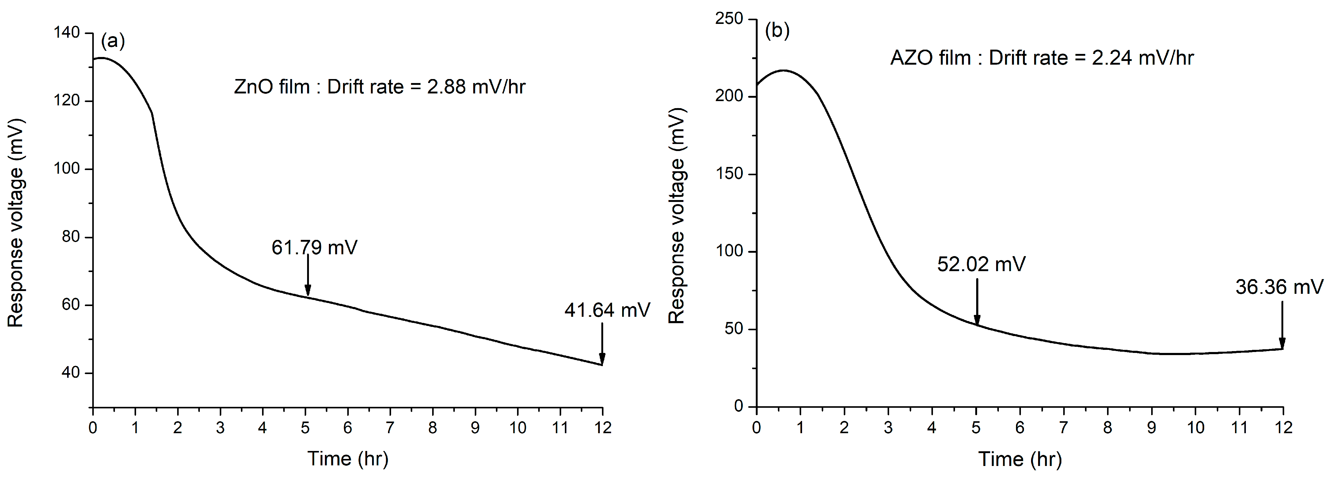
3.4. The Drift Effects of the pH Sensors

In terms of long-term measurement, we observed the drift effect in the pH sensors. We immersed the pH sensors in pH 7 buffer solution for 12 h and observed the response voltage of the pH sensors through the V-T measurement system. When the sensor was immersed in the testing solution for a long time, hydroxyl groups tended to form on the surface of the sensing film because the water in the solution has polar molecules, which tend to form hydrated ions through coulomb attraction with ions. Furthermore, a hydrated layer is likely to be formed when the hydrated ions diffuse to the sensing film. The surface potential of the sensing film changes due to the electrical double layer capacitance formed by the hydration layer [38]. The drift rate of the pH sensor can be calculated by Formula (6) expressed below [38].
Drift   rate = Drift   Voltage Time = V 12 V 5 7   h
where V5 is the response potential of the sensor stabilized after 5 h, V12 is the response potential of the sensor at 12 h, and the drift rate is defined as the potential difference between the 12th hour and the 5th hour divided by the measured time interval (7 h). The drift rates of the pH sensors based on ZnO and AZO films were 2.88 mV/h and 2.24 mV/h, respectively. The drift effect experiment results are provided in Figure 7. The comparison of the drift effect of our pH sensors with other related literature is also provided in Table 5. Based on the results derived from the comparison of the related literature, the drift rates of our pH sensors are below or nearly equal to those derived from other proposed sensors.

3.5. The Repeatability of the pH Sensors

To better confirm the stability of the ZnO and AZO thin-film sensors, we performed experiments on the repeatability of the pH sensor, as illustrated in Figure 8. We immersed the prepared sensors in the pH 6 buffer solution, measured its response voltage, and repeated this step five times. By referring to the measurement results, the relative standard deviation (RSD) was calculated; the lower the RSD value, the better stability of the sensor. The formula for calculating RSD can be expressed by Formula (7).
RSD = S X × 100 %
X refers to the average value of the response voltage measured times, and S refers to the standard deviation of measured times. The RSD values of pH sensors based on ZnO and AZO films were 2.3% and 3.1%, respectively. According to the experiment results, the RSD values of pH sensors in this study were below 5%, thereby proving that the sensors still have good stability under repeated use. In addition, these results can indirectly prove the durability of the FPCB [40].

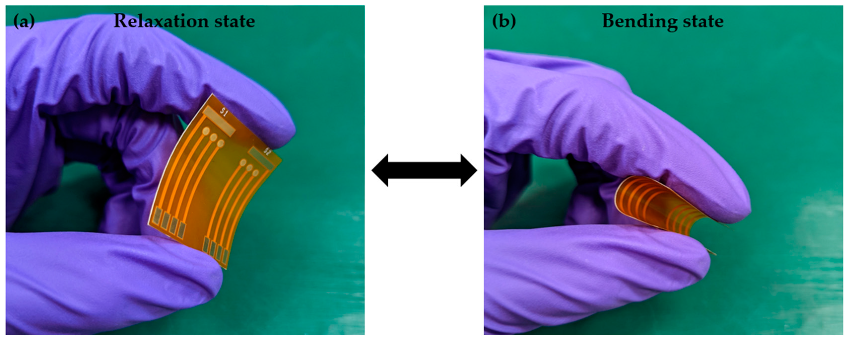
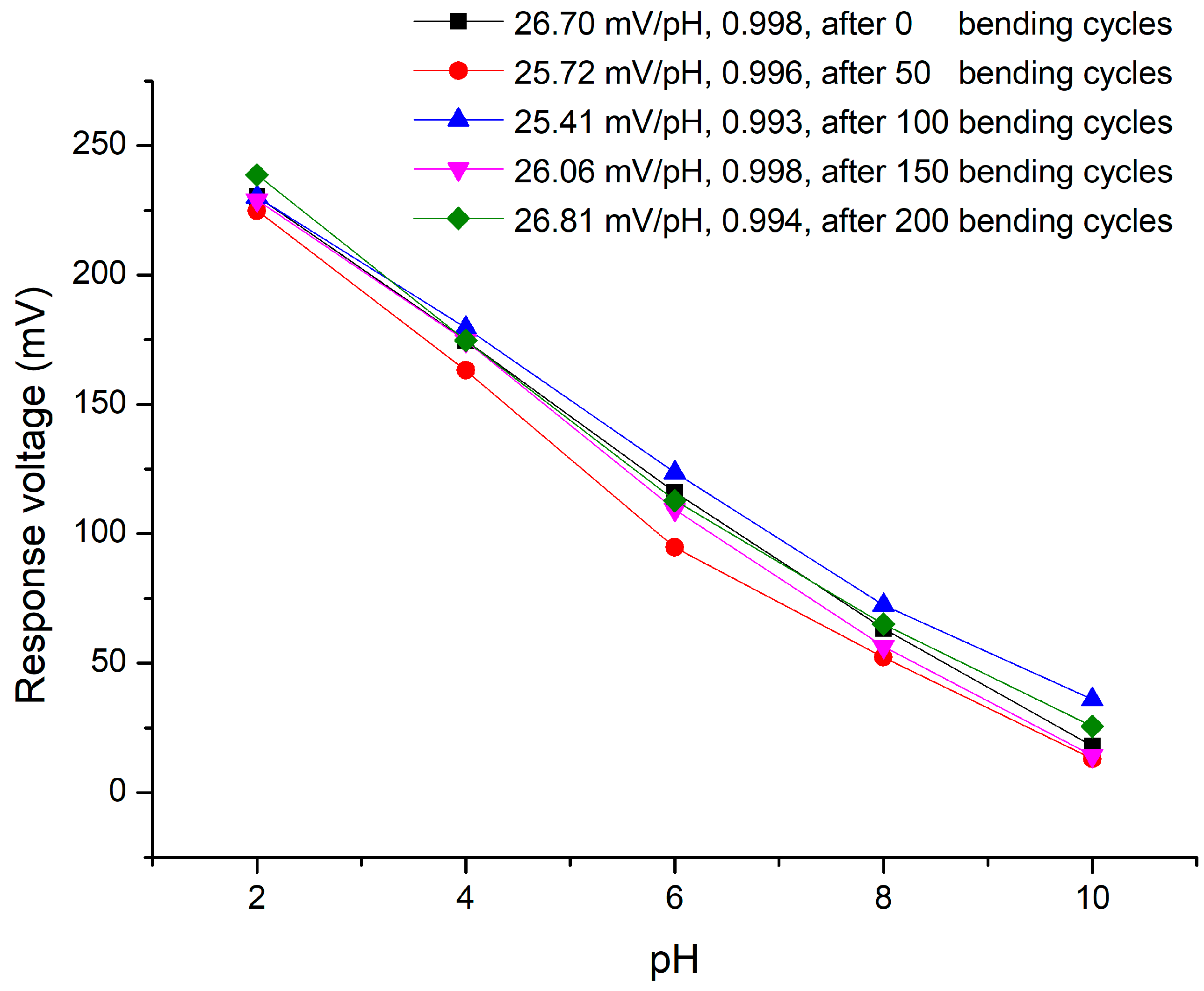
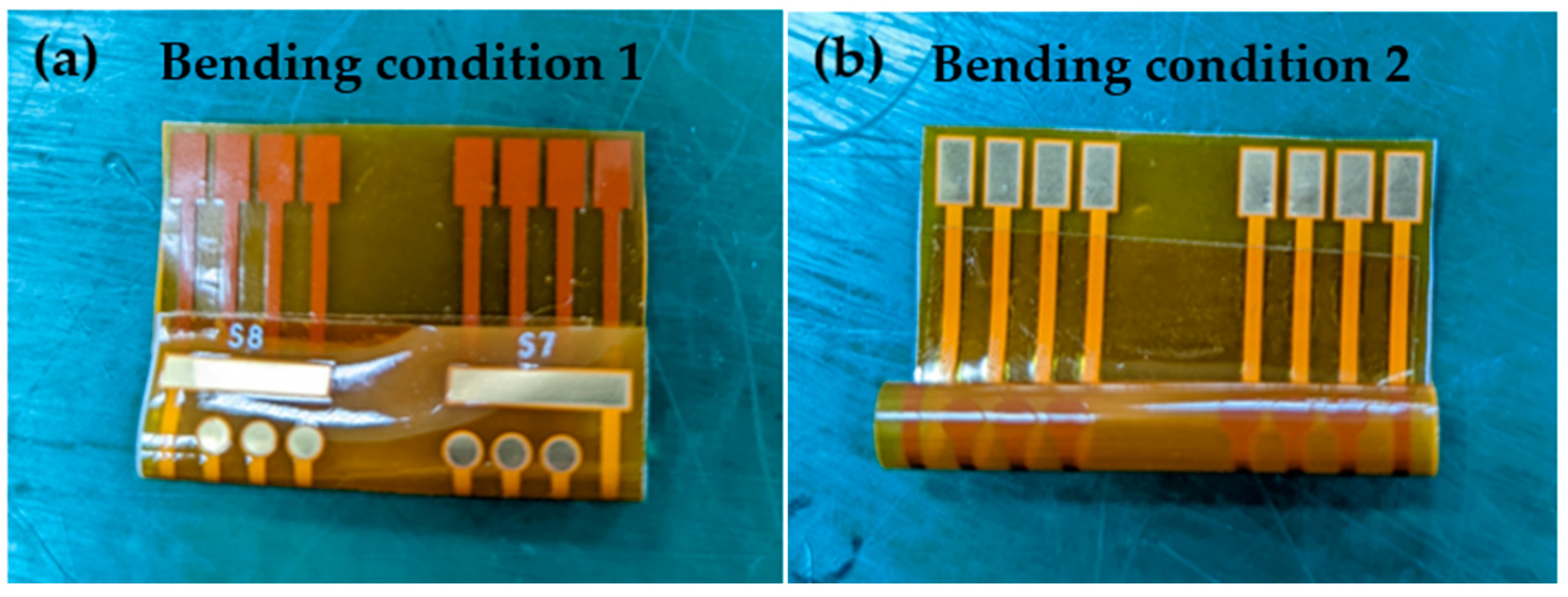
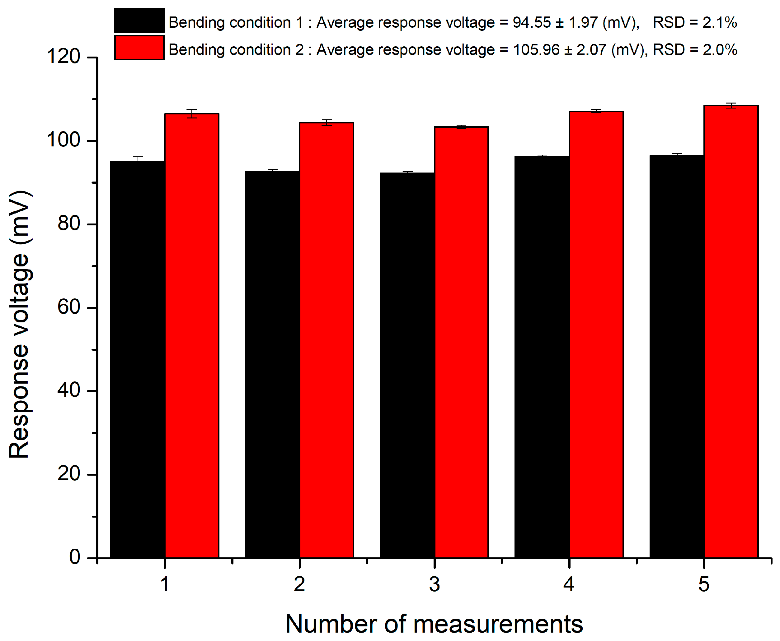
3.6. The Flexibility of the pH Sensors

To demonstrate the flexibility of the pH sensor based on FPCB, we confirmed the durability of the sensor through fatigue testing, and the stability of the sensor was proven by measuring the repeatability of the sensor upon the different bending conditions. The sensor structure of the above test is APTES/ZnO/ENIG/Cu/PI. In the fatigue experiment, we bent the sensor over 90 degrees from the center of the sensor, with a bending radius of 2 cm, as shown in Figure 9a. Immediately after this, it was released to the original state, as depicted in Figure 9b. The sensing characteristics of the pH sensor were measured after several bending cycles. In this experiment, the average sensitivity and linearity of the sensor after 0, 50, 100, 150, and 200 bending cycles were measured. Figure 10 shows the results of the sensitivity and linearity measurement after a few bending cycles. It is worth noting that the number of sensor bends does not affect the sensing performance. The average sensitivity was about 26.14 ± 0.61 mV/pH, and the linearity was higher than 0.99. This fatigue test not only proves the superior flexibility of the FPCB, but also confirms the stability of the pH sensor manufacturing process.
Regarding the repeatability experiment upon bending condition, we set the sensors to two different bending conditions, presented in Figure 11. In bending condition 1 (a), we bent the sensing window of the sensor 180 degrees backward with a bending radius of 1 cm; in bending condition 2 (b), we bent the sensing window forward 360 degrees with a bending radius of 0.5 cm. After bending, all the sensors were fixed with double-sided tape and then immersed in pH 6 buffer solution to measure the response voltage. After five measurements, we calculated the RSD value by using Formula (7). The experiment results are shown in Figure 12. According to the results, it can be determined that the sensor still has good stability when it is repeatedly used under different bending conditions. Based on this experiment, the flexibility of the pH sensor in this study was proven.

4. Conclusions

We successfully fabricated ZnO and AZO sensing films on the ENIG of an FPCB through the RF sputtering system and examined their sensing performance through the V-T measurement system. The surface morphology of the film was obtained with FE-SEM. This part of the result confirmed that the films prepared by this method were very uniform and dense. Also, the analysis of XPS further verified the composition and oxidation state. The experimental results indicate that the average sensitivities of our pH sensors based on ZnO and AZO films were 26.70 mV/pH and 42.99 mV/pH, respectively, thereby showing that doping aluminum to zinc oxide can increase the sensitivity of the sensor. Furthermore, the linearity of the pH sensors in this study was higher than 0.99, which means that our sensors have good accuracy. In addition, based on the results derived from the repeatability experiments, the RSD values of our pH sensors were all below 5%. This proves that the pH sensors based on FPCB are quite stable and durable. Ultimately, the fatigue test demonstrated the flexibility of the pH sensors. Moreover, the substrates of FPCB are maturing and sophisticated production technologies. Through the typical PCB layout software, different shape specifications can be created; thus, future pH-sensing films of FPCB substrates could have great potential to be miniaturized and used as portable devices.

Author Contributions

Conceptualization, resources, methodology, and supervision, P.-H.Y.; validation, investigation, and writing—review and editing, Y.-S.C.; data curation, formal analysis, and data curation, C.-T.C. All authors have read and agreed to the published version of the manuscript.

Funding

This research was funded by the Ministry of Science and Technology, Taiwan, Republic of China, under MOST 111-2221-E-224-058.

Institutional Review Board Statement

Not applicable.

Informed Consent Statement

Not applicable.

Data Availability Statement

Not applicable.

Conflicts of Interest

The authors declare no conflict of interest.

References

  1. Werner, J.; Belz, M.; Klein, K.-F.; Sun, T.; Grattan, K. Fiber optic sensor designs and luminescence-based methods for the detection of oxygen and pH measurement. Measurement 2021, 178, 109323. [Google Scholar] [CrossRef]
  2. Thakur, D.; Kumar, Y.; Kumar, A.; Singh, P.K. Applicability of wireless sensor networks in precision agriculture: A review. Wirel. Pers. Commun. 2019, 107, 471–512. [Google Scholar] [CrossRef]
  3. Cuartero, M.; Parrilla, M.; Crespo, G.A. Wearable potentiometric sensors for medical applications. Sensors 2019, 19, 363. [Google Scholar] [CrossRef] [Green Version]
  4. Das, S.C.; Pandey, R.R.; Devkota, T.; Chusuei, C.C. Raman spectroscopy as an assay to disentangle zinc oxide carbon nanotube composites for optimized uric acid detection. Chemosensors 2018, 6, 65. [Google Scholar] [CrossRef] [Green Version]
  5. Napi, M.L.M.; Sultan, S.M.; Ismail, R.; How, K.W.; Ahmad, M.K. Electrochemical-based biosensors on different zinc oxide nanostructures: A review. Materials 2019, 12, 2985. [Google Scholar] [CrossRef] [Green Version]
  6. Vinoth, V.; Subramaniyam, G.; Anandan, S.; Valdés, H.; Manidurai, P. Non-enzymatic glucose sensor and photocurrent performance of zinc oxide quantum dots supported multi-walled carbon nanotubes. Mater. Sci. Eng. B 2021, 265, 115036. [Google Scholar] [CrossRef]
  7. Palit, S.; Singh, K.; Lou, B.-S.; Her, J.-L.; Pang, S.-T.; Pan, T.-M. Ultrasensitive dopamine detection of indium-zinc oxide on PET flexible based extended-gate field-effect transistor. Sens. Actuators B Chem. 2020, 310, 127850. [Google Scholar] [CrossRef]
  8. Wang, Z.L. Zinc oxide nanostructures: Growth, properties and applications. J. Phys. Condens. Matter 2004, 16, R829–R858. [Google Scholar] [CrossRef]
  9. Khan, S.; Stamate, E. Comparative study of aluminum-doped zinc oxide, gallium-doped zinc oxide and indium-doped tin oxide thin films deposited by radio frequency magnetron sputtering. Nanomaterials 2022, 12, 1539. [Google Scholar] [CrossRef]
  10. Ekem, N.; Korkmaz, S.; Pat, S.; Balbag, M.; Cetin, E.; Ozmumcu, M. Some physical properties of ZnO thin films prepared by RF sputtering technique. Int. J. Hydrog. Energy 2009, 34, 5218–5222. [Google Scholar] [CrossRef]
  11. Mazzaracchio, V.; Fiore, L.; Nappi, S.; Marrocco, G.; Arduini, F. Medium-distance affordable, flexible and wireless epidermal sensor for pH monitoring in sweat. Talanta 2021, 222, 121502. [Google Scholar] [CrossRef]
  12. Sağlam, Ö.; Dilgin, D.G.; Ertek, B.; Dilgin, Y. Differential pulse voltammetric determination of eugenol at a pencil graphite electrode. Mater. Sci. Eng. C 2016, 60, 156–162. [Google Scholar] [CrossRef] [PubMed]
  13. Sha, R.; Komori, K.; Sushmee, B. Amperometric pH sensor based on graphene–polyaniline composite. IEEE Sens. J. 2017, 17, 16. [Google Scholar] [CrossRef]
  14. Jin, H.; Qin, Y.; Pan, S.; Alam, A.U.; Dong, S.; Ghosh, R.; Deen, M.J. Open-source low-cost wireless potentiometric instrument for pH determination experiments. J. Chem. Educ. 2018, 95, 326–330. [Google Scholar] [CrossRef] [Green Version]
  15. Walker, N.L.; Roshkolaeva, A.B.; Chapoval, A.I.; Dick, J.E. Recent advances in potentiometric biosensing. Curr. Opin. Electrochem. 2021, 28, 100735. [Google Scholar] [CrossRef]
  16. Kuo, P.-Y.; Chen, Y.-Y. A novel low unity-gain frequency and low power consumption instrumentation amplifier design for RuO2 uric acid biosensor measurement. IEEE Trans. Instrum. Meas. 2021, 70, 4003409. [Google Scholar] [CrossRef]
  17. Zhang, Q.; Liu, W.; Sun, C.; Zhang, H.; Pang, W.; Zhang, D.; Duan, X. On-chip surface modified nanostructured ZnO as functional pH sensors. Nanotechnology 2015, 26, 355202. [Google Scholar] [CrossRef]
  18. Qin, Y.; Alam, A.U.; Pan, S.; Howlader, M.M.; Ghosh, R.; Hu, N.-X.; Jin, H.; Dong, S.; Chen, C.-H.; Deen, M.J. Integrated water quality monitoring system with pH, free chlorine, and temperature sensors. Sens. Actuators B Chem. 2018, 255, 781–790. [Google Scholar] [CrossRef]
  19. Singh, K.; Lou, B.-S.; Her, J.-L.; Pang, S.-T.; Pan, T.-M. Super nernstian pH response and enzyme-free detection of glucose using sol-gel derived RuOx on PET flexible-based extended-gate field-effect transistor. Sens. Actuators B Chem. 2019, 298, 126837. [Google Scholar] [CrossRef]
  20. Pan, T.-M.; Lin, C.-H.; Pang, S.-T. Structural properties and sensing performance of TaOx/Ta stacked sensing films for extended-gate field-effect transistor pH sensors. J. Alloys Compd. 2022, 903, 163955. [Google Scholar] [CrossRef]
  21. Manjakkal, L.; Dervin, S.; Dahiya, R. Flexible potentiometric pH sensors for wearable systems. RSC Adv. 2020, 10, 8594–8617. [Google Scholar] [CrossRef] [PubMed] [Green Version]
  22. Carmody, W.R. Easily prepared wide range buffer series. J. Chem. Educ. 1961, 38, 559. [Google Scholar] [CrossRef]
  23. Pat, S.; Mohammadigharehbagh, R.; Özen, S.; Şenay, V.; Yudar, H.H.; Korkmaz, Ş. The Al doping effect on the surface, optical, electrical and nanomechanical properties of the ZnO and AZO thin films prepared by RF sputtering technique. Vacuum 2017, 141, 210–215. [Google Scholar] [CrossRef]
  24. Yang, C.; Xu, W.; Nan, Y.; Wang, Y.; Hu, Y.; Gao, C.; Chen, X. Fabrication and characterization of a high performance polyimide ultrafiltration membrane for dye removal. J. Colloid Interface Sci. 2020, 562, 589–597. [Google Scholar] [CrossRef]
  25. Kim, B.-K.; Lee, S.-J.; Kim, J.-Y.; Ji, K.-Y.; Yoon, Y.-J.; Kim, M.-Y.; Park, S.-H.; Yoo, J.-S. Origin of surface defects in PCB final finishes by the electroless nickel immersion gold process. J. Electron. Mater. 2008, 37, 527–534. [Google Scholar] [CrossRef]
  26. LT1167 Datasheet. Available online: https://www.analog.com/media/en/technical-documentation/data-sheets/1167fc.pdf (accessed on 26 June 2022).
  27. Al-Hilli, S.; Willander, M. The pH response and sensing mechanism of n-type ZnO/electrolyte interfaces. Sensors 2009, 9, 7445–7480. [Google Scholar] [CrossRef] [Green Version]
  28. Kumar, N.; Senapati, S.; Kumar, S.; Kumar, J.; Panda, S. Functionalized vertically aligned ZnO nanorods for application in electrolyte-insulator-semiconductor based pH sensors and label-free immuno-sensors. J. Phys. Conf. Ser. 2016, 704, 12013. [Google Scholar] [CrossRef]
  29. Das, J.; Pradhan, S.; Sahu, D.; Mishra, D.; Sarangi, S.; Nayak, B.; Verma, S.; Roul, B. Micro-Raman and XPS studies of pure ZnO ceramics. Phys. B Condens. Matter 2010, 405, 2492–2497. [Google Scholar] [CrossRef]
  30. Meng, F.; Ge, F.; Chen, Y.; Xu, G.; Huang, F. Local structural changes induced by ion bombardment in magnetron sputtered ZnO: Al films: Raman, XPS, and XAS study. Surf. Coat. Technol. 2019, 365, 2–9. [Google Scholar] [CrossRef]
  31. Challali, F.; Mendil, D.; Touam, T.; Chauveau, T.; Bockelée, V.; Sanchez, A.G.; Chelouche, A.; Besland, M.-P. Effect of RF sputtering power and vacuum annealing on the properties of AZO thin films prepared from ceramic target in confocal configuration. Mater. Sci. Semicond. Process. 2020, 118, 105217. [Google Scholar] [CrossRef]
  32. Nayak, P.K.; Wang, Z.; Anjum, D.H.; Hedhili, M.N.; Alshareef, H.N. Highly stable thin film transistors using multilayer channel structure. Appl. Phys. Lett. 2015, 106, 103505. [Google Scholar] [CrossRef] [Green Version]
  33. Sinha, S.; Pal, T.; Sharma, P.; Kharbanda, D.; Khanna, P.K.; Tanwar, A.; Sharma, R.; Mukhiya, R. Fabrication, characterization, and modeling of aluminum oxide-gate ion-sensitive field-effect transistor-based pH sensor. J. Electron. Mater. 2021, 50, 7085–7097. [Google Scholar] [CrossRef] [PubMed]
  34. Chiang, J.-L.; Tsai, S.-C.; Kao, M.-C. The pH sensitivity and characteristics of AZO nanorods based on the extended-gate field-effect transistor. J. Comput. Theor. Nanosci. 2015, 12, 825–831. [Google Scholar] [CrossRef]
  35. Tsai, Y.-T.; Chang, S.-J.; Ji, L.-W.; Hsiao, Y.-J.; Tang, I.-T. Fast detection and flexible microfluidic pH sensors based on Al-doped ZnO nanosheets with a novel morphology. ACS Omega 2019, 4, 19847–19855. [Google Scholar] [CrossRef] [Green Version]
  36. Young, S.-J.; Lai, L.-T.; Tang, W.-L. Improving the performance of pH sensors with one-dimensional ZnO nanostructures. IEEE Sens. J. 2019, 19, 10972–10976. [Google Scholar] [CrossRef]
  37. Young, S.-J.; Chu, Y.-J.; Chen, Y.-L. Enhancing pH sensors performance of ZnO nanorods with Au nanoparticles adsorption. IEEE Sens. J. 2021, 21, 13068–13073. [Google Scholar]
  38. Chou, J.-C.; Yan, S.-J.; Liao, Y.-H.; Lai, C.-H.; Chen, J.-S.; Chen, H.-Y.; Tseng, T.-W.; Wu, T.-Y. Characterization of flexible arrayed pH sensor based on nickel oxide films. IEEE Sens. J. 2017, 18, 605–612. [Google Scholar] [CrossRef]
  39. Kao, C.-H.; Liu, Y.-W.; Kuo, C.-C.; Chan, S.-M.; Wang, D.-Y.; Lin, Y.-H.; Lee, M.-L.; Chen, H. Comparison of ZnO, Al2O3, AlZnO, and Al2O3-doped ZnO sensing membrane applied in electrolyte-insulator-semiconductor structures. Membranes 2022, 12, 168. [Google Scholar] [CrossRef]
  40. Jafari, B.; Muthuvel, M.; Botte, G.G. Nickel-based electrochemical sensor with a wide detection range for measuring hydroxyl ions and pH sensing. J. Electroanal. Chem. 2021, 895, 115547. [Google Scholar] [CrossRef]
Figure 1. The (a) top view and (b) cross-section view of the pH sensor.
Chemosensors 10 00293 g001
Figure 2. The voltage–time (V-T) measurement system.
Chemosensors 10 00293 g002
Figure 3. The FE-SEM cross-section images of (a) ZnO and (c) AZO films, and the FE-SEM top view images of (b) ZnO and (d) AZO films.
Chemosensors 10 00293 g003
Figure 4. The XPS spectral analysis of sensing films includes (a) Zn 2p, (b) O 1s, and (c) Al 2p spectra of the AZO film and (d) Zn 2p and (e) O 1s spectra of the ZnO film.
Chemosensors 10 00293 g004
Figure 5. The average sensitivity and linearity of the pH sensors based on (a) bare ZnO film and (b) bare AZO film.
Chemosensors 10 00293 g005
Figure 6. The average sensitivity and linearity of the pH sensors based on (a) ZnO and (b) AZO films after APTES modification.
Chemosensors 10 00293 g006
Figure 7. The drift of the pH sensors based on (a) ZnO and (b) AZO films.
Chemosensors 10 00293 g007
Figure 8. The repeatability of the pH sensors based on ZnO and AZO films.
Chemosensors 10 00293 g008
Figure 9. Photograph of a fatigue test of the pH sensor based on FPCB.
Chemosensors 10 00293 g009
Figure 10. The average sensitivity and linearity of the pH sensor after 0, 50, 100, 150, and 200 bending cycles.
Chemosensors 10 00293 g010
Figure 11. The photographs of the sensors (a) after being bent 180 degrees backward with a bending radius of 1 cm and (b) after being bent 360 degrees forward with a bending radius of 0.5 cm.
Chemosensors 10 00293 g011
Figure 12. The repeatability of the sensors under two different bending conditions.
Chemosensors 10 00293 g012
Table 1. Preparation of the pH buffer solution.
pH ValueSolution “A” Volume (mL)Solution “B” Volume (mL)
248.751.25
438.7511.25
629.5020.50
821.2528.75
1013.5036.50
Table 2. The sputtering parameters of the sensing films.
FilmZnOAZO
Gas flow (Ar:O2)9:1 (sccm)9:1 (sccm)
Deposition time30 min50 min
Deposition pressure3 mTorr3 mTorr
Working power60 W60 W
Table 3. The potential of the ENIG in pH 2 to 10 buffer solutions.
pH Value246810
Response voltage (mV)7.172.121.518.396.94
Table 4. Comparisons of the average sensitivity and linearity based on pH sensors with different sensing materials.
Sensing LayerpH RangeSensitivity (mV/pH)LinearityRef.
ZnO film2−1019.52N/AThis study
AZO film2−1030.31N/AThis study
ZnO film
(after APTES modification)
2−1026.700.998This study
AZO film
(after APTES modification)
2−1042.990.996This study
AZO NRs7−1228.040.974[34] 2015
AZO NSs2−1249.62N/A[35] 2019
ZnO film4−1034.820.992[36] 2019
ZnO NRs4−1024.670.986[37] 2021
Table 5. The comparisons of the drift effect based on pH sensors with different structures.
Sensing LayerDrift Rate (mV/hr)Ref.
ZnO film2.88This study
AZO film2.24This study
ZnO film3.76[39] 2022
AZO film2.15[39] 2022
Publisher’s Note: MDPI stays neutral with regard to jurisdictional claims in published maps and institutional affiliations.

