Article

Effects of Calcination Temperature on CO-Sensing Mechanism for NiO-Based Gas Sensors

1
National Institute of Materials Physics, Atomistilor 405A, 077125 Magurele, Romania
2
Faculty of Physics, University of Bucharest, Atomistilor 405, 077125 Magurele, Romania
3
“Ilie Murgulescu” Institute of Physical Chemistry, Romanian Academy, Spl. Independentei 202, 060021 Bucharest, Romania
*
Author to whom correspondence should be addressed.
Chemosensors 2022, 10(5), 191; https://doi.org/10.3390/chemosensors10050191
Submission received: 13 April 2022 / Revised: 12 May 2022 / Accepted: 16 May 2022 / Published: 19 May 2022

Abstract

:
NiO-sensitive materials have been synthesized via the hydrothermal synthesis route and calcined in air at 400 °C and, alternatively, at 500 °C. Structural, morphological, and spectroscopic investigations were involved. As such, the XRD patterns showed a higher crystallinity degree for the NiO calcined at 500 °C. Such an aspect is in line with the XPS data indicating a lower surface hydroxylation relative to NiO calcined at 400 °C. An HRTEM microstructural investigation revealed that the two samples differ essentially at the morphological level, having different sizes of the crystalline nanoparticles, different density of the surface defects, and preferential faceting according to the main crystallographic planes. In order to identify their specific gas-sensing mechanism towards CO exposure under the in-field atmosphere, the simultaneous evaluation of the electrical resistance and contact potential difference was carried out. The results allowed the decoupling of the water physisorption from the chemisorption of the ambient oxygen species. Thus, the specific CO interaction mechanism induced by the calcination temperature of NiO has been highlighted.

1. Introduction

Carbon monoxide (CO) is a harmful gas to humans, and it is colorless, odorless, and insoluble in water [1]. CO is produced from the incomplete combustion processes of methane (CH4) and is prevalent in the waste gas emissions from industrial power plants [2]. On the other hand, this type of gas undergoes simple surface reactions, with most of the semiconducting metal oxides (MOX) being used for modeling of sensing and transduction phenomena [3].
Due to their moderate sensitivities towards different test gases, high chemical stability, and low fabrication costs, p-type MOX materials have been considered among the most promising materials for the further development of gas sensors [4,5]. Even though their gas-sensing mechanism is still controversial, there are plenty of reports revealing their peculiar gas-sensing performances [6,7,8]. Nickel oxide (NiO) has a wide band gap (Eg = 3.6–4.0 eV) and is a highly studied p-type MOX material for gas-sensing due to the small influence of humidity changes and good oxygen surface interaction [9]. Moreover, in NiO, the electrical transport properties are given by the Ni vacancies, leading to its p-type behavior [10]. As in the case of n-type MOX-based gas sensors [11,12] the changes in the electrical conductivity due to the surface adsorption/desorption of chemical species is the basic working mechanism. In the case of p-type NiO materials, the adsorbed surface oxygen ions remove electrons from the valence band, leading to the holes-accumulation layer near the surface. Upon surface interaction between reducing gases and oxygen species, electrons are released back to the valence band, reducing the hole concentration at the surface and thus increasing the electrical resistance of the material [13]. The catalytic and gas-sensing activities of the binary oxides are also highly influenced by morphological aspects, such as the size of the particles and the crystal grain faceting, not only with respect to the target gas but also to the atmospheric water, which may significantly influence the sensing mechanism. In terms of the function of the synthesis route, crystal grains with various shapes and sizes can be grown, showing preferential faceting according to {111}, {100}, {110}, or other higher Miller indices [14,15,16,17,18]. Studies referring to the dissociative adsorption of H2O onto NiO{111} and NiO{100} surfaces have evidenced a higher hydroxylation of the NiO{111} surfaces in comparison with NiO{100} surfaces [19,20,21].
Recently, different NiO nanostructures (nanoparticles, nanoplates, nanotubes, nanowires, or other complicated hierarchical microspheres) have been reported and their sensing properties were thoroughly investigated in order to boost their gas sensitivity [22]. Hussain et al. synthesized NiO microparticles via laser ablation, aiming to detect CO and CO2 gases. They showed that the sensitivity strongly depends on the laser fluences, but without taking into account the interfering role of humidity [23]. In the work of Drozdowska et al., they implemented a combination of electrical resistance and in situ FTIR spectroscopy techniques in order to depict the sensing mechanism towards NO2 in the presence of 40% RH. Additionally, they found that, by illumination with 275 nm, an accelerated and enhanced sensor response was achieved [24]. Kampara et al. studied the gas-sensing performances of PVA/NiO nanofibers synthesized via the electrospinning method towards formaldehyde when operated at 350 °C. Although the authors underline good responses and fast transients, ready for developing further devices for the diagnosis of pulmonary diseases, the effect of humidity was not considered [25]. Lekshmi et al. carried out gas-sensing investigations on NiO nanocrystals towards acetone gas. The obtained transients were: 26 s (response time) and 54 s (recovery time). The sensor signal towards 500 ppm of acetone reached the value of 128 without considering the role of moisture [26].
To the best of our knowledge, our previous work [27] was the only one addressing a sensing mechanism towards CO exposure under variable RH levels.
In this work, NiO nanomaterials were synthesized via the hydrothermal chemical route with an organic directing structural agent and were calcined at 400 °C and 500 °C. It is well known that the calcination temperature strongly influences the grain size and shape, as well as the surface-to-volume ratio, all of these with important consequences regarding the gas-sensing performance. The higher the calcination temperature is, the lower the specific surface area is due to the increase in the crystallite size. It is necessary to tune the surface area together with the crystallization degree via an optimized calcination temperature in order to boost the specific sensitivities of the investigated materials.
Accordingly, the paper aims to highlight the influence of the calcination temperature on the morphological properties that determine the specific CO-gas-sensing mechanisms.

2. Materials and Methods

2.1. Powder Synthesis and Layer Deposition

The NiO samples investigated in the present study were obtained following a synthesis protocol described in our previous report [27]. Briefly, the preparation method involves a hydrothermal synthesis route. In this procedure, we used Ni(NO3)2 hydrated as inorganic precursor dissolved in aqueous medium. Ethylene glycol (EG) and ethylenediaminetetraacetic acid (EDTA) were added as template and as a complexing agent. The hydrothermal treatment was performed at 180 °C for 24 h. The precipitate was filtered and washed with water and ethanol and dried and calcined in air at 400 °C and 500 °C for 8 h. The as-obtained powders calcined at 400 °C and 500 °C were mixed in a mortar with propanediol at specific ratio in order to obtain a homogenous paste and further transferred via screen printing onto commercial alumina substrates provided with platinum (Pt) electrodes on one side and Pt heater on the opposite side. The as-deposited sensitive materials were subject to drying process for 24 h at 60 °C temperature and, subsequently, by a gradual heating ramp in the oven up to 400 °C for 1 h. The firing profile ensures a good adherence of the sensitive materials to the substrates by a gradual removing of the organic binder (propanediol).
According to their initial calcination temperatures, the sensors have been labelled: NiO cal@400 °C and NiO cal@500 °C.

2.2. Materials Characterization

2.2.1. Structural Investigations

The X-ray diffraction (XRD) patterns were recorded with a Bruker D8 Advance X-ray diffractometer with a Cu anode and Ni filter (λ = 0.154184 nm) in Bragg–Brentano geometry. The XRD patterns were recorded in a wide 2θ range, up to 140°, for a high accuracy in the lattice parameters as obtained by Rietveld refinement (Topas v.3 software) of the experimental data [28].

2.2.2. Morphological Investigations

Investigations regarding the structure and morphology of the as-prepared NiO powders have been carried out with a JEOL JEM-2100 transmission electron microscope. The TEM samples have been prepared by powder crushing in a mortar, mixing with ethanol in order to disperse the nanoparticles, and dripping the obtained suspension on Cu grids provided with a lacey carbon membrane.

2.2.3. Surface Chemistry Investigations

In order to perform the surface chemistry investigations by using X-ray photoelectron spectroscopy (XPS), a PHI Quantera device was used. The pressure within the analysis chamber was set to 10−7 Pa. An Al Kα monochromatic X-ray source was used with the energy set to 1486.6 eV. In order to set up the internal calibration energy, the C1s reference was taken into account with the binding energy of 284.8 eV. It deserves to be noted that all the spectra were acquired for the “as received” NiO samples.

2.2.4. Gas-Sensing Investigations and Experimental Chronology

Sensing tests were carried out in a Teflon-coated chamber capable to measure basic electrical resistance changes (R) and contact potential differences (CPD) simultaneously. The experimental workbench for these characterizations allows us to perform in-field-like conditions measurements. Using certified gases from cylinders and further diluted with humified air via mass flow controllers (Bronkhorst, Ruurlo, Netherlands), we could deliver different CO concentrations over the NiO-based gas sensors with high accuracy within the error range of 1% of the calibration curve. The total gas flow through the system was kept constant at 200 sccm. The electrical changes of the sensors were collected by means of Keithley 6517A electrometer and the CPD changes via McAllister KP6500 Kelvin probe [29]. The bias voltage applied was set to 3 V for all investigated sensors throughout the complete measuring time-length. The sensors were heated by means of a power supply. The electrical socket of the heating and the measuring circuit are Teflon-coated in order to avoid any outgasing issues and guard from stray electric fields (Figure 1).
The Kelvin probe consists of a metallic tip being gas-inert and electrically isolated. A potential drop, the so-called contact potential: ∆VCPD = ∆Φ/q results between the NiO sensor and Kelvin probe tip. Thus, the relative work function (ΔΦ) of the investigated material can be calculated.

3. Results

3.1. XRD Results

Figure 2 shows the XRD patterns of the NiO samples indexed as cubic NiO, space group Fm-3 m (S.G. no. 225), ICDD-01-071-1179. Narrower diffraction peaks are observed for the NiO sample calcined at 500 °C in relation to the peaks of the sample calcined at 400 °C, associated with a higher crystallinity degree of the corresponding nanoparticles. The Rietveld analysis determined the average crystallite size d = 11 ± 2 nm for the NiO sample calcined at 400 °C, d = 19 ± 2 nm for the NiO sample calcined at 500 °C, and the same lattice parameter a = 0.4178 ± 0.0001 nm for both samples.

3.2. Analytical TEM Results

The morphological and structural characteristics of the samples calcined at 400 °C and 500 °C have been evaluated by TEM investigations. In both cases, the obtained crystalline phase is the same, namely the face-centered cubic structure of NiO. This is demonstrated by the SAED patterns inserted in Figure 3a,b, which have been indexed according to the 4329323 cif file (S.G. no. 225, a = 0.417861 nm). Noticeable differences can be observed, though, from the morphological point of view. The average particle size increases from ca. 9 nm in the case of the 400 °C sample (Figure 3a) to ca. 20 nm for the sample calcined at 500 °C (Figure 3b). While the calcination at 400 °C produces small particles with a quasi-spherical shape, at 500 °C, an increased number of nanoparticles show well-defined facets, generating polyhedral nano-objects. The quasi-spherical aspect of the NiO nanoparticles at 400 °C, as noticed at lower magnifications, is due to the limited 3D size of the NiO nanoparticles in the absence of a pronounced growth anisotropy and their truncation most likely according to the {111} family of planes, generating icosahedral and decahedral nano-objects. The higher calcination temperature determines the coalescence of the small particles and the growth of larger nanoparticles, with a better surface definition and a preferential faceting, most likely according to the {100} or {111} families of planes. A similar behavior of the nanocrystals’ shape in function of their size has been evidenced experimentally by T. Ling et al. for fcc Fe nanoparticles [30], demonstrated by Gibbs free energy calculations, indicating that surface energy minimization plays the most important role in determining the nanoparticles’ shape, in competition with the cohesive energy, the elastic strain energy, and the twin boundary energy.
At a higher magnification, the HRTEM micrographs show that both samples are fully crystallized, showing lattice fringes corresponding to the fcc NiO crystal structure. For the sample calcined at 400 °C, one can see that the size of the coherent crystalline domains is even lower than the nanoparticle size measured on the lower magnification micrographs and that the grain faceting is extremely limited. The quasi-spherical aspect observed at a lower magnification is replaced by a rather irregular aspect of the nanoparticles’ surface. A single well-defined crystal grain can be observed in the central part of Figure 4a. On the enlarged image in Figure 4b, one can notice the [001] crystallographic orientation of this grain and the faceting according to {100} planes. Nevertheless, most of the surrounding nanoparticles show a rather rough surface with a high density of surface defects, such as steps, corners, and kinks.
Apart from the noticeable size increase and faceting enhancement, the sample calcined at 500 °C is also characterized by the presence of crystallographic defects trapped inside the particles, most likely as a result of the coalescence process. These are either planar defects, like twin boundaries, or low angle grain boundaries, pointed by white arrows, as in Figure 4c. These defects define coherence domains of the order of 5–10 nm inside the nanoparticles. The average size of the coherence domain is of the same order of magnitude as the nanoparticle at 400 °C, which suggests a coalescence process during the calcinations at 500 °C. A typical example is presented by the HRTEM micrograph in Figure 4d, showing a rather large (>20 nm) nanoparticle close to the [01-1] orientation. Double white lines indicate the (111) and (200) lattice fringes spaced at 0.241 nm and 0.209 nm, respectively. Inside the nanoparticle, two parallel (−111) twin boundaries delimitate three coherent twin domains. The trace of the (100) planes zig-zag-ing across the twin boundaries is indicated by single white lines. The analyzed particle shows lateral facets according to the (100), (111), and (−111) planes, as observed from the orientation of the corresponding lattice fringes running parallel to the particle sides. It is rather difficult to say whether the upper and bottom bordering surfaces are rigorously planar. The fact that we observe a rather uniform contrast makes us conclude that there are no significant thickness variations, which means that the top and bottom bordering (01-1) surfaces (along the e-beam direction) are rather flat.
As a conclusion of the TEM microstructural investigation, we mention that the two samples differ essentially at the morphological level. While the sample calcined at 400 °C consists of small-sized crystalline nanoparticles, with less if any facetted grains, forming clusters where the nanoparticles are in contact with each other, the 500 °C sample shows noticeable larger nanoparticles, with an enhanced faceting according to the main {100}, {110}, or {111} crystallographic planes.

3.3. X-ray Photoelectron Spectroscopy (XPS) Results

In order to assign the Ni chemical species detected by XPS, we accomplished the deconvolution of the Ni2p3/2 high-resolution spectra based on the ISO-TC201 (‘‘Surface Chemical Analysis’’—SCA) recommendations and NIST X-ray Photoelectron Spectroscopy Database [31]. In addition, a critical review of the literature data was performed in order to ensure, as best as possible, the accuracy and reliability of the obtained results. The accuracy for the binding energies (BEs) assignments was ±0.2 eV. Figure 5a,b shows the deconvoluted Ni2p3/2 photoelectron spectra for the NiO samples thermally treated at 400 °C and 500 °C, respectively. A close inspection of the Ni surface chemistry reveals the presence of two different chemical species as follows: (i) the Ni detected at BE~853.5 eV is attributed to the Ni2+ bonded into the NiO structure with a lower crystallinity degree. The formation of the amorphous NiO cannot be completely ruled out [32,33]. (ii) The Ni detected at the BE~855.2 eV is ascribed to the NiO associated with a higher crystallinity degree, as was confirmed by XRD analysis and the literature reports [34,35,36,37]. Moreover, the HRTEM highlighted a better surface definition and a preferential faceting for the sample calcined at 500 °C. (iii) The peak fitted at BE ~ 857 eV accounts for the NiO multiplet splitting (MS). [38,39]. On the other hand, the broad and intense ‘‘shake-up’’ satellite peaks located at BE around 861.5 eV are the fingerprint for the NiO formation. In line with these findings, we conclude that the chemical species, such as Ni2O3 and Ni(OH)2, were not detected on the surface. These statements are clearly supported by the characteristic binding energies for the Nip3/2 and O1s spectra, which should be shifted toward higher binding energies as compared to our own data on NiO sensors [39,40,41].
The oxygen chemistry was assessed from the high-resolution (HR) O1s spectra following the spectral deconvolution procedure (Figure 5b,c). Thus, for both samples, three oxygen chemical species were highlighted as follows: (i) O2− at 529.5 eV attributed to the lattice oxygen, (ii) OH groups adsorbed on the surface assigned to the BE around 531 eV [31], and (iii) H2O at BE~533 eV [31]. Concerning the surface hydroxylation, one can notice that the thermal treatment at 400 °C leads to a surface with a larger percentage of OH-adsorbed groups. While the sensor labeled NiO cal@400 °C exhibits 42.9% lattice oxygen, 45.5% OHads, and 12.5% H2O, the NiO cal@500 °C shows a lower amount of OH groups (27.3%) and, roughly, the same amount of H2O (13.3%). We emphasize that, although, with increasing temperature, the OH groups are partially desorbed, the water content remains approximately constant, around 13%.

3.4. Gas-Sensing Results

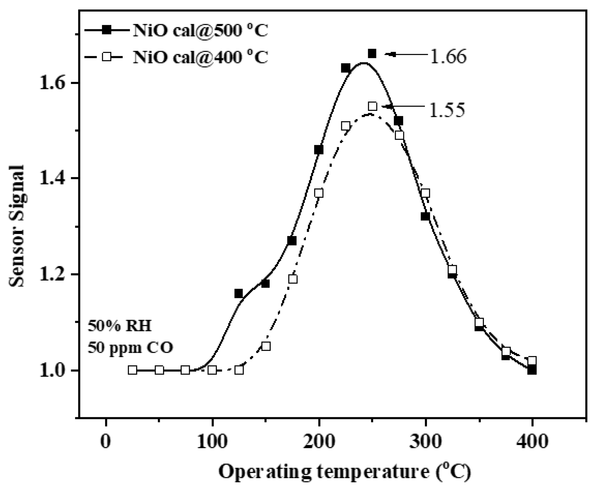
Usually, when p-type MOX is exposed to in-field atmosphere, oxygen and hydroxyl species are adsorbed, depending on the operating temperature and surface intrinsic properties [42]. The resulted hole accumulation region leads to an increase in the overall conductance of p-type material, in our case, NiO. In order to find the optimum operating temperature where CO detection takes place, the NiO cal@ 400 °C- and NiO cal@500 °C-based gas sensors were measured at different temperatures from 26 °C to 400 °C. As can be seen in Figure 6, the sensor signal (defined as S = RCO/Rair, where RCO is the electrical resistance under 50 ppm CO exposure and Rair is the electrical resistance under reference synthetic air with 50% RH) increases with the increase in operating temperature, reaching a maximum at 250 °C for both materials, followed by an abrupt decrease to 400 °C. Such behavior is commonly observed for most of the MOX-based gas sensors and can be explained by the balance between the speed of the adsorption/desorption and gas diffusion [43].
Making use of the classical theory of grain-to-grain boundary, we would have expected a decrease in the sensor signal [44] when the grain size increases from 9 nm to 20 nm, according to HRTEM investigations. On the contrary, an increase in the sensor signal with about 6% for NiO cal@500 °C was recorded, revealing specific surface behavior that cannot be explained solely based on the sensor signal. By simultaneous electrical resistance and contact potential difference measurements upon CO exposure in the presence of 50% RH, it becomes possible to decouple between ionosorption (surface band bending (∆VS) changes) and physisorption (electron affinity (∆χ) changes). The former controls the conduction changes upon gas exposure by a change in the potential barrier height, whereas the latter provides information about the surface reactivity. The condition of Debye length (LD) < grain radius (r) should be considered for both NiO cal@400 °C and NiO cal@500 °C since LD [45] is approximated to 1–2 nm (since the hole concentration equals 1.3 × 1019 cm−3) using the following relation (1):
L D = ε ε 0 k B T q 2 p b
where: ε is the NiO permittivity; ε0 is the permittivity of free space; kB is the Boltzmann constant; T is the operating temperature; q is the charge of an electron; and pb is the concentration of holes in the bulk.
Work function (∆Φ) is calculated as qCPD based on experimental data and contains three contributions: band bending qVS, electron affinity ∆χ, and the energy difference between the conduction band and Fermi level in the bulk (EC−EF)bulk:
Φ = q C P D = q V S + χ + ( E c E F ) b u l k
Considering the last term constant, the first two contributions may change upon gas exposure.
It is worth mentioning that the changes of each influence the work function but without changing each other.
Specific for p-type MOX, surface band bending is related to the electrical resistance, according with Equation (3):
q V S = 2 k B T l n ( R C O R a i r )
In order to avoid any interference between CPD and the resistance measurement, the investigations have been performed simultaneously and data analysis was completed using the same time scale.

3.4.1. Gas-Sensing Mechanism towards CO Exposure under 50% RH for NiO Calcined at 400 °C

Equations (2) and (3) were used to characterize the CO-sensing mechanism in the presence of 50% RH. Under these in-field conditions, potential reaction partners for CO are various oxygen ions, such as: O 2 ,   O ,   O 2 , and hydroxyl species OH . According to Refs. [46,47], mostly O   ions might be adsorbed on the surface of NiO nanomaterials.
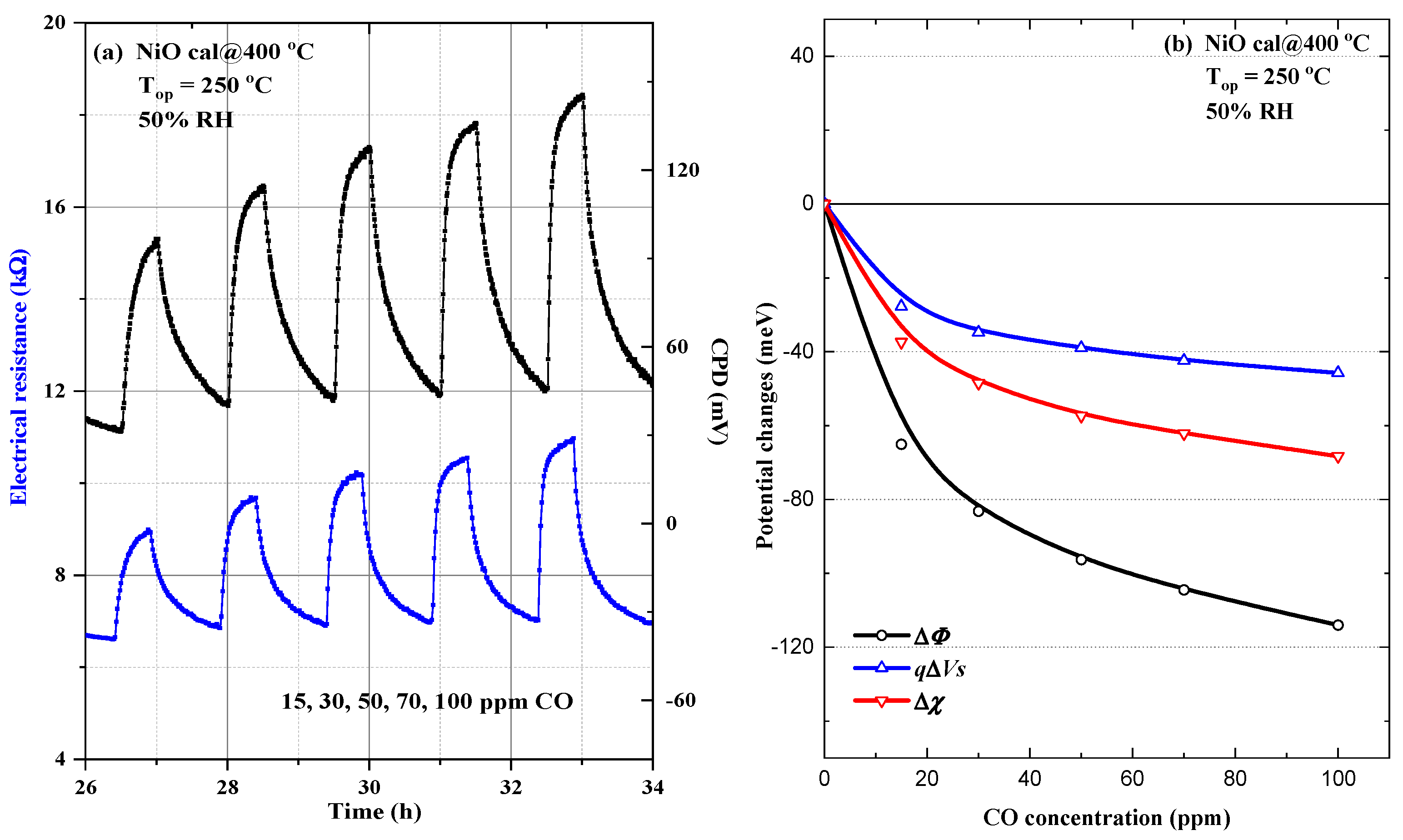
As can be seen in Figure 7a, with an increasing CO concentration, both the resistance and contact potential differences change monotonously as an effect of successive exposure to progressive CO concentrations, from 15 to 100 ppm. The measurement protocol alternates the CO exposure from 30 min with synthetic air with 50% RH exposure for 1 h.
In Figure 7b, it is observed that both surface band bending qVS and electron affinity ∆χ decrease as the CO concentration increases. It deserved to be noticed that the decrease in ∆Φ results as the sum of the two individual decreases (surface band bending and electron affinity)
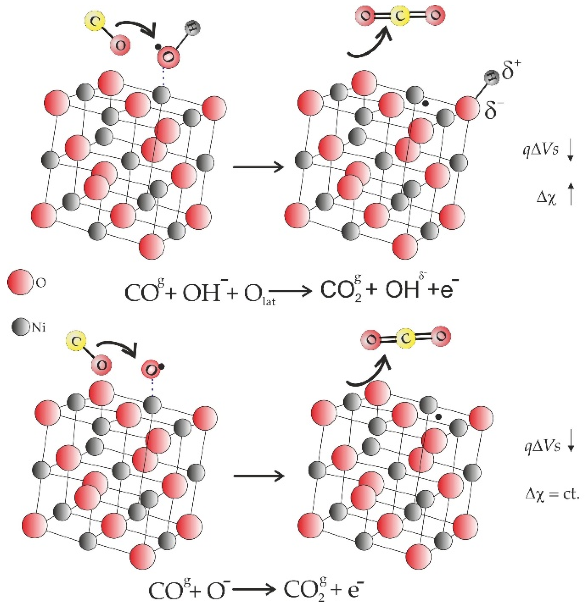
In order to explain such an effect, one has to consider the interaction between CO and weakly bonded hydroxyl groups on the NiO surface, releasing electrons in the valence band (decrease in the qVS) and decreasing the surface coverage with OH groups (∆χ decreases). Thus, an appropriate reaction mechanism is sketched in Figure 8.

3.4.2. Gas-Sensing Mechanism towards CO Exposure under 50% RH for NiO Calcined at 500 °C

Even if qualitative, electrical resistance, and CPD exhibit similar behaviors, there are quantitative differences between NiO calcined at 500 °C and NiO calcined at 400 °C when comparing Figure 7a and Figure 9a. Upon a closer look at the experimental results, we obtain, using Equations (2) and (3), similar dependencies for work function ∆Φ and surface band bending qVS but opposite for electron affinity variation ∆χ (Figure 9b). More specifically, ∆χ increases for the first CO concentration and further remains relatively constant.
The presence of two situations might be attributed to different interaction partners at the NiO surface. Accordingly, we propose a two-fold mechanism involved in CO detection with gas sensors based on NiO calcined at 500 °C.
The increase in the electron affinity can be explained following two models, suggested by Heiland and Kohl [48], envisaging water dissociation on the reactive surface heated at 250 °C. Accordingly, an interaction with the surface hydroxyl groups is likely to occur. On the other hand, the electron affinity remains relatively constant above 15 ppm CO, while the surface band bending decreases pronouncedly when compared to NiO cal@400 °C. Across the whole range of CO concentrations, the behaviors of ∆χ and qVS can be attributed to the interaction between CO and surface-adsorbed OH and also to the O   competitive adsorption, according to the chemical interactions sketched in Figure 10.
Based on these results, it is plausible to assume that the higher CO sensitivity for NiO calcined at 500 °C is related to two contributions within the sensitive layer, which behave qualitatively differently. These two potential contributions can be associated with the HRTEM investigations that underlined two different facets of the crystallites and also to the XPS results that highlight the differences related to the amount of lattice oxygen and OH groups as a premise for specific surface interactions.

4. Conclusions

In this work, we investigated the role played by the calcination temperature of NiO-based gas sensors regarding the CO-sensing mechanism under in-field conditions. According to the HRTEM investigations, an increase in the calcination temperature from 400 °C to 500 °C brings a faceting enhancement, as well as an increase in the particle size from 9 nm to 20 nm. Moreover, the XPS results emphasize the fact that, the lower the calcination temperature is, the higher the amount of surface hydroxyl groups is. We cannot quantitatively evaluate from the TEM observations what fraction of the total surface area is represented by {111} faceting in comparison with {100} faceting or other high Miller index local surface orientations. However, the presence of H2O and OH, evidenced by the deconvoluted XPS peaks for the O1s singlet and the role played by the OH in the sensing mechanisms, can be related to a significant fraction of the NiO nanoparticles exhibiting {111} faceting. As such, we developed an appropriate gas-sensing mechanism towards CO exposure with respect to the calcination temperature. By decoupling the potential changes (e.g., work function, surface band bending, and electron affinity), we underlined the following:
-
For NiO calcined at 400 °C, CO prefers a direct interaction with the surface hydroxyl groups;
-
For NiO calcined at 500 °C, a two-step reaction mechanism is possible above and below 15 ppm of CO, namely: with the surface hydroxyl groups (up to 15 ppm CO) followed by CO–oxygen interaction above 15 ppm CO.

Author Contributions

Conceptualization, A.S. and C.E.S.; materials preparation, S.S.; sensors fabrication and electrical investigations, O.G.F.; XRD investigations, D.G.; XPS investigations, S.S.; TEM investigations, C.G. and C.G.M.; writing—original draft preparation, C.E.S.; writing—review and editing, all authors. All authors have read and agreed to the published version of the manuscript.

Funding

This work was funded by a grant of Ministry of Research, Innovation and Digitization CNCS/CCDI-UEFISCDI through the project PN-III-P4-ID-PCE-2020-0506 (contract no. 116/2021) within PNCDI III and by Romanian National Authority for Scientific Research through the Core Program PN19-03 (contract no. 21 N/08.02.2019). The contribution of Catalina G. Mihalcea (C.G.M.) to this work is part of the PhD “Nanostructured materials for gas sensing: correlations between functional, electronic and microstructural properties” supported by CERIC-ERIC.

Conflicts of Interest

The authors declare no conflict of interest. The funders had no role in the design of the study; in the collection, analyses, or interpretation of data; in the writing of the manuscript, or in the decision to publish the results.

References

  1. Dey, S.; Mehta, N.S. Oxidation of carbon monoxide over various nickel oxide catalysts in different conditions: A review. Chem. Eng. J. Adv. 2020, 1, 100008. [Google Scholar] [CrossRef]
  2. Khodmanee, S.; Amnuaylojaroen, T. Impact of Biomass Burning on Ozone, Carbon Monoxide, and Nitrogen Dioxide in Northern Thailand. Front. Environ. Sci. 2021, 9, 27. [Google Scholar] [CrossRef]
  3. Savin, M.; Mihailescu, C.-M.; Moldovan, C.; Grigoroiu, A.; Ion, I.; Ion, A.C. Resistive Chemosensors for the Detection of CO Based on Conducting Polymers and Carbon Nanocomposites: A Review. Molecules 2022, 27, 821. [Google Scholar] [CrossRef] [PubMed]
  4. Wilson, R.L.; Simion, C.E.; Stanoiu, A.; Taylor, A.; Guldin, S.; Covington, J.A.; Carmalt, C.J.; Blackman, C.S. Humidity-Tolerant Ultrathin NiO Gas-Sensing Films. ACS Sens. 2020, 5, 1389–1397. [Google Scholar] [CrossRef] [PubMed]
  5. Geng, W.-C.; Cao, X.-R.; Xu, S.-L.; Yang, J.-H.; Babar, N.; He, Z.-J.; Zhang, Q.-Y. Synthesis of hollow spherical nickel oxide and its gas-sensing properties. Rare Met. 2021, 40, 1622–1631. [Google Scholar] [CrossRef]
  6. Ayyala, S.K.; Covington, J.A. Nickel-Oxide Based Thick-Film Gas Sensors for Volatile Organic Compound Detection. Chemosensors 2021, 9, 247. [Google Scholar] [CrossRef]
  7. Gomaa, M.M.; Sayed, M.H.; Patil, V.L.; Boshta, M.; Patil, P.S. Gas sensing performance of sprayed NiO thin films towards NO2 gas. J. Alloy. Compd. 2021, 855, 160908. [Google Scholar] [CrossRef]
  8. Hotovy, I.; Rehacek, V.; Kemeny, M.; Ondrejka, P.; Kostic, I.; Mikolasek, M.; Spiess, L. Preparation and gas-sensing properties of very thin sputtered NiO films. J. Electr. Eng. 2021, 72, 61–65. [Google Scholar] [CrossRef]
  9. Mokoena, T.P.; Swart, H.C.; Motaung, D.E. A review on recent progress of p-type nickel oxide based gas sensors: Future perspectives. J. Alloys Compd. 2019, 805, 267–294. [Google Scholar] [CrossRef]
  10. Egbo, K.O.; Liu, C.P.; Ekuma, C.E.; Yu, K.M. Vacancy defects induced changes in the electronic and optical properties of NiO studied by spectroscopic ellipsometry and first-principles calculations. J. Appl. Phys. 2020, 128, 135705. [Google Scholar] [CrossRef]
  11. Juang, F.-R.; Wang, W.-Y. Ethanol Gas Sensors with Nanocomposite of Nickel Oxide and Tungsten Oxide. IEEE Sens. J. 2021, 21, 19740–19752. [Google Scholar] [CrossRef]
  12. Jian, J.-C.; Chang, Y.-C.; Chang, S.-P.; Chang, S.-J. High Response of Ethanol Gas Sensor Based on NiO-Doped Apple Pectin by the Solution Process. Coatings 2021, 11, 1073. [Google Scholar] [CrossRef]
  13. Bartolome, J.; Taeno, M.; Casado-Martinez, R.; Maestre, D.; Cremades, A. Ethanol gas sensing mechanisms of p-type NiO at room temperature. Appl. Surf. Sci. 2022, 579, 152134. [Google Scholar] [CrossRef]
  14. Susman, M.D.; Pham, H.N.; Zhao, X.; West, D.H.; Chinta, S.; Bollini, P.; Datye, A.K.; Rimer, J.D. Synthesis of NiO Crystals Exposing Stable High-Index Faces. Angew. Chem. 2020, 59, 15119–15123. [Google Scholar] [CrossRef]
  15. Su, D.; Ford, M.; Wang, G. Mesoporous NiO crystals with dominantly expose {110} reactive facets for ultrafast lithium storage. Sci. Rep. 2012, 2, 924. [Google Scholar] [CrossRef] [Green Version]
  16. Poulain, R.; Klein, A.; Proost, J. Electrocatalytic Properties of (100)-, (110)-, and (111)-Oriented NiO Thin Films toward the Oxygen Evolution Reaction. J. Phys. Chem. C 2018, 122, 22252–22263. [Google Scholar] [CrossRef]
  17. Hermawan, A.; Hanindriyo, A.; Hongo, K.; Maezono, R.; Yin, S. Impact of Surface Faceting on Gas Sensing Selectivity of NiO: Revealing the Adsorption Sites of Organic Vapors on the {111} Facet. J. Phys. Chem. C 2022. [Google Scholar] [CrossRef]
  18. Wang, J.; Xu, J.; Wang, Q.; Liu, Z.; Zhang, X.; Zhang, J.; Lei, S.; Li, Y.; Mu, J.; Yang, E.-C. NiO nanobelts with exposed {110} crystal planes as an efficient electrocatalyst for the oxygen evolution reaction. Phys. Chem. Chem. Phys. 2022, 24, 6087–6092. [Google Scholar] [CrossRef]
  19. Cappus, D.; Xu, C.; Ehrlich, D.; Dillmann, B.; Ventrice, C.A.; Shamery, K.A.; Kuhlenbeck, H.; Freund, H.-J. Hydroxil groups on oxide surface: NiO(100), NiO(111) and Cr2O3(111). Chem. Phys. 1993, 177, 533–546. [Google Scholar] [CrossRef]
  20. Kitakatsu, N.; Maurice, V.; Hinnen, C.; Marcus, P. Surface hydroxylation and local structure of NiO thin films formed on Ni(111). Surf. Sci. 1998, 407, 36–58. [Google Scholar] [CrossRef]
  21. Zhao, W.; Bajdich, M.; Carey, S.; Vojvodic, A.; Nørskov, J.K.; Campbell, C.T. Water Dissociative Adsorption on NiO(111): Energetics and Structure of the Hydroxylated Surface. ACS Catal. 2016, 6, 7377–7384. [Google Scholar] [CrossRef]
  22. Manjunatha, C.; Khosla, A.; Krishna, R.H.; Kumar, P.V.; Chakraborty, S.; Krishna, M. Recent Advances in the Synthesis, Characterization of Pure and Doped NiO Nanostructures for Gas Sensor Applications. ECS Trans. 2022, 107, 3725. [Google Scholar] [CrossRef]
  23. Hussain, N.A.; Abbas, L.Y.; Latif, L.A. Preparation of Nickel Oxide Microparticles by Pulsed Laser Ablation and Application to Gas Sensors. Eng. Technol. J. 2021, 39, 1011–1018. [Google Scholar] [CrossRef]
  24. Drozdowska, K.; Welearegay, T.; Österlund, L.; Smulko, J. Combined chemoresistive and in situ FTIR spectroscopy study of nanoporous NiO films for light-activated nitrogen dioxide and acetone gas sensing. Sens. Actuators B Chem. 2022, 353, 131125. [Google Scholar] [CrossRef]
  25. Kampara, R.K.; Sonia, T.; Balamurugan, D.; Jeyaprakash, B.G. Formaldehyde vapour sensing property of electrospun NiO nanograins. Front. Mater. Sci. 2021, 15, 416–430. [Google Scholar] [CrossRef]
  26. Lekshmi, M.S.; Suja, K.J. Acetone gas sensing at room temperature using metal oxide semiconductor nanomaterial based gas sensor. AIP Conf. Proc. 2020, 2222, 020013. [Google Scholar] [CrossRef]
  27. Simion, C.E.; Ghica, C.; Mihalcea, C.G.; Ghica, D.; Mercioniu, I.; Somacescu, S.; Florea, O.G.; Stanoiu, A. Insights about CO Gas-Sensing Mechanism with NiO-Based Gas Sensors-The Influence of Humidity. Chemosensors 2021, 9, 244. [Google Scholar] [CrossRef]
  28. Ghica, D.; Vlaicu, I.D.; Stefan, M.; Maraloiu, V.A.; Joita, A.C.; Ghica, C. Tailoring the Dopant Distribution in ZnO:Mn Nanocrystals. Sci. Rep. 2019, 9, 6894. [Google Scholar] [CrossRef] [Green Version]
  29. Staerz, A.; Weimar, U.; Barsan, N. Current state of knowledge on the metal oxide based gas sensing mechanism. Sens. Actuators B Chem. 2022, 358, 131531. [Google Scholar] [CrossRef]
  30. Ling, T.; Zhu, J.; Yu, H.; Xie, L. Size Effect on Crystal Morphology of Faceted Face-Centered Cubic Fe Nanoparticles. J. Phys. Chem. C 2009, 113, 9450–9453. [Google Scholar] [CrossRef]
  31. Kaumkin, A.V.; Kraut-Vass, A.; Gaarenstroom, S.W.; Powell, C.J. NIST X-ray Photoelectron Spectroscopy Database. NIST Standard Reference Database 20, Version 4.1. Available online: https://srdata.nist.gov/xps/Default.aspx (accessed on 8 May 2022).
  32. Wagner, C.D.; Riggs, W.M.; Davis, L.E.; Moulder, J.F.; Muilenberg, G.E. Handbook of X-ray Photoelectron Spectroscopy; Perkin-Elmer Corporation: Waltham, MA, USA, 1979. [Google Scholar]
  33. Khawaja, E.E.; Salim, M.A.; Khan, M.A.; Al-Adel, F.F.; Khattak, G.D.; Hussain, Z.J. XPS, auger, electrical and optical studies of vanadium phosphate glasses doped with nickel oxide. J. Non-Cryst. Solids 1989, 110, 33–43. [Google Scholar] [CrossRef]
  34. Lian, K.K.; Kirk, D.W.; Thorpe, S.J. Investigation of a “Two-State” Tafel Phenomenon for the Oxygen Evolution Reaction on an Amorphous Ni-Co Alloy. J. Electrochem. Soc. 1995, 142, 3704. [Google Scholar] [CrossRef]
  35. Venezia, A.M.; Bertoncello, R.; Deganello, G. X-ray photoelectron spectroscopy investigation of pumice-supported nickel catalysts. Surf. Interface Anal. 1995, 23, 239–247. [Google Scholar] [CrossRef]
  36. Matienzo, J.; Yin, L.I.; Grim, S.O.; Swartz, W.E. X-ray photoelectron spectroscopy of nickel compounds. Inorg. Chem. 1973, 12, 2762–2769. [Google Scholar] [CrossRef]
  37. Ding, H.; Meng, M.; Lin, Z.; Duan, C.; Zhang, Q.; He, M. Performance and characterization of MnOx-NiO catalysts for removing formaldehyde at room temperature. J. Phys. Conf. Ser. 2021, 1976, 012059. [Google Scholar] [CrossRef]
  38. Somacescu, S.; Florea, M.; Osiceanu, P.; Calderon-Moreno, J.M.; Ghica, C.; Serra, J.M. Ni-doped (CeO2-δ)-YSZ mesoarchitectured with nanocrystalline framework: The effect of thermal treatment on structure, surface chemistry and catalytic properties in the partial oxidation of methane (CPOM). J. Nanopart. Res. 2015, 17, 426. [Google Scholar] [CrossRef]
  39. Marco, J.F.; Gancedo, J.R.; Ortiz, J.; Gautier, J.L. Characterization of the spinel-related oxides Ni(x)Co(3-x)O4 (x = 0.3, 1.3, 1.8) prepared by spray pyrolysis at 350 degrees C. Appl. Surf. Sci. 2004, 227, 175–186. [Google Scholar] [CrossRef]
  40. Hermawan, A.; Hanindriyo, A.; Ramadhan, E.R.; Asakura, Y.; Hasegawa, T.; Hongo, K.; Inada, M.; Maezono, R.; Yin, S. Octahedral morphology of NiO with (111) facet synthesized from the transformation of NiOHCl for the NOx detection and degradation: Experiment and DFT calculation. Inorg. Chem. Front. 2020, 7, 3431–3442. [Google Scholar] [CrossRef]
  41. Kim, K.S.; Winograd, N. X-ray photoelectron spectroscopic studies of nickel-oxygen surface using oxygen and argon ion-bombardament. Surf. Sci. 1974, 43, 625–643. [Google Scholar] [CrossRef]
  42. Koziej, D.; Barsan, N.; Weimar, U.; Szuber, J.; Shimanoe, K.; Yamazoe, N. Water-oxygen interplay on tin dioxide surface: Implication on gas sensing. Chem. Phys. Lett 2005, 410, 321–323. [Google Scholar] [CrossRef]
  43. Saruhan, B.; Fomekong, R.L.; Nahirniak, S. Review: Influence of Semiconductor Metal Oxide Properties on Gas Sensing Characteristics. Front. Sci. 2021, 2, 657931. [Google Scholar] [CrossRef]
  44. Barsan, N.; Simion, C.; Heine, T.; Pokhrel, S.; Weimar, U. Modeling of sensing and transduction for p-type semiconducting metal oxide based gas sensors. J. Electroceramics 2010, 25, 11–19. [Google Scholar] [CrossRef]
  45. Sato, H.; Minami, T.; Takata, S.; Yamada, T. Transparent conducting p-type NiO thin films prepared by magnetron sputtering. Thin Solid Film. 1993, 236, 27–31. [Google Scholar] [CrossRef]
  46. Bielanski, A.; Najbar, M. Adsorption Species of Oxygen on the Surfaces of Transition Metal Oxides. J. Catal. 1972, 25, 398–406. [Google Scholar] [CrossRef]
  47. De Rosa, B.; Dufour, L.-C.; Nowotny, J. Nickel monoxide-oxygen interaction between 20 and 1000 °C and its impact on the nickel monoxide reduction mechanism. React. Solids 1987, 4, 53–72. [Google Scholar] [CrossRef]
  48. Heiland, G.; Kohl, D.; Seiyama, T. (Eds.) Chemical Sensor Technology; Kodansha: Tokyo, Japan, 1988; Volume 1, pp. 15–38. [Google Scholar]
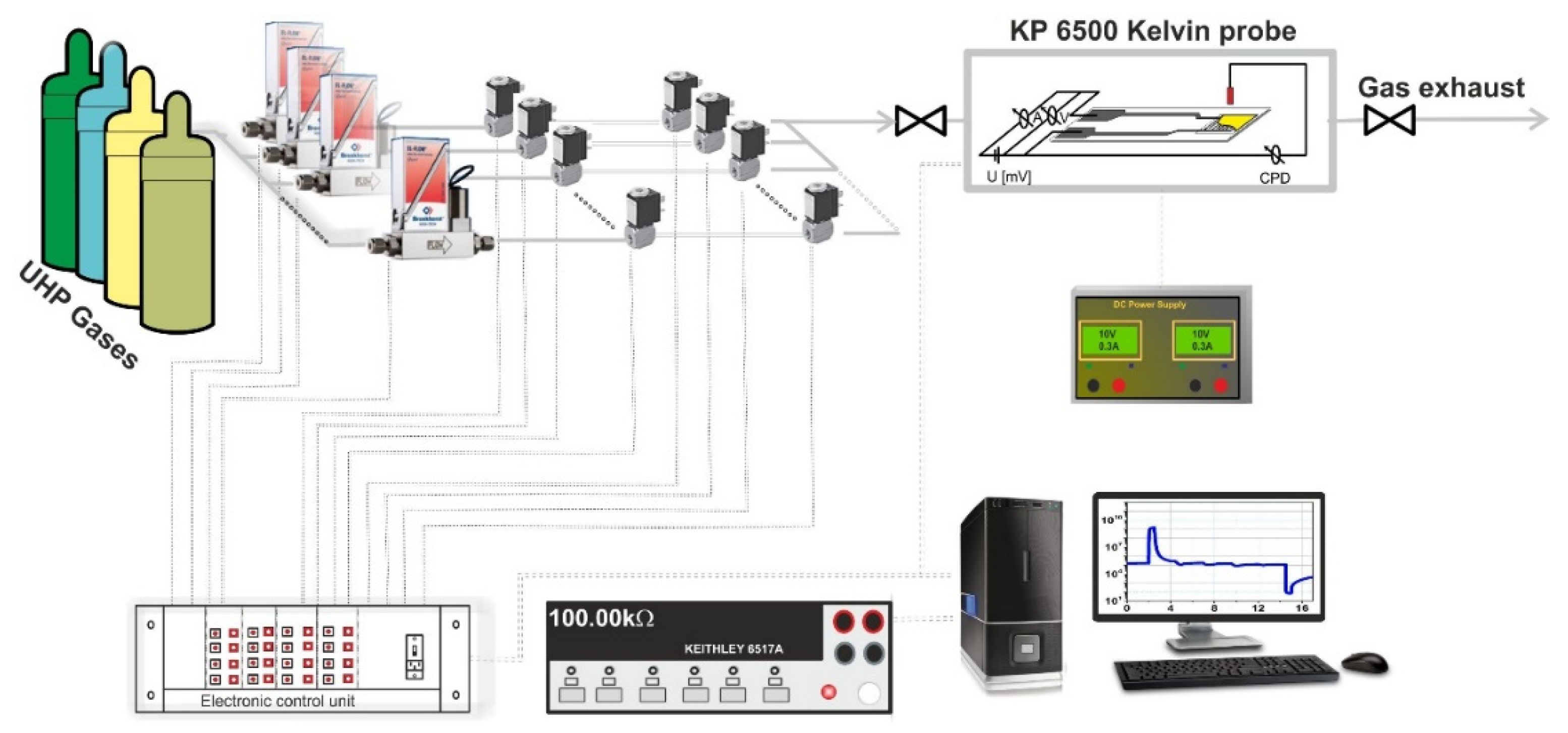
Figure 1. Experimental electrical setup for simultaneous measurements of electrical resistance and contact potential differences.
Chemosensors 10 00191 g001
Figure 2. XRD patterns of NiO as-prepared materials calcined at 400 °C and 500 °C.
Chemosensors 10 00191 g002
Figure 3. TEM images and the associated SAED patterns (inserted) of the as-prepared NiO nanoparticles for the samples calcinated at 400 °C (a) and 500 °C (b).
Chemosensors 10 00191 g003
Figure 4. HRTEM micrographs revealing the differences between the samples calcined at 400 °C (a,b) and 500 °C (c,d) in terms of nanoparticles size, shape, surface roughness, and presence of crystallographic defects. The white arrows in (c) point to typical planar defects observed inside a large single crystal nanoparticle in [01-1] orientation (sample calcined at 500 °C). The parallel planar defects in (d) are (−111) twin boundaries, while the zig-zag white line indicates the trace of the (200) crystallographic planes inside the nanoparticle across the twin boundaries.
Chemosensors 10 00191 g004
Figure 5. Deconvoluted Ni2p3/2 (a,b) and O1s high resolution spectra (c,d) for NiO cal@400 °C and NiO cal@500 °C.
Chemosensors 10 00191 g005
Figure 6. The sensor signal dependence with respect to the operating temperature for NiO-based gas sensors.
Chemosensors 10 00191 g006
Figure 7. Electrical resistance and CPD changes with respect to the CO concentration (a); potential changes under CO exposure for NiO calcined at 400 °C (b).
Chemosensors 10 00191 g007
Figure 8. Intuitive cartoon of CO-sensing mechanism with NiO calcined at 400 °C.
Chemosensors 10 00191 g008
Figure 9. Electrical resistance and CPD changes with respect to the CO concentration (a); potential changes under CO exposure for NiO calcined at 500 °C (b).
Chemosensors 10 00191 g009
Figure 10. Intuitive cartoon of CO-sensing mechanism with NiO calcined at 500 °C.
Chemosensors 10 00191 g010
Publisher’s Note: MDPI stays neutral with regard to jurisdictional claims in published maps and institutional affiliations.