
Impact Dynamics Analysis of Mobile Mechanical Systems


Abstract
:1. Introduction
- (1)
- Impact analysis for two bodies on a free-fall drop, which come in contact together, and
- (2)
- Impact study for a multi-body system from an internal combustion engine mechanism.
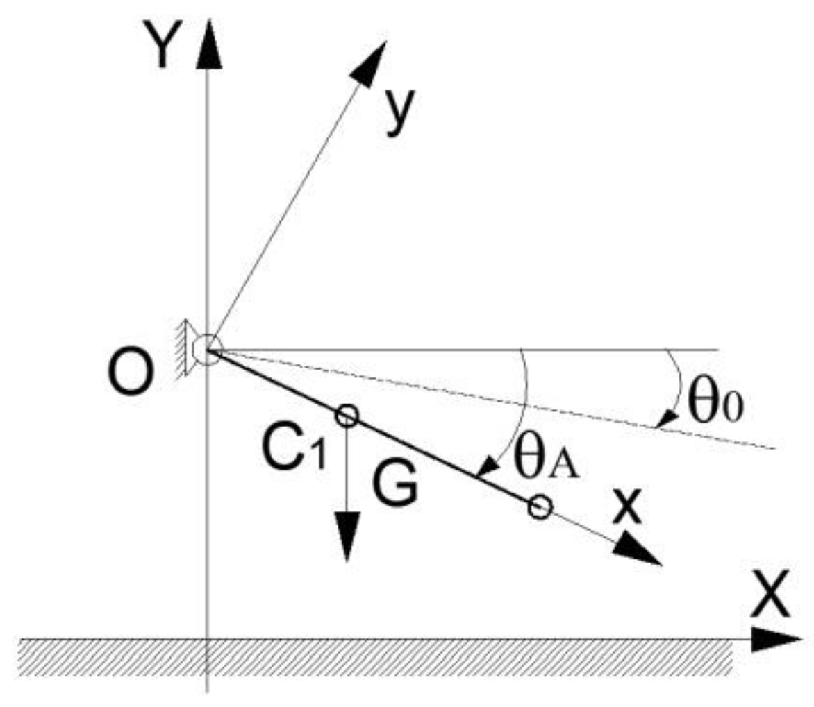
2. Impact Analysis of a Link with Planar Surface
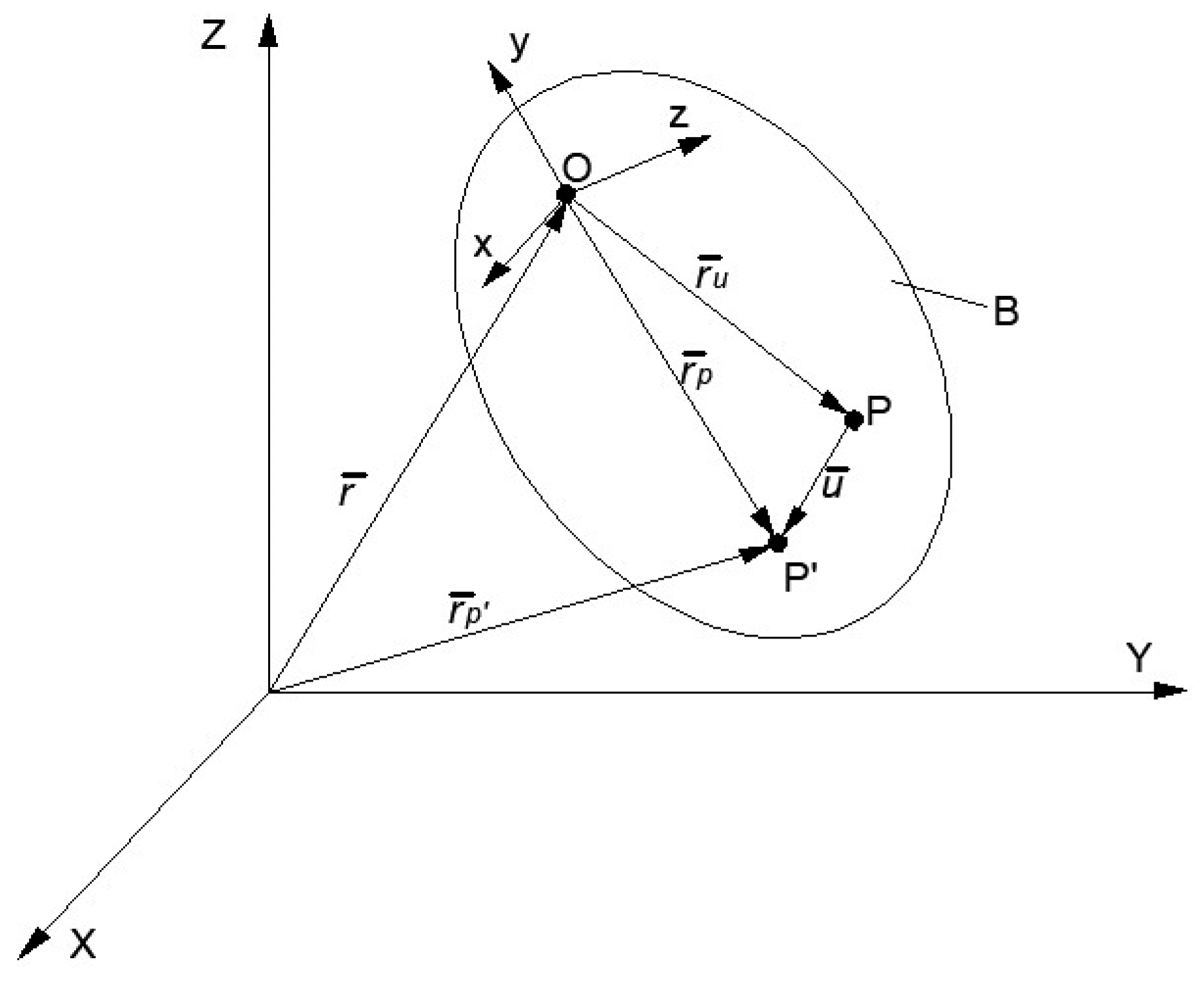
2.1. Analytical Method
Velocities
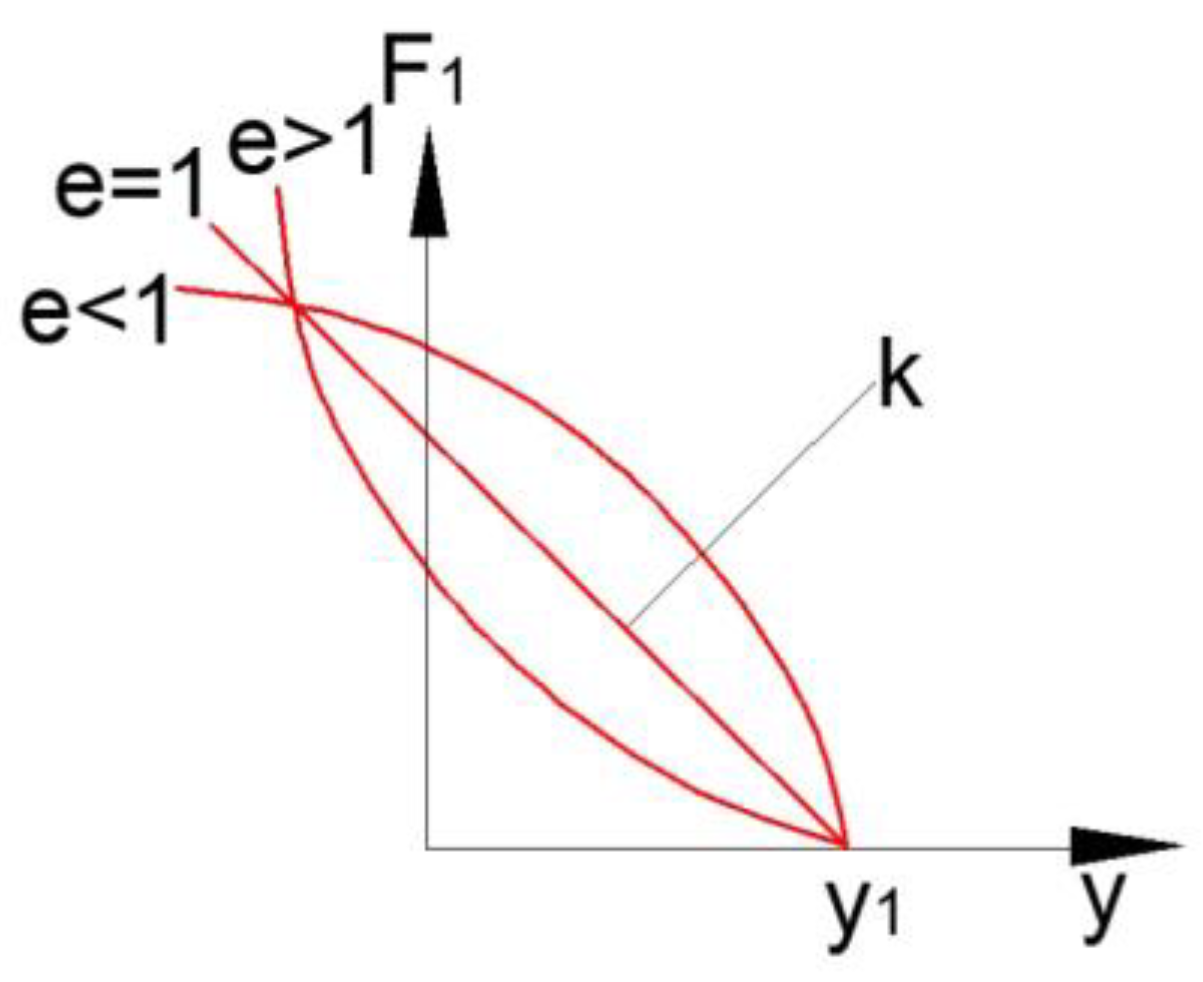
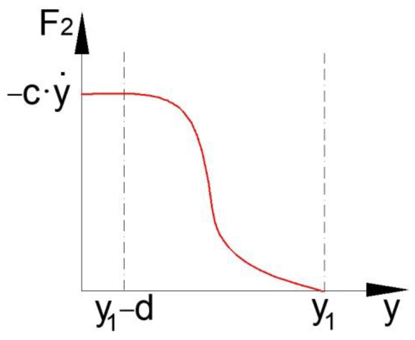
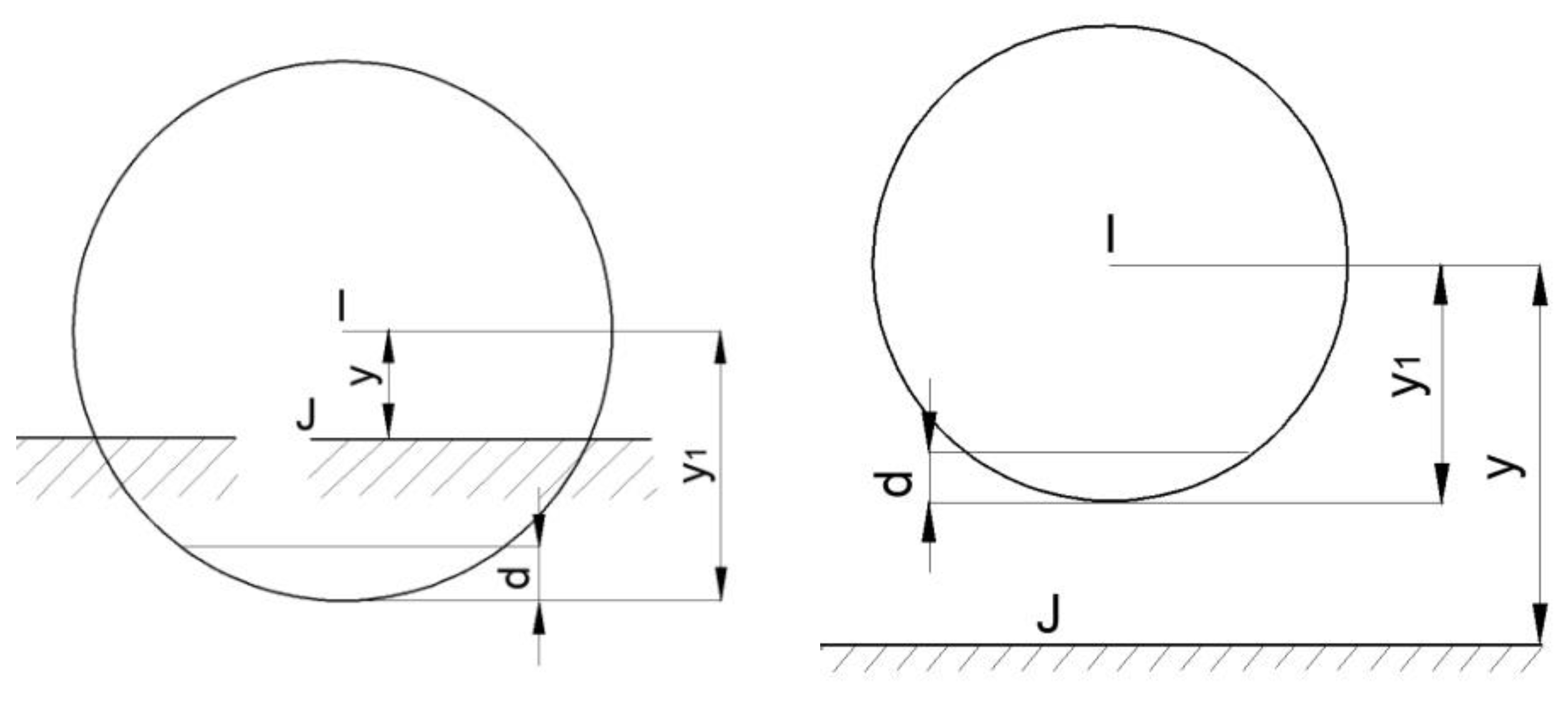
- if y ≥ y1, there will be no penetration at the level of the contact surface, and in this case the impact force will be equal to zero (penetration p = 0);
- if y < y1, penetration occurs at the end closer to the i marker, and the impact force is >0 (penetration p = y1 − y);
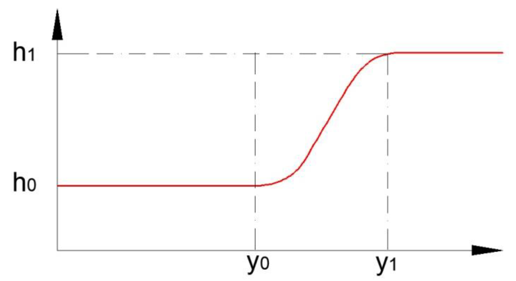
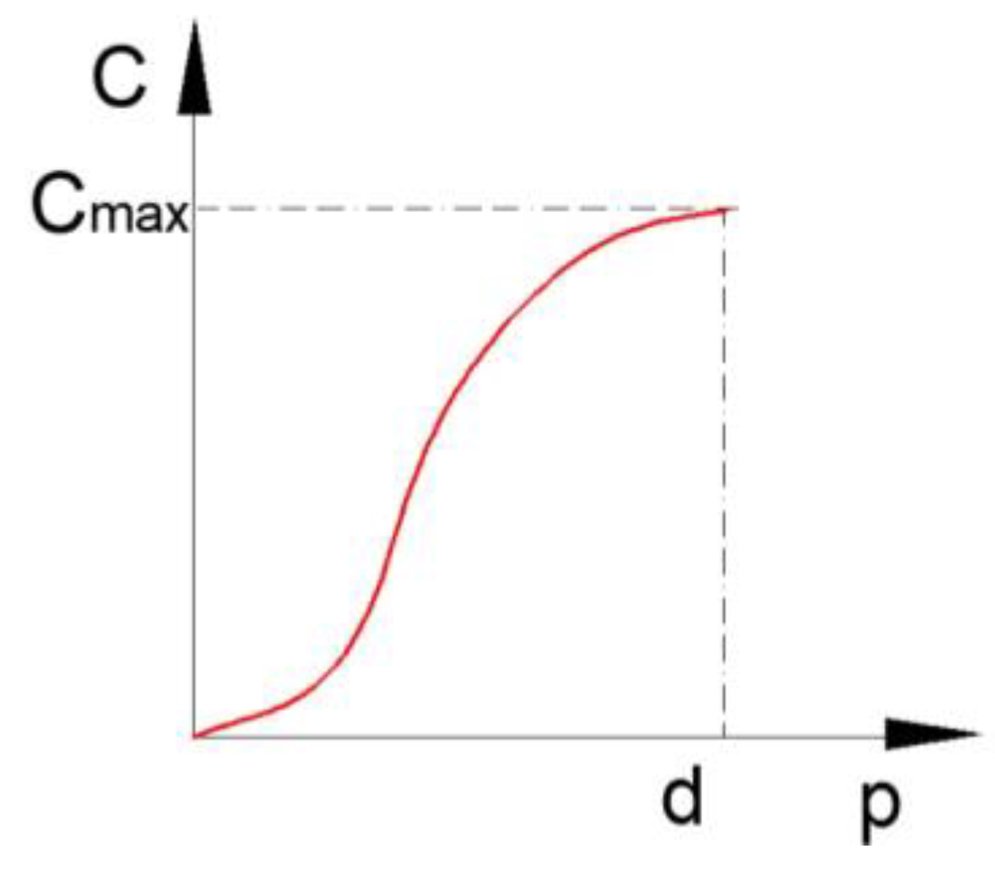
- when p < d, the damping instantaneous coefficient is a cubic STEP function of penetration, labeled p;
- when p > d, the instantaneous damping coefficient will be cmax.
- a spring or stiffness component and a damping or viscous component:
- damping (viscous component), which is a function of the speed of penetration.
| Algorithm 1 Programming Sequence for Time Intervals |
| for t from 0 by 0.0001 to 0.6 do if print ; then print else print end if end do; |
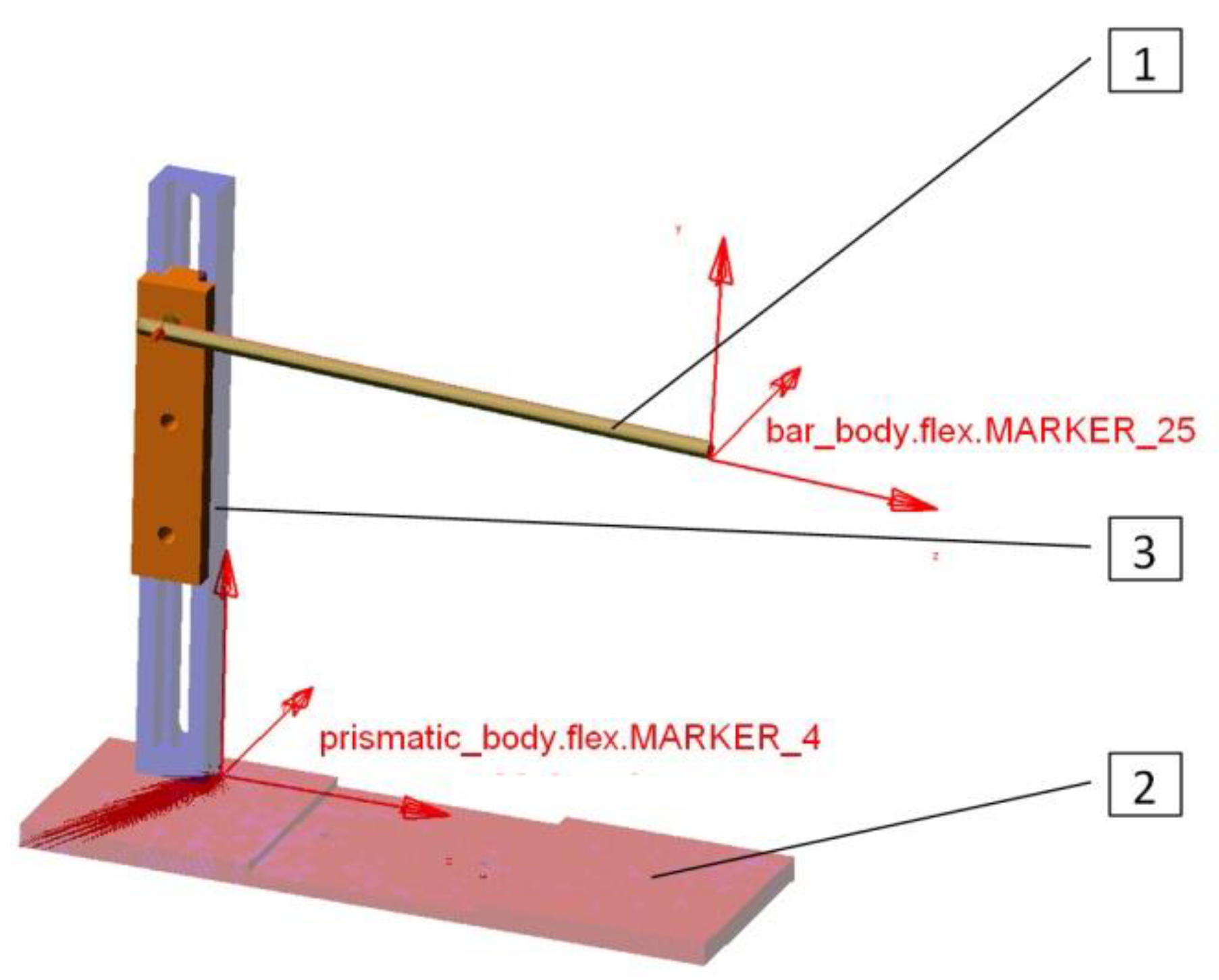
2.2. Impact Modeling with MSC Adams
2.3. Impact Analysis with Finite Element Method
2.4. Impact Modeling with Abaqus
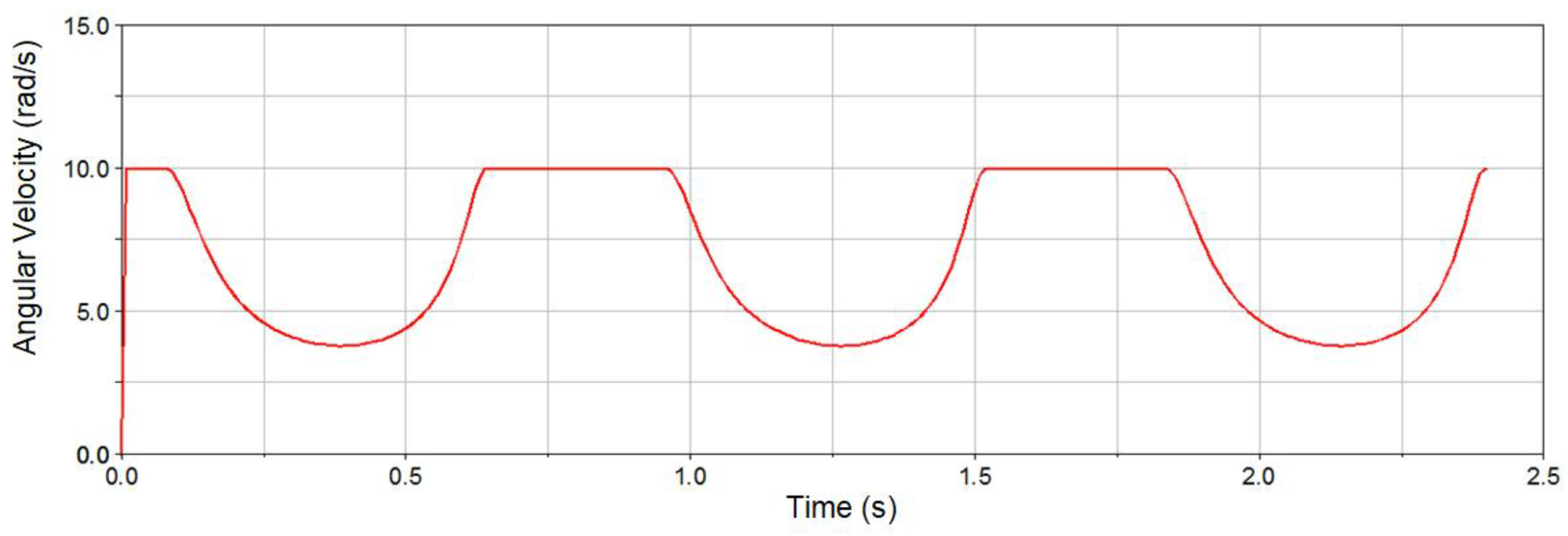
3. Dynamic Analysis of the Impact in the Case of a Crank-Connecting Rod Mechanism
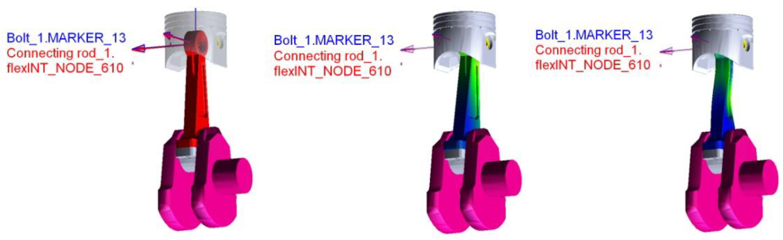
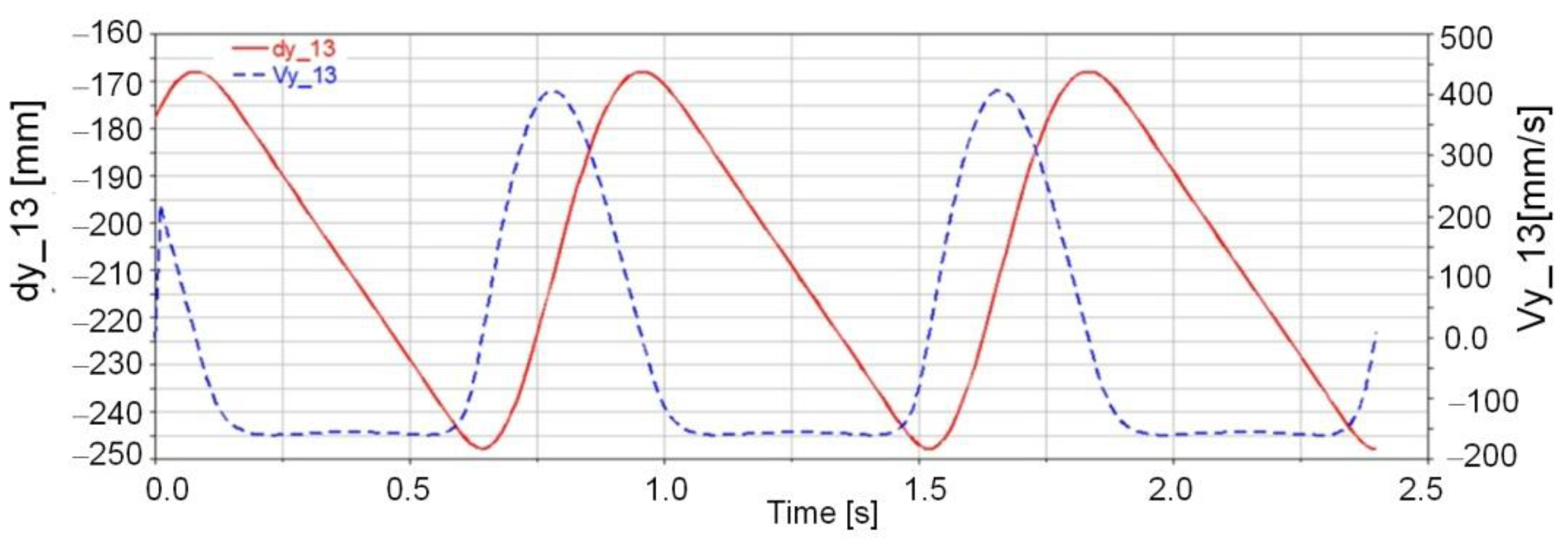
- time variation functions are defined for the interest marker displacement and velocity (the marker that materializes the force point application, i.e., marker 13, placed in the joint rotation center);
- the impact function will be created based on the following kinematic and dynamic parameters: displacement, dy_ MARKER_i, velocity, vy_ MARKER_i, for marker i, stiffness k, exponential coefficient e, damping c, penetration d, as follows:
3.1. Impact Dynamic Analysis with Rigid Elements
3.2. Impact Dynamic Analysis with Deformable Elements
3.2.1. Mathematical Considerations
- Evaluating the natural frequencies and vibration modes;
- Elastic dynamic analysis.
3.2.2. Numerical Simulation
- modal-dynamic analysis with calculating the engine torque for the mechanism actuation;
- kinematic and dynamic parameters analysis of the generated contact during the impact between the bolt and the connecting rod head.
4. Results and Conclusions
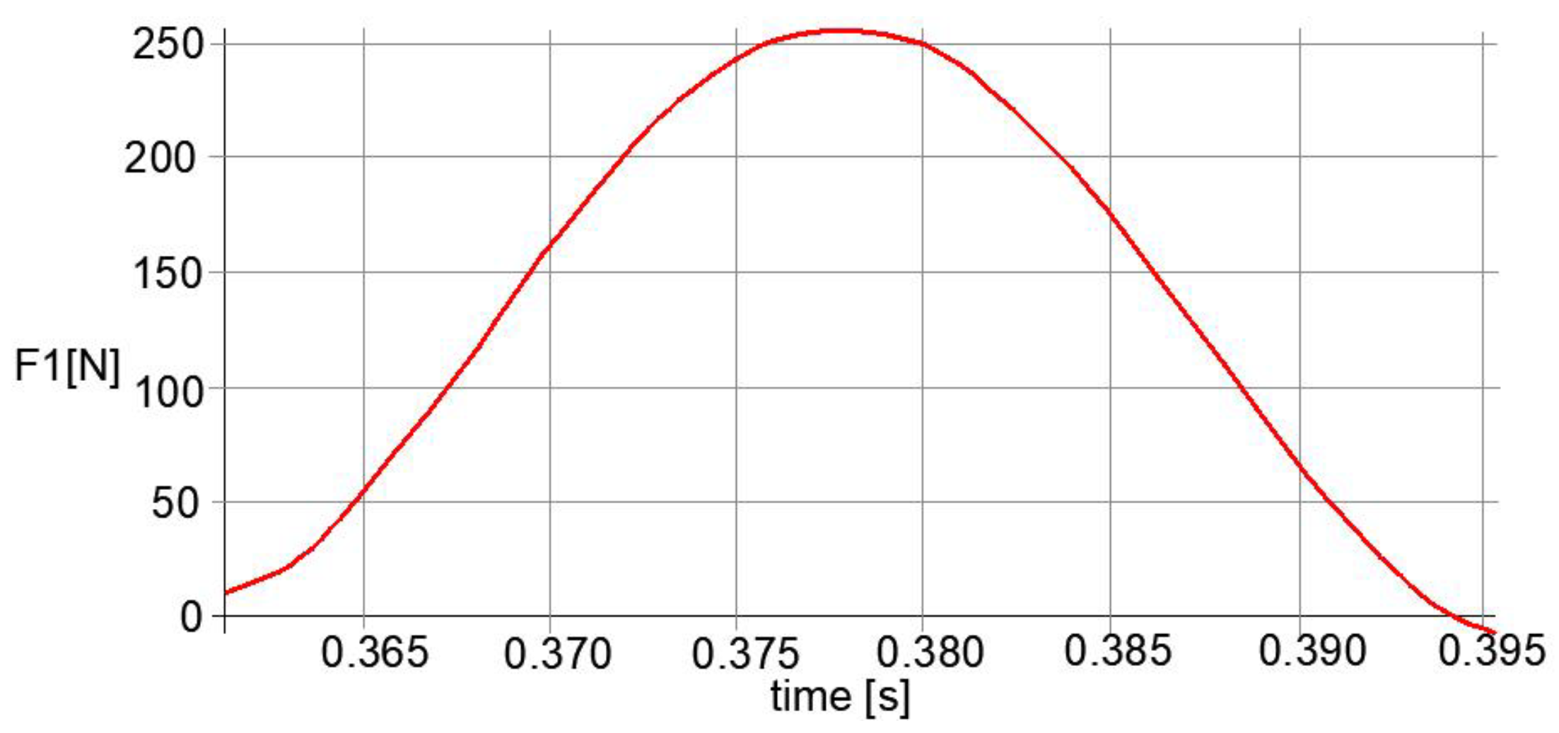
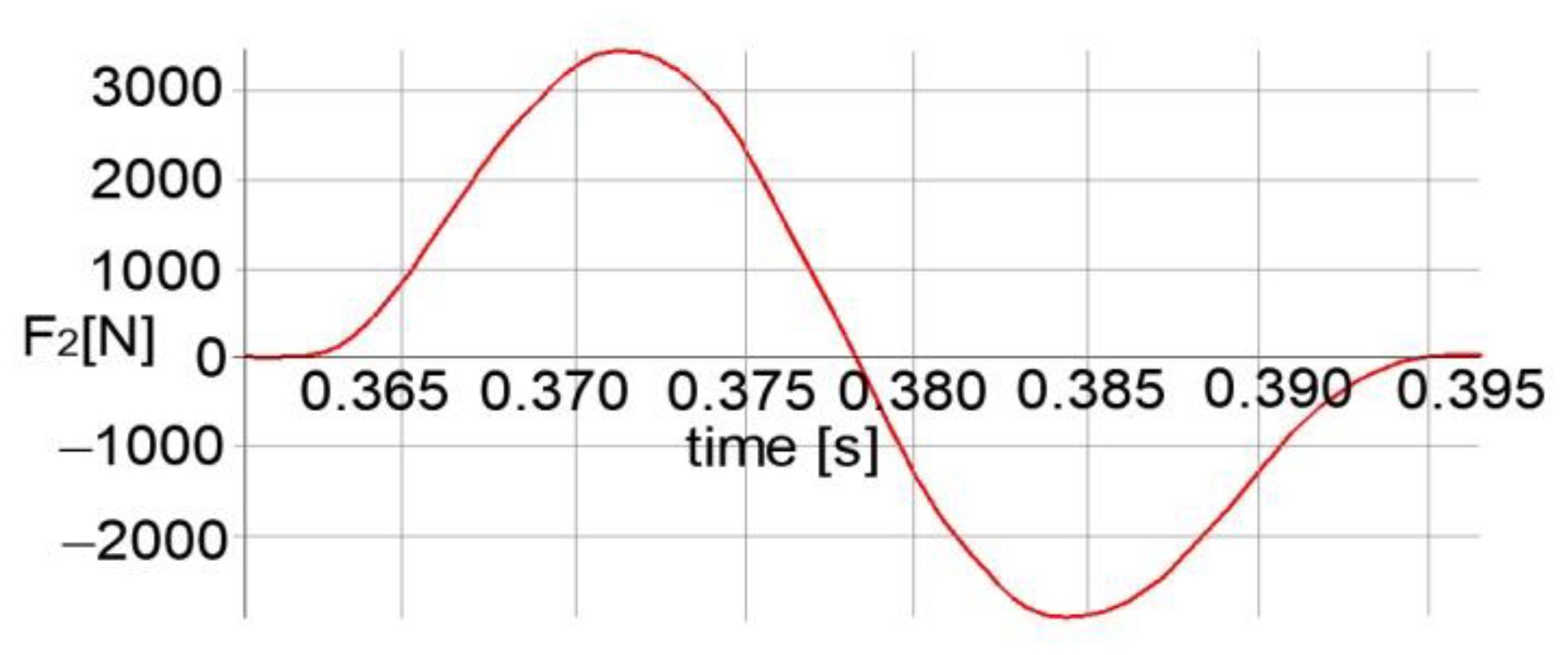
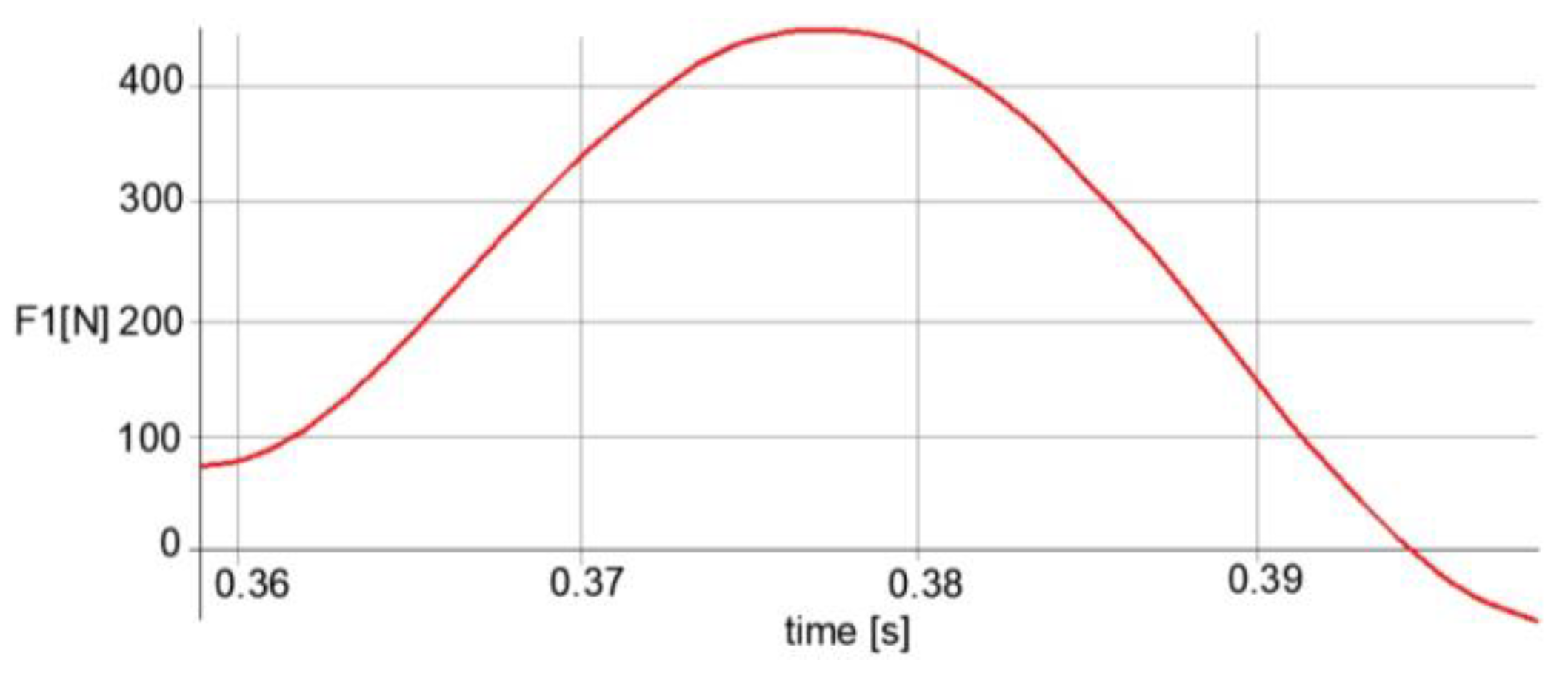
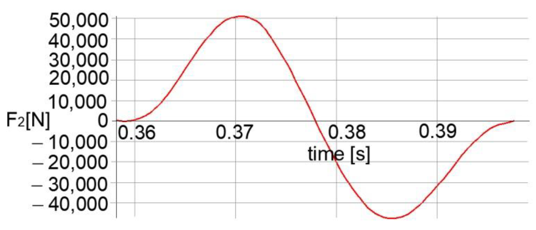
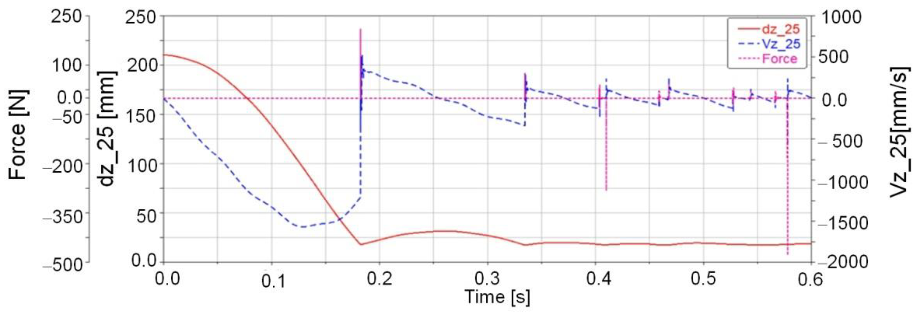
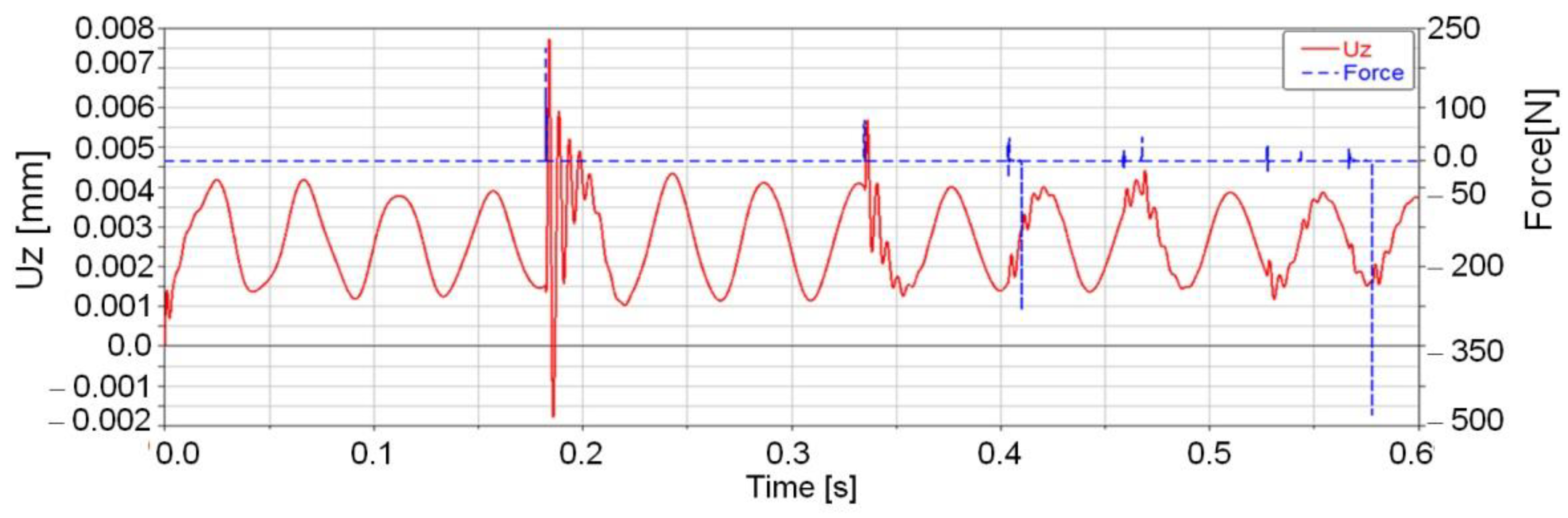
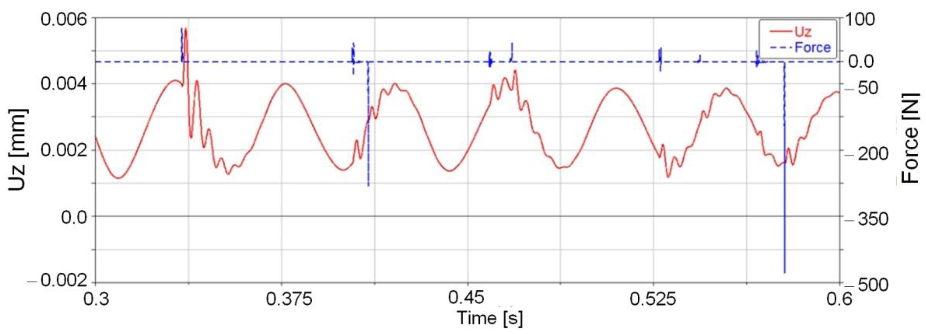
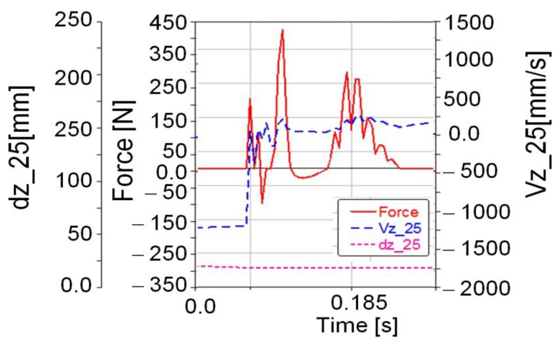
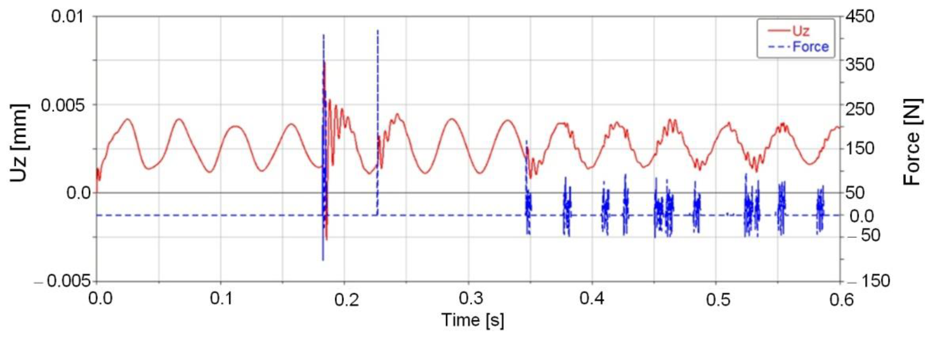
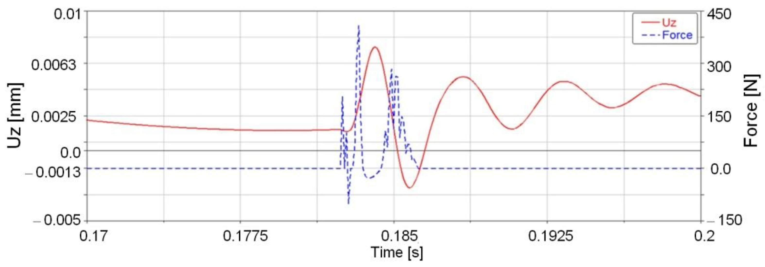
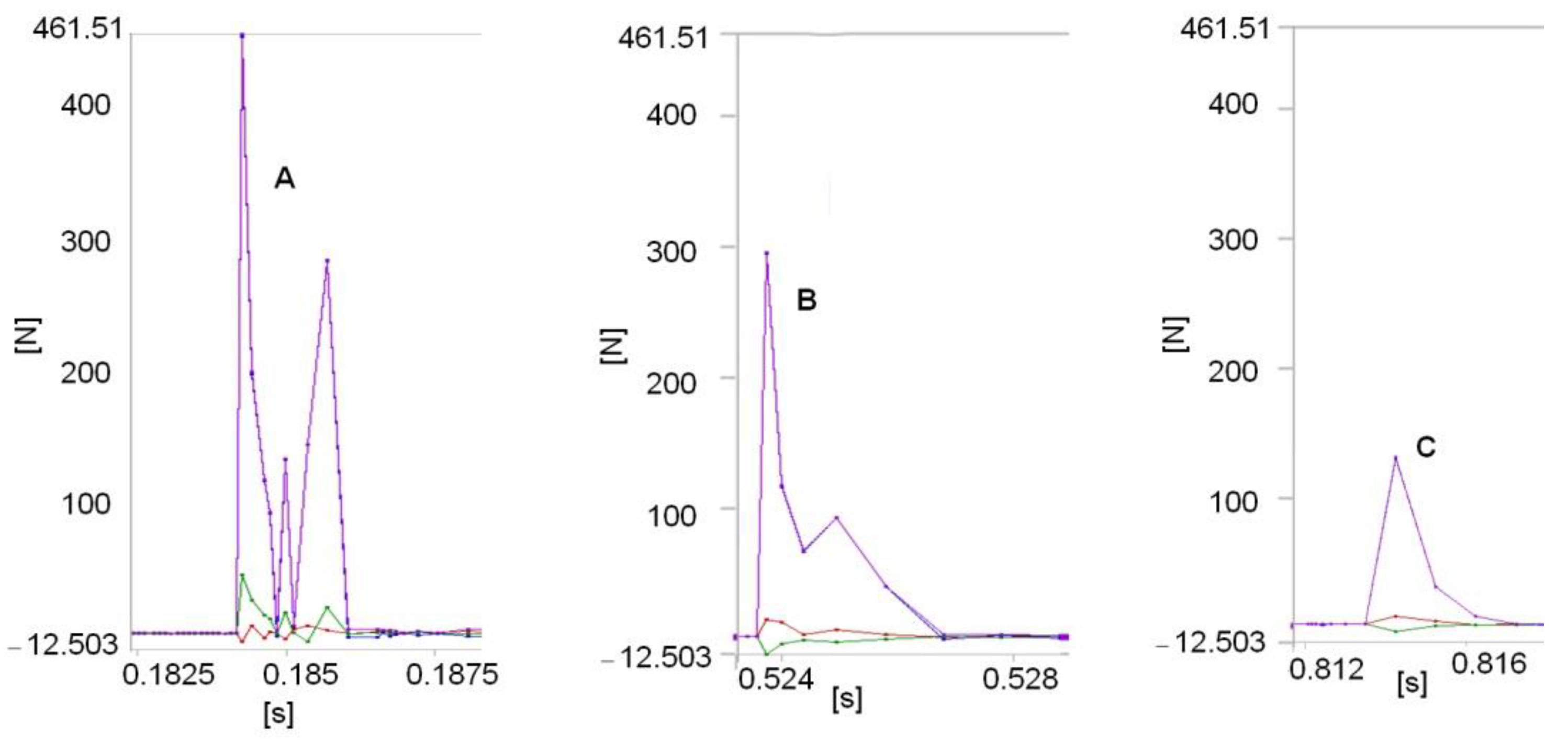
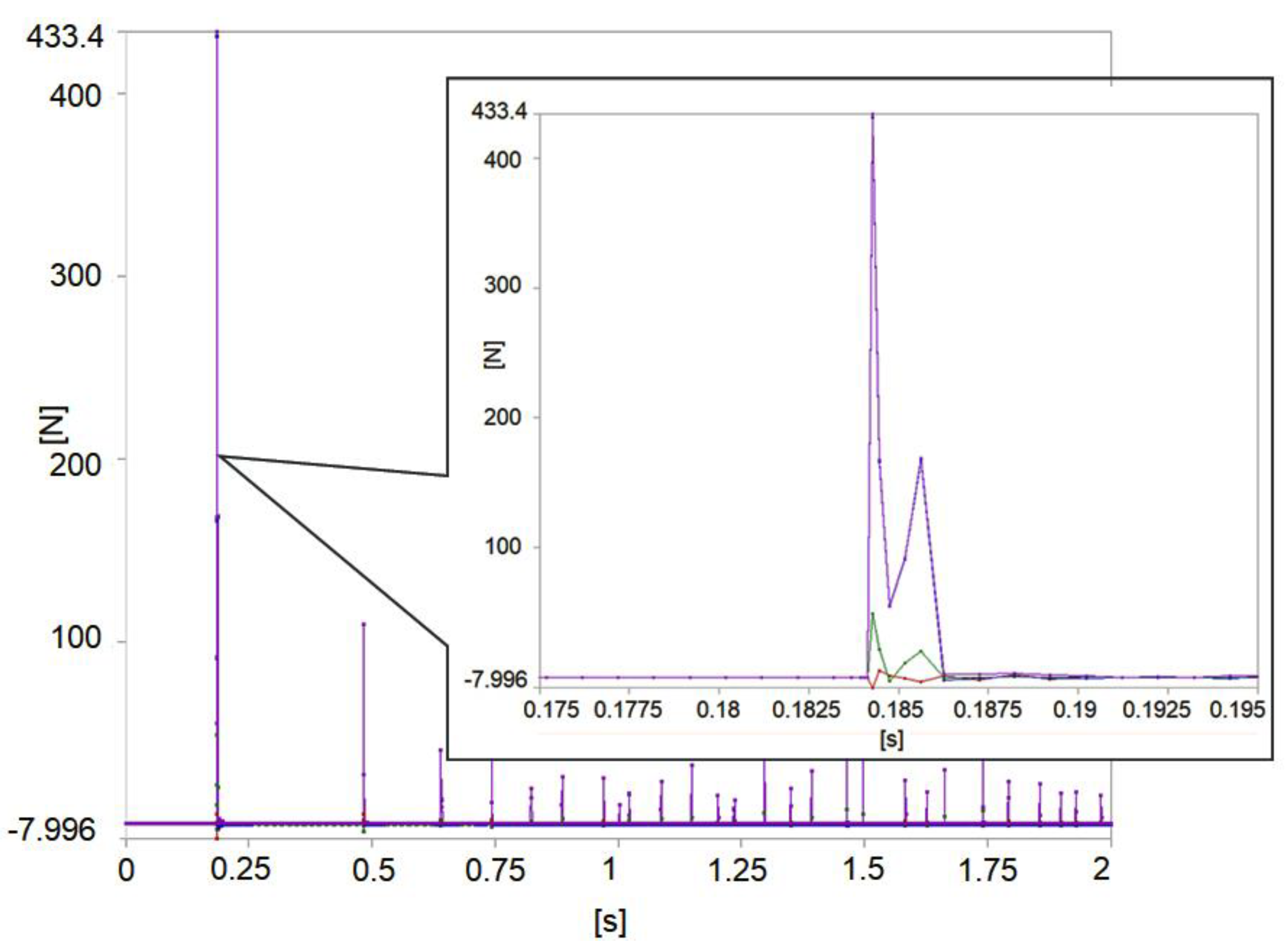
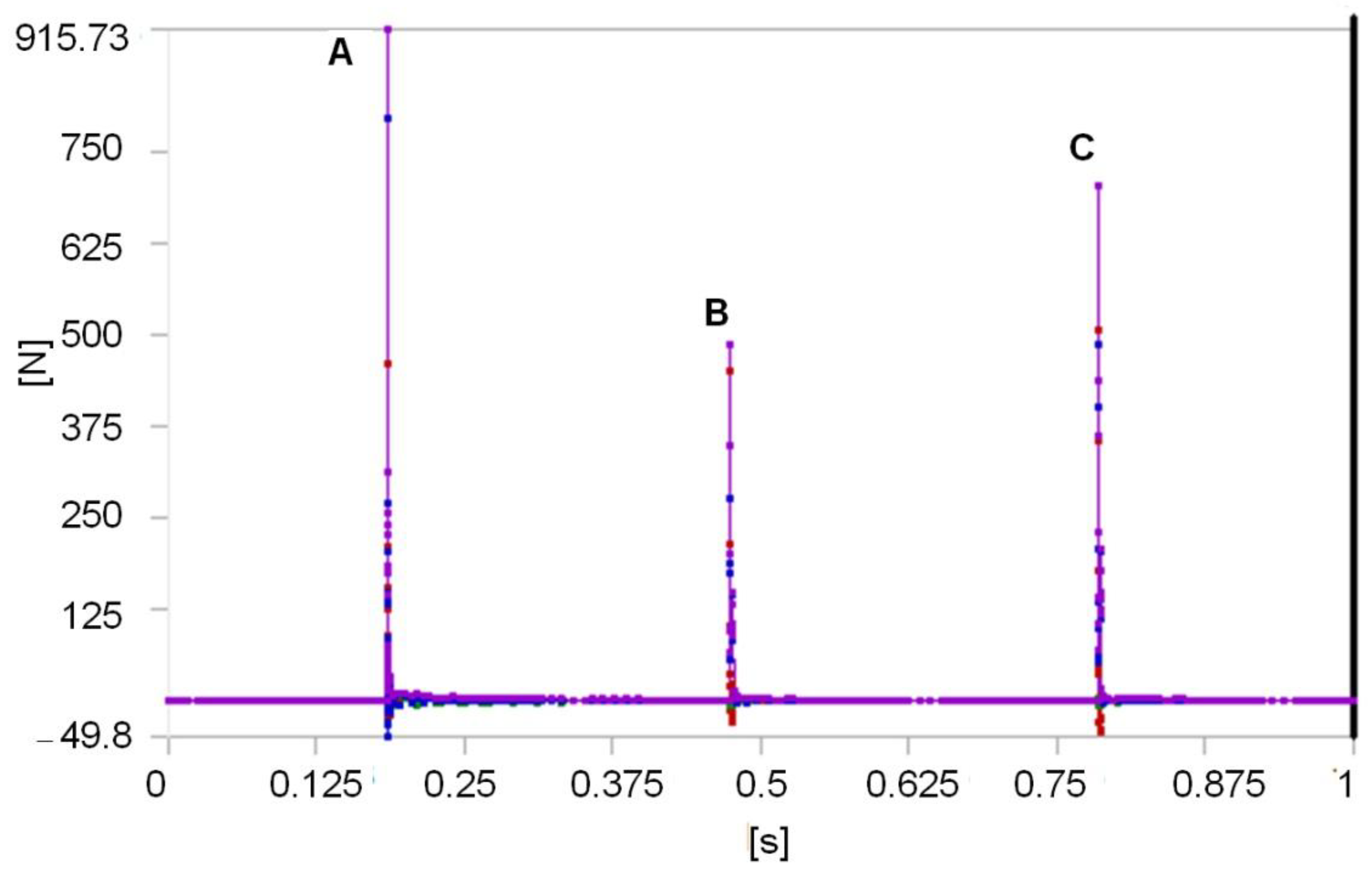
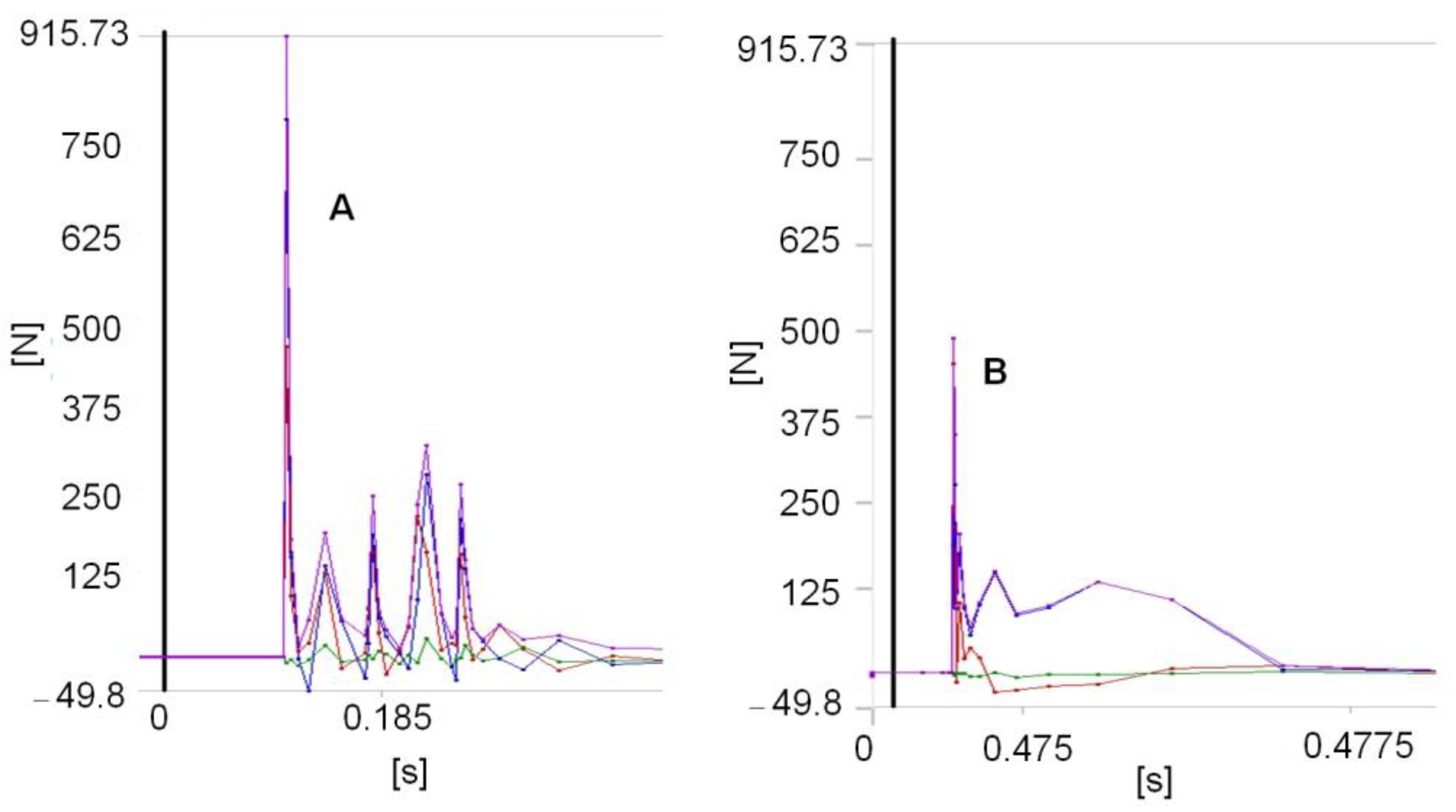
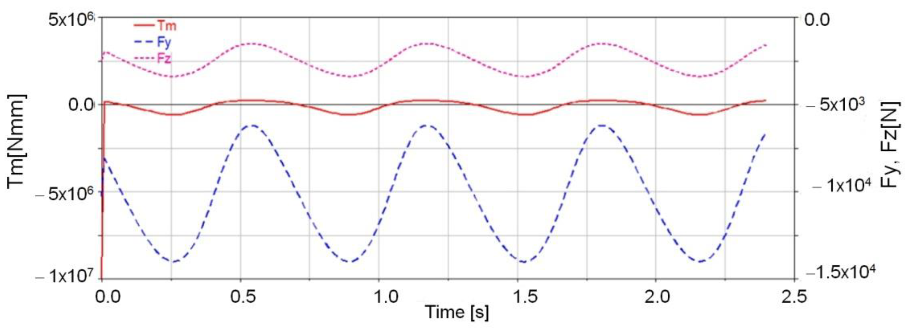
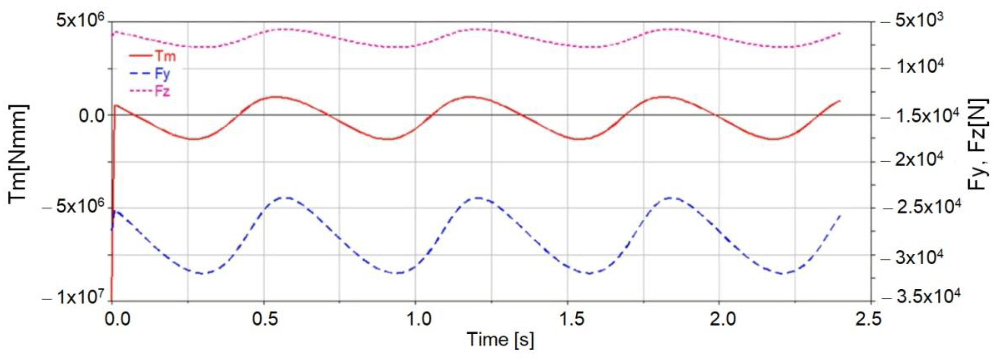
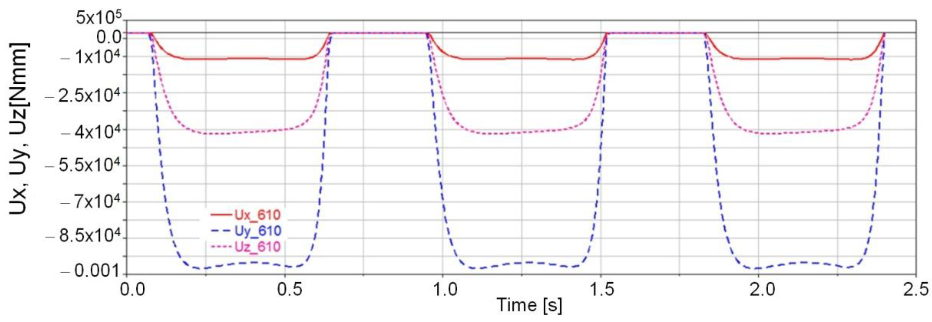
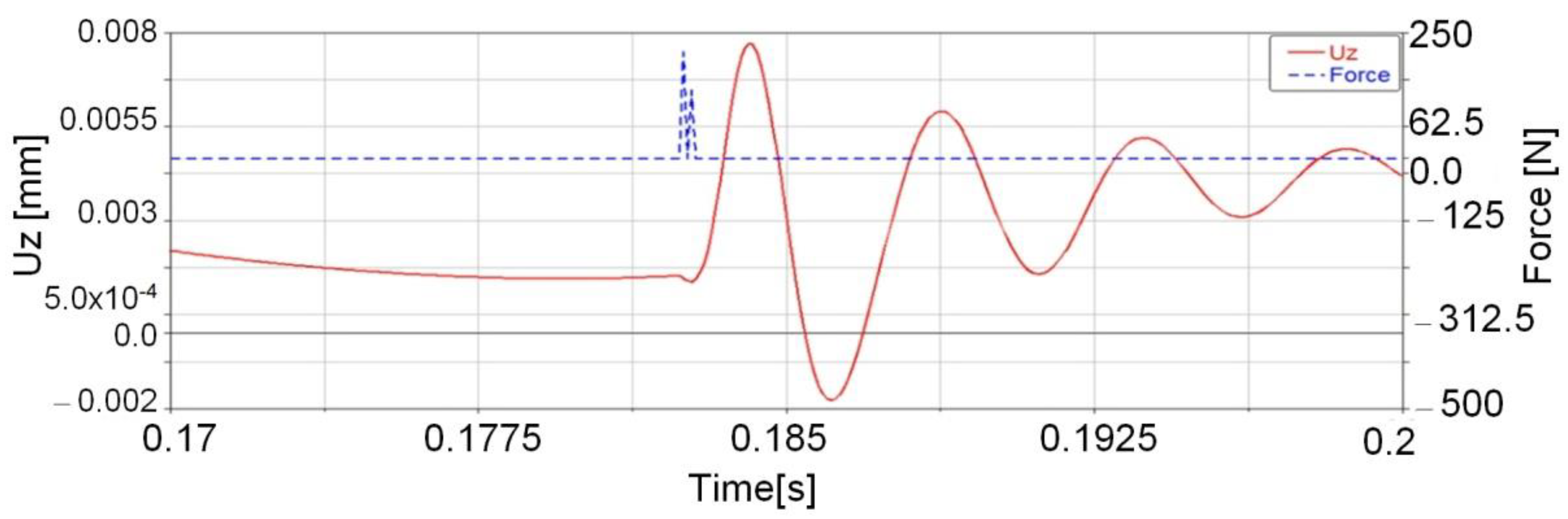
- The mathematical model corresponding to Equation (16) is compatible with the Adams software theory, in relation to the impact phenomenon analysis. A Maple program sequence was derived, which can be numerically processed based on the created mathematical models by considering two major impact force components, namely, the stiffness component and the viscous component. These component variations with time were presented in Figure 7 and Figure 8.
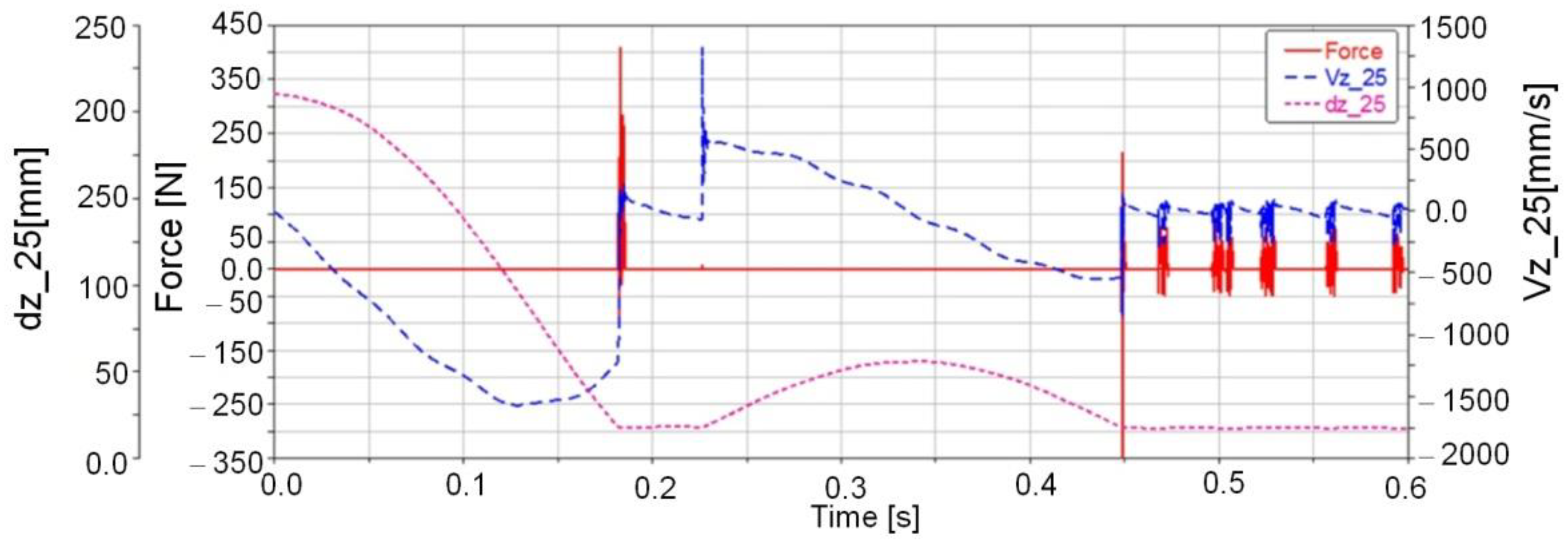
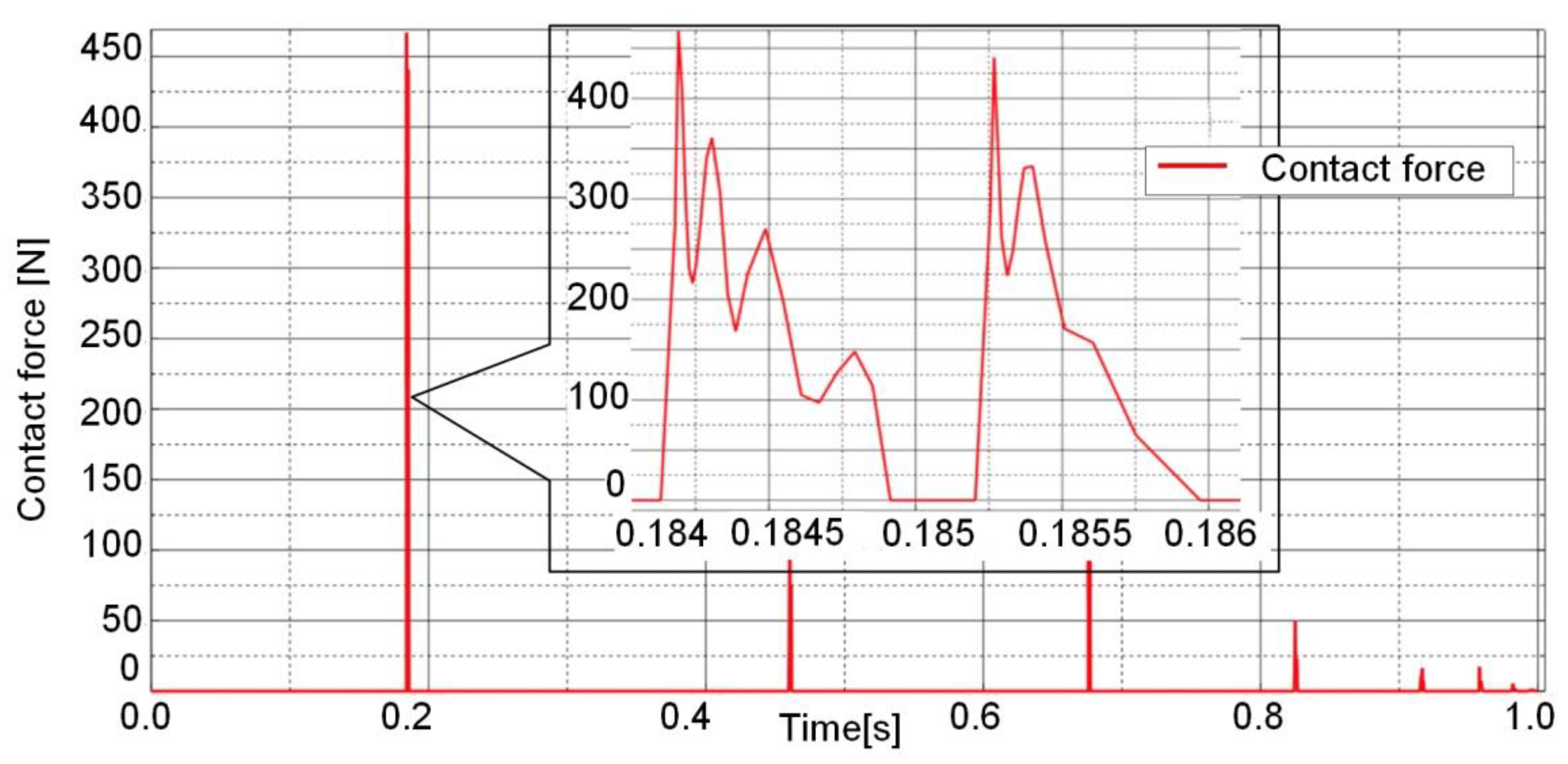
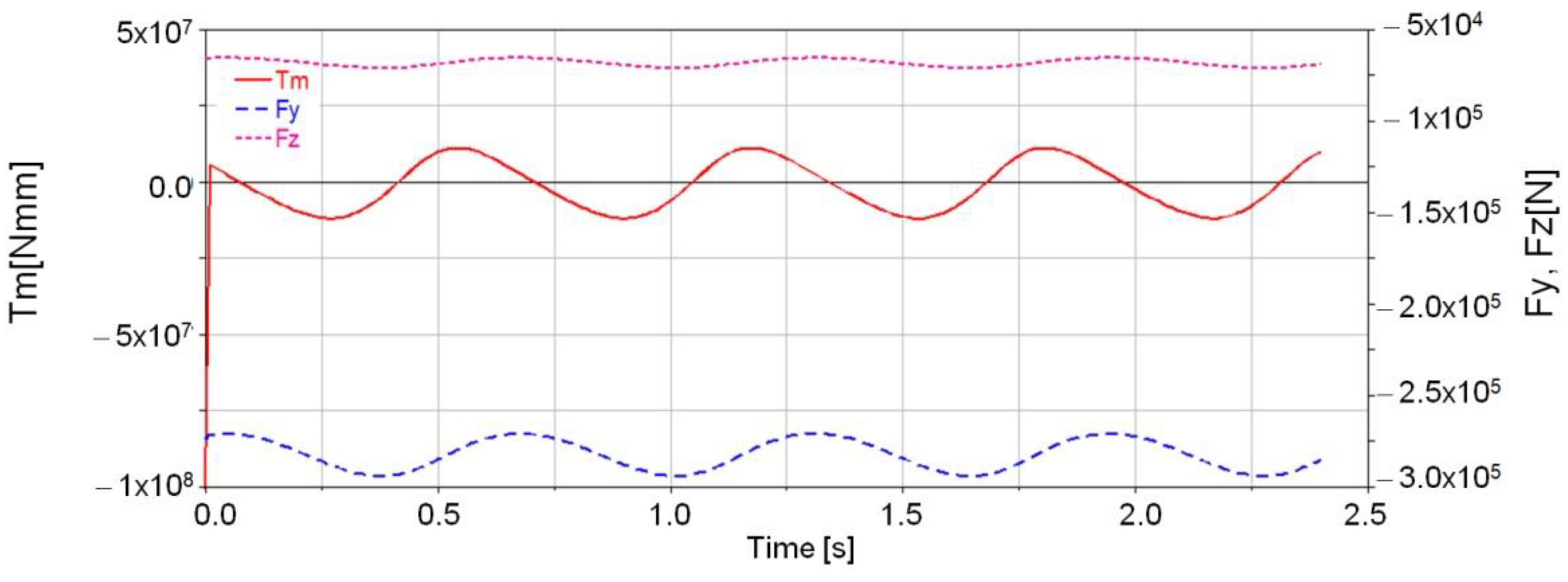
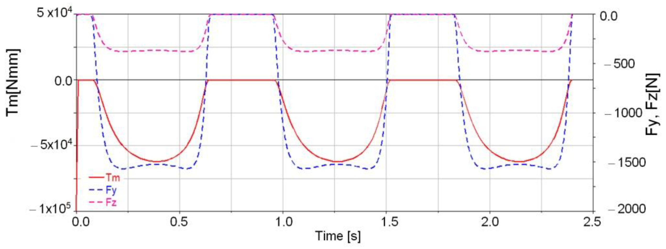
- The dynamic parameters were processed via the Maple program by considering Equation (16) with the numerical values indicated in Figure 7 and these corresponds to the virtual models obtained with the Adams software (Figure 16 and Figure 17), with Ansys software (Figure 24) and Abaqus software (Figure 28), respectively.
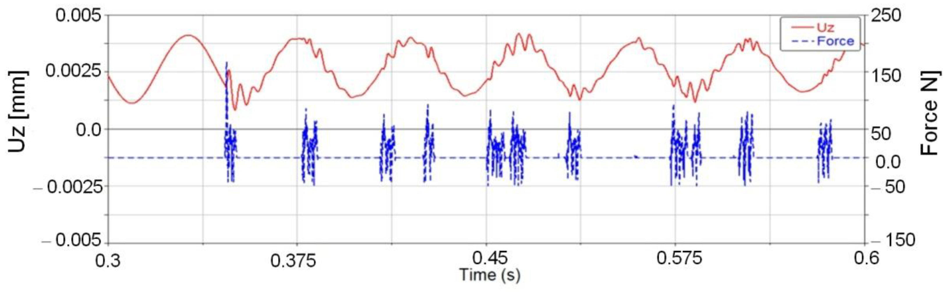
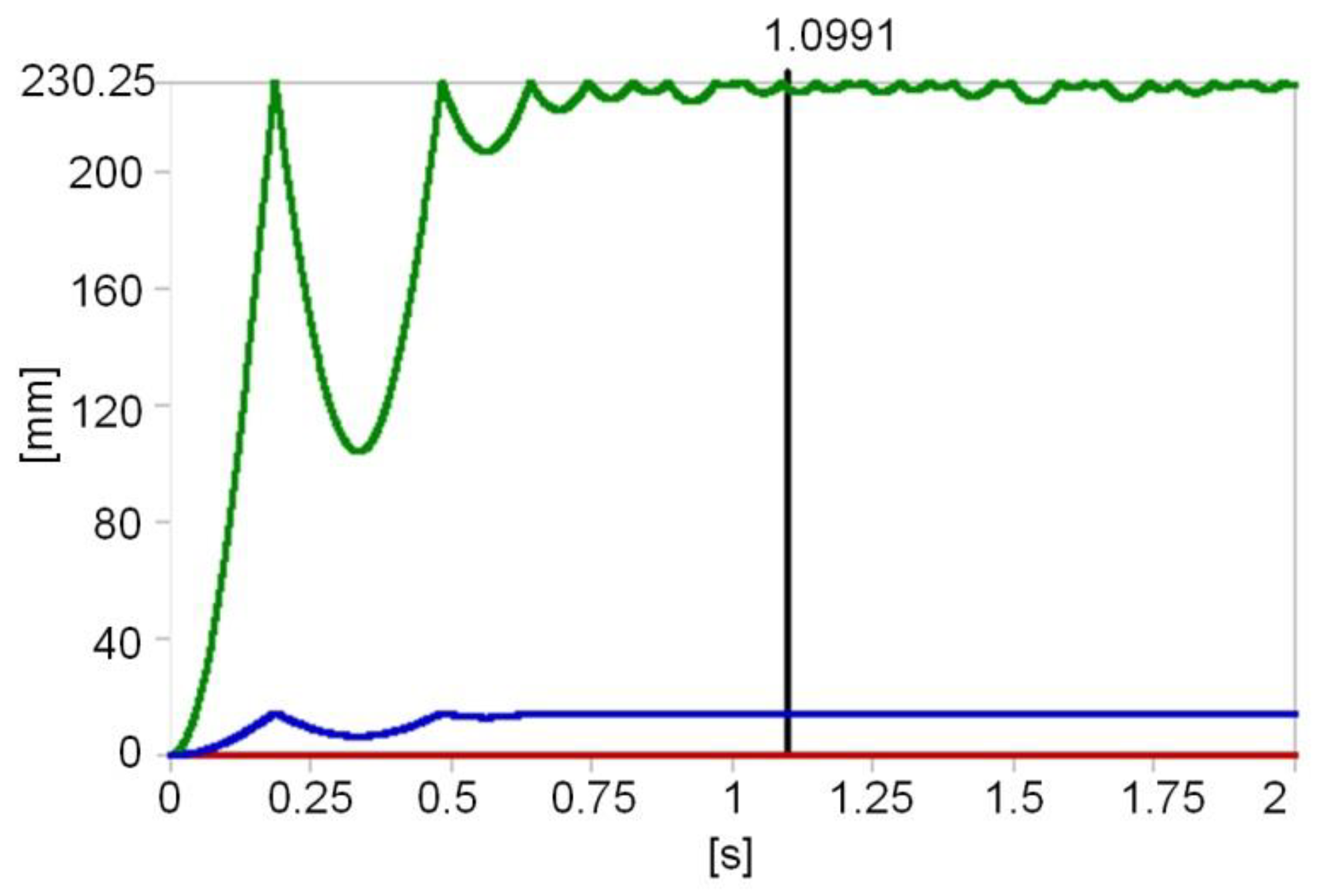
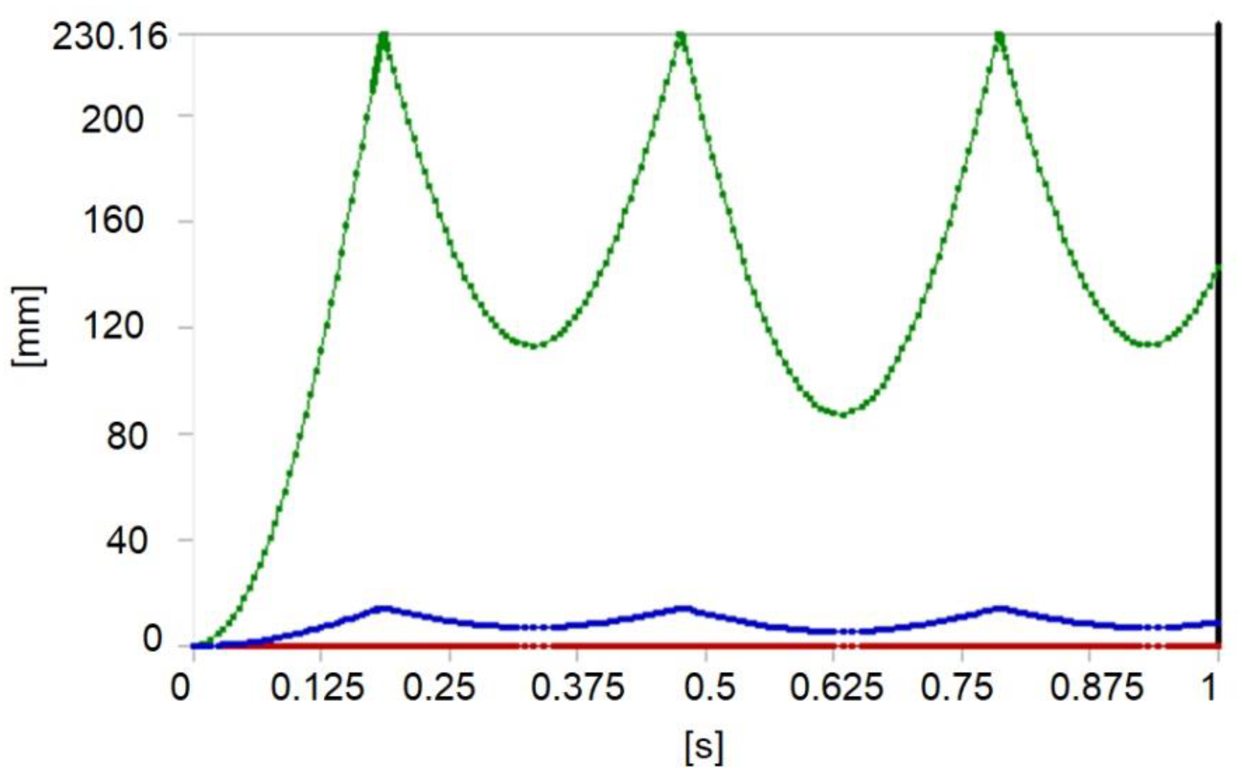
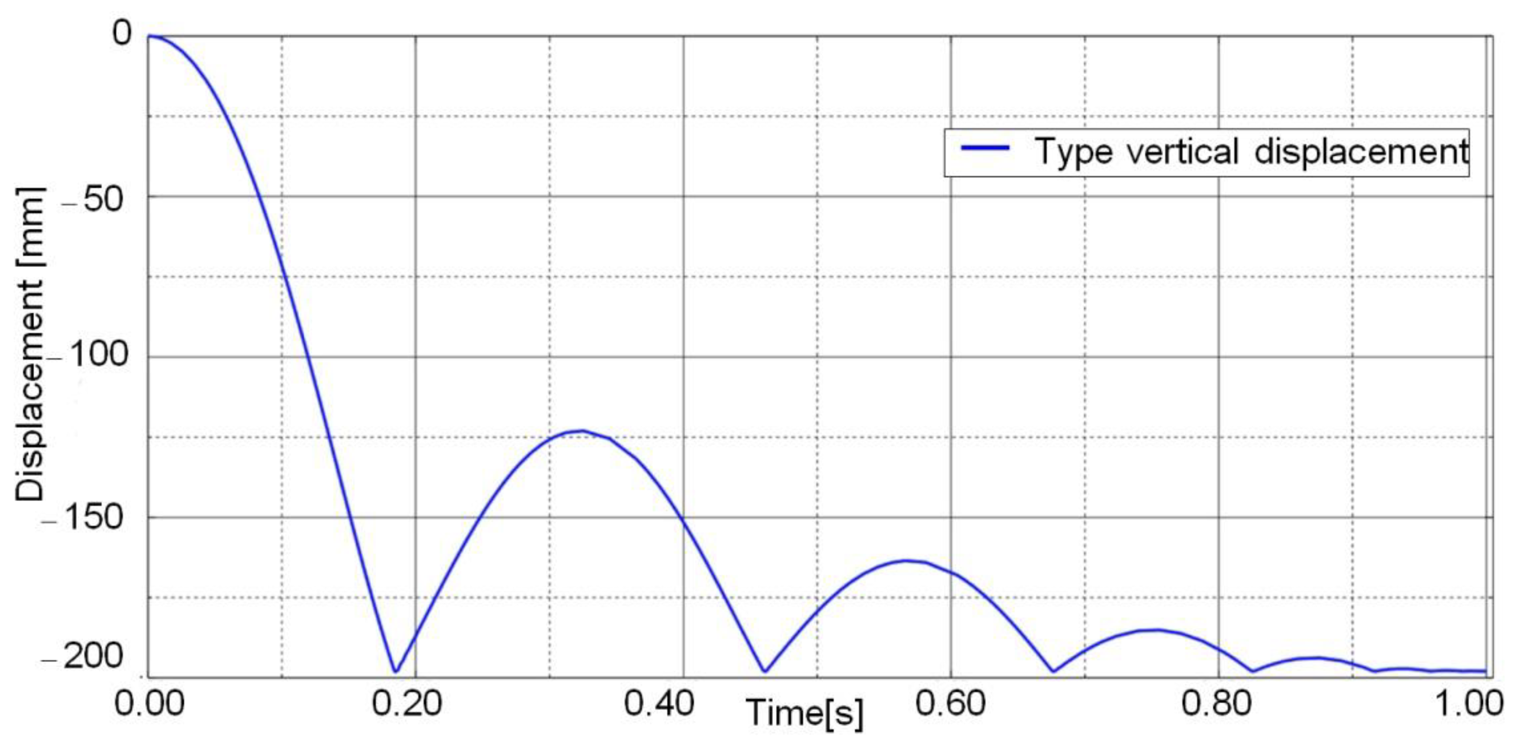
- For the analytical models and numerical processing of the imported models with the Adams software, the bar component motion was monitored in a time interval equal to 0.6 s.
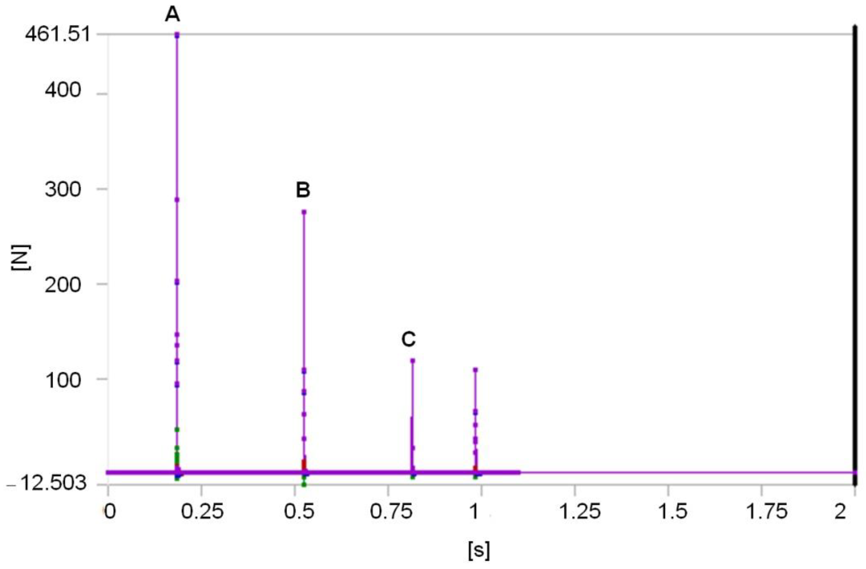
- By modifying the damping coefficient value to c = 6, it can be remarked that the impact force maximum value will be modified, as well, along the number of contacts between the bar component and the prismatic body. At the same damping coefficient, by keeping the contact conditions and the integration step of the equations system, which dictate the bar component motion, one can see that the impact force values are not compatible with these cases, namely, analytical case (Figure 9), numerical simulation with the Adams software (Figure 16) and the finite element analysis (Figure 24 and Figure 28).
Author Contributions
Funding
Institutional Review Board Statement
Informed Consent Statement
Data Availability Statement
Conflicts of Interest
References
- Ambrósio, J.A.C. Impact of rigid and flexible multibody systems deformation description and contact models. In Virtual Nonlinear Multibody Systems; Springer: Dordrecht, The Netherlands, 2003; pp. 57–81. [Google Scholar]
- Khulief, Y.A.; Haug, E.J.; Shabana, A.A. Dynamic Analysis of Large Scale Mechanical Systems with Intermittent Motion; Technnical Report No. 83-10; University of Iowa, College of Engineering: Iowa City, IA, USA, 1983. [Google Scholar]
- Hunt, K.H.; Grossley, F.R.E. Coefficient of Restitution Interpreted as Damping in Vibroimpact. ASME J. Appl. Mech. 1975, 42, 440–445. [Google Scholar] [CrossRef]
- Ahmed, S.; Lankarani, H.M.; Pereira, M.F.O.S. Frictional impact analysis in open-loop multibody mechanical systems. J. Mech. Des. 1999, 121, 119–127. [Google Scholar] [CrossRef]
- McCoy, M.l.; Lankarani, H.; Moradi, R. Use of simple finite elements for mechanical systems impact analysis based on stereomechanics, stress wave propagation, and energy method approaches. J. Mech. Sci. Technol. 2011, 25, 783–795. [Google Scholar] [CrossRef]
- Tempelman, E.; Dwaikat, M.M.S.; Spitás, C. Experimental and Analytical Study of Free-Fall Drop Impact. Testing of Portable Products. Exp. Mech. 2012, 52, 1385–1395. [Google Scholar] [CrossRef] [Green Version]
- Kantar, E.; Erdem, R.; Ozgur, A. Nonlinear Finite Element Analysis of Impact Behavior of Concrete Beam. Math. Comput. Appl. 2011, 16, 183–193. [Google Scholar] [CrossRef] [Green Version]
- Chen, C.-R.; Wu, C.-H.; Lee, H.-T. Determination of Optimal Drop Height in Free-Fall Shock Test Using Regression Analysis and Back-Propagation Neural Network. Shock Vib. J. 2014. [Google Scholar] [CrossRef] [Green Version]
- Corbin, N.A.; Hanna, J.A.; Royston, W.R.; Warner, R.B. Impact-induced acceleration by obstacles. New J. Phys. 2018, 20, 1–8. [Google Scholar] [CrossRef]
- Brun, P.-T.; Audoly, B.; Goriely, A.; Vella, D. The surprising dynamics of a chain on a pulley: Lift off and snapping. Proc. R. Soc. A Math. Phys. Eng. Sci. 2016, 472, 20160187. [Google Scholar] [CrossRef] [PubMed]
- Dankowicz, H.; Fotsch, E. On the analysis of chatter in mechanical systems with impacts. Procedia IUTAM 2017, 20, 18–25. [Google Scholar] [CrossRef]
- King, H.; White, R.; Maxwell, I.; Menon, N. Inelastic impact of a sphere on a massive plane: Nonmonotonic velocity dependence of the restitution coefficient. Europhys. Lett. 2011, 93, 14002. [Google Scholar] [CrossRef]
- Muller, P.; Heckel, M.; Sack, A.; Poschel, T. Complex velocity dependence of the coefficient of restitution of a bouncing ball. Phys. Rev. Lett. 2013, 110, 254301. [Google Scholar] [CrossRef] [PubMed] [Green Version]
- Yan, M.; Wang, T. Finite Element Analysis of Cylinder Piston Impact Based on ANSYS/LS-DYNA. In Proceedings of the 2012 International Conference on Mechanical Engineering and Material Science (MEMS 2012), Hong Kong, China, 27–28 July 2012. [Google Scholar]
- Žmindák, M.; Pelagić, Z.; Pastorek, P.; Močilan, M.; Vybošťok, M. Finite Element Modelling of High Velocity Impact on Plate Structures. Procedia Eng. 2016, 136, 162–168. [Google Scholar] [CrossRef] [Green Version]
- Wittenburg, J. Dynamics of Systems of Rigid Bodies. Leitfäden der Angewandten Mathematik und Mechanik; Springer: Berlin/Heidelberg, Germany, 1977. [Google Scholar]
- Wehage, R.A. Generalized Coordinate Partitioning in Dynamic Analysis of Mechanical Systems. Ph.D. Thesis, University of Iowa, Iowa, IA, USA, 1980. [Google Scholar]
- Haug, E.J.; Wu, S.C.; Yang, S.M. Dynamics of Mechanical Systems with Coulomb Friction, Stiction, Impact and Constraint Addition and Deletion, I. Mech. Mach. Theory 1986, 21, 401–406. [Google Scholar] [CrossRef]
- Lankaram, M.H.N.; Kravesh, P.E. Application of the Canonical Equations of Motion in Problems of Constrained Multibody Systems with Intermittent Motion. In Proceedings of the 14-th ASME Design Automation Conference, Advances in Design Automation, Kissimmee, FL, USA, 25–28 September 1988; Volume 14, pp. 417–423. [Google Scholar]
- Flores, P.; Ambrósio, J.; Claro, J.P.; Lankarani, H.M. Contact-impact force models for mechanical systems. In Kinematics and Dynamics of Multibody Systems with Imperfect Joints; Springer: Berlin/Heidelberg, Germany, 2008; pp. 47–66. [Google Scholar]
- Flores, P.; Ambrosio, J.; Claro, J.C.P.; Lankarani, H.M. Influence of the contact—impact force model on the dynamic response of multi-body systems. Proc. Inst. Mech. Eng. Part K J. Multi-Body Dyn. 2006, 220, 21–34. [Google Scholar] [CrossRef] [Green Version]
- Khemili, I.; Romdhane, L. Dynamic analysis of a flexible slider–crank mechanism with clearance. Eur. J. Mech. A Solids 2008, 27, 882–898. [Google Scholar] [CrossRef]
- Craig, R.R.; Bampton, M.C.C. Coupling of substructures for dynamics analyses. AIAA J. 1968, 7, 1313–1319. [Google Scholar] [CrossRef] [Green Version]


Publisher’s Note: MDPI stays neutral with regard to jurisdictional claims in published maps and institutional affiliations. |
© 2021 by the authors. Licensee MDPI, Basel, Switzerland. This article is an open access article distributed under the terms and conditions of the Creative Commons Attribution (CC BY) license (https://creativecommons.org/licenses/by/4.0/).
Share and Cite
Dumitru, S.; Constantin, A.; Copilusi, C.; Dumitru, N. Impact Dynamics Analysis of Mobile Mechanical Systems. Mathematics 2021, 9, 1776. https://doi.org/10.3390/math9151776
Dumitru S, Constantin A, Copilusi C, Dumitru N. Impact Dynamics Analysis of Mobile Mechanical Systems. Mathematics. 2021; 9(15):1776. https://doi.org/10.3390/math9151776
Chicago/Turabian StyleDumitru, Sorin, Andra Constantin, Cristian Copilusi, and Nicolae Dumitru. 2021. "Impact Dynamics Analysis of Mobile Mechanical Systems" Mathematics 9, no. 15: 1776. https://doi.org/10.3390/math9151776
APA StyleDumitru, S., Constantin, A., Copilusi, C., & Dumitru, N. (2021). Impact Dynamics Analysis of Mobile Mechanical Systems. Mathematics, 9(15), 1776. https://doi.org/10.3390/math9151776