Communication

High-Harmonic Injection-Based Brushless Wound Field Synchronous Machine Topology

1
Department of Electrical Engineering, Sukkur IBA University, Sukkur 65200, Sindh, Pakistan
2
School of Electrical and Electronics Engineering, Chung-Ang University, Seoul 06910, Korea
3
Department of Intelligent Energy and Industry, Chung-Ang University, Seoul 06910, Korea
*
Author to whom correspondence should be addressed.
Mathematics 2021, 9(15), 1721; https://doi.org/10.3390/math9151721
Submission received: 26 June 2021 / Revised: 16 July 2021 / Accepted: 20 July 2021 / Published: 22 July 2021

Abstract

:
This paper discusses the design and analysis of a high-harmonic injection-based field excitation scheme for the brushless operation of wound field synchronous machines (WFSMs) in order to achieve a higher efficiency. The proposed scheme involves two inverters. One of these inverters provides the three-phase fundamental-harmonic current to the armature winding, whereas the second inverter injects the single-phase high-harmonic i.e., 6th harmonic current in this case, to the neutral-point of the Y-connected armature winding. The injection of the high-harmonic current in the armature winding develops the high-harmonic magnetomotive force (MMF) in the air gap of the machine beside the fundamental. The high-harmonic MMF induces the harmonic current in the excitation winding of the rotor, whereas the fundamental MMF develops the main armature field. The harmonic current is rectified to inject the direct current (DC) into the main rotor field winding. The main armature and rotor fields, when interacting with each other, produce torque. Finite element analysis (FEA) is carried out in order to develop a 4-pole 24-slot machine and investigate it using a 6th harmonic current injection for the rotor field excitation to both attain a brushless operation and analyze its electromagnetic performance. Later on, the performance of the proposed topology is compared with the typical brushless WFSM topology employing the 3rd harmonic current injection-based field excitation scheme.

1. Introduction

In contrast to the widespread range of applications and the speedy production increase of the permanent magnet (PM) machines due to their high efficiency, power density, and power factor, the price of rare-earth permanent magnets with high magnetic properties have ridiculously increased. On the other hand, the rare-earth material industry is facing serious environmental issues in keeping the prolonged and stable supply of rare-earth materials to the PM machines manufacturing industry [1].
In order to deal with these problems and to attain high flux-weakening-based performances of electrical machines in electrical vehicle (EV) and hybrid vehicle (HV) applications, other possibilities, such as PM-assisted synchronous reluctance machines and wound field synchronous machines, have sparked interest among the researchers [2,3,4,5,6,7,8,9,10].
The rotor field is excited in a typical WFSM, utilizing an excitation approach that includes brushes, slip rings, and a separate exciter. On the rotor side, a brushes and slip rings assembly connects the machine field winding to the excitation system [11,12,13,14]. The usage of brushes in a typical WFSM increases its maintenance cost due to their periodic replacement and continuous sparking. On the other hand, an additional exciter rises the overall size and cost of the system [15,16,17,18].
Therefore, to get rid of the obligation of brushes, slip rings, and additional exciters, a number of brushless topologies have been presented by various researchers in the available literature. In general, for the brushless operation of WFSM, a distinct excitation winding is housed in the rotor in addition to the field winding. However, another winding, named the auxiliary winding, is housed in the stator along with the main armature winding. This auxiliary winding produces an additional MMF in the air gap that induces a harmonic current in the excitation winding of the rotor. The induced harmonic current is then rectified and supplied to the field winding of the rotor. This field current generates a rotor field that becomes coupled with the armature field to produce torque. A basic diagram of such a system is presented in Figure 1.
Many researchers have proposed various schemes to attain the brushless operation of WFSMs by modifying the typical brushless topology in order to attain the maximum advantages of brushless excitation. These schemes are either based on space–harmonics generation or on time–harmonics generation.
A brushless WFSM topology based on a sub-harmonic field excitation scheme is proposed in [6]. In the proposed brushless topology, a dual-inverter configuration is utilized to provide two different magnitudes of current to the armature winding that is divided into two halves with a distinct star connection distributed in a symmetric arrangement. The difference in the magnitudes of the current supplied by the inverters produces sub-harmonics, besides the fundamental-harmonic, which can be utilized to induce currents in the excitation winding of the rotor. This topology is further investigated using a single inverter with a different number of turns for each half of the armature winding in [7]. In order to generate unbalanced radial forces associated with the sub-harmonically excited BL–WFSM topology and to attain its variable speed operation, an eight-pole machine topology is proposed in [8].
In [19], a brushless WFSM topology based on the 3rd harmonic field excitation scheme is presented. In this topology, two inverters are utilized to develop an armature current shape which comprises of a fundamental and 3rd harmonic. The required armature current shape is attained using thyristor switches operating at −180° phase-shifted after the completion of each cycle of the phase. The 3rd harmonic component of the armature current is utilized to induce a harmonic current in the excitation winding of the rotor in order to attain a brushless operation. The proposed topology is further investigated using an open-winding pattern in [13]. In this topology, the required armature current shape is attained using a dual-inverter configuration without employing the thyristor switches. The proposed topology is also realized by using a modified inverter that has a different number of switches when compared to the typical three-phase inverter topology in [20].
In [14], a 3rd harmonic-based brushless WFSM topology using zero-sequence currents is proposed. In this topology, the armature winding is supplied current from an inverter by the thyristor switches that operate a zero-crossing of each phase, generating a zero-sequence current which predominantly contains a 3rd harmonic current component for the armature winding. The generated 3rd harmonic current is induced in the exciter winding of the rotor to provide DC to the main rotor field winding after rectification in order to attain brushless operation.
A brushless WFSM topology that employs an additional armature winding beside the main winding is proposed in [15]. Both windings are electrically connected by a rectifier and are supplied current from a single inverter. The main armature winding current produces the main armature field, whereas the rectified current flowing in the additional armature winding produces the harmonic field that is not coupled with the main armature field and is utilized in order to induce a harmonic current in the rotor exciter winding.
In general, the typical brushless WFSM topologies employ either sub-harmonic or the 3rd harmonic field excitation schemes in order to achieve a brushless operation.
In this paper, a high-harmonic injection-based field excitation scheme for the brushless operation of WFSMs is proposed. In the proposed topology, two inverters are utilized. One of the inverters gives the regular three-phase current i.e., fundamental-harmonic to the armature winding, whereas the second inverter injects a single-phase 6th harmonic current to the neutral-point of the Y-connected armature winding. The inverters are of customary design, without holding any modification in their structure. The fundamental-harmonic current produces the main armature field, whereas the high-harmonic i.e., 6th harmonic current, in this case, develops the high-harmonic field in the air gap of the machine. The high-harmonic field induces the harmonic current in the exciter winding of the rotor that is connected to the field winding by means of the rectifier. The induced harmonic current is rectified and utilized to excite the main rotor field winding. The interaction of the main armature and rotor fields produces electromagnetic torque. Unlike the conventional brushless WRSM topologies, which require dual three-phase inverter configurations with a parallel or open-winding pattern-based operation, or a modification in the stator armature winding to hold a dual-winding configuration, the proposed topology just utilizes customary three-phase and single-phase inverters. The operation of the single-phase inverter does not require any sophisticated control strategy, which eliminates the complications related to the control of the inverters associated with conventional brushless topologies based on an open-winding pattern. In addition, the operation of the proposed topology does not require any additional power electronics components, such as thyristor switches, as in the case of the conventional brushless topologies presented in [14] and [18]. The proposed topology along with its operating principle and electromagnetic analysis are discussed in subsequent sections. A comparative performance analysis of the proposed topology with the typical brushless WFSM employing the 3rd harmonic injection-based field excitation scheme is carried out and is presented in these sections.

2. Methodology

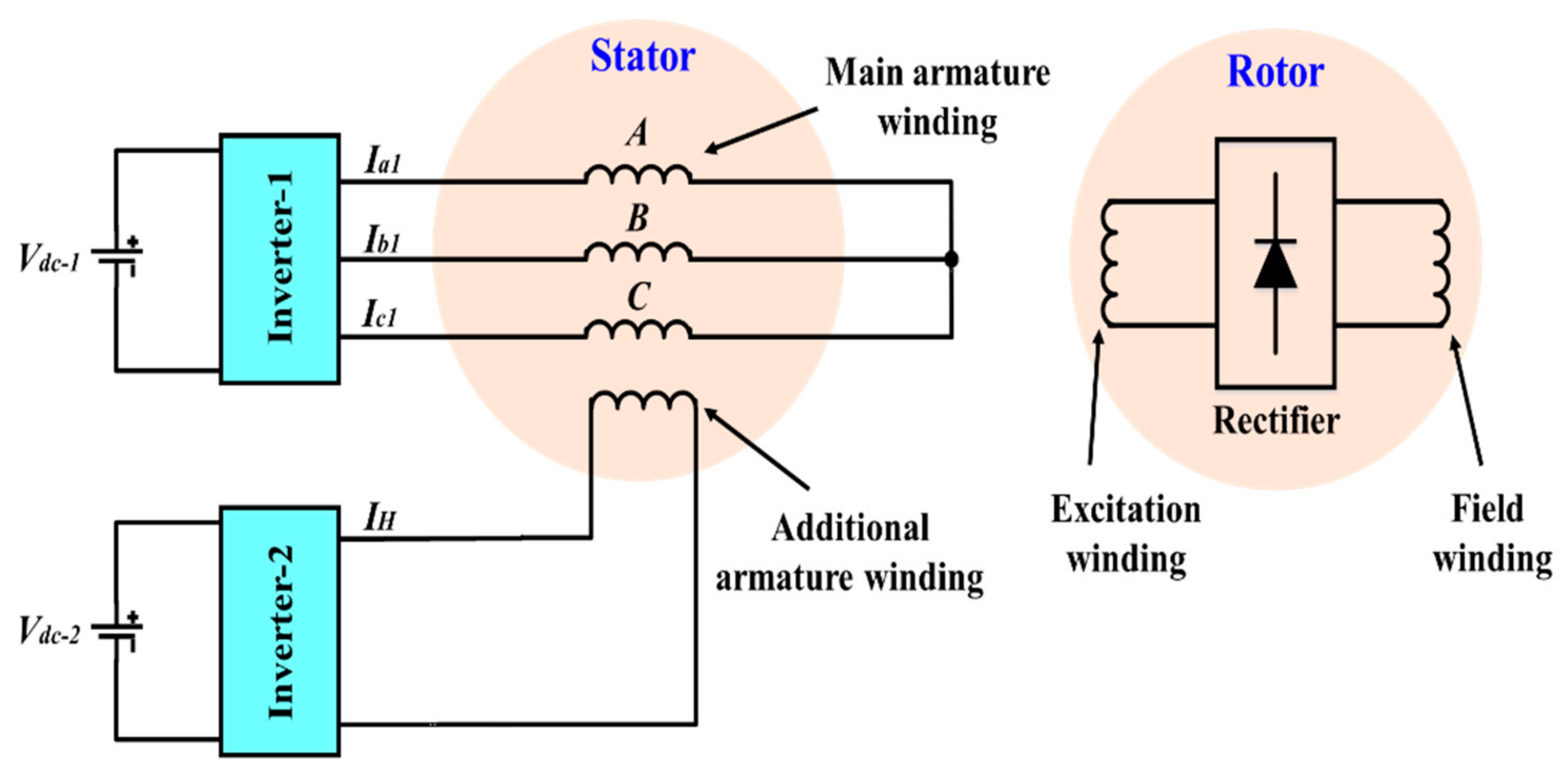
2.1. Proposed Topology

The proposed high-harmonic injection-based WFSM topology is presented in Figure 2. This topology employs two inverters, namely inverter-1 and inverter-2. Inverter-1 provides the regular three-phase input armature currents (Iabc1) to the armature winding (ABC) of the machine, whereas inverter-2 injects the single-phase high-harmonic current (IH) i.e., 6th harmonic current in this case, to the neutral-point of the Y-connected ABC winding. The input armature currents of inverter-1 are responsible for the fundamental-harmonic current of the armature winding that produces the fundamental MMF in the air gap. However, the single-phase 6th harmonic input current of inverter-2 is responsible for generating a high-harmonic current component of the armature winding. This current develops the high-harmonic MMF in the air gap. Although the fundamental and high-harmonic MMF components are produced by the same armature winding, the difference in their frequencies makes them uncoupled. On the rotor side, the rotor has two windings, namely excitation winding and field winding. Both windings are electrically connected by an uncontrolled rectifier. The fundamental MMF component produces the main armature magnetic field, whereas the high-harmonic MMF component induces the harmonic current in the rotor excitation winding. The induced harmonic current is rectified to inject DC to the field winding of the rotor to produce the rotor main field. The produced rotor field interacts with the equal number of stator poles to produce torque. A 4-pole 24-slot (4p24s) machine is utilized to validate the operation of the proposed high-harmonic injection-based WFSM topology. This machine is adopted from [16]. The structure of the employed machine along with its armature and rotor winding configurations are presented in Figure 3. As seen in the figure, the stator core is equipped with 4-pole, 24-slot, double-layered armature winding whereas the rotor is fitted with 4 rotor main teeth and 8 rotor sub-teeth to accommodate the excitation and field windings. The parameters of the armature winding used for the employed machine are presented in Table 1, which shows that the winding factor of the winding is 0.933. The winding factor and the three-phase MMF for the different harmonic numbers generated for armature winding used for the employed machine are presented in Figure 4a,b, respectively. The winding configuration used for the armature of the machine is chosen from the various options available on online tool named as Emetor-Electric motor winding calculator [21].

2.2. Mathematical Modelling

In order to explain the operation of the proposed high-harmonic injection-based field excitation scheme for the brushless operation of WFSMs, a mathematical model is presented in this sub-section.
For the typical WFSM topology employing 3rd harmonic injection-based field excitation scheme [12], the magnetomotive force (MMF) for each phase is expressed as:
M M F A = i A N φ 1 ( sin θ s + 1 3 sin 3 θ s ) M M F B = i B N φ 1 sin ( θ s 2 π 3 ) + 1 3 sin 3 θ s M M F C = i C N φ 1 sin ( θ s + 2 π 3 ) + 1 3 sin 3 θ s
where,
N φ 1 = 2 π ( p e r   p h a s e   n u m b e r   o f   t u r n s )
θs = electrical angle (spatial), and
ω = angular frequency (electrical).
The armature winding currents can be expressed as:
i A = I 1 sin ( ω t ) + I H i B = I 1 sin ( ω t 2 π 3 ) + I H i C = I 1 sin ( ω t + 2 π 3 ) + I H
where I1 is the fundamental and IH is the supplied single-phase harmonic current into the armature winding.
When you bring Equation (2) to Equation (1), and add the MMF of three-phase armature windings A, B, and C, the net MMF of the armature winding is expressed as:
M M F A B C ( θ s , i ) = M M F A + M M F B + M M F C
M M F A B C ( θ s , i ) = N φ 1 sin ( θ s ) + 1 3 sin 3 θ s I 1 sin ( ω t ) + I H + N φ 1 sin ( θ s 2 π 3 ) + 1 3 sin 3 θ s I 1 sin ( ω t 2 π 3 ) + I H + N φ 1 sin ( θ s + 2 π 3 ) + 1 3 sin 3 θ s I 1 sin ( ω t + 2 π 3 ) + I H
M M F A B C ( θ s , i ) = N φ 1 I 1 sin ( ω t ) sin ( θ s ) + sin ( ω t 2 π 3 ) sin ( θ s 2 π 3 ) + sin ( ω t + 2 π 3 ) sin ( θ s + 2 π 3 ) + I H sin 3 θ s
M M F A B C ( θ s , i ) = 3 2 I 1 N φ 1 cos ( ω t θ s ) + I H N φ 1 sin 3 θ s
Equation (6) gives the net MMF produced in the air gap, which consists of two parts: (1) the fundamental MMF component, which produces the main armature field of rotating nature, and (2) spatial-location-fixed MMF component that develops a harmonic field in the air gap. This MMF component is utilized by the injected single-phase harmonic current. Since the main armature and the harmonic fields are produced by the currents having different frequencies, both the fields are not coupled.
Assuming that θ0 is the rotor excitation winding initial position angle, the spatial position of the excitation winding can be calculated as under:
θ s = ω t + θ 0
The generated flux of each winding pole will be:
ψ E = n E P g N φ 1 3 2 I 1 cos ( ω t θ s ) + I H sin 3 θ s ψ E = n E P g N φ 1 3 2 I 1 cos θ 0 + I H sin ( 3 ω t + 3 θ 0 )
where nE is the rotor excitation winding number of turns, and Pg is the air gap permeance.
When IH is the 3rd harmonic current, as in the case of [12], we have:
I H = I 3 sin 3 ( ω t )
and the magnitude of the induced EMF in the rotor excitation winding can be calculated as [22,23]:
e E = 6 d ψ E d t e E = 6 n E P g N φ 1 0 + 3 I 3 ω cos 3 ( ω t ) sin ( 3 ω t + 3 θ 0 ) e E = 18 n E P g N φ 1 I 3 ω sin ( 6 ω t + 3 θ 0 )
As the proposed high-harmonic field excitation scheme is based on the injection of single-phase 6th harmonic current, IH in this case will become:
I H = I 3 sin 6 ( ω t )
and the magnitude of the induced EMF in the rotor excitation winding for the proposed high-harmonic injection-based field excitation scheme can be calculated as:
e E = 6 d ψ E d t e E = 6 n E P g N φ 1 0 + 6 I 3 ω cos 6 ( ω t ) sin ( 3 ω t + 3 θ 0 ) + 3 I 3 ω sin 6 ( ω t ) cos ( 3 ω t + 3 θ 0 )
e E = 3 n E P g N φ 1 I 3 ω 9 sin ( 9 ω t + 3 θ 0 ) 3 sin 3 ( ω t 3 θ 0 )
The induced EMF in the rotor excitation winding is rectified by an uncontrolled rectifier in order to inject DC to the field winding of the rotor to create the main rotor field. This field, when interacting with the 4-pole armature field, generates torque and archives brushless operation for WFSM.

3. Electromagnetic Analysis

To support the presented theory and to attain the electromagnetic performance of the proposed high-harmonic injection-based WFSM topology, a finite element method (FEM) is utilized in order to carry out a finite element analysis (FEA) in JMAG-Designer ver. 19.1. For the comparative performance analysis, typical brushless WFSM topology based on a 3rd harmonic injection field excitation scheme (as presented in Figure 1) is also implemented. Both topologies are investigated under the same loading conditions and for the same machine (as presented in Figure 3). The parameters of this machine are presented in Table 2. A slide mesh is generated to carry out the FEA. 50H1300 material manufactured by NIPPON STEEL is used for the stator and rotor cores. The FEA parameters along with the attributes associated with the generated mesh are presented in Table 3.

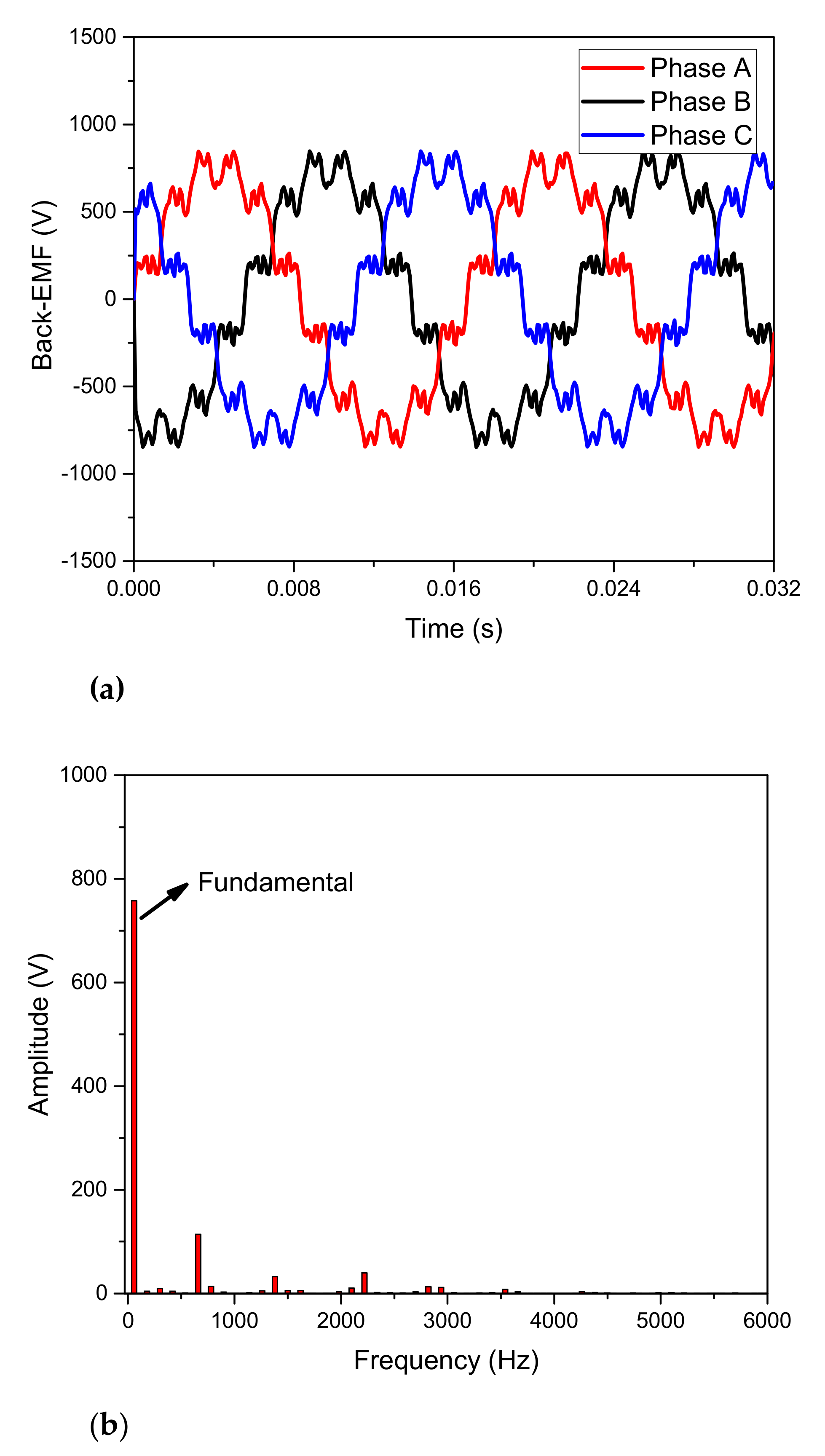
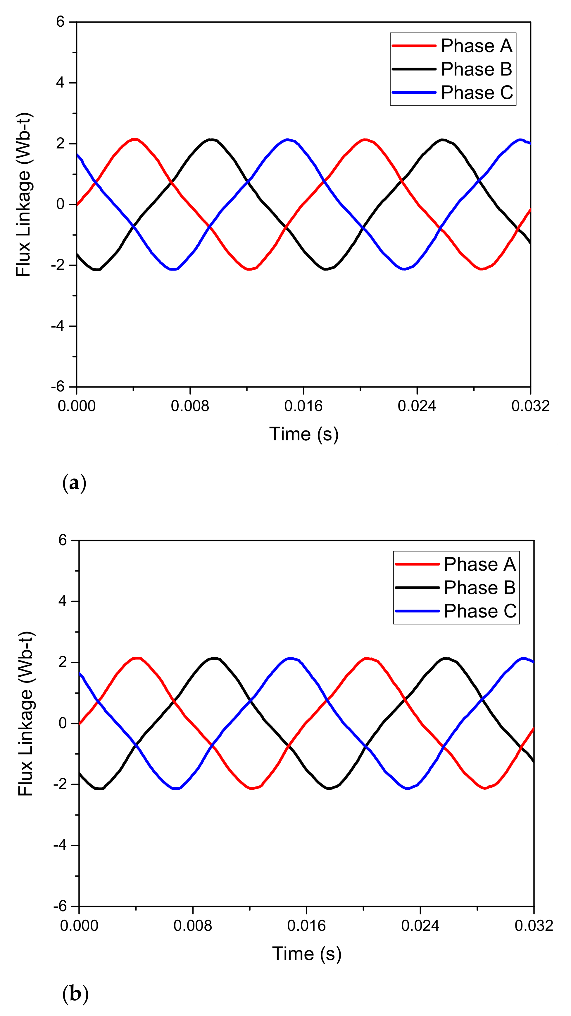
3.1. No-Load Analysis

To examine the no-load operation of the machine used for the validation of 3rd and 6th harmonic injection-based brushless WFSM topologies, no-load analysis is carried out in JMAG-Designer ver. 19.1. A field current of 2 A is directly supplied to the rotor field winding in order to generate the main rotor field. The rotor of the machine is rotated at 1800 rpm, as in the previous case. The magnetic flux density plot of the machine under such a condition is shown in Figure 5. This flux density plot shows that the operation of the machine is under a saturation level of 1.98 T. A back-EMF of 546.30 Vrms is generated. The generated back-EMF of the machine is shown in Figure 6a; however, the FFT plot of this back-EMF is presented in Figure 6b to show its harmonic contents. The peak-to-peak cogging torque of the employed machine is 1.68 Nm. The generated cogging torque is shown in Figure 7.

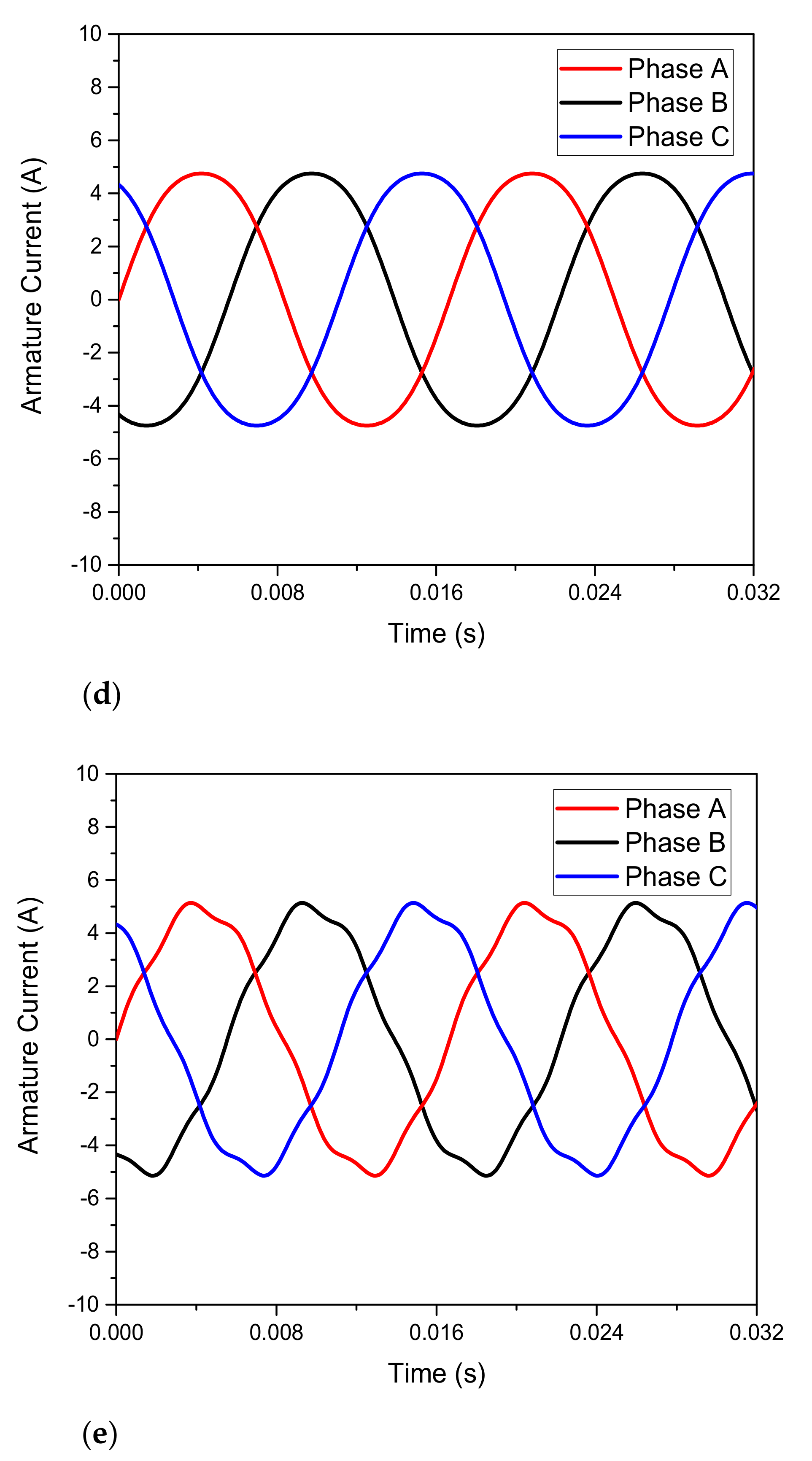
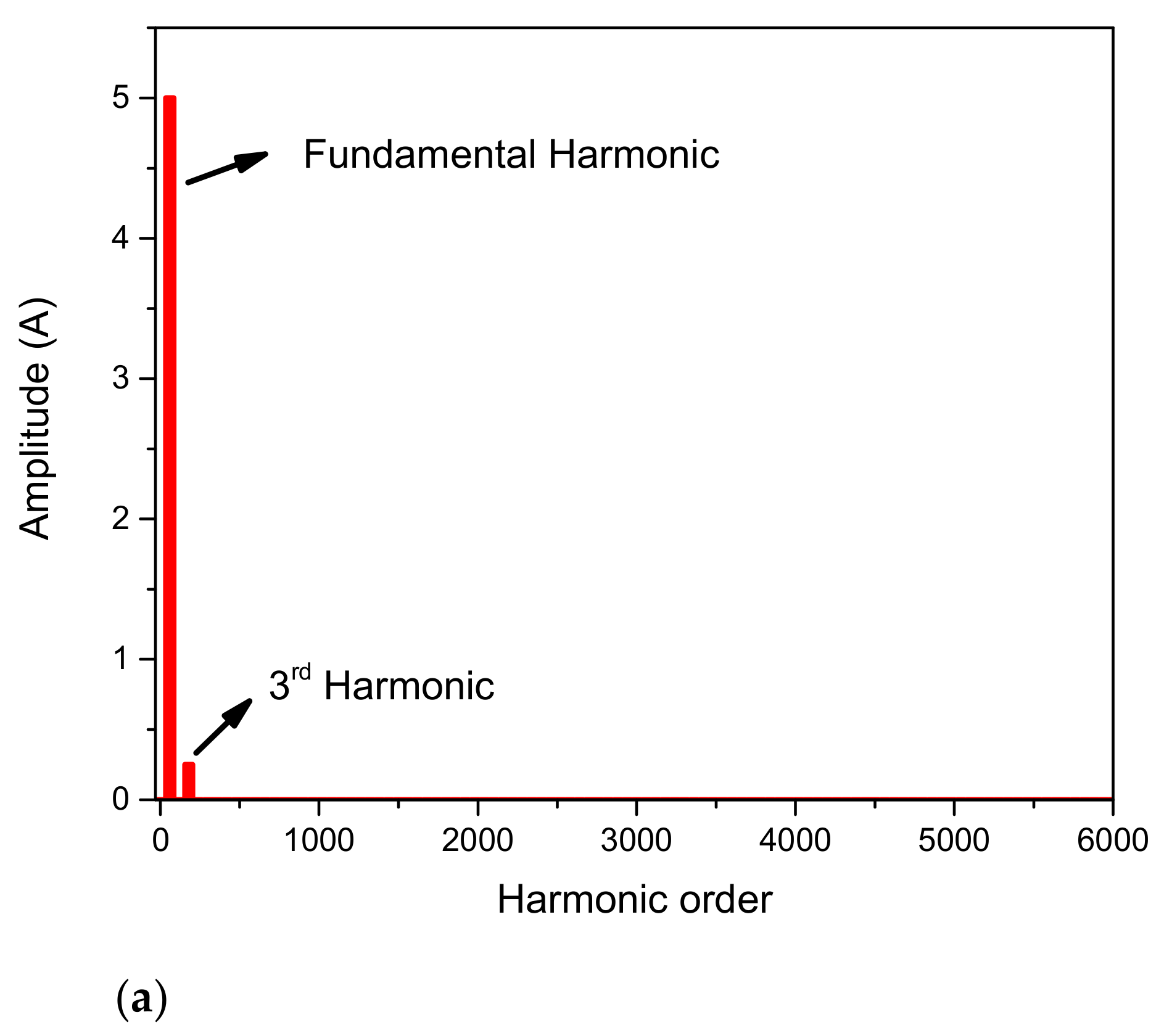
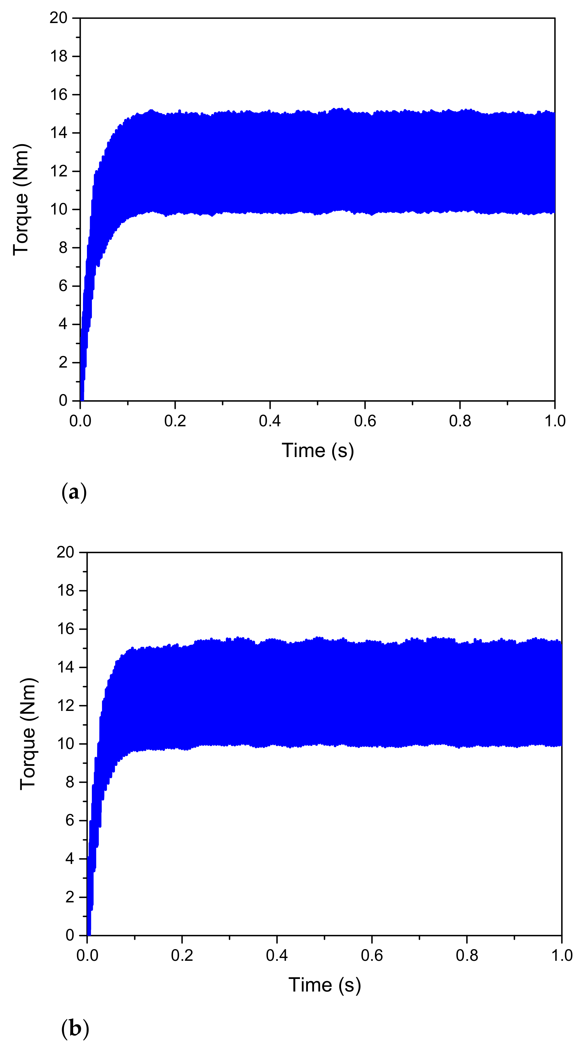
3.2. Full-Load Analysis

The three-phase input armature current of inverter-1 (Iabc1) for the 3rd and 6th harmonic injection-based brushless WFSM topologies is 5 A (peak) at a 60 Hz frequency. This current is presented in Figure 8a. In the case of the 3rd harmonic injection-based WFSM topology, the magnitude of the single-phase input armature current for inverter-2 is 1 A (peak) at a 180 Hz frequency, whereas it is 1 A (peak) at a 360 Hz frequency in the case of the proposed high-harmonic injection-based WFSM topology, as presented in Figure 8b,c, respectively. Figure 8d,e show the three-phase armature currents flowing across A, B, and C windings employing the 3rd and 6th harmonic injection-based brushless WFSM topologies. Fast Fourier transform (FFT) plots for phase A of the armature currents are produced to show the amplitude of the fundamental and harmonic current components for the 3rd and 6th harmonic injection-based WFSM topologies. These graphs are presented in Figure 9a,b, respectively.
The shaft of both machines is rotated at a speed of 1800 rpm, whereas the simulations are performed for 1 s. The flux linkages of the machine using the conventional and proposed WFSM topologies are presented in Figure 10a,b, respectively. Figure 11a,b show the magnetic field density plot of the analyzed machines employing the 3rd and 6th harmonic injection-based brushless WFSM topologies, respectively. These figures show that the operation of the investigated machines is under a saturation level of 2.24 T, and none of its parts become saturated during the operation. The rotor harmonic and field currents for the 3rd and 6th harmonic injection-based brushless WFSM topologies are presented in Figure 12a,b, respectively. As seen in the figures, the magnitude of the average field current for the brushless WFSM topology based on the 3rd harmonic field excitation scheme is around 2.007 A, whereas, for the proposed high-harmonic injection-based WFSM topology its magnitude is 2.08 A, which is 3.63% higher than the 3rd harmonic injection-based topology. Figure 13a,b show the output torque of the analyzed machines. The comparative performance analysis of the 3rd and 6th harmonic injection-based brushless WFSM topologies is presented in Table 4.

4. Conclusions

A high-harmonic injection-based field excitation scheme for the brushless operation of WFSMs has been discussed in this paper. This scheme utilized two inverters. One inverter provided the regular three-phase current, while the second inverter injected the single-phase 6th harmonic current to the neutral-point of the Y-connected armature winding. The regular three-phase current was used to produce the main armature field, whereas the single-phase 6th harmonic induced the harmonic current in the rotor excitation winding. The induced harmonic current was used to supply DC to the field winding of the rotor after rectification, in order to attain a brushless operation.
A four-pole, 24-slot machine was utilized to validate the operation of the proposed scheme and attain its electromagnetic performance by FEA. The proposed high-harmonic injection-based field excitation scheme attains a better performance for the output average torque, maximum torque, and efficiency. However, the torque ripple of the proposed scheme is 0.5% higher than the typical brushless WFSM topology, based on the 3rd harmonic field excitation scheme.

Author Contributions

Conceptualization, S.S.H.B. and F.H.M.; software, S.S.H.B. and I.S.; formal analysis, S.S.H.B. and Q.A.; writing—original draft preparation, S.S.H.B.; funding acquisition, J.-S.R. All authors have read and agreed to the published version of the manuscript.

Funding

This work was supported in part by the Brain Pool (BP) Program funded by the Ministry of Science and ICT through the National Research Foundation of Korea under Grant 2019H1D3A1A01102988, and in part by the Basic Science Research Program through the National Research Foundation of Korea funded by the Ministry of Education under Grant 2016R1D1A1B01008058.

Conflicts of Interest

The authors declare no conflict of interest.

References

  1. Sun, L.; Gao, X.; Yao, F.; An, Q.; Lipo, T. A new type of harmonic current excited brushless synchronous machine based on an open winding pattern. In Proceedings of the 2014 IEEE Energy Conversion Congress and Exposition (ECCE), Pittsburgh, PA, USA, 14–18 September 2014; pp. 2366–2373. [Google Scholar]
  2. Yao, F.; An, Q.; Sun, L.; Lipo, T.A. Performance Investigation of a Brushless Synchronous Machine with Additional Harmonic Field Windings. IEEE Trans. Ind. Electron. 2016, 63, 6756–6766. [Google Scholar] [CrossRef]
  3. Inoue, K.; Yamashita, H.; Nakamae, E.; Fujikawa, T. A brushless self-exciting three-phase synchronous generator utilizing the 5th-space harmonic component of magneto motive force through armature currents. IEEE Trans. Energy Convers. 1992, 7, 517–524. [Google Scholar] [CrossRef]
  4. Yao, F.; An, Q.; Sun, L.; Illindala, M.S.; Lipo, T.A. Optimization design of stator excitation windings in brushless synchronous machine excited with double-harmonic-windings. In Proceedings of the 2017 International Energy and Sustainability Conference (IESC), Farmingdale, NY, USA, 19–20 October 2017; pp. 1–6. [Google Scholar]
  5. Ayub, M.; Hussain, A.; Jawad, G.; Kwon, B. Brushless Operation of a Wound-Field Synchronous Machine Using a Novel Winding Scheme. IEEE Trans. Magn. 2019, 55, 8201104. [Google Scholar] [CrossRef]
  6. Ali, Q.; Lipo, T.A.; Kwon, B.-I. Design and analysis of a novel brushless wound rotor synchronous machine. IEEE Trans. Magn. 2015, 51. [Google Scholar] [CrossRef]
  7. Hussain, A.; Kwon, B.-I. A new brushless wound rotor synchronous machine using a special stator winding arrangement. Electr. Eng. 2018, 100, 1797–1804. [Google Scholar] [CrossRef]
  8. Ali, Q.; Bukhari, S.S.H.; Atiq, S. Variable-speed, sub-harmonically excited BL-WRSM avoiding unbalanced radial force. Electr. Eng. 2019, 101, 251–257. [Google Scholar] [CrossRef]
  9. Ayub, M.; Atiq, S.; Sirewal, G.J.; Kwon, B. Fault-Tolerant Operation of Wound Field Synchronous Machine Using Coil Switching. IEEE Access 2019, 7, 67130–67138. [Google Scholar] [CrossRef]
  10. Ayub, M.; Jawad, G.; Kwon, B. Consequent-Pole Hybrid Excitation Brushless Wound Field Synchronous Machine with Fractional Slot Concentrated Winding. IEEE Trans. Magn. 2019, 55, 8203805. [Google Scholar] [CrossRef]
  11. Khan, S.; Bukhari, S.S.H.; Ro, J. Design and Analysis of a 4-kW Two-Stack Coreless Axial Flux Permanent Magnet Synchronous Machine for Low-Speed Applications. IEEE Access 2019, 7, 173848–173854. [Google Scholar] [CrossRef]
  12. Bukhari, S.S.H.; Sirewal, G.J.; Chachar, F.A.; Ro, J.-S. Brushless Field Excitation Scheme for Wound Field Synchronous Machines. Appl. Sci. 2020, 10, 5866. [Google Scholar] [CrossRef]
  13. Bukhari, S.S.H.; Sirewal, G.J.; Chachar, F.A.; Ro, J.-S. Dual-Inverter-Controlled Brushless Operation of Wound Rotor Synchronous Machines Based on an Open-Winding Pattern. Energies 2020, 13, 2205. [Google Scholar] [CrossRef]
  14. Jawad, G.; Ali, Q.; Lipo, T.A.; Kwon, B.I. Novel brushless wound rotor synchronous machine with zero-sequence third-harmonic field excitation. IEEE Trans. Magn. 2016, 52, 8106104. [Google Scholar] [CrossRef]
  15. Bukhari, S.S.H.; Sirewal, G.J.; Ro, J.-S. A New Small-Scale Self-Excited Wound Rotor Synchronous Motor Topology. IEEE Trans. Magn. 2021, 57, 8200205. [Google Scholar] [CrossRef]
  16. Bukhari, S.S.H.; Ahmad, H.; Sirewal, G.J.; Ro, J.-S. Simplified Brushless Wound Field Synchronous Machine Topology Based on a Three-phase Rectifier. IEEE Access 2021, 9, 8637–8648. [Google Scholar] [CrossRef]
  17. Bukhari, S.S.H.; Sirewal, G.J.; Madanzadeh, S.; Ro, J.-S. Cost-Effective Single-Inverter-Controlled Brushless Scheme for Wound Rotor Synchronous Machines. IEEE Access 2020, 8, 204804–204815. [Google Scholar] [CrossRef]
  18. Ayub, M.; Bukhari, S.S.H.; Sirewal, G.J.; Arif, A.; Kwon, B.-I. Utilization of Reluctance Torque for Improvement of the Starting and Average Torques of a Brushless Wound Field Synchronous Machine. Electr. Eng. 2021, 103. [Google Scholar] [CrossRef]
  19. Ayub, M.; Sirewal, G.J.; Bukhari, S.S.H.; Kwon, B.-I. Brushless wound rotor synchronous machine with third-harmonic field excitation. Electr. Eng. 2020, 102, 259–265. [Google Scholar] [CrossRef]
  20. Ayub, M.; Bukhari, S.S.H.; Kwon, B.-I. Brushless Wound-Field Synchronous Machine with Third-Harmonic Field Excitation using a Single Inverter. Electr. Eng. 2019, 101, 165–173. [Google Scholar] [CrossRef]
  21. Emetor, A.B. Electric Motor Winding Calculator. Available online: https://www.emetor.com/windings/ (accessed on 25 June 2021).
  22. Yao, F.; An, Q.; Gao, X.; Sun, L.; Lipo, T.A. Principle of operation and performance of a synchronous machine employing a new harmonic excitation scheme. IEEE Trans. Ind. Appl. 2015, 51, 3890–3898. [Google Scholar] [CrossRef]
  23. An, Q.; Gao, X.; Yao, F.; Sun, L.; Lipo, T. The structure optimization of novel harmonic current excited brushless synchronous machines based on open winding pattern. In Proceedings of the 2014 IEEE Energy Conversion Congress and Exposition (ECCE), Pittsburgh, PA, USA, 14–18 September 2014; pp. 1754–1761. [Google Scholar]
Figure 1. Typical 3rd harmonic injection-based brushless WFSM topology employing two dual-stator winding configurations.
Mathematics 09 01721 g001
Figure 2. Proposed brushless WFSM topology.
Mathematics 09 01721 g002
Figure 3. Two-dimensional machine layout and its winding configuration.
Mathematics 09 01721 g003
Figure 4. (a) Winding factor and (b) three-phase MMF for different harmonic numbers generated for the armature winding used for employed machine [21].
Mathematics 09 01721 g004
Figure 5. Magnetic flux density plot of the employed machine.
Mathematics 09 01721 g005
Figure 6. (a) Back-EMF of the employed machine, and (b) its FFT plot.
Mathematics 09 01721 g006
Figure 7. Cogging torque of the employed machine.
Mathematics 09 01721 g007
Figure 8. (a) Inverter-1 current, (b) inverter-2 current for the 3rd harmonic injection-based topology, (c) inverter-2 current for the 6th harmonic injection-based topology, (d) armature currents for the 3rd harmonic injection-based topology, and (e) armature currents for the 6th harmonic injection-based WFSM topology.
Mathematics 09 01721 g008aMathematics 09 01721 g008b
Figure 9. FFT plot of phase A of the armature currents for (a) typical brushless WFSM topology based on 3rd harmonic field excitation scheme, and (b) proposed high-harmonic injection-based WFSM topology.
Mathematics 09 01721 g009aMathematics 09 01721 g009b
Figure 10. Flux linkages for (a) 3rd harmonic injection-based, and (b) 6th harmonic injection-based WFSM topologies.
Mathematics 09 01721 g010
Figure 11. Magnetic flux density graph for (a) 3rd harmonic injection-based, and (b) 6th harmonic injection-based WFSM topologies.
Mathematics 09 01721 g011
Figure 12. Rotor currents for (a) 3rd harmonic injection-based, and (b) 6th harmonic injection-based WFSM topologies.
Mathematics 09 01721 g012aMathematics 09 01721 g012b
Figure 13. Output torque for (a) 3rd harmonic injection-based, and (b) 6th harmonic injection-based WFSM topologies.
Mathematics 09 01721 g013
Table 1. Winding parameters for the employed machine.
ParameterValue
Number of poles/slots/layers4/24/2
Coil span5 slots
Pole pitch6 slots
Periodicities2, 4
Winding factor0.933
Table 2. Machine specifications.
ParameterValue
Rated power3 kW
Machine poles/Stator slots4/24
Rated speed1800 rpm
Frequency60 Hz
Stator outer/inner diameter130/80 mm
Air gap0.5 mm
Rotor diameter79 mm
Rotor main/sub-teeth4/8
Exciter/Field winding number of turns25/250
Armature winding number of turns100
Stack length90 mm
Table 3. FEA parameters.
AttributeValue
Boundry conditions195 mm
Number of divisions21,600
Time interval/1 step92.5 μs
Number of steps21,601
Number of elements (for Mesh)5508
Number of nodes (for Mesh)4024
Radial divisions (for Mesh)7
Circumferential divisions (for Mesh)360
Table 4. Comparative performance analysis.
Attribute3rd Harmonic Injection-Based Topology6th Harmonic Injection-Based Topology
Average output torque12.4814 Nm12.8048 Nm
Maximum torque15.1361 Nm15.3927 Nm
Torque ripple42%42.5%
Efficiency82.91%85.095%
Publisher’s Note: MDPI stays neutral with regard to jurisdictional claims in published maps and institutional affiliations.

