Article

Complementary Airflow Control of Oscillating Water Columns for Floating Offshore Wind Turbine Stabilization

1
Automatic Control Group—ACG, Institute of Research and Development of Processes—IIDP, Department of Automatic Control and Systems Engineering, Faculty of Engineering of Bilbao, University of the Basque Country—UPV/EHU, Po Rafael Moreno no3, 48013 Bilbao, Spain
2
Automatic Control Group—ACG, Institute of Research and Development of Processes—IIDP, Department of Electricity and Electronics, Faculty of Science and Technology, University of the Basque Country—UPV/EHU, Bo Sarriena s/n, 48080 Leioa, Spain
*
Author to whom correspondence should be addressed.
Mathematics 2021, 9(12), 1364; https://doi.org/10.3390/math9121364
Submission received: 14 May 2021 / Revised: 8 June 2021 / Accepted: 11 June 2021 / Published: 12 June 2021
(This article belongs to the Special Issue Mathematical Methods in Renewable Energies)

Abstract

:
The implementation and integration of new methods and control techniques to floating offshore wind turbines (FOWTs) have the potential to significantly improve its structural response. This paper discusses the idea of integrating oscillating water columns (OWCs) into the barge platform of the FOWT to transform it into a multi-purpose platform for harnessing both wind and wave energies. Moreover, the OWCs will be operated in order to help stabilize the FOWT platform by means of an airflow control strategy used to reduce the platform pitch and tower top fore-aft displacement. This objective is achieved by a proposed complementary airflow control strategy to control the valves within the OWCs. The comparative study between a standard FOWT and the proposed OWC-based FOWT shows an improvement in the platform’s stability.

1. Introduction

Winds and breezes occur between land and sea due to differential heating and pressure and, therefore, it is best to install wind turbines in coastal areas. However, due to the rarity of coastal lands and coastal residential concentrations, offshore wind turbines are proving to be the best alternative. Moreover, offshore wind resources are known to be of higher quality than those on land [1]. Hence global wind power development has been progressively switching to being offshore. Nearshore wind farms have been developed in past years but were criticized for visual and noise pollution [2], and their foundations are relatively big, complex, and costly [3]. On the other hand, with no space restrictions and stronger and steadier wind resources, deep-sea wind farms have greater potential to be exploited. Wind- and wave-induced loads on the FOWT structure increase stress on the structure, the possibility of damage and failures, and the cost of maintenance while decreasing its efficiency and lifespan. Many approaches have been developed for load mitigation and can be classified into two categories.
The first method uses rotor thrust as a restoring moment to reduce platform and tower pitch. This approach is achieved by regulating the blade pitch angle to change rotor thrust. J. Jonkman et al. carried out extensive research on developing the FAST (fatigue, aerodynamics, structures, and turbulence) simulator and designing a baseline collective blade pitch controller for three main floating wind turbines using a gain-scheduled proportional-integral approach [4,5]. Reducing the controller gain reduces the blade pitch angle, thus increasing the rotor thrust and platform pitch damping. M.A. Lackner et al. [6] developed an approach that regulates the blade pitch angle by changing the reference input, which is the rated rotor speed. Directly changing the expected rotor speed helps generate extra restoring moment. A. Staino et al. [7] proposed an innovative dual control strategy combining passive pitch control and active tendons inside the hollow structure of the blades to alleviate aerodynamic loads on blades as a solution to the disadvantages of using active pitch control. All these blade pitch control methods have shown efficiency in reducing part of the wave-wind-induced loads on floating wind turbines. However, they present two drawbacks. The first drawback is that it requires more blade pitch usage, higher power fluctuation, and increased loads at blade roots, which reduces the turbine’s lifespan. The second drawback is that for some FOWTs, the structure still suffers from relatively significant and intolerable loads, even after implementing the pitch control [8].
The second method for load reduction for floating wind turbines is using passive or active structural control. M.A. Lackner et al. [6] developed FAST-SC to consider structural control design in FOWTs based on FAST using a passive tuned mass damper (TMD) installed in the nacelle. This is achieved by adding two DOFs for the TMD in the kinetic equations and the TMD for a barge-type FOWT is optimized in [9]. Later, Y. Si et al. [10] used passive TMD in the nacelle for a spar-type FOWT. N. Luo et al. [11] considered the FOWT as a lump mass and used a tuned liquid column damper (TLCD) to suppress its surge motion. G.M. Stewart et al. [12] developed a 3-DOF dynamic model for three kinds of FOWT, namely the barge, spar, and tension-leg platform (TLP), based on Newton’s second law of motion by using a TMD in the nacelle and platform for load mitigation. E.M. He et al. implemented a 3-DOF dynamic model of the barge-type FOWT in [13] based on FAST-SC and Euler–Lagrange equations and optimized the TMD mass installed in nacelle and investigated its control effect. Y. Hu et al. [14] investigated the application of inerters to a barge-type FOWT to mitigate the loads induced by winds and waves. Structural control may be further improved by using active control which proven to yield better results than the passive ones. In [15], a structural control design based on a hybrid mass damper (HMD) of a barge-type FOWT was achieved by solving an H∞ loop shaping problem, and it is conditionally stable and provides effective damping performance when properly tuned. Y.L. Si et al. [16] developed a H2/H∞ HMD structural controller for load mitigation of a spar-type FOWT using a gain scheduling technique. Y. Hu et al. [17] designed an active structural control with a stroke-limited HMD using LQR controllers. Y. Zhang et al. [18] proposed a disturbance observer-based adaptive hierarchical sliding mode control of an underactuated FOWT with a TMD for vibration suppression.
Lately, investigations and developments are pushing toward the use of offshore wind turbines as multipurpose platforms for better use, efficiency, and cost reduction. From an industry point of view, a hybrid wind–wave energy converter would harvest both energies using the same platform, the same mooring system, and the same site, which means more sustainable energy in less occupied space. Moreover, the extracted wave energy can be used to compensate for wind energy in the event of a power shortage. Finally, successfully reducing the undesired motion using the OWC would help increase the FOWT lifespan and reduce the maintenance costs. From a research point of view, the hybrid platform would serve as a test-bench for researchers to investigate the use of other types of wave energy converters (WEC) as active structural controls to stabilize the FOWT platform. Moreover, it would help understand and study the correlation between ocean winds and waves and how they break up upon entering an offshore wind farm due to the effects of the wake phenomenon.
The most studied platform is wind–wave platforms that combine wind turbines and WEC to harness the wave and wind energies [19,20,21]. The use of the OWC with a floating offshore wind turbine has been proposed and shown promising results. J.M. Kluger et al. [22] investigated the use of WEC array with the a spar-type FOWT from National Renewable Energy Laboratory (NREL) called OC3-Hywind FOWT. Later, A. Slocum et al. [23] discussed the use of an external and internal heave WEC on the same FOWT. M. Kamarlouei et al. [24] concluded that installation of a WEC array may decrease the FOWT’s platform motions in heave and pitch. However, the introduced approaches have not used OWCs in barge-based FOWT platforms.
Although OWCs have been applied in different FOWTs, especially spar-type ones, to decrease the motions, the application of OWCs in barge-based FOWTs for stabilization has not yet been reported. This work aims to combine a floating offshore wind turbine with an oscillating water column to harness both wave and wind energies and to study the stabilization of the FOWT using the OWCs. The considered FOWT is the NREL 5 MW wind turbine mounted on the ITI Energy barge platform. The ITI Energy barge is a concept that was developed by the Department of Naval Architecture and Marine Engineering at the Universities of Glasgow and Strathclyde through a contract with ITI Energy (please see [25] for a detailed explanation about this subject). The idea is to integrate OWCs within the ITI Energy barge to help reduce the undesired motions of the platform. This may be achieved by controlling the air valves of every OWC using an airflow control strategy [26,27,28] to adjust the airflow and pressure inside the capture chambers. The novel aspects of the presented work are as follows:
  • Novel multi-purpose FOWT structure harvesting both wind and wave energy.
  • Mathematical dynamic FOWT model incorporating OWC pressure and forces.
  • Novel active structural control using the OWC devices.
  • Complementary airflow control between the OWC devices for platform pitch and fore-aft displacement reduction.
The rest of the paper is organized as follows: Section 2 describes the OWC-based FOWT model and its equations. Section 3 presents the proposed complementary airflow control implemented to regulate the airflow and pressure in the chambers for FOWT stabilization. Two comparative studies of the FOWT between the standard ITI Energy barge and the OWC-based barge are presented in Section 4. Finally, Section 5 ends the paper with some concluding remarks.

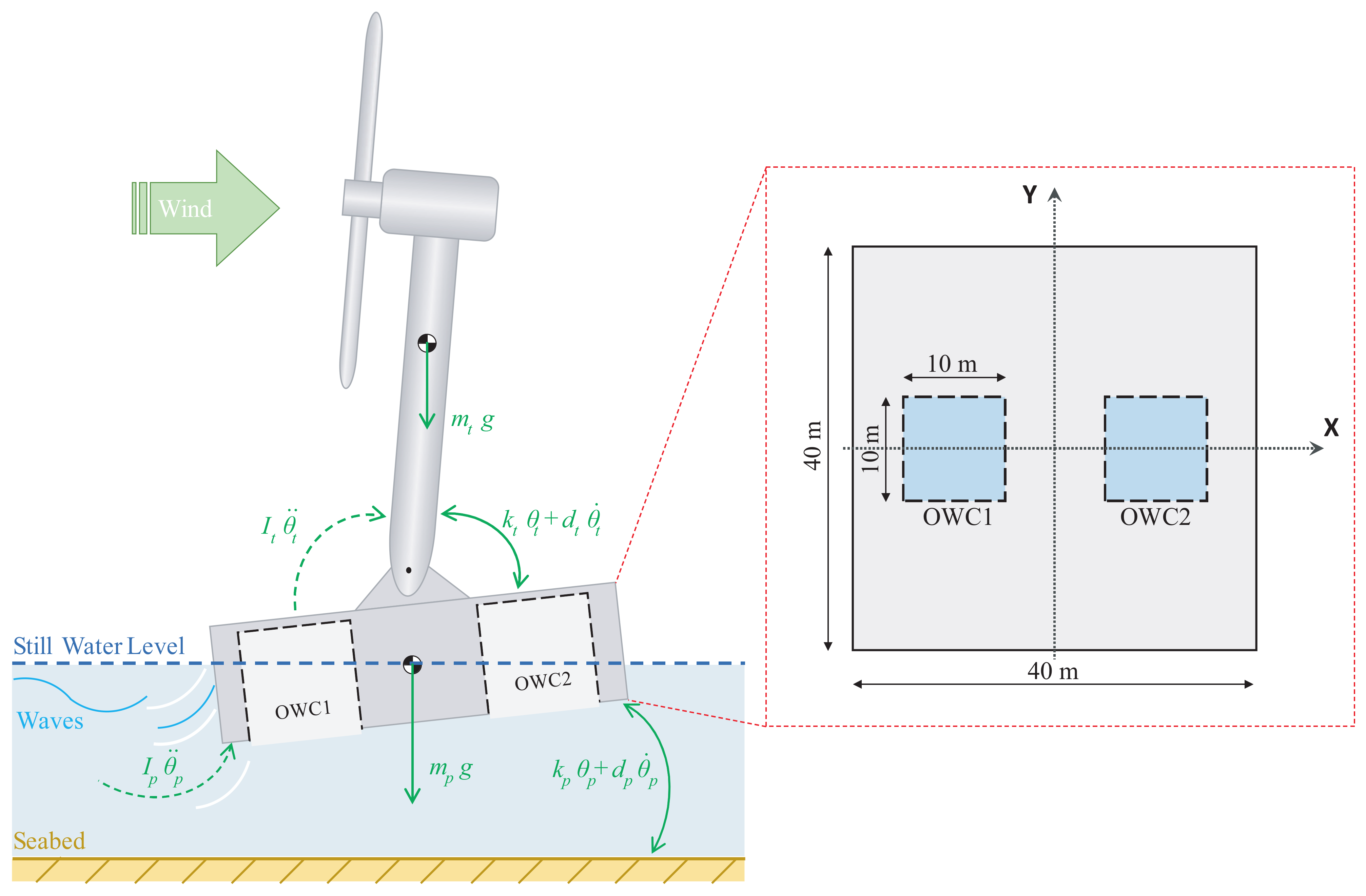
2. OWC-Based FOWT Platform Model

The work carried out in this paper revolves around the floating offshore wind turbine which is illustrated in Figure 1. The FOWT under study is the NREL offshore 5 MW baseline wind turbine and the adopted barge model is the ITI Energy barge, a simple rectangular platform which is commonly used for research in the literature for load analysis and conception verification of offshore wind turbines.
The turbine is a three-bladed, upwind, variable speed, pitch controlled turbine with a 126 m rotor diameter. The blades drive a generator installed at the top of the tower in the nacelle at a 90 m hub height. The wind turbine is mounted on a ballasted barge platform moored by catenary lines to reduce drifting and improve stability. Detailed specifications of the 5 MW wind turbine and the ITI barge platform can be found in [4], of which some basic parameters are provided in Table 1.
In a typical onshore wind turbine, the tower top displacements (fore-aft and side-to-side) can be met due to bending moment endured by the tower. However, the rotational modes (pitch, roll, and yaw) and translational modes (surge, sway, and heave) of the barge platform are not met in an onshore wind turbine. On the other hand, floating offshore wind turbines (FOWTs) experience tower top displacements, rotational modes, and translational modes of the platform, adding more undesired vibration and instability to the system. According to many studies, even though the floating platforms have a large surging motion, it is well known that the barge pitching motion that contributes the most to the tower bending [29], and since the tower bending caused by barge pitching around the Y-axis affects the tower top displacement in the X-axis direction, the fore-aft displacement is also very important in FOWT stability. Hence, we only enable the pitching mode but disable the translational surging one. This approach has been shown to be sufficiently effective for structural vibration control of FOWTs [9,12,16]. Therefore, the model of the considered system focuses on two modes of the full-DOF wind turbine, which are the platform pitch motion and the tower first fore-aft bending mode. Furthermore, the work in this paper focuses on the vibration dynamics of the FOWT that are more related with waves. Thus, the wind effect on the turbine were omitted in order to obtain a linear design model and design the adequate control.
Finally, the structural parameters used for this FOWT model are detailed in Table 2.

2.1. Dynamic Model of an OWC-Based FOWT

For the barge-type FOWT, the most significant DOFs affecting the tower loads of the wind turbine structure are the platform pitch motion and the tower first fore-aft bending mode [15,30]. Thus, these two DOFs are used in the design of the simplified reduced-order wind turbine model, and its scheme is shown in Figure 2, adopted from [12,17].
The tower of the wind turbine is assumed to be coupled to the barge platform by a rotary spring, representing the structural stiffness k t , and a damper representing structural damping d t . The mooring lines’ stiffnesses and hydrostatic restoring moments affecting the barge are represented by the spring constant k p , and the hydrodynamic damping effects on the barge, including viscous and wave radiation effects, are modeled by the damping coefficient d p as shown in Figure 2.
To help reduce the platform pitch and the tower first fore-aft bending mode, two OWCs have been adopted and integrated into the structure of the ITI Energy barge platform. Both OWCs are identical and have been placed on both sides of the tower (front and back) at an equal distance to maintain symmetry as shown in Figure 2. The parameters of both OWCs are detailed in Table 3.
The Euler–Lagrange equations of a non-conservative system with n generalized coordinates or DOFs are described by (1) and (2):
d d t L q ˙ i L q i = Q i i = 1 , 2 , , n
L = T V
where T and V are the total kinetic energy and total potential energy of the system, respectively. L is the Lagrange operator. Q i is the generalized non-potential force.
The total kinetic energy and total potential energy of the barge-type floating wind turbine can be expressed as:
T = 1 2 I t θ ˙ t 2 + 1 2 I p θ ˙ p 2
V = 1 2 k t θ t θ p 2 + 1 2 k p θ p 2 + m t g R t cos θ t m p g R p cos θ p
where k is the equivalent spring stiffness coefficient θ is the rotation angle from the vertical z-axis, I is the moment of inertia about the mass center. m is the mass, g is the gravitational acceleration and R is the distance from the mass center to the tower hinge. The subscripts p and t represent the platform and the tower, respectively.
The generalized non-potential forces consist of damping force and external wind and wave loads expressed as:
Q θ t = d t θ ˙ t θ ˙ p + M w i n d Q θ p = d p θ ˙ p + d t θ ˙ t θ ˙ p + M w a v e R o w c 1 f o w c 1 + R o w c 2 f o w c 2
where d is the equivalent damping coefficient, M w i n d and M w a v e are the bending moments caused by the external wind and wave loads acting on the tower base and the platform top, respectively. f o w c 1 and f o w c 2 are the forces induced by the pressures in the capture chambers of OWC1 and OWC2, respectively.
Substituting (3)–(5) into (1) and (2) and considering small angle approximations because none of the platforms exceed 10 degrees of pitch, even in the heaviest wind and wave loadings and assuming that both OWCs are at an equal distance from the tower hinge ( R O W C 1 = R O W C 2 = R O W C ), the contact nonlinear dynamic model of the barge floating wind turbine can be expressed as:
I p θ ¨ p k t θ t θ p + k p θ p + m p g R p θ p = d p θ ˙ p + d t θ ˙ t θ ˙ p + M w a v e R o w c ( f o w c 1 f o w c 2 ) I t θ ¨ t + k t θ t θ p m t g R t θ t = d t θ ˙ t θ ˙ p + M w i n d
Denoting the following inertia, damping, and stiffness matrices:
M = I p 0 0 I t , D = d p + d t d t d t d t , K = k p + k t + m p g R p k t k t k t m t g R t
then the equations of the system (6) may be written as:
M q ¨ + D q ˙ + K q = E M e x t + R F
where q = θ p θ t , M e x t = M w i n d M w a v e , F = f o w c 1 f o w c 2 0 , E = 0 1 1 0 , and R = R o w c 0 0 0 .
Using Equation (7), the plant may be described by the following state space model:
X ˙ m = A m X m + B m F + B e x t M e x t
where X m = q q ˙ , A m = 0 I M 1 K M 1 D , B m = 0 M 1 R , B e x t = 0 M 1 E .
Wind and wave interact with the FOWT structure in a complex aero-elastic and hydro-elastic way. Moreover, there exists inherent coupling between wind- and wave-induced structural responses [14]. In order to obtain a linear model, the wind and wave loads M w i n d and M w a v e were assumed to be linearly obtained by the hub height wind speed V w i n d ( t ) and the wave elevation Z ( t ) and, hence, M w i n d and M w a v e are represented by first-order dynamics as [14]:
M ˙ w i n d ( t ) = α w i n d M w i n d ( t ) + β w i n d V w i n d ( t )
M ˙ w a v e ( t ) = α w a v e M w a v e ( t ) + β w a v e Z ( t )
By introducing (9) and (10) into (8), the linear model becomes:
X ˙ = A X + B U + B w W
where X = X m M w i n d M w a v e , A = A m B e x t 0 α , B = B m 0 , B w = 0 β , U = F 0 , and W = V w i n d ( t ) Z ( t ) , α = α w i n d 0 0 α w a v e , β = β w i n d 0 0 β w a v e .
Finally, the platform pitch and tower fore-aft displacement are obtained from:
Y = C X
where Y = P i t c h F o r e a f t and C = 1 0 0 0 0 0 H T H T 0 0 0 0 .

2.2. Oscillating Water Columns Forces

Since ocean waves are larger than nearshore waves, it is possible to assume that waves are large enough to consider the oscillating water free-surface inside the OWC chambers as one rigid body heaving inside the column along the vertical axis. Hence, it is possible to assume that the internal free surface inside the OWC’s chamber behaves like a piston and the pressure is uniform according to the following assumptions:
  • The ocean waves are large enough to make the water free-surface inside the chambers oscillate as the same body (piston).
  • The water free-surface inside the chamber only oscillates along the chamber’s vertical axis.
  • The water free-surface is a rigid piston with a thickness that may be non-zero but the sum of the mass and added mass of the rigid piston is practically independent of its thickness.
The assumption is that the internal free surface inside the OWC’s chamber behaves like a piston and the pressure is uniform. Hence, the force maybe defined as [31,32]:
f O W C i = p i ( t ) S ( i = 1 , 2 )
where p i ( t ) is the chamber’s pressure and S is the chamber’s inner free surface which is the same for both OWCs. The subscript i = 1 , 2 is to refer to OWC1 or OWC2.
Considering the air as an ideal gas and the system is adiabatic and the transformations are slow enough to be reversible, the transformations may then be considered isentropic and the air density may be defined as:
ρ i ( t ) = ρ a p i ( t ) p a 1 γ
where p a and ρ a are the atmospheric pressure and density. γ is the air specific heat ratio.
By linearizing the isentropic relationship between density and pressure, we get:
ρ i ( t ) = ρ a p i ( t ) p a γ
ρ ˙ i ( t ) = ρ a p a γ p ˙ i ( t )
The mass flow rate inside the chambers can be defined as:
m ˙ i ( t ) = d d t ρ i ( t ) V O W C i ( t ) = ρ a V 0 p a γ p ˙ i ( t ) + ρ a V ˙ O W C i ( t )
where V 0 is the volume of air in the chamber in undisturbed conditions and V O W C ( t ) is the instantaneous air volume.
The oscillating air volume V O W C ( t ) depends on the OWC capture chambers geometry and is defined as:
V O W C i ( t ) = V 0 S Z i ( t )
where the chamber’s inner free surface is S= l c w c and Z i is the vertical displacement of the piston-like water, increasing in the upward direction.
Hence, the pressure within the chambers depend on the mass flow rate and the oscillating air volume:
p ˙ i ( t ) = p a γ ρ a V 0 m ˙ i ( t ) p a γ V 0 V ˙ i ( t )
Taking into consideration that the OWCs are using Wells turbine, the turbomachinery equations of the Wells turbine may be used [33,34]. The dimensionless flow coefficient of the the Wells turbine is defined as:
Φ = m ˙ ρ a ω r 3
where Φ is the flow coefficient. r and ω are the radius and rotational speed of the Wells turbine.
The flow coefficient of the Wells turbine can be expressed as the axial velocity of the air through the turbine by the tangential rotor velocity as:
Φ = v x r ω
where v x is the axial velocity of the air through the Wells turbine.
The volumetric flow rate Q is the volume of air that passes per unit time, may also be defined as a function of the axial velocity of the air through the turbine by:
Q = d V d t = a v x
where a is the Wells turbine’s cross-sectional area.
By substituting (20)–(22) in (19), we obtain the pressure as a function of the airflow speed as:
p ˙ i ( t ) = p a γ V 0 r 2 v x i ( t ) p a γ V 0 a v x i ( t ) ( i = 1 , 2 )

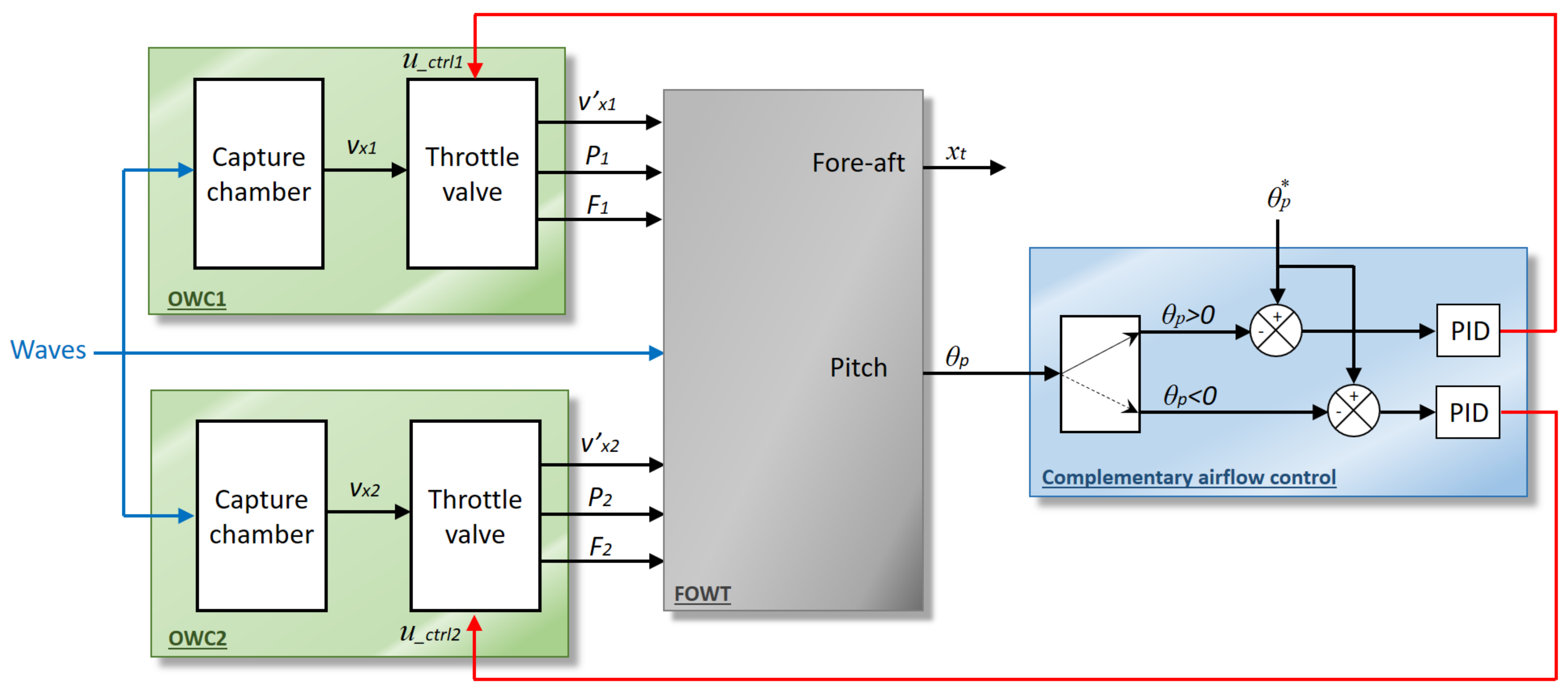
3. Proposed Complementary Airflow Control

To help stabilize the FOWT system, two OWCs have been integrated into the structure of the ITI Energy barge platform. Both OWCs are identical and have been placed on both sides of the tower (front and back) at an equal distance to maintain symmetry. By controlling the air valves of every OWC using an airflow control strategy to adjust the airflow and pressure inside the capture chambers, the OWC can help oppose some of the hydrodynamic forces.
When the platform is tilted forward, the force induced from the pressure within the capture chamber of OWC1 should be greater than that of the capture chamber of OWC2, but when the platform is tilted backward, the force induced from the pressure within the capture chamber of OWC1 should be less than that of capture chamber of OWC2. Therefore, the control for the valve in OWC1 should be activated when the pitch is positive to partially or completely close the valve plate and trap the air, which increases the pressure, whereas the control for the valve in OWC2 should open the valve to release some air and relieve the pressure. Inversely, when the pitch is negative, the control for the valve in OWC1 should open the valve plate, and the control for the valve in OWC2 should close the valve plate.
Because the OWCs are integrated into the ITI Energy barge and will have opposing moments on it, the proposed airflow control strategy relies on the platform pitch as explained in Figure 3. In practice, the input to the FOWT system is the wave elevation Z ( t ) , which can be measured by a wave height recorder installed in the central moon pool of the platform or by an acoustic Doppler current profiler (ADCP) mounted at the bottom of the barge. As for the FOWT DOFs, both the platform pitch θ p and tower top fore-aft displacement x t may be measured by two accelerometers placed at the base and top of the tower, respectively [15].
The proposed control strategy uses two PID controllers to open and close the air valves according to the platform pitch as shown in Figure 3. The input of the PID controllers is the platform pitch error and the output is the control signal of the air valves. When the valves trap or release the air in the chambers, they increase or decrease the pressure and consequently the forces acting on the barge of the FOWT system.

4. Results and Discussions

In this section, two comparative studies have been performed to show the stabilizing effect brought to the FOWT system using OWCs. The first study compares the free decay response of the FOWT with a standard ITI Energy barge to a FOWT with an OWC-based barge. The second study compares the simulation of the standard uncontrolled FOWT to the proposed OWC-based FOWT using wave input with different wave periods. In this research work, since the focus is on the platform pitch and tower top fore-aft displacement, only heading waves are considered in the simulation.

4.1. Free Decay Response

In this study, both structures are compared to understand their response and how the perturbations are damped out without any excitations. In this sense, there should not be any aerodynamic loading on the rotor from winds and no wave loading on the support structure from waves and, hence, both the hub height wind speed V w i n d ( t ) and the wave elevation Z ( t ) should be omitted. Next, an initial perturbation is provided to the system in the form of an initial platform pitch angle of 5 degrees. The obtained results are shown in Figure 4 and Figure 5.
Figure 4 shows the free decay response of the platform pitch for both structures, and it can be seen that both initially start from 5 degrees, which is the initial perturbation introduced to both systems. It can be seen that during the simulation with time, the platform pitch is damped out, but with the proposed OWC-based FOWT the platform pitch is reduced compared to the standard FOWT.
In Figure 5, the top tower fore-aft displacement is illustrated for both structures and the same can be deduced; the oscillations of the fore-aft displacement are reduced in the OWC-based FOWT compared to the standard FOWT.
Using the exponential decay method, the damping ratios for the platform pitch is of 1.84% in the case of the OWC-based FOWT structure whereas it is of 1.66% in the case of the standard FOWT structure. On the other hand, the damping ratio for the tower fore-aft is of 1.27% in the case of the OWC-based FOWT structure, whereas it is of 0.86% in the case of the standard FOWT structure. Finally, the obtained time contribution of the airflow control with respect to the settling time of the platform pitch is 45.07 s.

4.2. Simulation Results with Different Waves

To test the efficiency of the proposed OWC-based structural control, a study case considering regular waves with two different wave periods has been performed. In this simulation study, the first wave input Z ( t ) considered from 0 to 1000 s has a wave amplitude of 1 m and a wave period of 30 s, but the second wave input from 1000 to 2000 s has a wave amplitude of 1 m and a wave period of 20 s as shown in Figure 6.
When simulating the OWC-based FOWT model, the airflow speed in both OWCs is shown in Figure 7. The effect of using the proposed airflow control can be seen in both airflows of OWC1 and OWC2 in the red curves, which have been compared to the airflow of the uncontrolled system, where the valves are always open in the blue curves. It can be seen that when the control is activated the valve plates reduce the airflow speed.
The resulting pressure from the obtained airflow speed of Figure 7 are presented in Figure 8 for both OWC1 and OWC2 without and with controlled valves.
The effects of controlling the valves can be seen in the pressure of the controlled valves in the red curves. In fact, thanks to the closing of the valves, the pressure was maintained at a higher value compared to the uncontrolled pressure, in the blue curves, where it goes down to the atmospheric pressure value.
The obtained platform pitch of the OWC-based FOWT has been compared to the one of a standard barge-based FOWT which are both presented in Figure 9.
From these curves, it is clear that the PID controller manages to control the valves in accordance with the platform pitch and has successfully reduced the platform pitch for both wave periods. In fact, by zooming in the curves it is noted, in Figure 9b, that the pitch has decreased from 3.812° in a standard barge to 2.756° in an OWC-based barge with the first wave of the 30 s wave period. Moreover, with the second wave of the 20 s wave period the pitch has decreased from 3.104° in a standard barge to 1.933° in an OWC-based barge.
The obtained tower top fore-aft displacement of the OWC-based FOWT has been compared to the one of a standard barge-based FOWT and are both illustrated in Figure 10.
Similar to the platform pitch, the proposed structural control manages to reduce the tower top fore-aft displacement for both wave periods. In fact, by zooming in the curves it is noted, in Figure 10b, that the fore-aft displacement has decreased from 32.37 cm in a standard barge to 22.95 cm in an OWC-based barge with the first wave of the 30 s wave period. Moreover, with the second wave of the 20 s wave period, the fore-aft displacement has decreased from 30.663 cm in a standard barge to 19.66 cm in an OWC-based barge.

5. Conclusions

In this paper, a novel active structural control has been proposed by integrating oscillating water columns into the ITI Energy barge platform of a floating offshore wind turbine along with a complementary airflow control for the OWCs in order to help stabilize the platform by relying on the counterforces induced by the built-up pressure within the OWC air chambers to reduce the undesired platform pitch motion and the tower top fore-aft displacement mode.
A dynamic simplified linear model of the floating offshore wind turbine has been adopted in this work, emphasizing the platform pitch and the tower top fore-aft displacement DOFs. Based on this model, the pressures and forces of the OWCs have been added to be able to study the effect of using the OWCs to oppose some of the hydrodynamic forces imposed on the ITI Energy barge platform. The control is achieved by measuring the platform pitch angle that is fed to the PID controllers. The PID controllers’ outputs control the opening of the valves at the OWCs chambers, which will regulate the pressures within each air chamber accordingly.
The obtained results showed that when compared to the standard barge-based FOWT platform, the free decay response of the proposed OWC-based FOWT was further damped out. In addition, using the exponential decay method, the damping ratios for the platform pitch and tower top displacement were better in the case of the proposed OWC-based FOWT. Moreover, the comparison of both platforms with different wave periods showed that the proposed platform successfully reduces the oscillations of the platform pitch angle and tower top fore-aft displacement by an average of 32%.

Author Contributions

Conceptualization, F.M., P.A., I.G., A.J.G. and M.D.L.S.; Formal analysis, F.M., P.A., I.G., A.J.G. and M.D.L.S.; Investigation, F.M., P.A., I.G., A.J.G. and M.D.L.S.; Methodology, F.M., P.A., I.G., A.J.G. and M.D.L.S.; Supervision, I.G., A.J.G. and M.D.L.S.; Validation, F.M., P.A., I.G., A.J.G. and M.D.L.S.; Visualization, F.M., P.A., I.G., A.J.G. and M.D.L.S.; Writing—original draft, F.M., P.A., I.G., A.J.G. and M.D.L.S.; Writing—review and editing, F.M., P.A., I.G., A.J.G. and M.D.L.S. All authors have read and agreed to the published version of the manuscript.

Funding

This work was supported in part by the Basque Government, through project IT1207-19 and by the MCIU/MINECO through the projects RTI2018-094902-B-C21 and RTI2018-094902-B-C22 (MCIU/AEI/FEDER, UE).

Institutional Review Board Statement

Not applicable.

Informed Consent Statement

Not applicable.

Data Availability Statement

Not applicable.

Conflicts of Interest

The authors declare no conflict of interest.

References

  1. Snyder, B.; Kaiser, M.J. Ecological and economic cost-benefit analysis of offshore wind energy. Renew. Energy 2009, 34, 1567–1578. [Google Scholar] [CrossRef]
  2. Kaldellis, J.K.; Kapsali, M. Shifting towards offshore wind energy-recent activity and future development. Energy Policy 2013, 53, 136–148. [Google Scholar] [CrossRef]
  3. Perez-Collazo, C.; Greaves, D.; Iglesias, G. A review of combined wave and offshore wind energy. Renew. Sustain. Energy Rev. 2015, 42, 141–153. [Google Scholar] [CrossRef] [Green Version]
  4. Jonkman, J.M. Dynamics Modeling and Loads Analysis of an Offshore Floating Wind Turbine; (No. NREL/TP-500-41958); National Renewable Energy Lab. (NREL): Golden, CO, USA, 2007.
  5. Jonkman, J.M.; Matha, D. A Quantitative Comparison of the Responses of Three Floating Platform Concepts; (No. NREL/CP-500e46726); National Renewable Energy Lab. (NREL): Golden, CO, USA, 2010.
  6. Lackner, M.A. Controlling platform motions and reducing blade loads for floating wind turbines. Wind Eng. 2009, 33, 541–553. [Google Scholar] [CrossRef]
  7. Staino, A.; Basu, B. Emerging trends in vibration control of wind turbines: A focus on a dual control strategy. Philos. Trans. R. Soc. A Math. Phys. Eng. Sci. 2015, 373, 20140069. [Google Scholar] [CrossRef] [PubMed]
  8. Dinh, V.N.; Basu, B.; Nagarajaiah, S. Semi-active control of vibrations of spar type floating offshore wind turbines. Smart Struct. Syst. 2016, 18, 683–705. [Google Scholar]
  9. Lackner, M.A.; Rotea, M.A. Passive structural control of offshore wind turbines. Wind Energy 2011, 14, 373–388. [Google Scholar] [CrossRef]
  10. Si, Y.; Karimi, H.R.; Gao, H. Modeling and parameter analysis of the OC3-Hywind floating wind turbine with a tuned mass damper in nacelle. J. Appl. Math. 2013, 2013, 679071. [Google Scholar] [CrossRef] [Green Version]
  11. Luo, N.; Pacheco, L.; Vidal Seguí, Y.; Li, H. Smart structural control strategies for offshore wind power generation with floating wind turbines. Renew. Energ. Power Qual. J. (RE&PQJ) 2012, 10, 1200–1205. [Google Scholar]
  12. Stewart, G.M.; Lackner, M.A. Offshore wind turbine load reduction employing optimal passive tuned mass damping systems. IEEE Trans. Control Syst. Technol. 2013, 21, 1090–1104. [Google Scholar] [CrossRef]
  13. He, E.M.; Hu, Y.Q.; Zhang, Y. Optimization design of tuned mass damper for vibration suppression of a barge-type offshore floating wind turbine. Proc. Inst. Mech. Eng. Part M J. Eng. Marit. Environ. 2017, 231, 302–315. [Google Scholar] [CrossRef]
  14. Hu, Y.; Wang, J.; Chen, M.Z.; Li, Z.; Sun, Y. Load mitigation for a barge-type floating offshore wind turbine via inerter-based passive structural control. Eng. Struct. 2018, 177, 198–209. [Google Scholar] [CrossRef]
  15. Lackner, M.A.; Rotea, M.A. Structural control of floating wind turbines. Mechatronics 2011, 21, 704–719. [Google Scholar] [CrossRef]
  16. Si, Y.; Karimi, H.R. Gain scheduling H2/H∞ structural control of a floating wind turbine. IFAC Proc. Vol. 2014, 47, 6788–6793. [Google Scholar] [CrossRef]
  17. Hu, Y.; He, E. Active structural control of a floating wind turbine with a stroke-limited hybrid mass damper. J. Sound Vib. 2017, 410, 447–472. [Google Scholar] [CrossRef]
  18. Zhang, Y.; Zhao, X.; Wei, X. Robust structural control of an underactuated floating wind turbine. Wind Energy 2020, 23, 2166–2185. [Google Scholar] [CrossRef]
  19. Hu, J.; Zhou, B.; Vogel, C.; Liu, P.; Willden, R.; Sun, K.; Zang, J.; Geng, J.; Jin, P.; Cui, L.; et al. Optimal design and performance analysis of a hybrid system combing a floating wind platform and wave energy converters. Appl. Energy 2020, 269, 114998. [Google Scholar] [CrossRef]
  20. Sarmiento, J.; Iturrioz, A.; Ayllón, V.; Guanche, R.; Losada, I.J. Experimental modelling of a multi-use floating platform for wave and wind energy harvesting. Ocean Eng. 2019, 173, 761–773. [Google Scholar] [CrossRef]
  21. Yu, J.; Li, Z.; Yu, Y.; Hao, S.; Fu, Y.; Cui, Y.; Xu, L.; Wu, H. Design and Performance Assessment of Multi-Use Offshore Tension Leg Platform Equipped with an Embedded Wave Energy Converter System. Energies 2020, 13, 3991. [Google Scholar] [CrossRef]
  22. Kluger, J.M.; Slocum, A.H.; Sapsis, T.P. A First-Order Dynamics and Cost Comparison of Wave Energy Converters Combined with Floating Wind Turbines. In Proceedings of the 27th International Ocean and Polar Engineering Conference, San Francisco, CA, USA, 25–30 June 2017; pp. 577–585. [Google Scholar]
  23. Slocum, A.; Kluger, J.; Mannai, S. Energy Harvesting and Storage System Stabilized Offshore Wind Turbines. In Proceedings of the 2019 Offshore Energy and Storage Summit (OSES), Brest, France, 10–12 July 2019; pp. 1–6. [Google Scholar]
  24. Kamarlouei, M.; Gaspar, J.F.; Calvario, M.; Hallak, T.S.; Mendes, M.J.; Thiebaut, F.; Soares, C.G. Experimental analysis of wave energy converters concentrically attached on a floating offshore platform. Renew. Energy 2020, 152, 1171–1185. [Google Scholar] [CrossRef] [Green Version]
  25. Vijfhuizen, W.J.M.J. Design of a Wind and Wave Power Barge. Master’s Dissertation, Department of Naval Architecture and Mechanical Engineering, Universities of Glasgow and Strathclyde, Glasgow, Scotland, September 2006. [Google Scholar]
  26. M’zoughi, F.; Garrido, I.; Bouallègue, S.; Ayadi, M.; Garrido, A.J. Intelligent Airflow Controls for a Stalling-Free Operation of an Oscillating Water Column-Based Wave Power Generation Plant. Electronics 2019, 8, 70. [Google Scholar] [CrossRef] [Green Version]
  27. M’zoughi, F.; Garrido, I.; Garrido, A.J.; De La Sen, M. ANN-Based Airflow Control for an Oscillating Water Column Using Surface Elevation Measurements. Sensors 2020, 20, 1352. [Google Scholar] [CrossRef] [PubMed] [Green Version]
  28. M’zoughi, F.; Garrido, I.; Garrido, A.J.; De La Sen, M. Self-Adaptive Global-Best Harmony Search Algorithm-Based Airflow Control of a Wells-Turbine-Based Oscillating-Water Column. Appl. Sci. 2020, 10, 4628. [Google Scholar] [CrossRef]
  29. Jonkman, J. Influence of control on the pitch damping of a floating wind turbine. In Proceedings of the 46th IEEE Aerospace Science Meeting Exhibit, Reno, NV, USA, 7–10 January 2008; pp. 1–15. [Google Scholar]
  30. Aboutalebi, P.; M’zoughi, F.; Garrido, I.; Garrido, A.J. Performance Analysis on the Use of Oscillating Water Column in Barge-Based Floating Offshore Wind Turbines. Mathematics 2021, 9, 475. [Google Scholar] [CrossRef]
  31. Aubault, A.; Alves, M.; Sarmento, A.N.; Roddier, D.; Peiffer, A. Modeling of an oscillating water column on the floating foundation WindFloat. In Proceedings of the International Conference on Offshore Mechanics and Arctic Engineering, Rotterdam, The Netherlands, 19–24 June 2011; pp. 235–246. [Google Scholar]
  32. Henriques, J.C.C.; Sheng, W.; Falcão, A.; Gato, L.M.C. A comparison of biradial and wells air turbines on the Mutriku breakwater OWC wave power plant. In Proceedings of the ASME 2017 36th International Conference on Ocean, Offshore and Arctic Engineering, Trondheim, Norway, 25–30 June 2017; pp. 1–12. [Google Scholar]
  33. M’zoughi, F.; Bouallegue, S.; Garrido, A.J.; Garrido, I.; Ayadi, M. Fuzzy gain scheduled PI-based airflow control of an oscillating water column in wave power generation plants. IEEE J. Ocean. Eng. 2018, 44, 1058–1076. [Google Scholar] [CrossRef]
  34. Torresi, M.; Camporeale, S.M.; Strippoli, P.D.; Pascazio, G. Accurate numerical simulation of a high solidity Wells turbine. Renew. Energy 2008, 33, 735–747. [Google Scholar] [CrossRef]
Figure 1. Schematic of a floating offshore wind turbine on an ITI Energy barge platform.
Mathematics 09 01364 g001
Figure 2. Simplified model of floating offshore wind turbine.
Mathematics 09 01364 g002
Figure 3. Proposed complementary airflow control for FOWT stabilization.
Mathematics 09 01364 g003
Figure 4. Free decay response for the platform pitch in the standard FOWT and OWC-based FOWT.
Mathematics 09 01364 g004
Figure 5. Free decay response for the tower top fore-aft displacement in the standard FOWT and OWC-based FOWT.
Mathematics 09 01364 g005
Figure 6. Considered wave input with two different wave periods.
Mathematics 09 01364 g006
Figure 7. Obtained aiflow in the OWCs without and with airflow control. (a) Airflow in OWC1. (b) Airflow in OWC2.
Mathematics 09 01364 g007
Figure 8. Obtained pressure in the OWCs without and with airflow control. (a) Airflow in OWC1. (b) Airflow in OWC2.
Mathematics 09 01364 g008
Figure 9. Obtained platform pitch in both structures. (a) Platform pitches. (b) Zoom-in of the platform pitches.
Mathematics 09 01364 g009
Figure 10. Obtained tower fore-aft displacement in both structures. (a) Tower fore-aft displacements. (b) Zoom-in of the tower fore-aft displacements.
Mathematics 09 01364 g010
Table 1. Parameters of the NREL 5 MW wind turbine and the ITI barge platform.
Wind TurbineITI Energy Barge
FeatureValueFeatureValue
Rating power5 MWPlatform size40 m × 40 m × 10 m
Baseline controlVariable speed, collective pitchPlatform mass including Ballast5,452,000 kg
Cut-in, rated, cut-out wind speed3 m/s, 11.4 m/s, 25 m/sAnchor depth150 m
Cut-in, rated rotor speed6.9 rpm, 12.1 rpmNumber of mooring lines8
Tower mass347, 460 kgLine diameter0.0809 m
Rotor diameter126 mLine mass density130.4 kg/m
Hub height90 m
Table 2. Structural parameters of the FOWT model.
TowerBarge Platform
ParameterValueParameterValue
Stiffness k t = 9.7990 10 9 (N m rad 1 )Stiffness k p = 1.4171 10 9 (N m rad 1 )
Damping coefficient d t = 2.1032 10 7 (N m s rad 1 )Damping coefficient d p = 3.6374 10 7 (N m s rad 1 )
Inertia I t = 1.8217 10 9 (kg m 2 )Inertia I p = 1.6945 10 9 (kg m 2 )
Table 3. Parameters of the integrated oscillating water columns.
Capture ChamberWells Turbine
FeatureValueFeatureValue
Chamber’s inner width w c = 10 mBlade numbern = 5
Chamber’s inner length l c = 10 mBlade spanb = 0.21 m
Chamber’s inner height h c = 10 mBlade chord lengthl = 0.165 m
Water density ρ w = 1029 kg/m 3 Turbine mean radiusr = 0.375 m
Atmospheric density ρ a = 1.19 kg/m 3 Cross-sectional areaa = 0.4417 m 2
Atmospheric pressure p a = 101.325 kPa
Publisher’s Note: MDPI stays neutral with regard to jurisdictional claims in published maps and institutional affiliations.

