Abstract
The Poisson surface reconstruction algorithm has become a very popular tool of reconstruction from point clouds. If we reconstruct each region separately in the process of multi-reconstruction, then the reconstructed objects may overlap with each other. In order to reconstruct multicomponent surfaces without self-intersections, we propose an efficient multi-reconstruction algorithm based on a modified vector-valued Allen–Cahn equation. The proposed algorithm produces smooth surfaces and closely preserves the original data without self-intersect. Based on operator splitting techniques, the numerical scheme is divided into one linear equation and two nonlinear equations. The linear equation is discretized using an implicit method, and the resulting discrete system of equation is solved by a fast Fourier transform. The two nonlinear equations are solved analytically due to the availability of a closed-form solution. The numerical scheme has merit in that it can be straightforwardly applied to a graphics processing unit, allowing for accelerated implementation that performs much faster than central processing unit alternatives. Various experimental, numerical results demonstrate the effectiveness and robustness of the proposed method.
1. Introduction
Multimaterial reconstruction from multi-labeled point clouds is of significant importance in many disciplines, such as mechanical engineering [1,2]. Such point clouds are sampled by a multi-camera vision system and provide the local connectivity of objects. For instance, in the reversed engineering problem, multicomponent surfaces/volumes of the object should be reconstructed without self-intersections so that a multimaterial 3D printer can process these models. The challenges in multi-reconstruction mainly lie in the following two aspects: how to handle the contacting regions and how to maintain the original topology. Up until now, many reconstruction methods have been developed to address modeling from point clouds. In addition, modeling multi-labeled domains have been extensively studied in reconstructing surfaces or volumes from sets of planar cross-sections. The authors proposed a phase field framework for 3D surface reconstruction from parallel slices based on the modified Cahn–Hilliard equation [3,4,5]. All of the above-mentioned reconstruction methods can process one region or separated regions but cannot process contacting regions. If we reconstruct surfaces from each single-labeled point, the resulted objects may overlap with each other (see Figure 1). Here, the surface/volumes-overlapping problem refers to the phenomenon that the volume voxel is defined for more than one value for the label. Hence, we need to develop an efficient algorithm to reconstruct multicomponent surfaces from point clouds without overlapping regions.
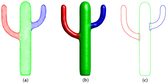
Figure 1.
(a) The point cloud. (b) The surfaces that are obtained by signal Poisson surface reconstruction [6]. (c) The result in the cross-view of (b).
In this paper, we propose an efficient multi-reconstruction method from point clouds. The proposed method is based on the Allen–Cahn (AC) equation [7], which has the motion of the mean curvature flow [8,9,10,11]. Under the mean curvature flow, the reconstructed surface is smooth. The Allen–Cahn equation has been applied to a wide range of problems such as crystal growth [12,13,14], image analysis [15,16,17,18], triply-periodic minimal surface [19,20], and volume reconstruction [21,22,23], and topology optimization [24]. In this paper, we use the Allen–Cahn equation in different contexts and applications. To our best knowledge, the presented approach is the first algorithm using the modified vector-valued Allen–Cahn equation for multi-reconstruction from point clouds. Our method can guarantee the production of well-reconstructed multicomponent surfaces without self-intersections. Our main contributions in this paper are as follows:
- The first algorithm using a modified vector-valued Allen–Cahn equation for multi-reconstruction from point clouds, which can reconstruct multicomponent surfaces without self-intersections;
- Based on operator splitting techniques, the proposed numerical scheme is simple to implement;
- The algorithm can be straightforwardly applied to a graphics processing unit (GPU), allowing for accelerated implementation that performs many times faster than other central processing units (CPU).
The remainder of the paper is organized as follows. Section 2 briefly reviews some related works. In Section 3, we introduce the preliminary. In Section 4, the governing equations for the multi-reconstruction from a point cloud are presented. Section 5 presents the operator splitting scheme, and Section 6 states the numerical results of several computational examples. Conclusions are drawn in Section 7.
2. Related Work
2.1. Implicit Surface Reconstruction
Implicit methods usually deal with data imperfections [25,26]. Most of the implicit implemented function are based on the signed distance function, radial basis functions, piecewise polynomial functions, or indicator functions. Hoppe et al. [27] defined the signed distance field by using the tangent plane projection. In [28], Carry et al. employed the polyharmonic radial basis function to reconstruct the manifold surfaces. This technique is well-suited to deal with non-uniformly sampled point clouds. However, it fails to reconstruct a proper surface from the point clouds with noises. Ohtake et al. [29] used the piecewise quadratic function and partition-of-unity weights to capture the local surface shape. This approach has the benefit of sharp feature reconstruction. Manson et al. [30] presented a streaming method for surface reconstruction from large point sets by using the wavelets method. The Poisson method [6] is a popular implicit method because of its resilience to data noises. However, it tends to smooth geometric details. To overcome this defect, Kazhdan and Hoppe [31] extended the Poisson method by explicitly incorporating the points as interpolation constraints by formulating a screened Poisson surface reconstruction method. Bretin et al. proposed a variational approach for the reconstruction of a volume from slices by using a minimizer of a geometric regularity criterion, Willmore energy, with inclusion–exclusion constraints associated with the cross-sections. In [32], the authors considered the problem of 3D shape reconstruction from multimodal data, given uncertain calibration parameters. To analytically and compactly represent the object, they exploited a parametric level set method, which utilized ellipsoidal radial basis functions. Kim and Lee proposed a modified Cahn–Hilliard equation for three-dimensional volume reconstruction from 2D slices [4]. In order to accurately satisfy the constraints while obtaining a smooth result, they applied a presmoothing procedure based on anisotropic diffusion to the slices.
2.2. Multi-Reconstruction
Volume fractions and implicit functions are typical approaches for defining the multi-labeled domains. Hirt and Nichols [33] developed an efficient interface reconstruction method by treating complicated free boundary configurations as the material interfaces. To obtain the finer interface details, the authors utilized information about the position of the material centroid for the interface reconstruction [34,35,36]. Lemoine et al. [37] proposed a fast analytic reconstruction formula replacing the original minimization stage in the framework of the moment-of-fluid method. This algorithm can provide accurate results with a lower computational cost. Kikinzon et al. [38] extended the moment-of-fluid method to simultaneously establish the geometry and topology. Since the modified moment-of-fluid method does not require data from its neighbors, the modified moment-of-fluid method is well suitable for massively parallel computing. Yuan et al. [39] introduced a class of object-space multiphase implicit functions that are capable of accurately modeling objects with multiple internal regions. Zhang and Qian [40] resolved the topology ambiguity method by analyzing a hybrid Octree method with both cubic and tetrahedral leaf cells. This method can apply to both homogeneous and multimaterial domains. Da et al. [41] presented the first non-manifold triangle mesh tracking method to simultaneously maintain intersection-free meshes. Their methods support multimaterial remeshing and topological operations. In the context of multi-reconstruction from cross-sections, Liu et al. [42] proposed an extension of the projection-based approach that can deal with curve networks of arbitrary topology on cross-section planes with arbitrary orientations. Bermano et al. [43] used multiple implicit functions to extract multi-labeled material interfaces from sampled planar cross-sections of arbitrary orientation. Huang et al. [44] developed the first reconstruction algorithm for multi-labeled material interfaces that allows for explicit topology control. Li et al. [45] constructed 3D models of multi-labeled objects from sets of cross-sections by employing a multicomponent Cahn–Hilliard system. This algorithm is simple to implement and produces smooth surfaces. However, all the mentioned multi-labeled material reconstruction methods can not directly reconstruct surfaces from multi-labeled point clouds. To our best knowledge, the presented approach is the first algorithm using the modified vector-valued Allen–Cahn equation for multi-reconstruction from point clouds. Our method can guarantee the production of well-reconstructed multicomponent surfaces without self-intersections.
3. Preliminary: Poisson Surface Reconstruction
The Poisson reconstruction method creates smooth surfaces [6] by using an indicator (defined as 1 at the voxel inside the solid M and 0 at the voxel outside the solid M). Given the vector field defined by the data samples S, the goal of the Poisson reconstruction method is to find the scalar function by minimizing
Here, and . ∇ is the gradient operator and is the inner product. By applying the divergence operator to form the Poisson equation, the governing equation can be obtained by
where and are the Laplacian and divergence operators, respectively. The vector field is defined by convolving the normal field with a Dirac delta function:
where is the inward surface normal at , is the Dirac delta function, and is the boundary of the solid M. After solving Equation (2), we can obtain the solution , which is also called the indicator function [46,47,48,49,50]. Then, we define the reconstructed surface S as the half isosurface of the scalar function .
4. Methodology
Using the Poisson surface reconstruction [6], the indicator function of material can be determined by a discrete function in the domain . Here, if the voxel is determined as a volume voxel, otherwise . As mentioned in the above section, contains lots of good voxels and few self-intersection regions. We want to obtain a new smooth discrete function , which approaches the given without self-intersections. To realize this goal, we propose the following total free energy
Here, the double-well potential function can enforce to be approximately 0 or 1. is the positive constant and relates to the phase transition width. is the positive constant. Minimizing the first two terms of the functional is equivalent to finding the steady-state solution of the gradient flow equation:
Here, t is the time variable. Equation (5) is the well-known Allen–Cahn equation [7], which has the motion of mean curvature [8]. This ensures that the obtained surface is smooth. Minimizing the third term of the functional enforces that the new smooth discrete function is almost the same as those in the originally known volume .
The sum of the different material components should be equal to 1, i.e., , which implies that any voxel is defined as one label (See Figure 2). Therefore, if we minimize the functional and keep , the obtained surface will be similar to and will be smooth without self-intersections. To minimize the proposed functional , we consider the gradient descent method in the space:
where
This Lagrangian multiplier guarantees that the constraint is satisfied:

Figure 2.
Reconstructed surface in the cut view. The red and blue regions represent the different materials. The yellow region represents the overlapping region.
The total energy can be decreased over time as follows:
Here, we have used the periodic boundary conditions for . It should be noted that the solution of Equations (6)–(8), which are derived from a constrained gradient flow of the free energy functional, is unique.
5. Numerical Method
We utilize an efficient operator splitting scheme for Equation (6) on the discrete domain . Let be the uniform grid size. Let , , , , , and . Let and be approximations of , where is the time step. We split the original problem (6) into a sequence of simpler problems as
and
Here, , , and denote the solutions of the subproblem (11)–(13), respectively. For a fixed , we can see that Equation (11) is a separable ordinary differential equation, i.e., . We can obtain the following solution:
Next, we employ an implicit method to Equation (12):
This discrete scheme can be solved by a fast Fourier transform as follows. The discrete Fourier transform for , , and is defined as
where , , and , respectively. The inverse discrete Fourier transform is
We apply the Fourier transform to both sides of Equation (15):
Then, we can get
For a fixed , Equation (13) is also a separable ordinary differential equation, i.e., With the initial condition , we can obtain the following solution after :
Then, we set and complete the one time step processing. Finally, the proposed scheme can be written as follows:
Therefore, the numerical scheme (Equations (21)–(23)) is simple to implement because Equation (6) is divided into one linear equation and two nonlinear equations. The linear equation is discretized using an implicit method, and the resulting discrete system of equations is solved by a fast Fourier transform. The two nonlinear equations are solved analytically due to the availability of a closed-form solution. Our method is fast since the computational complexities of two nonlinear equations are and the computational complexity of the linear equation is . Therefore, our method is simple and fast. Our method also has merit in that it can be straightforwardly applied to GPU-accelerated implementation by using the MATLAB Parallel Computing Toolbox.
The operator splitting-based hybrid numerical scheme (Equations (21)–(23)) has a good numerical stability. For Equation (21), we get , because and . Since Equation (22) is a heat-type equation, its implicit numerical scheme can allow the use of a large time step. For Equation (23), we get
Thus, if , then . Therefore, the numerical solution is bounded, which implies that our proposed scheme allows using a larger time step. The hybrid numerical scheme (Equations (21)–(23)) has first-order accuracy in time and second-order accuracy in space because Equation (22) is employed by using an implicit method and Equations (21) and (23) are two ordinary equations. It should be noted that in the analysis, we can not prove the unconditional stability of our method. On the other hand, for the computational simulation, the results with a large time step are generally less accurate than those obtained by using a small time step, because using a larger time step would cause a large error of the numerical solutions. Therefore, a small time step will be used for highly accurate numerical solutions. Therefore, to maintain the numerical accuracy and reduce computational costs, we propose to use in this paper.
6. Experimental Results
In this section, various numerical results will be performed to demonstrate the accuracy and efficiency of our algorithm. We consider the numerical result as a steady-state solution if the relative error for every component is less than a tolerance , i.e., for . Unless otherwise specified, we use the following parameters: , , , , and . The reconstructed surface S is defined as the half isosurface of the phase field . Note that the original input points cloud is taken from [51].
6.1. Basic Mechanism of the Algorithm
We start with an example that illustrates the basic mechanism of our algorithm. As is shown in Figure 3a, let us consider two-labeled oriented point samples of two intersecting spheres. The radii of the red sphere and blue sphere are 100 and 75, respectively. Figure 3b,c shows the reconstructed surface obtained by the Poisson reconstruction and our method, respectively. The overlapping region exists in the result of Poisson reconstruction, as shown in the left figure of Figure 4. On the other hand, our proposed method can overcome this difficulty, as shown in the right figure of Figure 4. Figure 4 illustrates the evolution of our modified multicomponent AC equation in the cross-view. From left to right, the illustration represents , 1, and , respectively. It is obvious that our method can reconstruct multicomponent surfaces without overlapping regions.

Figure 3.
(a) The point cloud that is downsampled for display. (b,c) The surfaces that are obtained by Poisson surface reconstruction and our method, respectively.

Figure 4.
The evolution of our method in the cut view. (a–c) The contours from t = 0, 1, 5.5 in the cross-view, respectively.
6.2. Performance on the Complex Reconstruction
We use the proposed method to reconstruct the surface from the complex multi-labeled point clouds. We compared our results with the results attained by Poisson surface reconstruction in Figure 5a,c, respectively. The overlapping regions are obvious. On the other hand, our method can avoid self-intersections and provide a high-quality repairing result, as shown in Figure 5b,d. The mesh grid size is . The computation of our method takes about s to perform on the GPU.
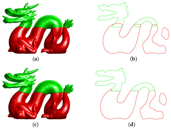
Figure 5.
(a,c) The results of Poisson reconstruction and our proposed method in the whole view, respectively. (b,d) The results in the cross-view of (a,c), respectively.
6.3. Multicomponent Surface Reconstruction
Our method can process the multicomponent surface reconstruction from the multi-labeled point clouds. Figure 6a–c shows the results with two-component, three-component, and four-component reconstructions, respectively. Here, a mesh grid is used. Our proposed method achieves fast convergence with few iterations. These simulations demonstrate that our proposed method can perform well for multicomponent surface reconstruction.
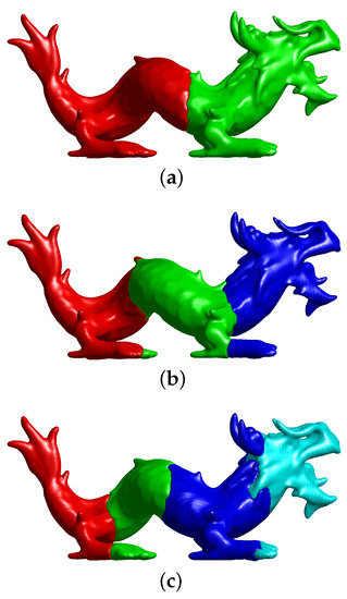
Figure 6.
Multicomponent reconstruction of our proposed method. (a) Two-component reconstruction. (b) Three-component reconstruction. (c) Four-component reconstruction.
Figure 7 shows the four-component surface reconstruction of the tablet. From left to right, these are the input real point clouds and final reconstructions with different views. As can be observed, our proposed method can handle the complex morphology, and the reconstructed surface is smooth.
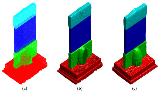
Figure 7.
Four-component surface reconstruction of real point clouds. (a) Input data set. (b,c) Final reconstructions with different views.
6.4. Multi-Reconstruction with Different Density of Point Data
Figure 8 shows our multi-reconstruction results for the happy buddha surface with different densities of input point data. Figure 8a is the initial input data. Note that for the purposes of better visualization, we displayed the points more sparsely than the original density. Observing these results in Figure 8, we can see that with a low density of input point data, our proposed method can still reconstruct the surface with finer details and features. The agreement between the results obtained by different sampling densities suggests that our method can successfully reconstruct the surface with the low sampling density.
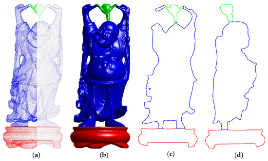
Figure 8.
Multi-reconstruction with different densities of point data. (a) Initial input data. (b) Reconstructed surfaces. (c,d) The results in the different cross-view of (b).
6.5. Parameter Sensitivity Analysis
In this section, we will analyze the parameter sensitivity of our proposed algorithm. The fidelity term in Equation (6) keeps the solution close to the original result of the Poisson reconstruction. balances the motion by the mean curvature flow and the fitting term. If , (6) becomes the classical Allen–Cahn equation. Consequently, the interface of phase field will shrink with time. That is, if is too small, the detailed information of the original object will be lost, as shown in Figure 9a. On the other hand, if is too large, the fidelity term is dominant so that for any time. Thus, the reconstructed surfaces will overlap with each other, as shown in Figure 9c. Therefore, we should choose an appropriate . In this paper, we propose to use . The role of is related to the material transition width. We take the same initial condition except for different values of . Observing the results of Figure 10, we can observe that if is small, the surface of objects is sharp and the volumes have many holes. If is too large, the surface becomes over-smooth and the volumes overlap with each other. In this paper, we propose using .
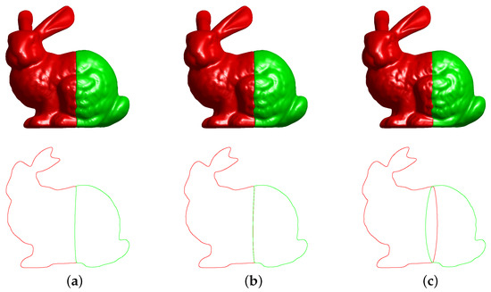
Figure 9.
Illustration for the parameter sensitivity analysis. (a) . (b) . (c) .
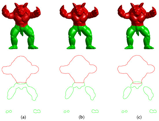
Figure 10.
Illustration for the parameter sensitivity analysis. (a) . (b) . (c) .
6.6. Performance of Our Method
Table 1 presents the information on the grid size, iteration numbers, CPU and GPU times. CPU(pro) and GPU(pro) are the times taken to process the multi-reconstruction by using the computer’s central processing unit and graphics processing unit, respectively. The CPU and GPU times in seconds of our calculations, which are performed in MATLAB, are measured on a desktop with an NVIDIA GeForce GTX 1050Ti and a quad-core Intel Core i5. We can observe that our proposed method obtains fast convergence after a few iterations because the computational complexities of the two nonlinear equations are and the computational complexity of the linear equation is . Furthermore, we can employ a GPU-accelerated method that performs many times faster than CPU-only alternatives. It should be noted that the gain is related to the speed of the computation and our method may perform well in a high-performance computing cluster system.

Table 1.
List of grid size, iterations, CPU times (second), GPU times (second), and errors. CPU(pro) and GPU(pro) are the times taken to process the multi-reconstruction by using the computer’s central processing unit and graphics processing unit, respectively.
6.7. Comparisons with Related Works and Accuracy Test
To evaluate the accuracy of our proposed method, we compare our results with the exact solution. Here, the error for every component is defined as , where is the result of Poisson reconstruction from the all of the point clouds. We can see that the reconstructed surfaces are close to the exact solution, as shown in Table 2.

Table 2.
Accurate evaluation of our method.
Based on the Cahn–Hilliard system [18,52,53], Li et al. proposed an efficient and robust algorithm to reconstruct the volumes of multi-labeled objects from sets of cross-sections without overlapping regions, artificial gaps, or mismatched interfaces [45]. Our algorithm can also handle cross-sections wherein different regions have different labels. Firstly, we obtain the point clouds from the given set of slice data by using the MATLAB contour file (See Figure 11a,b). Then, we perform our method to reconstruct the surface, as shown in Figure 11b–d. Figure 11e–h are the two-dimensional results at the slice data , and 110, respectively. Here, a mesh grid is used. A similar test has been performed in [45]. Observing these numerical results, we can see that our proposed method is qualitatively in good agreement with the results in [45]. Our method is simpler and easy to perform compared to Li et al.’s method because their method is a fourth-order nonlinear partial differential equation and is hard to solve in an explicit manner. On the other hand, our method is a second-order partial differential equation and is easy to solve in the splitting manner. Note that this comparison is unfair because Li et al.’s method [45] can directly reconstruct the volumes of multi-labeled objects from sets of cross-sections. However, our approach should firstly translate the slice data into the point clouds and then perform the method to reconstruct surfaces, which may lead to missing data during data transforming. To our best knowledge, the presented approach is the first algorithm using the modified vector-valued Allen–Cahn equation for multi-reconstruction from point clouds.
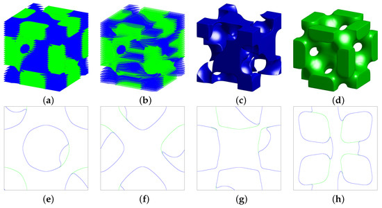
Figure 11.
Comparisons with the related work [45]. (a) Given set of slice data. (b) Transformed point clouds. (c) Reconstructed Schwarz diamond minimal surface. (d) Reconstructed Schoen’s F-RD minimal surface. (e–h) Two-dimensional results at the slice data , and 110, respectively.
7. Conclusions and Future Work
We have shown that surface reconstruction can be expressed as a modified vector-valued Allen–Cahn equation, which obtains a smooth surface due to the motion of the mean curvature flow, and we have demonstrated that this approach can robustly reconstruct multicomponent surfaces without self-intersections. Based on operator splitting techniques, our numerical scheme is simple to implement and achieves fast convergence, which can be regarded as an advantage for real-time application. The relative computational cost is also presented. Our algorithm can also handle cross-sections wherein different regions have different labels. Compared to Li et al.’s method [45], our method is simpler and easier to perform. This comparison is considered unfair because Li et al.’s method [45] reconstructs the multi-labeled volumes from sets of cross-sections, and our method is a multi-reconstruction from point clouds. One limitation of our proposed method is that it suffers from high memory usage. As an example, Figure 7 shows the reconstruction of a stele, constructing the voxel grid at a resolution of . The reconstruction was computed with GB of RAM. Trying to compute an equivalent reconstruction with methods, such as the Octree-based approach, would require constructing at a depth of nine and may require an excess of GB of memory. In future work, we will present a parallel Octree-based mesh refinement solver for the current algorithm.
Author Contributions
J.W. and Z.S. contributed equally to this work. Methodology, J.W. and Z.S.; software, Z.S.; validation, J.W.; formal analysis, J.W.; data curation, J.W.; writing—original draft preparation, J.W. and Z.S.; writing—review and editing, J.W. and Z.S.; All authors have read and agreed to the published version of the manuscript.
Funding
Funds for the Central Universities (No. XTR042019005).
Institutional Review Board Statement
Not applicable.
Informed Consent Statement
Informed consent was obtained from all subjects involved in the study.
Data Availability Statement
See the Institutional Review Board Statement.
Acknowledgments
The authors are grateful to Y. Li and reviewers, whose valuable suggestions significantly improved the quality of this paper.
Conflicts of Interest
The authors declare no conflict of interest.
References
- Shammaa, M.H.; Ohtake, Y.; Suzuki, H. Segmentation of multi-material ct data of mechanical parts for extracting boundary surfaces. Comput. Aided Des. 2010, 42, 118–128. [Google Scholar] [CrossRef]
- Zhang, Y.; Hughes, T.J.; Bajaj, C.L. An automatic 3d mesh generation method for domains with multiple materials. Comput. Methods Appl. Mech. Eng. 2010, 199, 405–415. [Google Scholar] [CrossRef]
- Li, Y.; Shin, J.; Choi, Y.; Kim, J. Three-dimensional volume reconstruction from slice data using phase-field models. Comput. Vis. Image Underst. 2015, 137, 115–124. [Google Scholar] [CrossRef]
- Kim, J.; Lee, C.O. Three-dimensional volume reconstruction using two-dimensional parallel slices. SIAM J. Imaging Sci. 2019, 12, 1–27. [Google Scholar] [CrossRef]
- Zou, Q. A PDE model for smooth surface reconstruction from 2d parallel slices. IEEE Signal Process. Lett. 2020, 27, 1015–1019. [Google Scholar] [CrossRef]
- Kazhdan, M.; Bolitho, M.; Hoppe, H. Poisson surface reconstruction. In Proceedings of the Fourth Eurographics Symposium on Geometry, Cagliari, Sardinia, 26–28 June 2006; Volume 7, pp. 61–70. [Google Scholar]
- Allen, S.M.; Cahn, J.W. A microscopic theory for antiphase boundary motion and its application to antiphase domain coarsening. Acta Metall. 1979, 27, 1085–1095. [Google Scholar] [CrossRef]
- Ilmanen, T. Convergence of the Allen-Cahn equation to brakke’s motion by mean curvature. J. Differ. Geom. 1993, 38, 417–461. [Google Scholar] [CrossRef]
- Li, Y.; Jeong, D.; Kim, H.; Kim, J. Comparison study on the different dynamics between the Allen–Cahn and the Cahn–Hilliard equations. Comput. Math. Appl. 2019, 77, 311–322. [Google Scholar] [CrossRef]
- Long, J.; Luo, C.; Yu, Q.; Li, Y. An unconditional stable compact fourth-order finite difference scheme for three dimensional Allen-Cahn equation. Comput. Math. Appl. 2019, 77, 1042–1054. [Google Scholar] [CrossRef]
- Li, Y.; Kim, J. An unconditionally stable hybrid numerical method for solving the Allen-Cahn equation. Comput. Math. Appl. 2010, 60, 1591–1606. [Google Scholar] [CrossRef]
- Karma, A.; Rappel, W.J. Quantitative phase-field modeling of dendritic growth in two and three dimensions. Phys. Rev. E 1998, 57, 4323. [Google Scholar] [CrossRef]
- Li, Y.; Lee, H.; Kim, J. A fast, robust, and accurate operator splitting method for phase-field simulations of crystal growth. J. Cryst. Growth 2011, 321, 176–182. [Google Scholar] [CrossRef]
- Li, Y.; Lee, H.; Kim, J. Phase-field simulations of crystal growth with adaptive mesh refinement. Int. J. Heat Mass Transf. 2012, 55, 7926–7932. [Google Scholar] [CrossRef]
- Beneš, M.; Chalupeckỳ, V.; Mikula, K. Geometrical image segmentation by the Allen–Cahn equation. Appl. Numer. Math. 2004, 51, 187–205. [Google Scholar] [CrossRef]
- Esedog, S.; Tsai, Y.H.R. Threshold dynamics for the piecewise constant Mumford—Shah functional. J. Comput. Phys. 2006, 211, 367–384. [Google Scholar] [CrossRef]
- Kay, D.A.; Tomasi, A. Color image segmentation by the vector-valued Allen–Cahn phase-field model: A multigrid solution. IEEE Trans. Image Process. 2009, 18, 2330–2339. [Google Scholar] [CrossRef] [PubMed]
- Li, Y.; Kim, J. Multiphase image segmentation using a phase-field model. Comput. Math. Appl. 2011, 62, 737–745. [Google Scholar] [CrossRef]
- Li, Y.; Guo, S. Triply periodic minimal surface using a modified Allen—Cahn equation. Appl. Math. Comput. 2017, 295, 84–94. [Google Scholar] [CrossRef]
- Li, Y.; Xia, Q.; Yoon, S.; Lee, C.; Lu, B.; Kim, J. A simple and efficient volume merging method for triply periodic minimal structure. Comput. Phys. Commun. 2021, 264, 107956. [Google Scholar] [CrossRef]
- Li, Y.; Lee, D.; Lee, C.; Lee, J.; Lee, S.; Kim, J.; Ahn, S.; Kim, J. Surface embedding narrow volume reconstruction from unorganized points. Comput. Vis. Image Underst. 2014, 121, 100–107. [Google Scholar] [CrossRef]
- Li, Y.; Kim, J. Fast and efficient narrow volume reconstruction from scattered data. Pattern Recognit. 2015, 48, 4057–4069. [Google Scholar] [CrossRef]
- Li, Y.; Lan, S.; Liu, X.; Lu, B.; Wang, L. An efficient volume repairing method by using a modified Allen-Cahn equation. Pattern Recognit. 2020, 107, 107478. [Google Scholar] [CrossRef]
- Yu, Q.; Wang, K.; Xia, B.; Li, Y. First and second order unconditionally energy stable schemes for topology optimization based on phase field method. Appl. Math. Comput. 2021, 405, 126267. [Google Scholar]
- Tang, Y.; Feng, J. Multi-scale surface reconstruction based on a curvature-adaptive signed distance field. Comput. Graph. 2018, 70, 28–38. [Google Scholar] [CrossRef]
- Morel, J.; Bac, A.; Véga, C. Surface reconstruction of incomplete datasets: A novel poisson surface approach based on csrbf. Comput. Graph. 2018, 74, 44–55. [Google Scholar] [CrossRef]
- Hoppe, H.; DeRose, T.; Duchamp, T.; McDonald, J.; Stuetzle, W. Surface reconstruction from unorganized points. In Proceedings of the 19th Annual Conference on Computer Graphics and Interactive Techniques, New York, NY, USA, 1 July 1992; pp. 71–78. [Google Scholar]
- Carr, J.C.; Beatson, R.K.; Cherrie, J.B.; Mitchell, T.J.; Fright, W.R.; McCallum, B.C. Reconstruction and representation of 3d objects with radial basis functions. In Proceedings of the 28th Annual Conference on Computer Graphics and Interactive Techniques, Los Angeles, CA, USA, 12–17 August 2001; pp. 67–76. [Google Scholar]
- Ohtake, Y.; Belyaev, A.; Alexa, M.; Turk, G.; Seidel, H.P. Multi-level partition of unity implicits. In Proceedings of the ACM SIGGRAPH 2003 Papers, Los Angeles, CA, USA, 1 July 2003; p. 173-es. [Google Scholar]
- Manson, J.; Petrova, G.; Schaefer, S. Streaming surface reconstruction using wavelets. In Computer Graphics Forum; Blackwell Publishing Ltd.: Oxford, UK, 2008; Volume 27, pp. 1411–1420. [Google Scholar]
- Kazhdan, M.; Hoppe, H. Screened poisson surface reconstruction. ACM Trans. Graph. 2013, 32, 1–13. [Google Scholar] [CrossRef]
- Eliasof, M.; Sharf, A.; Treister, E. Multimodal 3D shape reconstruction under calibration uncertainty using parametric level set methods. SIAM J. Imaging Sci. 2020, 13, 265–290. [Google Scholar] [CrossRef]
- Hirt, C.W.; Nichols, B.D. Volume of fluid (vof) method for the dynamics of free boundaries. J. Comput. Phys. 1981, 39, 201–225. [Google Scholar] [CrossRef]
- Dyadechko, V.; Shashkov, M. Moment-of-Fluid Interface Reconstruction. Technical Report; Los Alamos National Laboratory (LA-UR-05-7571). 2005. Available online: https://citeseerx.ist.psu.edu/viewdoc/download?doi=10.1.1.77.7998&rep=rep1&type=pdf (accessed on 29 April 2021).
- Dyadechko, V.; Shashkov, M. Reconstruction of multi-material interfaces from moment data. J. Comput. Phys. 2008, 227, 5361–5384. [Google Scholar] [CrossRef]
- Ahn, H.T.; Shashkov, M. Multi-material interface reconstruction on generalized polyhedral meshes. J. Comput. Phys. 2007, 226, 2096–2132. [Google Scholar] [CrossRef]
- Lemoine, A.; Glockner, S.; Breil, J. Moment-of-fluid analytic reconstruction on 2D cartesian grids. J. Comput. Phys. 2017, 328, 131–139. [Google Scholar] [CrossRef]
- Kikinzon, E.; Shashkov, M.; Garimella, R. Establishing mesh topology in multi-material cells: Enabling technology for robust and accurate multi-material simulations. Comput. Fluids 2018, 172, 251–263. [Google Scholar] [CrossRef]
- Yuan, Z.; Yu, Y.; Wang, W. Object-space multiphase implicit functions. ACM Trans. Graph. 2012, 31, 1–10. [Google Scholar] [CrossRef]
- Zhang, Y.; Qian, J. Resolving topology ambiguity for multiple-material domains. Comput. Methods Appl. Mech. Eng. 2012, 247, 166–178. [Google Scholar] [CrossRef]
- Da, F.; Batty, C.; Grinspun, E. Multimaterial mesh-based surface tracking. ACM Trans. Graph. 2014, 33, 112-1–112-11. [Google Scholar] [CrossRef]
- Liu, L.; Bajaj, C.; Deasy, J.O.; Low, D.A.; Ju, T. Surface reconstruction from non-parallel curve networks. In Computer Graphics Forum; Blackwell Publishing Ltd.: Oxford, UK, 2008; Volume 27, pp. 155–163. [Google Scholar]
- Bermano, A.; Vaxman, A.; Gotsman, C. Online reconstruction of 3d objects from arbitrary cross-sections. ACM Trans. Graph. 2011, 30, 1–11. [Google Scholar] [CrossRef]
- Huang, Z.; Zou, M.; Carr, N.; Ju, T. Topology-controlled reconstruction of multi-labelled domains from cross-sections. ACM Trans. Graph. 2017, 36, 1–12. [Google Scholar] [CrossRef]
- Li, Y.; Wang, J.; Lu, B.; Jeong, D.; Kim, J. Multicomponent volume reconstruction from slice data using a modified multicomponent Cahn–Hilliard system. Pattern Recognit. 2019, 93, 124–133. [Google Scholar] [CrossRef]
- Li, Y.; Jung, E.; Lee, W.; Lee, H.-G.; Kim, J. Volume preserving immersed boundary methods for two-phase fluid flows. Int. J. Numer. Methods Fluids 2012, 69, 842–858. [Google Scholar] [CrossRef]
- Li, Y.; Yun, A.; Lee, D.; Shin, J.; Jeong, D.; Kim, J. Three-dimensional volume-conserving immersed boundary model for two-phase fluid flows. Comput. Methods Appl. Mech. Eng. 2013, 257, 36–46. [Google Scholar] [CrossRef]
- Olshanskii, M.; Xu, X.; Yushutin, V. A finite element method for Allen–Cahn equation on deforming surface. Comput. Math. Appl. 2021, 90, 148–158. [Google Scholar] [CrossRef]
- Marseglia, G.; Medaglia, C.M.; Ortega, F.A.; Mesa, J.A. Optimal alignments for designing urban transport systems: Application to Seville. Sustainability 2019, 11, 5058. [Google Scholar] [CrossRef]
- Carrese, S.; Cuneo, V.; Nigro, M.; Pizzuti, R.; Ardito, C.F.; Marseglia, G. Optimization of downstream fuel logistics based on road infrastructure conditions and exposure to accident events. Transp. Policy 2019. [Google Scholar] [CrossRef]
- The Stanford Volume Data Archive, Copyright©2000 MarcLevoy. 2001. Available online: http://graphics.stanford.edu/data/3Dscanrep (accessed on 29 April 2021).
- Cahn, J.W.; Hilliard, J.E. Free energy of a nonuniform system I. Interfacial free energy. J. Chem. Phys. 2004, 28, 258–267. [Google Scholar] [CrossRef]
- Li, Y.; Choi, J.I.; Kim, J. Multi-component Cahn–Hilliard system with different boundary conditions in complex domains. J. Comput. Phys. 2016, 323, 1–16. [Google Scholar] [CrossRef]
Publisher’s Note: MDPI stays neutral with regard to jurisdictional claims in published maps and institutional affiliations. |
© 2021 by the authors. Licensee MDPI, Basel, Switzerland. This article is an open access article distributed under the terms and conditions of the Creative Commons Attribution (CC BY) license (https://creativecommons.org/licenses/by/4.0/).