Abstract
In boilers with biomass fuel, a significant problem is caused due to the slag layer formed from the unburned particles during combustion. In the paper, a tube cleaning method from slag is proposed. The method is based on the impact effect of the end of the tube with the aim to produce vibration for slag elimination. The tube is modeled as a clamped-free nonlinear oscillatory system. The initial impact of the tube causes vibrations. The mathematical model of the system is a nonlinear partial differential equation with zero initial deflection. To obtain the ordinary differential equations, the Galerkin method is applied. By discretizing the equation into a finite degree of freedom system, using the undamped linear mode shapes of the straight beam as basic functions, the reduced order model, consisting of ordinary differential equations in time, is obtained. The ordinary time equations are analytically solved by adopting the Krylov–Bogoliubov procedure. Special cases of nonlinear differential equations are investigated. In the paper, the influence of the nonlinear parameters and initial conditions on the vibration properties of the tube is obtained. We use the procedure developed in the paper and the analytical results for computation of the impact parameters of the cleaning device.
1. Introduction
Nowadays, there is a tendency to increase the application of biomass fuels for heating and electricity production. Usually, this fuel is a mixture of a conventional one (for example, coal) and of alternative ones such as herbaceous materials (straw [1], corn, cereal, grass [2], agricultural and crop residues [3], wooden biomass [4], etc.). Biomass fuel is utilized as a cheaper alternative in comparison to conventional fuels, but it seems to cause some troubles in heat boiler operation. Namely, during the combustion, the high content of mineral constituents in fuel create serious deposition problems on tubes and surfaces, including fouling, slagging, and corrosion [5]. Agricultural residues are often ash-rich and commonly contaminated with impurities, which cause increased ash deposition [6,7]. Namely, the unburned materials, transported in the fuel gas, form deposit layers on heat transfer surfaces in biomass boilers [8]. Fractions of material with high adhesion energy settle on surfaces, accumulate under specific conditions, and produce a thick layer that reduces heat transfer between the fuel gas and the water of steam in the tubes and decreases the efficiency of the boiler [9,10]. Depending on the boiler where the biomass fuel is utilized, the problem of slagging, fouling, and corrosion is different [11]. Fouling in boilers not only decreases the plant efficiency by clogging but can lead to over-pressure in the boiler, and the fouling can lead to boiler damage by the abrasion and erosion of boiler tubes and high-temperature corrosion [12]. To improve the efficiency of the biomass heat boiler, the aforementioned different technical obstacles, produced by slagging and fouling, need to be eliminated.
Nowadays, various mitigation strategies are developed to overcome the problem with slagging and deposits [13]. The most often applied methods for the elimination of deposited materials is by the continuous preventive cleaning of boiler heating surfaces and also pipelines, bins, heat exchangers, ventilation systems, etc. [14]. Conventional cleaning techniques employ the effects of direct fluid impact and local washing away of deposits [15,16]. These are achieved with steam soot blowers, air soot blowers, steam lancing, or water jet washing. The technique is not complex, but it depends on some uncertain slagging conditions. In addition, steam and air jets form unwanted effects: erosion as a consequence of the abrasive action of hard ash components swept away by the jets, reduction of the furnace exit gas temperature, and a negative effect on the boiler operating parameters. Energy and fluid consumption as well as substantial installation costs also count as shortcomings. Another cleaning method is with the pneumoimpulsive technique, which is based on the shock-wave impact on slag deposits. A pneumoimpulsive generator produces an air jet, which within a few fractions of a second exhausts and produces a powerful impact that treats the boiler heating surfaces [17]. Unfortunately, the method has similar shortcomings to the aforementioned methods. To remove the deposited material, a device with pressure waves [18,19,20,21] generated by detonation is also applied. The deposit removal mechanism is based on the mechanical shock, which affects the breakup of the material deposited on tube packages and other boiler interior surfaces. Despite the simplicity of this cleaning method, it is rarely applied because the detonation is not controlled and often causes damages to tubes and the system as a whole. To overcome this lack, we suggest the mechanism of tube cleaning based on the mechanical impact on the solid, which excites vibration. The vibration of tubes and boiler walls would loosen the deposited material. The aim of this paper is to develop the computation procedure for obtaining the necessary impact parameters as functions of vibration properties of tubes.
In the literature, the influence of the impact excitation on the beam is investigated experimentally [22] and analytically [23]. The beam is excited with the shock force modeled as a half-sine shock function. The effect of the shock force, which acts in time on the vibration property of the beam, is calculated. In our investigation, we modify the model. The effect of the impact force, as the initial condition for the motion of the tube, is considered. Using the Euler–Bernoulli theory, the mathematical model of the tube with slag is given as a nonlinear partial differential equation. The Galerkin method is applied for transformation of the equation into ordinary differential equations. By discretizing the equation into a finite degree of freedom system, using the undamped linear mode shapes of the straight beam as basic functions, the reduced order model, consisting of ordinary differential equations in time, is obtained. In the paper, the Krylov–Bogoliubov method is adopted for solving the nonlinear equations. According to the principle of linear momentum and of angular momentum, the initial impact conditions are formulated. Solving the vibration equation for certain initial conditions, the relation between impact parameters and vibration properties of the tube are obtained. The vibration properties of the tube depend on the tube dimension and wall configuration, the amount and features of the deposited material, and the frequency and amplitude of the excited vibrations, which are all analyzed. The procedure suggested in the paper is numerically tested and suggested for application in the tube cleaning device.
The paper is divided into five sections. After the Introduction, in the Section 2, the physical and mathematical model of the real heating tube system is given. The tubes are assumed to be clamped-free beams, which have bending vibration. Due to the boundary conditions, the frequencies of vibration are given. The influence of the impact initial conditions on the vibration properties of the tube is considered. Using the basic impact laws, the initial conditions for the tube are introduced. An analytical solution of the nonlinear partial differential equation with zero deflection initial conditions is developed. Some special cases of nonlinearity and the first mode of vibration are investigated. In Section 3, the procedure for determination of the parameters of the impact device for tube cleaning is introduced. Based on the analytic results obtained in the previous section, the prediction of vibration due to various values of impact force for systems with certain geometric and physic properties of tubes is discussed. Analytically obtained results are compared with experimental ones in Section 4. The paper ends with the Conclusion.
2. Mathematical Model and Approximate Solving Method
The basic element of the biomass boiler is the tube, which is modeled as a clamped-free system (Figure 1). The upper end of the tube is fixed, while the lower end is free to move in the horizontal direction due to the action of a horizontal impact. The tube is assumed to have the rigidity EI, length l, and unit mass ρA. Due to slagging on the inner tube surface, a nonlinear force acts, which is of a polynomial-type deflection function. Namely, the force is the product of the α-th order of deflection of the tube (α is an integer or non-integer) and of the coefficient kα, which depends on the physical property of the fouling.
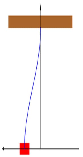
Figure 1.
Clamped-free beam.
Using the Euler–Bernoulli beam theory, the differential equation for bending vibration is obtained
where y = y(x,t) is the displacement function, x is the independent length coordinate, and t is time. The boundary conditions for the clamped-free beam in Figure 1 are as follows: the displacement and the inclination of the clamped end are zero, while the inclination angle and the transversal force of the free end are zero.
It is worth mentioning that the coefficient kα in Equation (1) is small in comparison to the other coefficients and the partial differential equation is with small nonlinearity. Equation (1) with boundary conditions (2) does not have an exact analytic solution. In this paper, the approximate procedure for solving (1) is introduced.
2.1. Approximate Solving Procedure
Let us assume that the weak nonlinear Equation (1) is the perturbed version of the linear differential equation ()
According to this assumption, it is supposed that the solution of (1) has to be the perturbed version of the solution of the linear function (3). Using the Galerkin procedure, the solution is assumed as the inner product of the space function X(x) dependent on x and time function which depends only on t, i.e.,
The perturbed version of solution (4), which corresponds to Equation (1), is
where X(x) is the space function, which corresponds to the linear modes of (3), and T(t) is the unknown perturbed time function. Substituting the assumed solution (5) into (3) and (2), the linear modes are
where i = 1, 2, 3, …, is an unknown constant, and is the solution of the frequency equation
Solving (7), we obtain
Substituting (5) into (1), multiplying with the expression of the linear modes (6) and integrating along the length l of the beam, we have
The mode shapes satisfy the orthogonality condition
where is a constant dependent on and is the undamped natural frequency for the i-th mode given by
Integrating (10) with orthogonality condition (9), a nonlinear second-order ordinary differential equation follows
In this paper, the Krylov–Bogolubov method [24] is adopted for solving the weak nonlinear differential equation (12). Assuming that (12) is the perturbed version of the linear differential equation , it is supposed that the solution of (12) has to be the perturbed version of the solution of the linear equation
where B and θ are arbitrary constants. Based on (13), the solution of the perturbed Equation (12) is assumed as
where B(t), , and are time dependent. Comparing the time derivative of (14)1 with (14)2, the constraint follows
where and . Substituting the first derivative of (14)2 and the relation (14) into (12), it yields
Equations (15) and (16) are two first-order differential equations, which correspond to (12). Rewriting (15) and (16), we obtain
To solve Equation (17) is not an easy task. It is at this point that the averaging of Equation (17) over the period of the function ψ is introduced. It yields
Integrating (18), it is
where
B and are constants.
After substituting (19) into (14), the general form of the approximate solution of (12) is obtained
where and are constants (i = 1, 2, …) and is the frequency of vibration, which depends on the natural frequency and initial amplitude
Let us rewrite the solution (21) into
where constants and satisfy the relations
Substituting (6) and (23) into (5), assuming that Di = 1 and after some modification, the solution of (1) and its first time derivative are
Constants and have to satisfy two sets of initial conditions: initial displacement y (0,t) and velocity distribution along the tube ()x,0.
2.2. Influence of Initial Conditions on the Tube Vibration
One of the most important problems is how to obtain the initial conditions for beam vibration. Vibration of the tube is caused by an impact at the free end. Let us assume a tube with the concentrated mass m =ρAl and moment of inertia JC = (ml2/3) for the mass center C settled in the middle of the length of the tube. Due to the action of the pulse force , it is supposed that the position of the tube does not change, but there is a sudden jump in the angular velocity and velocity of the mass center in the y direction. If the velocity of the tube before impact is zero, due to the principles of linear and angular momentums, the velocity of mass center and angular velocity after impact satisfy the relations
where is the unknown impact reaction. Using the velocity–angular velocity relation , the angular velocity after impact is obtained
The angular velocity of the tube after impact depends on the impact force and the physical (ρ) and geometric (A, l) properties of the tube. However, the most important influence on the angular velocity gives the impact force.
The impact force depends on the acting mass M, its acceleration a0, and impulse duration time τ
It is obvious that the impulse force directly depends on the acting mass and its acceleration. Substituting (29) into (28), we have
Based on the previous consideration, the initial conditions are as follows
Introducing (30) into (25), we obtain that Then, the relations (25) and (26) simplify into
where
Using (30)2 and (32), it is
Multiplying (33) with a periodical function and after integration over the length of the beam l, we obtain
where . In the relation (34), the influence of the parameters of slag are not explicitly evident. For the certain excitation parameter and vibration mode, the amplitude and frequency product are constant. In Figure 2, the amplitude–frequency diagram for various values of the initial excitation parameter for the first mode of vibration is plotted. It is obvious that the amplitude of vibration is decreasing with the increase of the frequency of vibration.
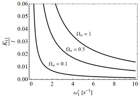
Figure 2.
Amplitude–frequency diagram for various values of Ωa.
Substituting (33) into (34), it is
The expression (35) is a strong nonlinear algebraic equation where the values of have to be calculated. Substituting the obtained values of into (31), the approximate solution of (1) would follow.
2.3. Special Cases
Let us analyze the vibration of the tube initially excited with the impact force. The amplitude and frequency of vibration are investigated.
- (a)
- For that case, when the slag–tube system is modeled as a linear system and α = 1, the amplitude relation (35) simplifies into , where the amplitude of vibration of the clean tube (without slag) iswhere is the coefficient of elasticity of the slag, the natural frequency of the clear tube, and
Analyzing relation (36), it is obvious that the amplitude of vibration of the tube without slag differs for the modes but depends on the impact force and the geometric properties of the tube. In Figure 3, the amplitude–excitation diagrams (36) for various modes i are plotted. It is seen that the relation is linear.
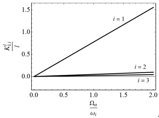
Figure 3.
diagram for various modes.
The increase of amplitude with frequency is significantly faster for lower modes than for higher modes of vibration. Based on this analysis, it is concluded that for practical engineering consideration, the modes higher than the first can be omitted, and the approximate deflection function is
- (b)
- For the tube with slag and a quadratic nonlinear property, the amplitude–frequency relation (35) iswhere , , is the natural frequency (11), and is the amplitude of vibration of the clean tube (36). Using the relation (38), the influence of the coefficient k2 on the level of the amplitude of vibration —i.e., diagrams for various order of modes (i = 1, 2, 3)—are plotted (see Figure 4.). The diagrams show the dependence of the amplitude of vibration on the coefficient of nonlinearity for the case when the excitation is constant.
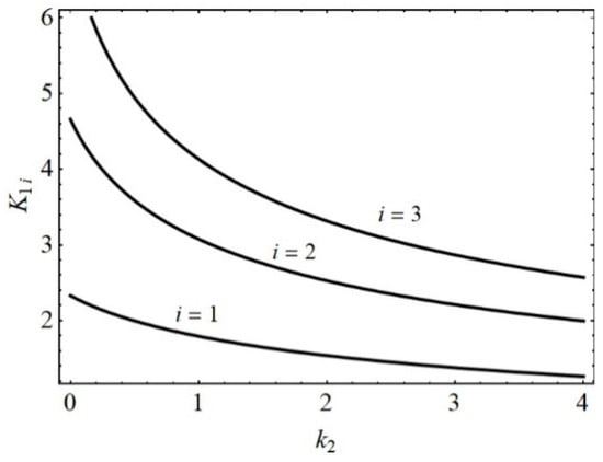 Figure 4. diagrams for various modes.
It is concluded that the amplitude of vibration decreases with increase of the coefficient k2. The amplitude decrease is faster for lower modes of vibration than for higher ones. If the coefficient k2 is extremely high, for all modes of vibration, the amplitude tends to zero.
- (c)
- Based on (33), the frequency of vibration of the tube with square nonlinearity is , i.e.,
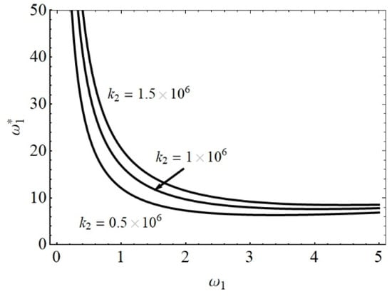
Figure 5.
diagram for various values of k2.
From the diagrams in Figure 5, it is obvious that the nonlinearity k2 has a significant influence on the frequency of vibration for the tubes with small natural frequency. For the tube with certain natural frequency, the frequency of vibration is higher if the parameter of the nonlinearity k2 is bigger. The influence of the parameter k2 variation on the frequency of vibration is small for the tubes with high natural frequency. Namely, the frequency of vibration tends to the value of the natural one.
3. Procedure for Calculation of Parameters of the Tube Cleaning Impact Device
In this section, a procedure for determination of the parameters of the device for the elimination of slag from the inner side of the tube is developed. The cleaning is realized by the action of an impact force on the free end of the tube, which causes vibration. Based on the vibration properties for the clean tube and their comparison with those for the tube with slag, parameters of the cleaning impact device are calculated. The procedure is as follows:
- Let us assume the boundary value for the tube material which satisfies the relation i.e., where is the known strength of the tube material and is the security number for impact.
- For the tube with known geometric properties and moment of inertia using the relation , the maximal moment Mmax is calculated. Thus, for the tube with dimensions ϕD/d and physical property , the value of is obtained.
- According to (31), the time variation of the bending moment along the tube isAnalyzing the first term of the series expansion in (40) and comparing with (37), it is obtained that the relation between the moment and deflection distribution isThe appropriate relation between the maximal deflection ymax and the maximal moment Mmax follows as
- In the previous section, maximal deflection for the first mode of vibration for the clean tube is calculated. Equating Expression (42) for ymax with the deflection , we obtainwhere the first natural frequency of the clear tube is according to (11)
- Using relations (42), (43), and the value of the natural frequency (44), the limit value for the excitation frequency depending on the geometric and physical properties of the tube are obtained
- Introducing the formula , the limit value of the impact force is due to (29)For realization of the maximal impact, the mass M with acceleration a0 and duration has to act, i.e.,
- It is suggested to calculate the time interval for impact action equating it with the period of tube vibration. Thus, according to (37), the time interval between two maximal amplitudes is
- Substituting (48) into (38), the approximate value of the impact force is
The impact force (49) has to act in the time interval (48).
After acting of the impulse force, it is necessary to prove that the cleaning of the tube is over. It is recommended to measure the frequency and deflection of the tube. The cleaning of the tube is finished if the frequency of vibration is ω and the deflection of the free end of the tube is .
4. Numerical Example
Let us consider the vertical panel, which contains tubes made of steel with Young’s modulus of elasticity E = 2.1 × 10¹¹ N/m2 and density ρ = 7.8 × 10³ kg/m3. For σ = 5.7 × 10⁸ N/m2 and a security coefficient of ξ = 2.5, the relations (47)–(49) for maximal impact, time, and impact force are as follows.
For tubes with length l = 6 m and cross-section dimensions , the numerical values of maximal impact, time, and impact force for tube cleaning are calculated and presented in Table 1. Thus, according to the values in the Table 1, for the panel with 38 tubes with dimensions , the maximal impact force has to be smaller than 395.70 N; i.e., the product of the impact mass and its velocity is 64.746 kgm/s.

Table 1.
, , and for various dimensions of tubes.
The number of impacts depends on the quantity of slag on the tube, and it has to be determined experimentally. If the frequencies of vibration of the tube reach the values of the frequencies (11) of the tube (given in Table 2), it can be concluded that the tube is clean.
Table 2.
List of frequencies.
Thus, for the tube , the first three eigenfrequencies are .
The calculated values are compared with those obtained experimentally [25]. For the tube with dimensions , the first three measured frequencies are 6.6 s−1, 35.5 s−1, and 84.2 s−1. Comparing these values with the analytically obtained ones, it is concluded that they are in good agreement.
5. Conclusions
In this paper, a method for the evacuation of solid particles from the biomass boiler tube using the vibration, caused by an impact at the end of the tube, is developed. The impact properties and the transversal vibration of the tube, which is modeled as a clamped–free beam, are considered. During the cleaning of the tube, the free vibration, initially excited with an impact, is analyzed. The model of the tube is nonlinear due to the slag on the tube surface. The bending vibration of the tube is a partial nonlinear differential equation with zero initial deflection and an initial velocity that depends on the impact parameters. To solve the equation, an approximate analytical procedure is developed. Special cases of nonlinearity are considered. The following were found:
- If the tube is clean, the amplitude of vibration is the linear function of the excitation frequency. The increase of the amplitude with the increase of the excitation frequency is the most significant for the first vibration mode. For the second and higher modes, the effect of excitation frequency on the amplitude increase is negligible.
- The amplitude of vibration of the tube with slag depends on the tube rigidity. If the rigidity is higher, the amplitude of vibration is smaller. Thus, the amplitude of vibration decreases with the increase of the rigidity of the tube.
- Comparing the frequency properties of the tube with slag with the frequency of the clean tube, it is obvious that increasing the rigidity of the tube also increases the frequency of vibration. If the rigidity of the tube due to slag is higher, the frequency of vibration of the tube is higher than the frequency of the clean tube.
- The impulse parameters of the device that are necessary for cleaning the tube with slag depend on the dimensions of the tube, its rigidity, and its nonlinear properties. For the cleaning of tubes with the same rigidity, the impact force for cleaning has to be higher for the tubes with bigger cross-sections, and the time interval for the action of the cleaning device has to be shorter.
- The impact of the device has to be repeated until the frequency of vibration of the tube does not reach the value of the frequency of the clean tube.
Finally, it is concluded that the problem of slag and fouling elimination or reduction can be obtained by increasing the vibration frequency of the tube and by shortening the time intervals for application of the impact technique with adequate vibration intensities reduction. So, the serious deposit agglomeration is prevented, and cleaning of the tube is obtained.
Author Contributions
Conceptualization, D.C.; methodology, L.C.; validation, M.Z. and I.B.; formal analysis, N.H.; investigation, L.C.; resources, D.C.; writing—original draft preparation, L.C.; visualization, M.Z. and I.B.; supervision, N.H. All authors have read and agreed to the published version of the manuscript.
Funding
This research received no external funding.
Acknowledgments
This work was supported by a grant of the Romanian Ministry of Research and Innovation, project number10PFE/16.10.2018, PERFORM-TECH-UPT—The increasing of the institutional performance of the Polytechnic University of Timișoara by strengthening the research, development and technological transfer capacity in the field of “Energy, Environment and Climate Change”, within Program 1—Development of the national system of Research and Development, Subprogram 1.2—Institutional Performance—Institutional Development Projects—Excellence Funding Projects in RDI, PNCDI III”.
Conflicts of Interest
The authors declare no conflict of interest.
References
- Xu, X.G.; Li, S.Q.; Li, G.D.; Yao, Q. Effect of co-firing straw with two coals on the ash deposition behavior in a down-fired pulverized coal combustor. Energy Fuels 2010, 24, 241–249. [Google Scholar] [CrossRef]
- Szemmelveisz, K.; Szucs, I.; Palotas, A.B.; Winkler, L.; Eddings, E.G. Examination of the combustion conditions of herbaceous biomass. Fuel Process. Technol. 2009, 90, 839–847. [Google Scholar] [CrossRef]
- Wang, G.; Pinto, T.; Costa, M. Investigation on ash deposit formation during the co-firing of coal with agricultural residues in a large-scale laboratory furnace. Fuel 2014, 117, 269–277. [Google Scholar] [CrossRef]
- Stam, A.F.; Haasnoot, K.; Brem, G. Superheater fouling in a BFB boiler firing wood-based fuel blends. Fuel 2014, 135, 322–331. [Google Scholar] [CrossRef]
- Obernberger, I. Decentralized biomass combustion: State of the art and future development. Biomass Bioenergy 1998, 14, 33–56. [Google Scholar] [CrossRef]
- Li, G.; Li, S.; Xu, X.; Huang, Q.; Yao, Q. Dynamic behavior of biomass ash deposition in a 25 kW one-dimensional down-fired combuster. Energy Fuels 2014, 28, 219–227. [Google Scholar] [CrossRef]
- Orberg, H.; Jansson, S.; Kalen, G.; Thyrel, M.; Xiong, S. Combustion and slagging behavior of biomass pellets using a burner cup developed for ash-rich fuels. Energy Fuels 2014, 28, 1103–1110. [Google Scholar] [CrossRef]
- Sandberg, J.; Fdhila, R.B.; Dahlquist, E.; Avelin, A. Dynamic simulation of fouling in a circulating fluidized biomass-fired boiler. Appl. Energy 2011, 88, 1813–1824. [Google Scholar] [CrossRef]
- Llorente, M.J.F.; Garcia, J.E.C. Comparing methods for predicting the sintering of biomass ash in combustion. Fuel 2005, 84, 1893–1900. [Google Scholar] [CrossRef]
- Standstrom, K.; Mueller, C.; Hupa, M. Development of an ash particle deposition model considering build-up and removal mechanisms. Fuel Process. Technol. 2007, 88, 1053–1060. [Google Scholar] [CrossRef]
- Li, L.; Yu, C.; Huang, F.; Bai, J.; Fang, M.; Luo, Z. Study on the deposits derived form a biomass circulating fluidized bed boiler. Energy Fuels 2012, 26, 6008–6014. [Google Scholar] [CrossRef]
- Miles, T.R.; Miles, T.R., Jr.; Baxter, L.L.; Bryers, R.W.; Jenkins, B.M.; Oden, L.L. Boiler deposits from firing biomass fuels. Biomass Bioenergy 1996, 10, 125–138. [Google Scholar] [CrossRef]
- Bilirgen, H. Slagging in PC boilers and developing mitigation strategies. Fuel 2014, 115, 618–624. [Google Scholar] [CrossRef]
- Cveticanin, L.; Cveticanin, D. Cleaning methods of heat surfaces in biomass-fired boilers: A review. World J. Eng. Res. Technol. WJERT 2018, 4, 215–235. [Google Scholar]
- Romeo, L.M.; Gareta, R. Fouling control in biomass boilers. Biomass Bioenergy 2009, 33, 854–861. [Google Scholar] [CrossRef]
- Smajevic, I.; Hanjalic, K. 20 Jahre erfolgreiche Anwendung mit der Stosswellen-Reinigungstechnik in einem kohlebefeuerten Kraftwerk. Vgb Power Tech. 2004, 5, 1–9. [Google Scholar]
- Agiulin, S.G.; Nikolaev, S.F.; Zveginstev, V.I.; Yurkin, I.A.; Shabanov, I.I.; Palkin, V.F.; Sergienko, S.P.; Vlasov, S.M. Studying the effectiveness of using pneumo-impulsive technology for cleaning the platen of the PK-38 boiler at the Nazarovo district power station. Therm. Eng. 2014, 61, 658–665. [Google Scholar] [CrossRef]
- Hanjalic, K.; Smajevic, I. Detonation-wave technique for on-load deposit removal from surfaces exposed to fouling: Part I—Experimental investigation and development of the method. AsmeJ. Eng. Gas. Turbines Power 1994, 116, 223–230. [Google Scholar] [CrossRef]
- Hanjalic, K.; Smajevic, I. Detonation-wave technique for on-load deposit removal from surfaces exposed to fouling: Part II—Full-scale application. AsmeJ. Eng. Gas. Turbines Power 1994, 116, 231–240. [Google Scholar] [CrossRef]
- Hanjalic, K.; Smajevic, I. Further experience in using detonation waves for cleaning boiler heating surfaces. Int. J. Energy Res. 1993, 17, 583–595. [Google Scholar] [CrossRef]
- Smajevic, I.; Hanjalic, K. Twenty-years of experience with on-load detonation-wave deposit removal from gas-side boiler surfaces in a coal-fired power plant. In Proceedings of the 2003 International Joint Power Generation Conference Power, 16–19 June 2003, Atlanta, GA, USA.
- Davtalab, S.; Woo, K.C.; Pagwiwoko, C.P.; Lenci, S. Nonlinear vibrations of a multi-span continuous beam subject to periodic impact excitation. Meccanica 2016, 50, 1227–1237. [Google Scholar] [CrossRef]
- Younis, M.I.; Miles, R.; Jordy, D. Investigation of the response of microstructures under the combined effect of mechanical shock and electrostatic forces. J. Micromechanics Microengineering 2006, 16, 2463–2474. [Google Scholar] [CrossRef]
- Cveticanin, L. Strong Nonlinear Oscillators, 2nd ed.; Springer: Berlin, Germany, 2018. [Google Scholar]
- Khushnood, S.; Nizam, L.A. Experimental study on cross-flow induced vibrations in heat exchanger tube bundle. China Ocean. Eng. 2017, 31, 91–97. [Google Scholar] [CrossRef]
© 2020 by the authors. Licensee MDPI, Basel, Switzerland. This article is an open access article distributed under the terms and conditions of the Creative Commons Attribution (CC BY) license (http://creativecommons.org/licenses/by/4.0/).