Abstract
This paper proposes a novel photovoltaic water pumping system (PVWPS) with an improved performance and cost. This system doesn’t contain a DC-DC converter, batteries nor rare-earth motors. Removing the aforementioned components will reduce the whole cost and increase the reliability of the system. For enhancing the performance of the PVWPS, a ferrite magnet synchronous reluctance motor (FMSynRM) is employed. Besides, the motor inverter is utilized to drive the motor properly and to extract the maximum available power of the PV system. This is performed using a suggested control strategy that controls the motor inverter. Furthermore, to show the effectiveness of the proposed PVWPS, the performance of the proposed system is benchmarked with a PVWPS that is employing a pure SynRM. Moreover, the complete mathematical model of the system components and the control is reported. It is proved that the flow rate employing the proposed system is increased by about 29.5% at a low irradiation level (0.25 kW/m2) and 15% at a high irradiation level (1 kW/m2) compared to the conventional solar system using a pure synchronous reluctance motor (SynRM). An experimental laboratory test bench is built to validate the theoretical results presented in this research work. Good agreement between the theoretical and the experimental results is proved.
1. Introduction
Due to increasing CO2 and the global warming problem, as a result of using traditional energy sources, renewable energy has been receiving a great attention in the current decade. This is thanks to (1) availability in all countries (2) no CO2 emissions and hence no impact on the environment, (3) inexhaustibility and (4) less maintenance requirements [1,2,3,4,5,6]. Therefore, several countries have put a goal to electrify and use green energy in all industrial applications [7,8,9,10]. Solar is one of the most available renewable energy sources in all countries, particularly in Africa in which agriculture is a main source of employment [1,2]. Thanks to the progress in photovoltaic (PV) cells technology, their cost has decreased and their efficiency has increased gradually. This will enable more penetration of this technology in the future [2,3].
Water pumping is one of the key applications of the solar systems particularly for agriculture and irrigation purposes [3]. A typical PV water pumping system (PVWPS) contains of a solar panels, power electronic converter, motor, pump as well as batteries in some cases [7,8,9,10]. This system is characterized by a relatively high capital cost and a low overall efficiency due to the solar array. Thus, it is mandatory to optimally size the various components of the system to minimize the cost of energy production and to improve energy efficiency [10].
Through the last few years, several electric motors, converters and control schemes have been investigated to improve the performance (efficiency and flow rate) and to decrease the size and cost of the whole PVWPS [5,6,7,8,9,10,11,12,13,14,15,16,17,18,19,20,21,22,23,24,25]. For example, in [11], an induction motor is used in a photovoltaic pumping system without considering batteries. However, such system uses a DC-DC converter for increasing the generated power from the solar array, which increases the total cost and losses of the system. To further improve the performance of this system, the authors in [12,13] proposed to maximize the solar array output power using the motor inverter, i.e., removing the DC-DC converter. Besides, the authors in [14] have proposed to use sensorless control techniques to reduce the necessary sensors of the control system. To this end, this system offers numerous benefits like low cost, high reliability and less maintenance [15]. However, the rotor copper losses of induction motors account for up to 25% of the total motor losses and dominate significantly in partial loads. The rotor losses reduce the efficiency of the motor and hence the entire system [16]. Therefore, synchronous motors have received an increased interest in the solar pumping systems. Permanent magnet synchronous motors (PMSMs) are employed in the solar pumping system in [17,18,19,20,21,22]. For example, in [17], a speed sensorless PMSM-driven water pump based on inverter fed from the solar array is presented. The maximum output power of PVWPS is achieved employing only a voltage sensor together with the implemented speed sensorless control scheme. This system is efficient thanks to using only an inverter without DC-DC converter, removing motor speed and solar array currents sensors and using a permanent magnet motor. This type of motors has the advantages of high power/volume, which is required in submersible pumps, high efficiency and good power factor. Certainly, these advantages will enhance the performance of the PVWPS. Though, PMSMs use rare-earth magnets, which are characterized by the high cost, unstable market price and their manufacturing is harmful for the environment. In addition, the environmental conditions (e.g., temperature) could lead to demagnetization of the magnets. This makes the reluctance machines to be an attractive alternative for both induction and PMSMs. Switched and synchronous reluctance machines have been used in the solar pumping system in [7,8,9] and [23,24,25]. In [23], a four-phase switched reluctance motor driven by a mid-point converter in solar pumping system is presented. This system contains neither DC-DC converter nor current sensors, which makes the system more reliable, efficient and less costly. In [24,25], a solar PVWPS based on a synchronous reluctance motor is introduced. A control system is proposed for increasing the output power from the PV system and to drive the motor properly using the motor inverter. The control system can work properly for both uniform and partial shading irradiation distributions over the solar array. However, switched reluctance motors have a high vibration, which affects the lifetime of the coupling and the bearing as well as the pump. In addition, they require a complicated control to work efficiently. Synchronous reluctance motors have a low power factor which means an increased inverter rating. In addition, a proper design is mandatory to keep the torque ripple within the permissible range. Moreover, both machines have a lower power/volume, power factor and efficiency compared to permanent magnet motors.
To combine the advantages of permanent magnet and reluctance motors, this paper proposes to use a ferrite magnet synchronous reluctance motor (FMSynRM) to enhance the efficiency, cost and reliability of the solar pumping system. FMSynRMs have received a remarkable attention from the researcher in the last few years [26,27,28,29,30]. This is thanks to their advantages such as about 75% of the delivered torque results from the rotor saliency. The remaining 25% of the torque comes from the ferrite magnets [28,30]. Besides, the ferrite magnets are available in the market with lower cost than rare-earth magnets. Further, the cost of ferrite magnet ranges from 7 USD/kg to 14 USD/kg, compared to 100$/kg for neodymium magnet as reported in [31]. Moreover, they can withstand higher temperatures before the demagnetization problem occurs. The proposed system will be used in pumping water during the day for irrigation or other human requirements, and therefore neither batteries nor DC-DC converter are necessary. A proposed control strategy to increase the output power from the PV system and to drive the motor at the maximum torque per ampere is done based on the motor inverter. To the best of the author’s knowledge, this work presents a novel solar pumping system that shows an improved energy extraction and usage as well as an increased reliability and efficiency. The proposed system is not reported before through the literature.
2. Description of the Suggested PVWPS
The diagram of the suggested PVWPS is illustrated in Figure 1. Unlike the conventional PVWPS, in this system a solar array supplies the motor via a three-phase voltage source inverter. Besides, a ferrite magnet synchronous reluctance motor drives centrifugal pump. Moreover, a proposed control system (will be shown later) is implemented to increase the PV output power and also to drive the motor properly. The detailed description of the various components of the system will be shown in the next subsection.
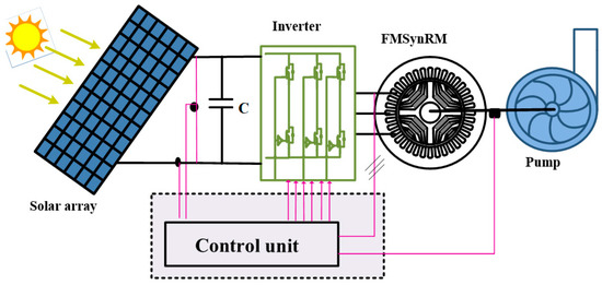
Figure 1.
Sketch of the suggested photovoltaic water pumping system (PVWPS).
To size all components of the proposed system, the estimated amount of water is essential. The water amount is estimated to be 400 m3/day based on a case study.
2.1. Centrifugal Pump Design
Based on the necessary amount of water (400 m3/day), the pump flow rate (Q) is 40 m3/h, assuming 10 h operation/day. The total head of the pump (H) is 30 m. Consequently, using (1), the estimated average output power of the pump (Ppump) is 3.27 kW. The centrifugal pump efficiency is estimated to be 86% [14].
2.2. Motor Design
Based on the pump output power and efficiency, the motor output power can be obtained. Considering the weather conditions impact on the provided energy from the solar array to the motor, a safety factor of 1.7 is taken into account while selecting the motor rated power to achieve the necessary amount of water per day. Consequently, a FMSynRM of 6.5 kW is required.
Looking to the stator frame of the counterpart induction motor of a similar power range, the stator frame size 90 having the listed specifications in Table 1 is selected for the FMSynRM. The design of the rotor of FMSynRM is not easy and requires accurate analytical or numerical models [27]. This is because several geometrical rotor parameters should be designed, see Figure 2a, and these parameters have a high effect upon the machine performance. The parameters are the width (Wb), length (Lb), position (pb) and angle (θb) of the flux barriers as described in Figure 2a.

Table 1.
Stator parameters of FMSynRM.
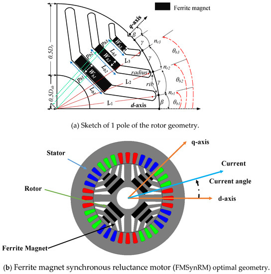
Figure 2.
FMSynRM geometry.
The finite element model (FEM) is constructed using Ansys Maxwell to obtain an optimal design for the motor. A four-pole rotor having three flux barriers per pole with inserted ferrite magnets in the center, see Figure 2, is considered. Three-phase distributed windings are used in the stator. The air gap length is 0.3 mm. The rated speed is 3000 rpm and the target power is 6.5 kW. An optimization technique using the gradient-free Nelder-Mead method is coupled with FEM to select the optimal rotor parameters that achieve the target motor power rating, keeping the torque ripple within the permissible range (<10%). Details of the complete design of FMSynRM is reported in [27]. A sketch of the optimal FMSynRM geometry is shown in Figure 2b.
As mentioned before, the proposed solar pumping system uses the motor inverter to drive the FMSynRM and to increase the solar array output power. Therefore, it is substantial to examine the performance of the designed FMSynRM to control it properly. The FEM based on “Ansys Maxwell” is used to simulate the performance of the FMSynRM.
Figure 3 illustrates the performance of the designed FMSynRM at rated speed (3000 rpm). In this simulation, the motor inverter is emulated by a sinusoidal current supply. Figure 3a displays the change of the FMSynRM output power under different current angles for various winding currents (25–100% of the rated current). The current angle represents the angle between the d-axis and the winding current vector as sketched in Figure 2b. It is clear that the FMSynRM power varies with the current angle; there is a current angle at which the power of the motor is maximum, i.e., called optimal current angle. Further, the optimal current angle value is not a fixed value; it depends on the winding current level due to core saturation. This means that using a fixed current angle is not correct and it results in a reduction in the motor power. Consequently, using the optimal current angle during the control of the motor is important to maximize the motor output power. Moreover, the power of the motor at the rated current and optimal current angle reaches the target motor power for the application (i.e., about 6.5 kW). Figure 3b shows the motor power factor versus the current angle at various winding currents. One can see that the power factor of the designed FMSynRM reaches a unity power factor in contrast to the pure reluctance machines; this is thanks to adding the ferrite magnets. In addition, controlling the FMSynRM to work at the maximum power point reduces the power factor to about 0.8 and 0.78 at 25% and 100% of the rated stator winding current respectively. However, this power factor is still comparable to induction machines. Figure 3c shows the torque ripple variation of the FMSynRM versus the current angle at rated speed (3000 rpm). Notice that, the torque ripple is the difference between the maximum and minimum torque values divided by the average torque value at the given current angle. It is obvious that the torque ripple value is lower than the target value (10%) for winding currents from 50% to 100% of the rated value, which is the most important operating region for the desired application. However, it is slightly higher: up to 16.5% for lower currents. The selection of this optimal motor design is a trade-off between the required target power and torque ripple. Moreover, it is possible to further reduce the torque ripple by skewing the rotor. Figure 3d reports the RMS voltage of the phase winding. The voltage is around 230 V at rated current and optimal current angle.
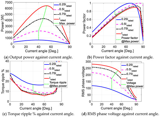
Figure 3.
FMSynRM performance at 3000 rpm.
Figure 4 shows the FMSynRM efficiency map for various speeds and winding currents up to the rated values. It is obvious that the FMSynRM efficiency reaches more than 95%. Besides, the efficiency is about 90% at 30% of the rated power, which proves the wide range of higher efficiency operation of the FMSynRM. Without doubt, this will improve the energy consumption and size of the solar array and therefore, the whole system efficiency will be improved. Figure 5 reports the magnet flux distribution inside the FMSynRM. It is clear that the flux density values inside the tooth and yoke are within the permissible range, i.e., a maximum value of 1.7 T in the tooth based on the magnetization curve of the stator steel.
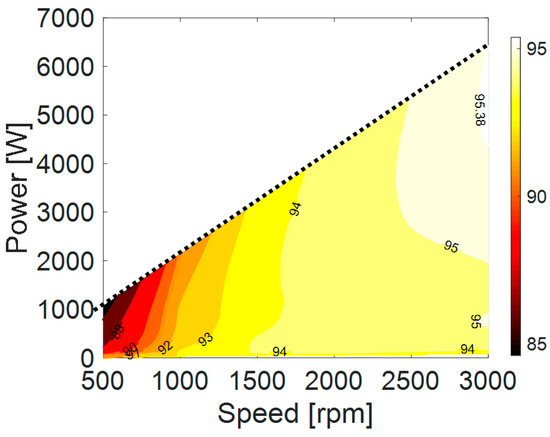
Figure 4.
FMSynRM efficiency map for speeds and winding currents up to the rated values.
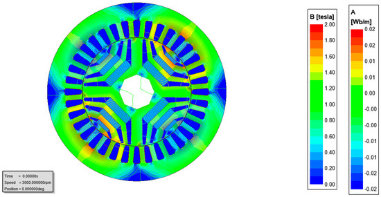
Figure 5.
Flux distribution plot of the FMSynRM.
2.3. Inverter Design
Using the motor output power, efficiency and power factor, the volt–ampere (VA) rating of the inverter can be estimated. A 9 kVA three phase inverter will be used. The inverter DC bus voltage can be computed based on the required motor voltage, taking into account the inverter space vector pulse width modulation constraints in the linear region. Considering the maximum possible RMS phase voltage of the motor (Vmaxrms), which equals 280 V as seen from Figure 3, the minimum DC bus voltage (Vdc) is about 685 V based on (2) [8].
The capacitance of the DC bus capacitor can be estimated based on the DC current (Idc), voltage ripple (ΔVdc) and inverter switching frequency (fPWM) as in (3). It results in a capacitance of about 250 μF [14].
2.4. Solar Array Design
Based on the estimated motor and inverter ratings, it is possible to select the size of the solar array. A solar array of 7.5 kW is selected. The solar module specifications are listed in Table 2 and employed to form the solar array. To achieve the required DC bus voltage, 56 solar modules are connected in series to obtain the required solar array. The voltage and power versus the current of the solar array are reported in Figure 6.
Table 2.
Characteristics of the solar module (KD135SX-UPU).
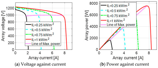
Figure 6.
Solar array characteristics for various irradiation levels at a temperature of 25 °C.
3. Modelling of the Suggested PVWPS
To evaluate the performance of the suggested PVWPS, the complete dynamic mathematical model is necessary. Briefly, the mathematical equations of the various components in the suggested PVWPS is mentioned here [27,28].
3.1. Solar Array
The solar module is simply simulated using a single-diode model. The current-voltage (Iph-Vph) relation of the solar array is represented by [5,6,7,8,9,10]:
where, Vpv, Ipv—array voltage and current respectively; Ns, Np—number of series and parallel modules respectively; Nsc—number of series cells in the module; Rs, Rp—series and parallel resistance respectively; A—diode ideality factor; Iph—photo-current; Vt—thermal voltage; Io—saturation current.
3.2. Voltage Source Inverter Model
The three-phase inverter (VSI) is modelled as follows [30]:
where, van, vbn, vcn—output three-phase voltages; g1, g2, g3—status of the IGBT switches (1 = ON, 0 = OFF); Vdc—DC bus voltage.
3.3. FMSynRM Model
The FMSynRM model is represented in the dq-axis rotor reference frame as follows [30,32]:
where, v, i—voltage and current respectivel; Rm—sator phase resistance; ωr—rotor mechanical speed; P—pole pairs; J, B—the moment of inertia and viscous coefficient of the system respectively; d, q, m—subscripts of direct, quadrature axis and magnet components respectively; Te, TL—motor and load torques respectively; λ, L—flux linkage and inductance respectively.
In synchronous reluctance machines, λd and λq vary nonlinearly with id and iq. Besides, the influence of both currents (id and iq) on the flux linkage in the other axis (λq and λd) is also evident. This means that accurate details about the variation of λd (id, iq) and λq (id, iq) are necessary. To do so, the FEM based on Ansys Maxwell, presented before, is used to generate λd (id, iq) and λq (id, iq) in lookup tables (LUTs), as reported in Figure 7.
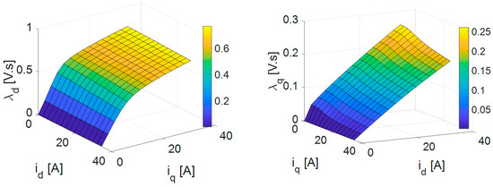
Figure 7.
Flux-linkage components of the FMSynRM against the current components.
3.4. Centrifugal Pump Model
The model of the centrifugal pump is represented by a torque–speed curve using the following relation.
where Kcp is the pump constant and equals 2.065 × 10⁻⁴ N.m/rad/s2.
4. Proposed Control Unit
As mentioned before, the conventional voltage source inverter supplies the motor directly from the solar array. This inverter should be controlled in such a way to do two main tasks: (1) maximizing the output power from the solar array (the magenta dotted line in Figure 6b) and (2) driving the FMSynRM to work at the maximum power per ampere (the green dotted line in Figure 3a). To do those two tasks, the vector control strategy (VCS) is used to control the IGBTs switches of the inverter. The diagram of the VCS is reported in Figure 8. Three proportional-integral (PI) controllers are employed. The controller gains are set by trial and observation method. It is worth noting that only the reference speed signal (ωr*) is used to control the inverter. The speed reference signal (ωr*) controls the motor speed and thus the power flow of the system. Therefore, this signal has to be obtained from the maximum power point tracker (MPPT) of the solar array, see Figure 9.
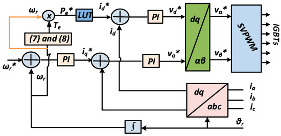
Figure 8.
Diagram of the vector control strategy (VCS).
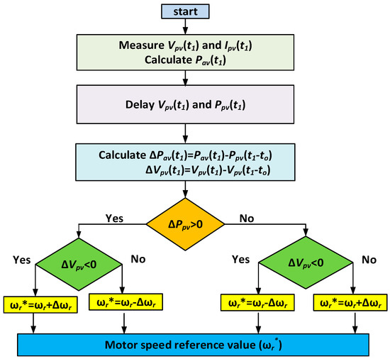
Figure 9.
Main tracking steps of using the perturbation and observation (P&O) technique.
The control system shown in Figure 8 and Figure 9 works in three main steps in a real time as follows.
- Step 1: Measuring the PV voltage and PV current;
- Step 2: Using the perturbation and observation (P&O) tracking method illustrated in Figure 9, the reference speed is increased until the maximum available power of the solar array is reached. At the MPP, there is always an increase and a decrease in the reference speed (ωr*) by Δωr*;
- Step 3: To ensure the FMSynRM operates at the maximum power per ampere, two reference signals are necessary: the speed (ωr*) and the d-axis current (id*). The d-axis current (id*) should be set based on the required power (Pe*) to maximize the maximum power, see Figure 3a. To do so, a lookup table (LUT) between the motor power and the d-axis current is built using FEM (which is validated later on using measurements) and used as in Figure 8.
Consequently, the two main tasks can be realized using the motor inverter.
For demonstration the efficacy of the suggested control system, it is referred to the control scheme presented in [33]. In [33], a real-time assessment of d-axis inductance is carried out to take into account the cross saturation effect for improving the performance of the SynRM. However, accurate online measurements of the inductance requires a well-designed filter to avoid measurement effects e.g., pulse width modulation. In addition, a DC-DC converter is employed to maximize the PV output power using an incremental conductance based tracker. This increases the cost of the system and losses. Moreover, in the simulation work, fixed inductance value is used, which results in a deviation between the simulated and real motor performance due to neglecting the magnetic saturation effect. In contrast, in the proposed system, both simulation and experimental measurements are done using look up tables that correlate the dq-axis flux linkages with the currents (Figure 7) for accurate modelling, as well as the output torque/power of the motor with the reference d-axis current (id*), for accurate control. These look up tables can be built easily and accurately by measurements and also using finite element model of the motor. Moreover, the proposed control system can be implemented using the commercial cheap microcontroller units (MCUs) thanks to the simplicity and less computation required [34].
5. Performance of the Suggested PVPWS
To examine the performance of the suggested PVWPS, the previous mathematical model is built in the MATLAB software package. Here, the inverter switching frequency is 5 kHz. Four different irradiation levels at ambient temperature of 30 °C are assumed, i.e., I = 0.25 kW/m2, II = 0.5 kW/m2, III = 0.75 kW/m2 and IV = 1 kW/m2.
Figure 10 reports the performance of the proposed system. Figure 10a shows the reference and motor speeds at various irradiation levels. It is obvious that the motor speed follows accurately the reference value at all irradiation levels. The motor output power and the pump input power are plotted in Figure 10b. At rated speed (i.e., IV region), the motor output power is similar to the maximum power point at the rated conditions in Figure 3, which proves that the motor is successfully working at the desired point (i.e., maximum power per ampere). This is also evident in Figure 10c,d in which the d and q-axis current components are shown. The d-axis current varies based on the required power to achieve the maximum power per ampere condition and the q-axis current varies to achieve the required power. In addition, here the d and q-axis current components of the motor follow accurately the reference values. Figure 10a,c and d prove that the PI controllers are working properly. Figure 10e shows the solar array output power at the different irradiation levels. Comparing Figure 10e with the solar array characteristics shown in Figure 6, it is evident that the maximum available power of the solar array is successfully extracted. Notice that Figure 6 shows the solar array characteristics at the ambient temperature of 25° C, while Figure 9 considers a practical condition of ambient temperature i.e., 30°. Figure 10f shows the motor efficiency. Interestingly enough, a wide range of high efficiency is evident. The efficiency is more than 92% for low irradiation levels i.e., 0.25 kW/m2 and around 95% for high irradiation levels i.e., 1 kW/m2. This means that the whole system efficiency will be enhanced. Finally, Figure 10g shows the flow rate of the pump.

Figure 10.
Performance of the anticipated PVWPS at ambient temperature of 30 °C and various solar irradiation levels (I = 0.25 kW/m2, II = 0.5 kW/m2, III = 0.75 kW/m2 and IV = 1 kW/m2).
6. Benchmarking of the Proposed System
To benchmark the proposed system compared to a relevant solar PVWPS, a synchronous reluctance motor (SynRM) without ferrite magnet and having identical geometrical specifications as the proposed FMSynRM is used. For a fair comparison, the same MPPT and optimal current angle control strategy as proposed before is implemented. Putting λm = 0 in (4) results in the dynamic mathematical model of the SynRM. Figure 11 reports the performance of the whole system using SynRM at identical conditions as Figure 10. Comparing Figure 10 and Figure 11, it is obvious that the FMSynRM produces about 17.5% and 33% higher power in regions IV and I respectively. This results in about a 29.5% and 15% increase in the flow rate in regions I and IV respectively. Further, the efficiency is also enhanced. It is evident that adding the ferrite magnet improves the performance of the system significantly. The mass of the added ferrite magnets is about 1.85 kg.
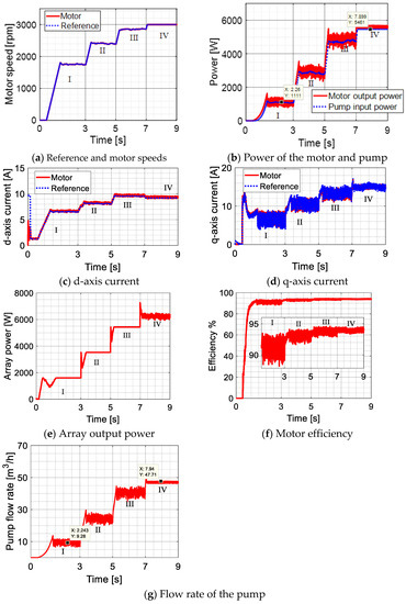
Figure 11.
Performance of the system based on SynRM at ambient temperature of 30 °C and various solar irradiation levels (I = 0.25 kW/m2, II = 0.5 kW/m2, III = 0.75 kW/m2 and IV = 1 kW/m2).
7. Experimental Verification
In order to verify the proposed PVWPS, an experimental laboratory test bench is constructed as illustrated in Figure 12. The test bench includes (1) FMSynRM or SynRM; (2) induction motor (IM) driven by (3) a commercial inverter to emulate the pump characteristics; (4) torque sensor; (5) three-phase inverter to drive the FMSynRM; (6) controlled DC supply; (7) power analyzer; (8) dSpace 1103 connected to PC; and rotor with (9) and without (10) ferrite magnets.
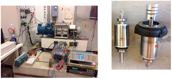
Figure 12.
Experimental test bench.
Figure 13 reports the measured performance of the FMSynRM at rated condition, and validates the simulation results presented in Figure 10 (region IV). A real solar array and pump are not present in the laboratory due to the size and the cost. Instead, a controlled DC supply is used to emulate the solar array characteristics while the induction motor is employed to emulate the centrifugal pump characteristics. The controlled DC supply is used to emulate the solar array characteristics while the induction motor is employed to emulate the centrifugal pump characteristics. The reference speed, which is the output of the MPPT in Figure 9, is given to the control system. It is clear from Figure 13a that the motor speed follows accurately the reference value. The d-and q-axis current components of the motor are shown in Figure 13b,c. The measured motor and load power are shown in Figure 13d. Comparing the measured results of Figure 13 with those obtained by simulation of Figure 10 (region IV), it evident that there is a good correspondence between the theoretical and experimental results.
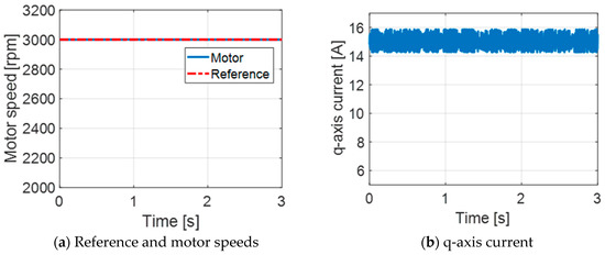
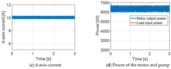
Figure 13.
Measured performance of FMSynRM at rated condition.
Figure 14 shows the measured results of SynRM at rated condition. These results validate the simulated results shown in Figure 11 (region IV). A good match between the theoretical and experimental values is evident. This means that, in the experiments also, the FMSynRM outperforms the conventional SynRM with a higher power of 17.5% in region IV, just as expected from simulations.
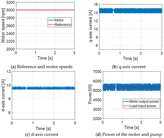
Figure 14.
Measured performance of SynRM at rated condition.
Figure 15 shows the measured and simulated power factor of the motors at various winding currents up to the rated value. The loading condition is represented by the winding current of the motor where the rated load is of course at rated current. It is worth noting that FMSynRM has a high power factor, particularly at low-load cases thanks to the impact of the magnet. Evidently, using FMSynRM in the solar pumping system will improve the inverter size (volt–ampere rating).
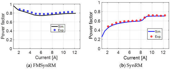
Figure 15.
Measured motor power factor at different currents.
Figure 16 reports the measured efficiency maps of the whole drive system (inverter + motor) of FMSynRM and SynRM at various loading conditions up to the rated value. It is obvious that FMSynRM has a higher efficiency with a wide range compared to SynRM. This corresponds well with those expected by the simulations. However, there is some difference between the measured and simulated efficiencies (about 2% in the motor efficiency) due to mainly neglecting the mechanical and inverter losses in the simulation.
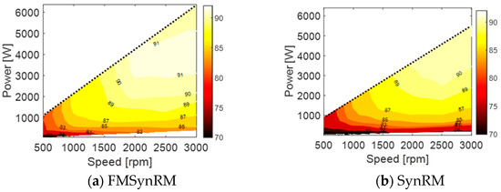
Figure 16.
Measured whole drive (motor + inverter) efficiency map.
8. Conclusions
This paper has presented a novel solar pumping system with improved performance and cost. The proposed system provides a wide range of higher efficiency thanks to using the ferrite magnet synchronous reluctance motor (FMSynRM). In addition, conventional DC-DC converters and batteries are not used, which reduces the system cost and increases the system reliability. The sizing, modeling and performance investigation of the whole system are reported that are applicable to other systems as well, and therefore can be seen as a design methodology. Besides, the performance of the proposed system based on FMSynRM is benchmarked with a similar solar system when a pure SynRM is used. It is shown that the flow rate using the proposed system is increased by about 29.5% at a low irradiation level (0.25 kW/m2) and 15% at a high irradiation level (1 kW/m2) compared to conventional solar system using pure SynRM. This improvement requires only the additional cost of 1.85 kg of cheap ferrite magnets.
Author Contributions
Conceptualization, M.N.I., H.R. and P.S.; methodology, M.N.I., M.A.-D. and H.R.; software, M.N.I.; validation, M.N.I.; resources, M.A.-D. and P.S.; data curation, M.N.I.; writing—original draft preparation, M.N.I. and H.R.; writing—review and editing, M.N.I., H.R., M.A.-D. and P.S.; visualization, M.A.-D.; supervision, M.A.-D. and P.S.; project administration, P.S.; funding acquisition, P.S. All authors have read and agreed to the published version of the manuscript.
Funding
This research received no external funding.
Conflicts of Interest
The authors declare no conflict of interest.
References
- Zavala, V.; López-Luque, R.; Reca, J.; Martínez, J.; Lao, M.T. Optimal management of a multisector standalone direct pumping photovoltaic irrigation system. Appl. Energy 2020, 260, 114261. [Google Scholar] [CrossRef]
- Tyagi, V.V.; Rahim, N.A.A.; Rahim, N.A.; Selvaraj, J.A.L. Progress in solar PV technology: Research and achievement. Renew. Sustain. Energy Rev. 2013, 20, 443–461. [Google Scholar] [CrossRef]
- Periasamy, P.; Jain, N.K.; Singh, I.P. A review on development of photovoltaic water pumping system. Renew. Sustain. Energy Rev. 2015, 43, 918–925. [Google Scholar] [CrossRef]
- López-Luque, R.; Reca, J.; Martínez, J. Optimal design of a standalone direct pumping photovoltaic system for deficit irrigation of olive orchards. Appl. Energy 2015, 149, 13–23. [Google Scholar] [CrossRef]
- Arrouf, M.; Bouguechal, N. Vector control of an induction motor fed by a photovoltaic generator. Appl. Energy 2003, 74, 159–167. [Google Scholar] [CrossRef]
- Sallem, S.; Chaabene, M.; Kamoun, M.B.A. Energy management algorithm for an optimum control of a photovoltaic water pumping system. Appl. Energy 2009, 86, 2671–2680. [Google Scholar] [CrossRef]
- Nabil, M.; Allam, S.M.; Rashad, E.M. Modeling and design considerations of a photovoltaic energy source feeding a synchronous reluctance motor suitable for pumping systems. Ain Shams Eng. J. 2012, 3, 375–382. [Google Scholar] [CrossRef]
- Nabil, M.; Allam, S.M.; Rashad, E.M. Performance improvement of a photovoltaic pumping system using a synchronous reluctance motor. Electr. Power Compon. Syst. 2013, 41, 447–464. [Google Scholar] [CrossRef]
- Ibrahim, M.N.; Rezk, H.; Al-Dahifallah, M.; Sergeant, P. Hybrid photovoltaic-thermoelectric generator powered synchronous reluctance motor for pumping applications. IEEE Access 2019, 7, 146979–146988. [Google Scholar] [CrossRef]
- Miladi, M.; Bennani-Benabdelghani, A.; Slama-Belkhodja, I.; M’Saad, H. An efficient and low-cost single-stage PV pumping system: Experimental investigation based on standard frequency converter. Int. J. Renew. Energy Res. 2018, 8, 108119. [Google Scholar]
- Vitorino, M.A.; Correa, M.B.R. High performance photovoltaic pumping system using induction motor. In Proceedings of the 2009 Brazilian Power Electronics Conference, Bonito-Mato Grosso do Sul, Brazil, 28 September–2 October 2009; pp. 797–804. [Google Scholar]
- Raju, A.B.; Kanik, S.R.; Jyoti, R. Maximum efficiency operation of a single stage inverter fed induction motor PV water pumping system. In Proceedings of the First International Conference on Emerging Trends in Engineering and Technology, Nagpur, Maharashtra, India, 16–18 July 2008; pp. 905–910. [Google Scholar]
- Caracas, J.V.M.; Farias, G.d.C.; Teixeira, L.F.M.; Ribeiro, L.A.d.S. Implementation of a high-efficiency, high-lifetime, and low-cost converter for an autonomous photovoltaic water pumping system. IEEE Trans. Ind. Appl. 2014, 50, 631–641. [Google Scholar] [CrossRef]
- Shukla, S.; Singh, B. Single-stage PV array fed speed sensorless vector control of induction motor drive for water pumping. IEEE Trans. Ind. Appl. 2018, 54, 3575–3585. [Google Scholar] [CrossRef]
- Singh, B.; Shukla, S. Induction motor drive for PV water pumping with reduced sensors. IET Power Electron. 2018, 11, 1903–1913. [Google Scholar] [CrossRef]
- Inoue, S.; Shimomura, S.; Morimoto, M. Loss evaluation on induction machines made with soft magnetic composite. In Proceedings of the 15th International Conference on Electrical Machines and Systems (ICEMS), Sapporo, Japan, 21–24 October 2012; pp. 1–6. [Google Scholar]
- Murshid, S.; Singh, B. Reduced sensor based PMSM driven autonomous solar water pumping system. IEEE Trans. Sustain. Energy 2020, 11, 1323–1331. [Google Scholar] [CrossRef]
- Singh, B.; Murshid, S. A grid-interactive permanent-magnet synchronous motor-driven solar water-pumping system. IEEE Trans. Ind. Appl. 2018, 54, 5549–5561. [Google Scholar] [CrossRef]
- Kumar, R.; Singh, B. Single stage solar PV fed brushless DC motor driven water pump. IEEE J. Emerg. Sel. Top. Power Electron. 2017, 5, 1377–1385. [Google Scholar] [CrossRef]
- Karbakhsh, F.; Amiri, M.; Zarchi, H.A. Two-switch flyback inverter employing a current sensorless MPPT and scalar control for low cost solar powered pumps. IET Renew. Power Gen. 2017, 11, 669–677. [Google Scholar] [CrossRef]
- Packiam, P.; Jain, N.K.; Singh, I.P. Steady and transient characteristics of a single stage PV water pumping system. Energy Syst. 2015, 6, 173–199. [Google Scholar] [CrossRef]
- Murshid, S.; Singh, B. Simulation and hardware implementation of PMSM driven solar water pumping system. In Proceedings of the 2018 International Conference on Power, Instrumentation, Control and Computing (PICC), Thrissur, India, 18–20 January 2018; pp. 1–6. [Google Scholar]
- Mishra, A.K.; Singh, B. Self-governing single-stage photovoltaic water pumping system with voltage balancing control for a four-phase SRM drive. IET Electr. Power Appl. 2020, 14, 119–130. [Google Scholar] [CrossRef]
- Ibrahim, M.N.; Sergeant, P.; Rashad, E.M. Design of low cost and efficient photovoltaic pumping system utilizing synchronous reluctance motor. In Proceedings of the IEEE International Electric Machines and Drives Conference (IEMDC), Miami, FL, USA, 21–24 May 2017; pp. 1–7. [Google Scholar]
- Ibrahim, M.N.; Rezk, H.; Al-Dhaifallah, M.; Sergeant, P. Solar array fed synchronous reluctance motor driven water pump: An improved performance under partial shading conditions. IEEE Access 2019, 7, 77100–77115. [Google Scholar] [CrossRef]
- Bonthu, S.S.R.; Islam, M.Z.; Choi, S. Performance review of permanent magnet assisted synchronous reluctance traction motor designs. In Proceedings of the IEEE Energy Conversion Congress and Exposition (ECCE), Portland, OR, USA, 23–27 September 2018; pp. 1682–1687. [Google Scholar]
- Bonthu, S.S.R.; Arafat, A.; Choi, S. Comparisons of rare-earth and rare-earth-free external rotor permanent magnet assisted synchronous reluctance motors. IEEE Trans. Ind. Electron. 2017, 64, 9729–9738. [Google Scholar] [CrossRef]
- Vartanian, R.; Toliyat, H.A. Design and comparison of an optimized permanent magnet-assisted synchronous reluctance motor (PMa-SynRM) with an induction motor with identical NEMA Frame stators. In Proceedings of the IEEE Electric Ship Technologies Symposium, Baltimore, MD, USA, 20–22 April 2009; pp. 107–112. [Google Scholar]
- Prieto, D.; Dagusé, B.; Dessante, P.; Vannier, J. Performance comparison of the permanent magnet assisted synchronous reluctance motor and the double magnet synchronous motor. In Proceedings of the 15th European Conference on Power Electronics and Applications (EPE), Lille, France, 2–6 September 2013; pp. 1–7. [Google Scholar]
- Ibrahim, M.N. Design Aspects of High Performance Synchronous Reluctance Machines with and without Permanent Magnets. Ph.D. Thesis, Ghent University, Gent, Belgium, 2017. [Google Scholar]
- Ma, Q.; El-Refaie, A.; Lequesne, B. Low-cost interior permanent magnet machine with a blend of magnet types. In Proceedings of the IEEE International Electric Machines & Drives Conference (IEMDC), San Diego, CA, USA, 12–15 May 2019; pp. 1303–1310. [Google Scholar]
- Ibrahim, M.N.; Sergeant, P.; Rashad, E.M. Relevance of including saturation and position dependence in the inductances for accurate dynamic modeling and control of SynRMs. IEEE Trans. Ind. Appl. 2017, 53, 151–160. [Google Scholar] [CrossRef]
- Varshney, A.; Sharma, U.; Singh, B. Adaptive d-axis current control of RSyM for photovoltaic water pumping incorporating cross saturation. IEEE Trans. Ind. Inform. 2020, 16, 6487–6498. [Google Scholar] [CrossRef]
- Packiam, P.; Jain, N.K.; Singh, I.P. Microcontroller-based simple maximum power point tracking controller for single-stage solar stand-alone water pumping system. Prog. Photovolt. 2013, 21, 462–471. [Google Scholar] [CrossRef]
© 2020 by the authors. Licensee MDPI, Basel, Switzerland. This article is an open access article distributed under the terms and conditions of the Creative Commons Attribution (CC BY) license (http://creativecommons.org/licenses/by/4.0/).