Article

Electrostatic Capacity of a Metallic Cylinder: Effect of the Moment Method Discretization Process on the Performances of the Krylov Subspace Techniques

1
Dipartimento di Ingegneria Civile Energia Ambiente e Materiali, “Mediterranea” University, Via Graziella Feo di Vito, I-89122 Reggio Calabria, Italy
2
Dipartimento di Ingegneria dell’Informazione Infrastrutture Energia Sostenibile, “Mediterranea” University, Via Graziella Feo di Vito, I-89122 Reggio Calabria, Italy
*
Author to whom correspondence should be addressed.
Mathematics 2020, 8(9), 1431; https://doi.org/10.3390/math8091431
Submission received: 5 August 2020 / Revised: 20 August 2020 / Accepted: 24 August 2020 / Published: 26 August 2020

Abstract

:
When a straight cylindrical conductor of finite length is electrostatically charged, its electrostatic potential ϕ depends on the electrostatic charge q e , as expressed by the equation L ( q e ) = ϕ , where L is an integral operator. Method of moments (MoM) is an excellent candidate for solving L ( q e ) = ϕ numerically. In fact, considering q e as a piece-wise constant over the length of the conductor, it can be expressed as a finite series of weighted basis functions, q e = n = 1 N α n f n (with weights α n and N, number of the subsections of the conductor) defined in the L domain so that ϕ becomes a finite sum of integrals from which, considering testing functions suitably combined with the basis functions, one obtains an algebraic system L m n α n = g m with dense matrix, equivalent to L ( q e ) = ϕ . Once solved, the linear algebraic system gets α n and therefore q e is obtainable so that the electrostatic capacitance C = q e / V , where V is the external electrical tension applied, can give the corresponding electrostatic capacitance. In this paper, a comparison was made among some Krylov subspace method-based procedures to solve L m n α n = g m . These methods have, as a basic idea, the projection of a problem related to a matrix A R n × n , having a number of non-null elements of the order of n, in a subspace of lower order. This reduces the computational complexity of the algorithms for solving linear algebraic systems in which the matrix is dense. Five cases were identified to determine L m n according to the type of basis-testing functions pair used. In particular: (1) pulse function as the basis function and delta function as the testing function; (2) pulse function as the basis function as well as testing function; (3) triangular function as the basis function and delta function as the testing function; (4) triangular function as the basis function and pulse function as the testing function; (5) triangular function as the basis function with the Galerkin Procedure. Therefore, five L m n and five pair q e and C were computed. For each case, for the resolution of L m n α n = g m obtained, GMRES, CGS, and BicGStab algorithms (based on Krylov subspaces approach) were implemented in the MatLab® Toolbox to evaluate q e and C as N increases, highlighting asymptotical behaviors of the procedures. Then, a particular value for N is obtained, exploiting both the conditioning number of L m n and considerations on C, to avoid instability phenomena. The performances of the exploited procedures have been evaluated in terms of convergence speed and CPU-times as the length/diameter and N increase. The results show the superiority of BcGStab, compared to the other procedures used, since even if the number of iterations increases significantly, the CPU-time decreases (more than 50%) when the asymptotic behavior of all the procedures is in place. This superiority is much more evident when the CPU-time of BicGStab is compared with that achieved by exploiting Gauss elimination and Gauss–Seidel approaches.

1. Introduction

As it is well known, electrostatic problems are classified according to the equations that describe them. These equations could be differential (ordinary or partial derivative), integral, or both. Most electrostatic problems can be represented by an abstract equation [1,2]
L F = h
in which L is an operator (differential, integral, or integro-differential), h is the known excitation or source, and F is the unknown function to be determined. For solving the problem (1), it is usually transformed into an equivalent algebraic problem
L α = g ,
in which L is an algebraic matrix [2,3,4]. As it is well known, modern computers have created the conditions for developing numerical resolution methods for a wide class of problems lacking an analytical solution. Among them is the MoM which, initially introduced by Harrington [1,2], solves (1), transforming it into an equivalent algebraic formulation.
With this aim, the unknown is expanded using a known set of functions (the basis functions), and Equation (1) is then projected on another set of functions (the testing functions). The basis functions can be the same as the testing functions (Galerkin method) or chosen differently. Specifically, the choice of basis and testing functions determine, on the one hand, the formulation of the elements of the algebraic matrix L and, on the other, influences the speed of convergence of the methods employed to solve (2) [3,5]. However, the MoM transforms (1) into (2), where L is usually dense [1,3,6,7].
With this purpose, the MoM has been used with excellent results [8,9,10]. Specifically, the pulse and delta functions, respectively, as the basis and testing functions, have been used to solve (1) according to the observation that the choice of the basis and testing functions substantially influences the desired level of accuracy [1,11,12].
The scientific literature is rich concerning the study of q e distributions and C computations through the MoM in which different basis and testing functions are exploited [10,13,14,15,16,17,18,19]. For example, in [14], related to a single cylindrical conductor, the q e distribution was studied, and the C were studied when different basis and testing functions were exploited (pulse, delta, triangular functions). However, in these works, the solutions were obtained by exploiting only direct techniques for solving the (2) [17,19].
In this paper, starting from [14], the problem of the distribution of q e on a cylindrical metallic conductor of finite length as well as the calculation of the related C was addressed when an external electric voltage V was applied. In particular, once the geometry of the problem was defined and the source and observation points fixed, the problem was formulated in terms of electrostatic potential ϕ by means of an integral formulation. Then, the basis and testing functions were defined and q e developed in terms of a finite set of basis functions f n , n = 1 , , N ,
q e = n = 1 N α n f n ,
with weights α n . Applying the MoM, ϕ provides an equation with unknown N. However, choosing N points of independent observations on the surface of the conductor, we arrive at a formulation of N × N algebraic system
L m n α n = g m
in which the elements of the dense matrix L m n , characterized by integral formulations, depend on the choice of basis and testing functions f n and w m , with n = 1 , , N and m = 1 , , N and g m depending on w m . The following five pairs of basis and testing functions were used: pulse and delta functions; pulse and pulse functions; triangular and delta functions (point matching); triangular and pulse functions; and triangular and triangular functions. Once the five dense matrices L were obtained (one for each pair of basis and testing function) by means of the MoM application, the corresponding linear algebraic systems were solved by using different Krylov subspaces methods because they are the most suitable for solving algebraic problems such as (2) in which L is dense and characterized by a large dimension [20,21,22,23]. In the past, Krylov subspaces have been widely exploited in both theoretical and applied areas. In particular, in mathematics, excellent works have been produced through the application of Krylov subspaces for solving sparse linear systems [21,23], for solving sequences of linear systems [24], and for obtaining the solution in quadratic-bilinear differential systems [25,26]. Furthermore, excellent works have been produced by applying the Krylov subspace for the resolution of sequences of non-linear structural problems [27] and for the topological problems of optimization [28]. Finally, the interest of a lot of researches focused on the Krylov subspaces for linear infinite-dimensional systems [29]. In the physical domain, Krylov subspaces have been exploited for solving a lot important equations such as the Dirac equation [30] and problems with matrix exponential operators [31]. Moreover, several works exploiting Krylov subspaces have been produced for solving practical problems. For example, in the chemical domain, preconditioned Krylov subspaces methods have been applied to evaluate the variational density [32,33]. On the other hand, in engineering, in particular, electromagnetics, many papers have been published concerning Krylov subspaces [34,35]. In particular, many efforts have been made to solve integral equations for scattering electromagnetic fields [36], for solving a class of tensor equations [37], and for large Lyapunov equations [38]. Moreover, even in the theory of electrical circuits, Krylov subspaces have been applied to obtain good performance in terms of simulations [39,40]. Although the scientific literature in the electromagnetic field is very rich in works in which Krylov subspaces have been successfully used, it lacks information regarding the application of Krylov subspaces for the computation of the electric charge and electrostatic capacity on electrical conductors. This is mainly due to the fact that in the literature, the calculation of these parameters often takes place through the usual solvers of linear systems since online computing was often not required. However, nowadays, real-time applications are increasingly frequent so that the usual solvers of linear systems do not offer high performances in terms of time-saving. Therefore, it is now essential to use solvers with computational complexity compatible with the times of real-time applications. In this context, the idea of the present work matures, which aims to compute the distribution of both electrostatic charge and capacity of conductors subjected to an external potential difference V using the methods based on Krylov subspaces, which notoriously offer computational complexity compared to the usual solver [21,23].
In this work, the generalized minimal residual method (GMRES), conjugate gradient squared (CGS) and biconjugate gradient stabilized (BicGStab) techniques have been implemented on an Intel Core 2 CPU 1.45 GHz machine and MatLab ® R2017a, to solve the linear systems with dense matrix obtained by the MoM application to the electrostatic problem mentioned above to evaluate their performances by calculating the time consumed and the number of necessary iterations. Finally, the comparison was carried out both with two usual solution techniques for linear algebraic systems (Gauss elimination and Gauss–Seidel). The results obtained highlighted the superiority of the BicGStab procedure compared to the other approaches used. In particular, as the size of the problem increases, the number of iterations required by BicGStab, compared to the other procedures used, increases, but the CPU-time considerably reduces. Specifically, the highest CPU-time obtained with BicGStab (25.9 s) is less than (a) 46.1% of the highest CPU-time obtained with the CGS procedure (48.0254 s); (b) 27.91% of the highest CPU-time obtained with the GMRES procedure (35.92 s); (c) 81.93% of the highest CPU-time obtained with Gauss elimination (143.34 s), and (d) 93.1% of CPU-time detected with the Gauss-Seidel procedure (377.7439 s). Finally, since L in all studied cases is ill-conditioned, this suggests the need to consider and develop suitable pre-conditioners.
The remaining part of the paper is structured as follows: Section 2 describes the electrostatic problem under study: once the geometry of the conductor is defined (Section 2.1), the formulation of the electrostatic problem is detailed in Section 2.2. Section 3 offers a brief overview of the MoM to transform (1) into (2) and presents the sets of functions exploited as basis functions and testing ones. Section 4 develops the expansion of the electrostatic charge density in terms of basis functions and formulates the algebraic matrix following the MoM approach. Section 4.1, Section 4.2, Section 4.3, Section 4.4 and Section 4.5 show how the individual elements of the algebraic matrix can be obtained when different pairs of basis and testing functions are exploited. Then, once the algebraic systems are obtained, Section 5 offers a detailed overview of the Krylov subspace approach for solving high-dimensional linear systems. Again, Section 5.2, Section 5.3, Section 5.4, Section 5.5, Section 5.6, Section 5.7 and Section 5.8 describe the characteristics of each procedure exploited in this work and based on Krylov subspaces. The most significant numerical results are described and commented in detail in Section 6. Finally, some conclusive observations and possible future developments conclude the work (see Section 7).

2. The Electrostatic Problem

2.1. Geometry

Let us consider a system of Cartesian axes O x y z wherein the x axis is represented by the longitudinal symmetry axis of a cylindrical conductor occupying a region of R 3 ( Ω is the source region).
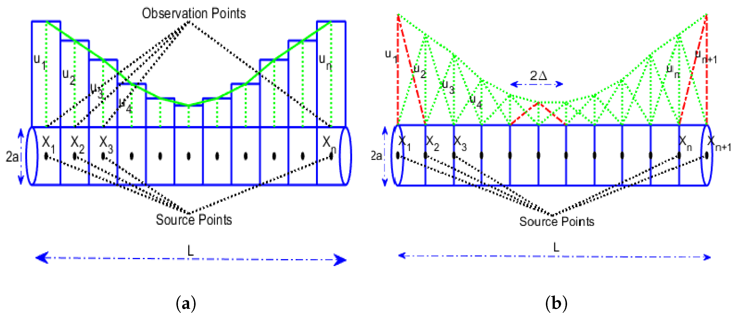
As shown in Figure 1, a cylindrical circular conductor is characterized by the length L ¯ and radius a. On the surface (plane x z ) are located the observation points pointed by r = ( x , 0 , a ) , while the source points, on axis x, are pointed by r = ( x , 0 , 0 ) so that | r r | = ( x x ) 2 + a 2 0 .

2.2. Formulation

As known, the electrostatic potential ϕ ( x ) , computed at any point r due to any electrostatic charge q e located at r (see Figure 1), can be written as [1,2,5].
ϕ ( x ) = Ω 1 4 π ϵ q e ( x ) | r r | d Ω = Ω 1 4 π ϵ q e ( x ) ( x x ) 2 + a 2 d Ω .
Remark 1.
If we know q e , we can compute the electric potential everywhere. Instead, if we know the electric potential but not the q e , Equation (5) becomes an integral equation as L ( q e ( x ) ) = ϕ ( x ) for an unknown charge density so that L is an integral operator. Then, the problem must be solved numerically. The MoM is an excellent candidate for solving L ( q e ( x ) ) = ϕ ( x ) numerically [5,6].

3. The Method of Moments: A Brief Overview

3.1. Backgrounds

Once (1) is obtained, the procedure for applying the MoM involves the following three steps:
  • the first step involves discretization of (1) into a matrix equation exploiting basis functions (or expansions) and weighting functions (or testing);
  • the evaluation of the matrix elements is obtained;
  • the matrix equation is solved to obtain the parameters of interest.
Concerning the expansions of f, a series of functions f n defined in the L domain are considered so that
f n = 1 N α n f n
where the α n are the constants to be determined. We will call f n the basis functions or expansion functions.
Remark 2.
To obtain the exact solution from (6), it is necessary to use an infinite sum and choose f n ( x ) as a complete set of basic functions. However, we will consider (6) with a finite summation, without being bound to choose a complete system for f n ( x ) . On the other hand, f n ( x ) must be linearly independent and chosen so that (6) approximates f ( x ) .
Substituting (6) into L f = g , we get
g L n = 1 N α n f n = n = 1 N α n L ( f n )
where the residual R is
R = g n = 1 N α n L ( f n ) .
We introduce a series of weighting functions (also called testing functions), w 1 , w 2 , ..., w N , in the range of L and, assuming a suitable internal product of L f n ( x ) with w m , define it as follows:
Definition 1.
[Inner Product or Moment] Let us define an inner product or moment between a basis function f n ( r ) and a testing or weighting function w m ( r ) as follows:
< w m , f n > = w m w m ( r ) · f n f n ( r ) d r d r
in which the integral is surface, volume, or line depending on both the basis and testing functions.
It is required that the inner product of each w m with the residual function be zero so that
n = 1 N α n < w m , L ( f n ) > < w m , g >
which results in the N × N matrix with element < w m , L ( f n ) > . Then, the system can be matricially written as follows:
[ L m n ] [ α n ] = [ g m ]
in which
[ L m n ] = < w 1 , L ( f 1 ) > < w 1 , L ( f 2 ) > < w 2 , L ( f 1 ) > < w 2 , L ( f 2 ) > , [ α n ] = α 1 α 2 , [ g m ] = < w 1 , g > < w 2 , g > .
Obviously, if [ L m n ] is not singular, then the unknowns α n are as follows:
[ α n ] = [ L m n ] 1 [ g m ] ,
in order that f ( x ) can be reconstructed by Equation (6).
Remark 3.
Usually, L is a large matrix so that the usual methods (direct or iterative) for solving linear algebraic systems struggle to obtain the solution in a reasonable time, requiring the use of alternative procedures for solving (13). The procedures for solving linear systems based on Krylov subspaces are a valid alternative to the classic resolution methods, as they ensure reduced computation times even in the presence of large matrices [21,23].

3.2. Point Matching

We applied the boundary conditions by testing the integral equation in a series of discrete points on the conductor. This is equivalent to using a delta function as a weighting function w m ( r ) = Δ ( r ) . This procedure (point matching or point collocation), in evaluating the elements of the matrix, does not require any integral in the range of the test function but only that related to the pulse function. However, the boundary conditions are met only in discrete locations across the domain of the solution, allowing it to assume a different value at points other than those used for testing.

3.3. Galerkin Procedure

The choice of the testing function is decisive for obtaining a good solution. According to the Galerkin approach, basis functions can also be used as testing functions with the definite advantage of applying the boundary conditions in the whole domain of the solution than in discrete points.
Remark 4.
It is worth noting that, as in the following, Galerkin testing refers to a testing procedure where the set of testing functions is the same as the set of basis functions. However, in this work, even when the same type of functions are used as basis and testing functions, the sets are different since the testing functions are translated with respect to the basis functions. Thus, in this work, Galerkin testing is not used. Then, we shall use the term “pseudo-Galerking procedure”.

3.4. The Set of Functions

3.4.1. Pulse Functions

Dividing the domain into N + 1 points with N sections, the Pulse function is defined as follows:
f n ( x ) = 1 x n x x n + 1 ; f n ( x ) = 0 elsewhere .
The pulse functions represent a simple approximation of the solution on each section (Figure 2a). However, they can only simplify the computation of the elements of the matrix L . Since the derivative of the pulse functions is the delta function Δ , they cannot be used when L contains a derivative with respect to x.

3.4.2. Delta Function

As known
Δ ( x ) = singular if x = 0 ; Δ ( x ) = 0 elsewhere .
It is worth noting that Δ ( x ) is not a function but it represents a distribution.

3.4.3. Piecewise Triangular Functions

Triangular functions, unlike the pulse functions, extend over two adjacent segments and vary from zero in the external points while it is equal to the unit in the center (Figure 2b). Specifically, dividing the domain into N + 1 points and N sections will result in an N 1 triangular basis function. Generally, a triangular function is defined as follows:
f n ( x ) = x x n 1 x n x n 1 ; x n 1 x x n f n ( x ) = x n + 1 x x n + 1 x n x n x x n + 1 .
These functions can also be used when L contains derivatives with respect to x.

4. The [ L mn ] Formulations

Let us divide the conductor into N N sections with length Δ x valuable as Δ x = L N . In addition, let us consider N + 1 points x m = m Δ x , m = 1 , 2 , , N at the ends of each section so that Ω = [ 0 , L ] . We highlight that within each section, the charge density has a constant value. Then, q e ( x ) is the piece-wise constant over the length of the conductor. Therefore, according to (6), we write the following:
q e ( x ) = n = 1 N α n f n ( x )
Hence, substituting (17) into (5), we obtain
ϕ ( x ) = Ω 1 4 π ϵ q e ( x ) ( x x ) 2 + a 2 d x = 1 4 π ϵ n = 1 N α n ( n 1 ) Δ x n Δ x f n ( x ) ( x x ) 2 + a 2 d x
from which
4 π ϵ ϕ ( x ) = α 1 0 Δ x f 1 ( x ) ( x x ) 2 + a 2 d x + α 2 Δ x 2 Δ x f 2 ( x ) ( x x ) 2 + a 2 d x + + + α N 1 ( N 2 ) Δ x ( N 1 ) Δ x f N 1 ( x ) ( x x ) 2 + a 2 d x + α N ( N 1 ) Δ x N Δ x f N ( x ) ( x x ) 2 + a 2 d x .
Equation (19) defines an equation in N unknowns. To solve it, we must obtain N equations in N unknowns. Then, we need to choose N independent observation points x m on the surface of the conductor (each one at the center of a conductor section). Therefore, if the boundary condition is ϕ = V = constant, we write the following:
4 π ϵ V = α 1 0 Δ x f 1 ( x ) ( x 1 x ) 2 + a 2 d x + + α N ( N 1 ) Δ x N Δ x f N ( x ) ( x 1 x ) 2 + a 2 d x 4 π ϵ V = α 1 0 Δ x f 1 ( x ) ( x N x ) 2 + a 2 d x + + α N ( N 1 ) Δ x N Δ x f N ( x ) ( x N x ) 2 + a 2 d x
which represents a system in the form (11). In addition, according to (9), the local weighted average is formed on each x m by exploiting a local testing function w m , which is centered at x m so that the system (20), with m = 1 , , N , can be rewritten, if V is not constant on x, in the following way:
4 π ϵ 0 Δ x w 1 ( x ) V ( x ) d x = = α 1 0 Δ x ( m 1 ) Δ x m Δ x w 1 ( x ) · f 1 ( x ) ( x 1 x ) 2 + a 2 d x d x + + α N 0 Δ x ( m 1 ) Δ x m Δ x w 1 ( x ) · f N ( x ) ( x 1 x ) 2 + a 2 d x d x 4 π ϵ ( N 1 ) Δ x N Δ x w N ( x ) V ( x ) d x = = α 1 0 Δ x w N ( x ) · f 1 ( x ) ( x N x ) 2 + a 2 d x + + α N ( N 1 ) Δ x N Δ x w N ( x ) · f N ( x ) ( x N x ) 2 + a 2 d x
in which the individual elements L m n and the vector g m are, respectively,
L m n = ( n 1 ) Δ x n Δ x ( m 1 ) Δ x m Δ x w m ( x ) · f n ( x ) ( x m x ) 2 + a 2 d x d x
g m = 4 π ϵ ( m 1 ) Δ x m Δ x w m ( x ) V ( x ) d x .
Remark 5.
Once q e is obtained by (17), C is easy to compute as follows:
C = q e V .
In this work, the approach described above will be applied to exploit the following sets of basis and weighting functions:
  • In the first case, we present the study carried out that exploits the pulse function as the basis function, and as the testing function, the delta function will be considered as required in the point-matching approach;
  • In the second case, following the pseudo-Galerkin procedure, the pulse function will be exploited as the basis function as well as the testing function;
  • In the third case, the triangular function will be exploited as the basis function, while the delta function will be exploited as the testing function (point-matching approach);
  • In the fourth case, the triangular function will be considered the basis function while the pulse function will be exploited as the testing function;
  • Finally, in the fifth case, the triangular function will be considered the basis function as well as the testing function according to the pseudo-Galerkin approach.

4.1. First Case: Pulse Function as Basis Function and Delta Function as Testing Function (Point Matching)

Taking into account the pulse function defined in Section 4.5 (see Figure 2a) and the delta function defined in Section 3.4.2, the individual elements L m n , according to (22), can be easily written as follows:
L m n = ( n 1 ) Δ x n Δ x 1 ( x m x ) 2 + a 2 d x .
After the numerical integration of (25), the following expression is determined [14]:
L m n = log ( x n + 1 x m ) + ( x n + 1 x m ) 2 a 2 ( x n 1 x m ) + ( x n x m ) 2 a 2 ,
in which x n + 1 = x n + Δ x and x n 1 = x n Δ x . Thus, according to (23), g m can be written as
g m = V m = 4 π ϵ ( m 1 ) Δ x m Δ x Δ ( x ) V ( x ) d x = 4 π ϵ V .
Therefore, by means of (13), we obtain α n so that q e ( x ) can be computed, exploiting (17). Finally, exploiting (24), the electrostatic capacity C is easily evaluated.

4.2. Second Case: Pulse Function as Basis Function as well as Testing Function

Exploiting the pulse function as the basis and testing functions as well, the individual elements L m n , according to (22), can be easily computed as follows:
L m n = ( n 1 ) Δ x n Δ x ( m 1 ) Δ x m Δ x f n ( x x ) · f m ( x x ) ( x x ) 2 + a 2 d x d x .
After performing the integration, we obtain [14]:
L m n = ( x m + 1 x n + 1 ) 2 a 2 + ( x m + 1 x n + 1 ) · log x m + 1 x n + 1 a 2 x m + 1 + x n + 1 ( x m x n + 1 ) 2 a 2 ( x m x n + 1 ) · log ( x m x n + 1 ) 2 a 2 x m + x n + 1 ( x m + 1 x n 1 ) 2 a 2 ( x m + 1 x n 1 ) · log ( x m + 1 x n 1 ) 2 a 2 x m + 1 + x n 1 + + ( x m 1 x n 1 ) 2 a 2 + ( x m 1 + x n 1 ) · log ( x m 1 x n 1 ) 2 a 2 x m 1 + x n 1 .
in which x n + 1 = x n + Δ x , x n 1 = x n Δ x , x m + 1 = x m + Δ x and x m 1 = x m Δ x . Then, g m , as required in (23), becomes
g m = V m = 4 π ϵ ( m 1 ) Δ x m Δ x f m ( x x ) V ( x ) d x = 4 π ϵ Δ x V
in which f m ( x x ) is defined as in Section 4.5. Further, in this case, by exploiting (13), we easily obtain α n , from which q e ( x ) is evaluable by means of (17). Finally, exploiting (24), C is easily obtainable.

4.3. Third Case: Triangular Function as Basis Function and Delta Function as Testing Function (Point Matching)

The triangular function spans over two adjacent sections and varies from 0 at the corner points of the section to 1 at the centre point of the section. Obviously, the function overlaps by one section so that the triangles give a piece-wise linear variation of the solution among sections (see Figure 2b).
Remark 6.
When the basis function is the triangular function, q e ( x ) expansion becomes
q e ( x ) = n = 1 N N α n f n ( x )
with f n ( x ) defined as described in Section 3.4.3. Moreover, the charge distribution along the conductor, when the triangular basis functions are considered, has a span of 2 Δ x (twice as long as the Pulse case).
The cylindrical conductor, in this case, is divided into N sections whose width is e Δ x = L / N and N + 1 points, x m = m Δ x , located at the end points of these sections (see Figure 2b). Obviously, the basis function at the first and last sections must be a half triangle because the charge density at the edges shoots up. For the triangular function as the basis function and the delta function as the testing function, the individual elements L m n , according to (22), become:
L m n = x n 1 x n x x n 1 Δ x 1 ( x m x ) 2 + a 2 d x + x n x n + 1 x n + 1 x Δ x 1 ( x m x ) 2 + a 2 d x .
After performing the integration of (32), L m n assumes the following form [14]:
L m n = x n + 1 Δ x log a 2 + ( x n + 1 x m ) 2 + x n + 1 x m a 2 + ( x n x m ) 2 + x n x m x n 1 Δ x log a 2 + ( x n x m ) 2 + x n x m a 2 + ( x n 1 x m ) 2 + x n 1 x m 1 Δ x x m a 2 + ( x n + 1 x m ) 2 log ( 2 ( a 2 + ( x n + 1 x m ) 2 + x n + 1 x m ) ) + a 2 + ( x n + 1 x m ) 2 a 2 + ( x n + 1 x m ) 2 1 Δ x x m a 2 + ( x n 1 x m ) 2 log ( 2 ( a 2 + ( x n 1 x m ) 2 + x n 1 x m ) ) + a 2 + ( x n 1 x m ) 2 a 2 + ( x n 1 x m ) 2 + + 2 Δ x x m a 2 + ( x n x m ) 2 log ( 2 ( a 2 + ( x n x m ) 2 + x n x m ) ) + a 2 + ( x n x m ) 2 a 2 + ( x n x m ) 2
in which, as usual, x n + 1 = x n + Δ x and x n 1 = x n Δ x . Finally, as required in (23), g m becomes
g m = V m = 4 π ϵ V .
As explained in the previous sections, exploiting (13), we determine α n so that q e ( x ) , by means of (17), is computable. Therefore, by (24), C is computed.

4.4. Fourth Case: Triangular Function as Basis Function and Pulse Function as Testing Function

In this case, the expression provided by (22) is integrated considering the pulse testing function and replacing x m with x on which the integration is performed. The expression for the individual L m n can be written in the following compact form:
L m n = x n + 1 Δ x ( A 1 m n A 2 m n ) x n 1 Δ x ( A 2 m n A 3 m n ) 1 Δ x A 4 m n 1 Δ x A 5 m n + 2 Δ x A 6 m n
in which A i m n , for i = 1 , 2 , , 6 , are computed as follows [14]:
A 1 m n = a 2 + ( x m + 1 x n + 1 ) 2 a 2 + ( x m 1 x n + 1 ) 2 + + log a 2 + ( x m + 1 x n + 1 ) 2 x m + 1 + x n + 1 ( x m + 1 x n + 1 ) a 2 + ( x m 1 x n + 1 ) 2 x m 1 + x n + 1 ( x m 1 x n + 1 )
A 2 m n = a 2 + ( x m + 1 x n ) 2 a 2 + ( x m 1 x n ) 2 + + log a 2 + ( x m + 1 x n ) 2 x m + 1 + x n ( x m + 1 x n ) a 2 + ( x m 1 x n ) 2 x m 1 + x n ( x m 1 x n )
A 3 m n = a 2 + ( x m + 1 x n 1 ) 2 a 2 + ( x m 1 x n 1 ) 2 + + log a 2 + ( x m + 1 x n 1 ) 2 x m + 1 + x n 1 ( x m + 1 x n 1 ) a 2 + ( x m 1 x n 1 ) 2 x m 1 + x n 1 ( x m 1 x n 1 )
A 4 m n = 1 2 log a 2 + ( x m + 1 x n + 1 ) 2 x m + 1 + x n + 1 ( x m + 1 2 x n + 1 2 ) a 2 + ( x m 1 x n + 1 ) 2 x m 1 + x n + 1 ( x m 1 2 x n + 1 2 ) + + 1 4 ( 3 x m + 1 + x n + 1 ) a 2 + ( x m + 1 x n + 1 ) 2 1 4 ( 3 x m 1 + x n + 1 ) a 2 + ( x m 1 x n + 1 ) 2 + + a 2 4 log a 2 + ( x m + 1 x n + 1 ) 2 + x m + 1 x n + 1 a 2 + ( x m 1 x n + 1 ) 2 + x m 1 x n + 1
A 5 m n = 1 2 log a 2 + ( x m + 1 x n 1 ) 2 x m + 1 + x n 1 ( x m + 1 2 x n 1 2 ) a 2 + ( x m 1 x n 1 ) 2 x m 1 + x n 1 ( x m 1 2 x n 1 2 ) + + 1 4 ( 3 x m + 1 + x n 1 ) a 2 + ( x m + 1 x n 1 ) 2 1 4 ( 3 x m 1 + x n 1 ) a 2 + ( x m 1 x n 1 ) 2 + + a 2 4 log a 2 + ( x m + 1 x n 1 ) 2 + x m + 1 x n 1 a 2 + ( x m 1 x n 1 ) 2 + x m 1 x n 1
A 6 m n = 1 2 log a 2 + ( x m + 1 x n ) 2 x m + 1 + x n ( x m + 1 2 x n 2 ) a 2 + ( x m 1 x n ) 2 x m 1 + x n ( x m 1 2 x n 2 ) + + 1 4 ( 3 x m + 1 + x n ) a 2 + ( x m + 1 x n ) 2 1 4 ( 3 x m 1 + x n ) a 2 + ( x m 1 x n ) 2 + + a 2 4 log a 2 + ( x m + 1 x n ) 2 + x m + 1 x n a 2 + ( x m 1 x n ) 2 + x m 1 x n
where x m + 1 = x m + Δ x and x m 1 = x m Δ x . Therefore, g m is given by
g m = V m = 4 π ϵ Δ x V
and, as usual, by (13), we obtain α n so that q e ( x ) , exploiting (17), is carried out. Finally, by (24), C is computed.

4.5. Fifth Case: Triangular Function as a Basis Function with the Galerkin Procedure

In the last case, the individual L m n is determined as follows:
L m n = x n 1 x n x m 1 x m x x n 1 Δ x x x m 1 Δ x d x d x a 2 + ( x x ) 2 + + x n x n + 1 x m x m + 1 x n + 1 x Δ x x m + 1 x Δ x d x d x a 2 + ( x x ) 2 .
The integration of (43) is quite complicated. However, after long mathematical steps, it is possible to express it in in the following compact form:
L m n = A m n B m n C m n + D m n ,
where
A m n = x n + 1 ( Δ x ) 2 ( A 1 m n A 2 m n ) x n 1 ( Δ x ) 2 ( A 2 m n A 3 m n ) 1 ( Δ x ) 2 ( A 4 m n A 5 m n ) + 2 ( Δ x ) 2 A 6 m n ,
B m n = x n + 1 ( Δ x ) 2 ( B 1 m n B 2 m n ) x n 1 ( Δ x ) 2 ( B 2 m n B 3 m n ) 1 ( Δ x ) 2 ( B 4 m n B 5 m n ) + 2 ( Δ x ) 2 B 6 m n ,
C m n = x m 1 x n + 1 ( Δ x ) 2 ( C 1 m n C 2 m n ) x m 1 x n 1 ( Δ x ) 2 ( C 2 m n C 3 m n ) x m 1 ( Δ x ) 2 ( C 4 m n + C 5 m n C 6 m n )
D m n = x m 1 x n + 1 ( Δ x ) 2 ( D 1 m n D 2 m n ) x m 1 x n 1 ( Δ x ) 2 ( D 2 m n D 3 m n ) x m + 1 ( Δ x ) 2 ( D 4 m n + D 5 m n D 6 m n ) .
Each term in (45)–(48) is specifiable as follows:
A 1 m n = 1 4 ( x m + 3 x n + 1 ) a 2 + ( x m x n + 1 ) 2 1 4 a 2 log a 2 + ( x m x n + 1 ) 2 + x m x n + 1 a 2 + ( x m 1 + x n + 1 ) 2 + x m 1 x n + 1 + + 1 2 ( x m 2 x n + 1 2 ) log a 2 + ( x m x n + 1 ) x m + x n + 1 1 4 ( x m 1 + 3 x n + 1 ) a 2 + ( x m 1 x n + 1 ) 2 1 2 ( x m 1 2 x n + 1 2 ) log a 2 + ( x m 1 x n + 1 ) 2 x m 1 + x n + 1
A 2 m n = 1 4 ( x m + 3 x n ) a 2 + ( x m x n ) 2 1 4 a 2 log a 2 + ( x m x n ) 2 + x m x n a 2 + ( x m 1 + x n ) 2 + x m 1 x n + + 1 2 ( x m 2 x n 2 ) log a 2 + ( x m x n ) x m + x n 1 4 ( x m 1 + 3 x n ) a 2 + ( x m 1 x n ) 2 1 2 ( x m 1 2 x n 2 ) log a 2 + ( x m 1 x n ) 2 x m 1 + x n
A 3 m n = 1 4 ( x m + 3 x n 1 ) a 2 + ( x m x n 1 ) 2 1 4 a 2 log a 2 + ( x m x n 1 ) 2 + x m x n + 1 a 2 + ( x m 1 + x n 1 ) 2 + x m 1 x n 1 + + 1 2 ( x m 2 x n 1 2 ) log a 2 + ( x m x n 1 ) x m + x n 1 1 4 ( x m 1 + 3 x n 1 ) a 2 + ( x m 1 x n 1 ) 2 1 2 ( x m 1 2 x n 1 2 ) log a 2 + ( x m 1 x n 1 ) 2 x m 1 + x n 1
A 4 m n = 1 3 log ( a 2 + ( x m x n + 1 ) 2 x m + x n + 1 ) ( x m 3 x n + 1 3 ) ( a 2 + ( x m 1 x n + 1 ) 2 x m 1 + x n + 1 ) ( x m 1 3 x n + 1 3 ) + 1 9 a 2 + ( x m x n + 1 ) 2 · ( a 2 + 4 x m 2 + x m x n + 1 + 4 x n + 1 2 ) 1 9 a 2 + ( x m 1 x n + 1 ) 2 ( a 2 + 4 x m 1 2 + x m 1 x n + 1 + 4 x n + 1 2 )
A 5 m n = 1 3 log ( a 2 + ( x m x n 1 ) 2 x m + x n 1 ) ( x m 3 x n 1 3 ) ( a 2 + ( x m 1 x n 1 ) 2 x m 1 + x n 1 ) ( x m 1 3 x n 1 3 ) + + 1 9 a 2 + ( x m x n 1 ) 2 · ( a 2 + 4 x m 2 + x m x n 1 + 4 x n 1 2 ) 1 9 a 2 + ( x m 1 x n 1 ) 2 ( a 2 + 4 x m 1 2 + x m 1 x n 1 + 4 x n 1 2 )
A 6 m n = 1 3 log ( a 2 + ( x m x n ) 2 x m + x n ) ( x m 3 x n 3 ) ( a 2 + ( x m 1 x n ) 2 x m 1 + x n ) ( x m 1 3 x n 3 ) + 1 9 a 2 + ( x m x n ) 2 · ( a 2 + 4 x m 2 + x m x n + 4 x n 2 ) 1 9 a 2 + ( x m 1 x n ) 2 ( a 2 + 4 x m 1 2 + x m 1 x n + 4 x n 2 )
B 1 m n = 1 4 ( x m + 1 + 3 x n + 1 ) a 2 + ( x m + 1 x n + 1 ) 2 1 4 a 2 log a 2 + ( x m + 1 x n + 1 ) 2 + x m + 1 x n + 1 a 2 + ( x m + x n + 1 ) 2 + x m x n + 1 + + 1 2 ( x m + 1 2 x n + 1 2 ) log a 2 + ( x m + 1 x n + 1 ) x m + 1 + x n + 1 1 4 ( x m + 3 x n + 1 ) a 2 + ( x m x n + 1 ) 2 1 2 ( x m 2 x n + 1 2 ) log a 2 + ( x m x n + 1 ) 2 x m + x n + 1
B 2 m n = 1 4 ( x m + 3 x n ) a 2 + ( x m x n ) 2 1 4 a 2 log a 2 + ( x m x n ) 2 + x m x n a 2 + ( x m 1 + x n ) 2 + x m 1 x n + + 1 2 ( x m 2 x n 2 ) log a 2 + ( x m x n ) x m + x n 1 4 ( x m 1 + 3 x n ) a 2 + ( x m 1 x n ) 2 1 2 ( x m 1 2 x n 2 ) log a 2 + ( x m 1 x n ) 2 x m 1 + x n
B 3 m n = 1 4 ( x m + 1 + 3 x n 1 ) a 2 + ( x m + 1 x n 1 ) 2 1 4 a 2 · log a 2 + ( x m + 1 x n 1 ) 2 + x m + 1 x n + 1 a 2 + ( x m + x n 1 ) 2 + x m x n 1 + + 1 2 ( x m + 1 2 x n 1 2 ) · log a 2 + ( x m + 1 x n 1 ) x m + 1 + x n 1 1 4 ( x m + 3 x n 1 ) a 2 + ( x m x n 1 ) 2 1 2 ( x m 2 x n 1 2 ) log a 2 + ( x m x n 1 ) 2 x m + x n 1
B 4 m n = 1 3 log ( a 2 + ( x m + 1 x n + 1 ) 2 x m + 1 + x n + 1 ) ( x m + 1 3 x n + 1 3 ) ( a 2 + ( x m x n + 1 ) 2 x m + x n + 1 ) ( x m 3 x n + 1 3 ) + + 1 9 a 2 + ( x m + 1 x n + 1 ) 2 · ( a 2 + 4 x m + 1 2 + x m + 1 x n + 1 + 4 x n + 1 2 ) 1 9 a 2 + ( x m x n + 1 ) 2 ( a 2 + 4 x m 2 + x m x n + 1 + 4 x n + 1 2 )
B 5 m n = 1 3 log ( a 2 + ( x m + 1 x n 1 ) 2 x m + 1 + x n 1 ) ( x + 1 m 3 x n 1 3 ) ( a 2 + ( x m x n 1 ) 2 x m + x n 1 ) ( x m 3 x n 1 3 ) + + 1 9 a 2 + ( x m + 1 x n 1 ) 2 · ( a 2 + 4 x m + 1 2 + x m + 1 x n 1 + 4 x n 1 2 ) 1 9 a 2 + ( x m x n 1 ) 2 ( a 2 + 4 x m 2 + x m x n 1 + 4 x n 1 2 )
B 6 m n = 1 3 log ( a 2 + ( x m + 1 x n ) 2 x m + 1 + x n ) ( x m + 1 3 x n 3 ) ( a 2 + ( x m x n ) 2 x m + x n ) ( x m 3 x n 3 ) + + 1 9 a 2 + ( x m + 1 x n ) 2 · ( a 2 + 4 x m + 1 2 + x m + 1 x n + 4 x n 2 ) 1 9 a 2 + ( x m x n ) 2 ( a 2 + 4 x m 2 + x m x n + 4 x n 2 )
C 1 m n = a 2 + ( x m x n + 1 ) 2 a 2 + ( x m 1 x n + 1 ) 2 + + log ( a 2 + ( x m x n + 1 ) 2 x m + x n + 1 ) ( x m x n + 1 ) ( a 2 + ( x m 1 x n + 1 ) 2 x m 1 + x n + 1 ) ( x m 1 x n + 1 )
C 2 m n = a 2 + ( x m x n ) 2 a 2 + ( x m 1 x n ) 2 + + log ( a 2 + ( x m x n ) 2 x m + x n ) ( x m x n ) ( a 2 + ( x m 1 x n ) 2 x m 1 + x n ) ( x m 1 x n )
C 3 m n = a 2 + ( x m x n 1 ) 2 a 2 + ( x m 1 x n 1 ) 2 + + log ( a 2 + ( x m x n 1 ) 2 x m + x n 1 ) ( x m x n 1 ) ( a 2 + ( x m 1 x n 1 ) 2 x m 1 + x n 1 ) ( x m 1 x n 1 )
C 4 m n = 1 2 log ( a 2 + ( x m x n + 1 ) 2 x m + x n + 1 ) ( x m 2 x n + 1 2 ) ( a 2 + ( x m 1 x n + 1 ) 2 x m 1 + x n + 1 ) ( x m 1 2 x n + 1 2 ) + + 1 4 ( 3 x m + x n + 1 ) a 2 + ( x m x n + 1 ) 2 1 4 ( 3 x m 1 + x n + 1 ) a 2 + ( x m 1 x n + 1 ) 2 + + a 2 4 log a 2 ( x m x n + 1 ) 2 + x m x n + 1 a 2 + ( x m 1 x n + 1 ) 2 + x m 1 x n + 1
C 5 m n = 1 2 log ( a 2 + ( x m x n 1 ) 2 x m + x n 1 ) ( x m 2 x n 1 2 ) ( a 2 + ( x m 1 x n 1 ) 2 x m 1 + x n 1 ) ( x m 1 2 x n 1 2 ) + + 1 4 ( 3 x m + x n 1 ) a 2 + ( x m x n 1 ) 2 1 4 ( 3 x m 1 + x n 1 ) a 2 + ( x m 1 x n 1 ) 2 + + a 2 4 log a 2 ( x m x n 1 ) 2 + x m x n 1 a 2 + ( x m 1 x n 1 ) 2 + x m 1 x n 1
C 6 m n = 1 2 log ( a 2 + ( x m x n ) 2 x m + x n 1 ) ( x m 2 x n 2 ) ( a 2 + ( x m 1 x n ) 2 x m 1 + x n ) ( x m 1 2 x n 2 ) + + 1 4 ( 3 x m + x n ) a 2 + ( x m x n ) 2 1 4 ( 3 x m 1 + x n ) a 2 + ( x m 1 x n ) 2 + + a 2 4 log a 2 ( x m x n ) 2 + x m x n a 2 + ( x m 1 x n ) 2 + x m 1 x n .
D 1 m n = a 2 + ( x m + 1 x n + 1 ) 2 a 2 + ( x m x n + 1 ) 2 + + log ( a 2 + ( x m + 1 x n + 1 ) 2 x m + 1 + x n + 1 ) ( x m + 1 x n + 1 ) ( a 2 + ( x m x n + 1 ) 2 x m + x n + 1 ) ( x m x n + 1 )
D 2 m n = a 2 + ( x m + 1 x n ) 2 a 2 + ( x m x n ) 2 + + log ( a 2 + ( x m + 1 x n ) 2 x m + 1 + x n ) ( x m + 1 x n ) ( a 2 + ( x m x n ) 2 x m + x n ) ( x m x n )
D 3 m n = a 2 + ( x m + 1 x n 1 ) 2 a 2 + ( x m x n 1 ) 2 + + log ( a 2 + ( x m + 1 x n 1 ) 2 x m + 1 + x n 1 ) ( x m + 1 x n 1 ) ( a 2 + ( x m x n 1 ) 2 x m + x n 1 ) ( x m x n 1 )
D 4 m n = 1 2 log ( a 2 + ( x m + 1 x n + 1 ) 2 x m + 1 + x n + 1 ) ( x m + 1 2 x n + 1 2 ) ( a 2 + ( x m x n + 1 ) 2 x m + x n + 1 ) ( x m 2 x n + 1 2 ) + + 1 4 ( 3 x m + 1 + x n + 1 ) a 2 + ( x m + 1 x n + 1 ) 2 1 4 ( 3 x m + x n + 1 ) a 2 + ( x m x n + 1 ) 2 + + a 2 4 log a 2 ( x m + 1 x n + 1 ) 2 + x m + 1 x n + 1 a 2 + ( x m x n + 1 ) 2 + x m x n + 1
D 5 m n = 1 2 log ( a 2 + ( x m + 1 x n 1 ) 2 x m + 1 + x n 1 ) ( x m + 1 2 x n 1 2 ) ( a 2 + ( x m x n 1 ) 2 x m + x n 1 ) ( x m 2 x n 1 2 ) + + 1 4 ( 3 x m + 1 + x n 1 ) a 2 + ( x m + 1 x n 1 ) 2 1 4 ( 3 x m + x n 1 ) a 2 + ( x m x n 1 ) 2 + + a 2 4 log a 2 ( x m + 1 x n 1 ) 2 + x m + 1 x n 1 a 2 + ( x m x n 1 ) 2 + x m x n 1
D 6 m n = 1 2 log ( a 2 + ( x m + 1 x n ) 2 x m + 1 + x n 1 ) ( x m + 1 2 x n 2 ) ( a 2 + ( x m x n ) 2 x m + x n ) ( x m 2 x n 2 ) + + 1 4 ( 3 x m + 1 + x n ) a 2 + ( x m + 1 x n ) 2 1 4 ( 3 x m + x n ) a 2 + ( x m x n ) 2 + + a 2 4 log a 2 ( x m + 1 x n ) 2 + x m + 1 x n a 2 + ( x m x n ) 2 + x m x n .
As usual, x n + 1 = x n + Δ x , x n 1 = x n Δ x , x m + 1 = x m + Δ x and x m 1 = x m Δ x . Finally, g m is computed as
g m = V m = 4 π ϵ V x m 1 x m x x m 1 Δ x d x + x m x m + 1 x m + 1 x Δ x d x
so that, after integration, we obtain
g m = V m = 4 π ϵ Δ x V x m 2 x m 1 2 2 x m + 1 2 2 x m 1 ( x m x m 1 ) + x m + 1 ( x m + 1 x m ) .
Therefore, once g m is determined, by means of (13), we carry out α n so that q e ( x ) , exploiting (17), is computable. Finally, by (24), C is computed.
Remark 7.
As previously noted, whatever the basis function and the chosen test functions, the modeling of the problem under study leads to the formulation of the linear algebraic problem (11) whose resolution is imperative for the calculation of the electrostatic charge density (and therefore electrostatic capacity). The usual resolution methods, direct (such as the Gauss elimination method) or iterative (such as the Gauss–Seidel method), although applicable in all the cases studied, do not take into account the fact that the matrix L is large with high dimensions. Therefore, we will focus on some methods of solving large linear systems based on Krylov subspaces.

5. High-Dimension Linear Systems Resolution: A Krylov Subspaces Approach

5.1. Iterations in Krylov Subspaces

Definition 2.
Let us consider A R N × N and b R N . For r = 1 , 2 , , we define the Krylov subspace with index r generated by A and b , the set
K r : = s p a n ( b , A b , A 2 b , , A r 1 b ) R N .
Projection methods in Krylov subspaces consist of projecting a problem of size N into a smaller Krylov subspace [21,23]. They then determine, for each r, an approximate solution x ( r ) of the linear system A x = b , which belongs to the subspace K r . Krylov methods can be divided into four different classes that lead to different algorithms and that represent the different optimality criteria to choose the vector x ( r ) :
(1)
Ritz–Galerkin approach: construct the vector x ( k ) such that the corresponding residual is orthogonal to the Krylov sub-space with index k, i.e.,
b A x ( k ) K r ;
(2)
The residual minimum norm approach: identify x ( k ) for which the Euclidean residual norm b A x ( k ) 2 is minimum on K r ;
(3)
Petrov–Galerkin approach: find x ( k ) such that b A x ( k ) is orthogonal to some subspace of size k;
(4)
The least norm error approach: determine
x ( k ) A T K k ( A T , b )
(Krylov subspace with index k generated by A T and b ) so the Euclidean norm of error x ( k ) x 2 is minimal.
It has been observed that these optimality criteria lead to different algorithms; in particular, the Ritz–Galerkin approach can lead to the conjugate gradient and Lanczos methods. The second approach leads to the meetings of generalized minimal residual (GMRES) and minimal residual (MINRES). However, these two approaches have the disadvantage of being very slow, especially in the case of non-symmetric systems, and computationally expensive to determine the approximate solution. Moreover, this problem is solved by considering other subspaces for the orthogonal condition (as in the Petrov-Galerkin method). The third approach leads to the bi-conjugate gradient (Bi-CG) and quasi-minimal residual (QMR) methods while the fourth is not immediate, but for A = A T , it leads to the symmetric LQ (SYMMLQ) method. To identify the approximation x ( l ) of the solution, it is necessary to determine a basis for the Krylov subspace of index l, which can be extended to subspaces of increasing size.
Remark 8.
We observe that the basis for the Krylov subspace l-dimensional K l is
{ b , A b , A 2 b , , A l 1 b } .
This base turns out to be numerically unstable because as l increases, the vectors A l b tend to dominate the eigen vector and therefore tend to be linearly independent. One could think of considering this base non-orthogonal and orthogonalize it later, but this could lead to strong ill-conditioning. The problem, therefore, arises in replacing this unstable base with an orthogonal or orthonormal base that characterizes the Krylov procedure used.

5.2. Conjugate Gradient (CG) as Krylov Method

It is possible to demonstrate that the CG method is characterized by an iteration in Krylov subspaces and therefore can be considered as a Krylov method [21,23]. In fact, the following theorem holds:
Theorem 1.
Let us suppose to apply the CG method to the linear system A x = b , with A symmetrical and positive defined. If the initial vector is x ( 0 ) = 0 , then the method proceeds until the residue r ( k ) is canceled and the following identities hold, for l = 1 , , k , for the Krylov subspaces:
K l : = s p a n ( b , A b , , A l 1 b ) = s p a n ( x ( 1 ) , , x ( l ) ) = = s p a n ( p ( 0 ) , , p ( l 1 ) ) = s p a n ( r ( 0 ) , , r ( l 1 ) ) .
Furthermore, the residuals are orthogonal for every l ( r ( t ) ) T r ( j ) = 0 , j = 0 , 1 , , l 1 and the research directions are A-conjugated, ( p ( l ) ) T A p ( l ) = 0 , j = 0 , 1 , , l 1 .
As can be seen from Theorem 1, the CG method constitutes the base of K l numerically unstable (78) with the base constituted by the A-orthogonal directions { p ( 0 ) , , p ( l 1 ) } .
Let us introduce the following definition:
Definition 3.
Under the assumption that A is a symmetric and definite positive matrix, and therefore, the eigenvalues of A are all positive or equivalently x T A x 0 for each vector x R N not null, the function · A defined by
· A = x T A x
is the so-called A n o r m .
It can, therefore, be shown that the generic iteration x ( l ) of the CG method has an important optimality property. The following result holds:
Theorem 2.
The vector x ( l ) minimizes in Krylov subspace K l the A-norm of the error, i.e., it turns out that
x ( l ) = arg min x K l x * x A ,
where x * is the exact solution of the linear system. Moreover, if
e ( l ) = x * x ( l )
then we have
e ( l ) A e ( l 1 ) A , l .

5.3. The Arnoldi Method

The Arnoldi Iteration

The Arnoldi method is a Krylov subspace projection method for non-Hermitian matrices. This procedure, introduced as a method for reducing a dense matrix in the form of Hessenberg, allows to obtain a matrix factorization. Arnoldi iteration allows us to build a base { q 1 , , q l } for the Krylov subspace K l consisting of vectors orthonormal to each other, replacing the numerically unstable base (78). This can be done by applying the Gram–Schmidt orthogonalization method, obtaining a factorization of A R N × N in the form
A Q l = Q l + 1 H ^ l ,
where
Q l R N × l , | l + 1 R N × ( l + 1 )
and H ^ l R ( l + 1 ) × l . The procedure can be summarized in the following steps:
  • The algorithm starts by means of an arbitrary vector q 1 whose norm is 1;
  • For k = 2 , 3 , q k = A q k 1 ; in addition, for j = 1 , , k 1
    h j , k 1 = q j * q k
    and
    q k = q k h j , k q j ;
  • Then,
    h k , k 1 = q k
    and
    q k = q k h k , k 1 .
  • The algorithm breaks down when q k is a null vector or, alternatively, each of its components is less than a fixed tolerance. This occurs when the minimal polynomial of A is of degree k.
Remark 9.
It is worth noting that the j-loop projects the components of q k on the directions of q 1 , , q k 1 ensuring the orthogonality of all the generated vectors.

5.4. GMRES Method

This method consists of iteratively constructing an orthonormal base, through the Arnoldi method, for the Krylov space K l , with l = 1 , , n , approximating at each step the solution of the system x * with the vector x ( l ) K l to minimize the 2-norm of the residual r ( l ) = b A x ( l ) . Practically, if we set
x ( l ) = arg min x K l b A x 2 ,
the solution is projected into the Krylov K l subspace and is determined by solving a least squares problem. We observe that for the properties of the Arnoldi iteration, the method, in many cases, makes it possible to obtain a sufficiently accurate approximation of the system solution in a number of steps much lower than N, despite being a method that ends in at most N steps. Let us see how we proceed in an operational way, remembering that the matrix in the form of Hessenberg
H l = Q l T A Q l
is the representation in the orthonormal base q 1 , , q l of the orthogonal projection A on the K l subspace. In fact, taking a generic vector y R l , the product Q l y expresses a generic vector of K l as a linear combination of the elements of the orthonormal base considered. Therefore, one has
b A x = A Q l y b .
Taking into account that A Q k = Q k + 1 H ^ k , we can write
A Q l y b = Q l + 1 H ^ l y b ,
from which, being Q l + 1 T Q l + 1 = I l + 1 and observing that Q l + 1 T b = b e 1 , we obtain
b A x = H ^ l y b e 1 .
Thus, to solve the least squares problem x ( l ) = arg min x K l b A x 2 , it is possible to calculate the solution y ( l ) of the minimization problem
min y R l H ^ l y b e 1 ,
and calculate x ( l ) = Q l y ( l ) .
Remark 10.
The cost of the algorithm is that due to the Arnoldi method. Furthermore, it should be noted that to calculate a new solution, it is necessary to memorize all the vectors of the base. Hence, the GMRES procedure becomes too expensive and inefficient if the size of the Krylov subspace grows too much. A possible solution to the problem is represented by restarting. It consists of stopping the algorithm when a certain size m of the Krylov subspace is reached; we then calculate x m and start again with the algorithm with initial approximation x m above. Furthermore, it is worth noting that restarting while increasing the number of iterations considerably reduces the CPU-time.

5.5. The Biconjugate Gradient Method (BiCG)

CG is not suitable for non-symmetric systems because the residual vectors cannot be made orthogonal with short recurrences [21,23]. While the GMRES method preserves the orthogonality of the residues by exploiting extensive occurrences with a large storage demand, the BiCG procedure replaces the orthogonal sequence of the residues with two further mutually-orthogonal sequences without the need for minimization [23]. Together with the orthogonal residuals generated by the CG procedure, the BiCG method constructs a second set of residuals in which the initial residual can be chosen without particular constraints. Thus, the BiCG procedure requires two matrix-by-vector products by A and by A T . The residuals form biorthogonal bases. Moreover, the corresponding direction form biconjugate bases. Regarding convergence, the BiCG method provides the same results as the CG method when positive defined systems are considered but with a considerable increase in the computational cost for each iteration. If the matrices are not symmetrical in cases where there is a significant reduction in the residual norm, the BiCG method is comparable, in terms of the number of iterations, with the GMRES method. Furthermore, the convergence can be irregular and the procedure could face breakdown phenomena which, among other things, can be avoided by means of appropriate restart operations.
Remark 11.
However, it is not always guaranteed that restarting the BiCG procedure improves performance; in fact, while GMRES is guaranteed to converge in n steps, it is not ensured that the method is not subject to stagnation using this technique.
Remark 12.
To compare the performances obtained with the GMRES and BiCG is difficult. While GMRES minimizes a residue by increasing the work to keep all the orthogonal residues with a consequent increase in the demand for space in memory, the BiCG method does not minimize any residue, but its precision is comparable to that obtained with the GMRES method at the cost of twice the quantity of matrix products per vector for each iteration. However, no special memory efforts are required to generate the base vectors because this procedure is based on the Lanczos biorthogonalization cheaper from the point of view of memory demand than the orthogonalization of Arnoldi [21,23].
To increase the effectiveness of the BiCG method, several variants have been proposed, including the CGS and the BiCGStab methods.

5.6. The CGS Method

This approach, proposed by Sonneveld [23], replaces the multiplication with A T in BiCG by a second one with A and writes the residual by a square polynomial [21,23]. At each iteration, the dimension of the Krylov subspace is increased by two units. Concerning the convergence, it is almost twice as fast as BiCG, but even more erratic. If the computation with A T is impractical, CGS may be attractive.
Remark 13.
Increase in rounding errors and possible overflow could take place. This occurrence leads to a preference for the BiCStab method.

5.7. The BicGStab Method

Developed by Van der Vorst [21,23], this method avoids the often irregular convergence of CGS by means of combining the CGS sequence with the steepest descent update, performing some local optimization and smoothing. The procedure is based on writing the residual by a product between two polynomials and formally constituted by the following steps:
(1)
Firstly, we compute r 0 : = b A x 0 ;
(2)
Then, we set p 0 : = r 0 ;
(3)
For j = 0 , 1 , until convergence we compute the following quantities
α j = ( r j , r 0 ) ( A p j , r 0 ) ; s j = r j α j A p j ; ω j = ( A s j , s j ) ( A s j , A s j ) ; x j + 1 = x j + α j p j + ω j s j ; r j + 1 = s j ω j A s j ; β j = ( r j + 1 , r 0 * ) ( r j , r 0 ) α j ω j ; p j + 1 = r j + 1 + β j ( p j ω j A p j ) .

5.8. Comparison between GMRES and BicGStab

It is not generally possible to say which of the two methods is more efficient. However, it is possible to formulate the following hypothesis: as the number of elements in the matrix decreases, the BicGStab algorithm should be faster. In fact, although there are two matrix-carrier products in BiCGStab, these should have a limited cost in relation to the products performed many times and to the high storage cost of GMRES. The time taken by the BicGStab algorithm is almost always shorter. However, the GMRES algorithm performs fewer iterations (despite taking longer) than the BicGStab algorithm as the number of non-zero elements increases. Finally, to influence the computational cost of the GMRES algorithm, in addition to the products performed a large number of times, it could be the high number of elements that must be stored.
Remark 14.
It is worth noting that the matrices are often ill-conditioned. A pre-condition must therefore exist: the results depend very much on the accuracy of the pre-condition.

6. Numerical Results

L m n have been computed by (26), (29), (33), (35), and (44) exploiting, as described above, pulse–delta, pulse–pulse, triangular–delta, triangular–pulse, and triangular–triangular basis-testing functions, respectively. Once the matrix L was formed, the corresponding linear system was solved by GMRES, CGS, and BicGStab procedures, comparing the results with those determined by Gauss elimination and Gauss–Seidel methods to obtain the unknown q e on each section of the conductor. Then, substituting the value of charge density from Equation (13) and the basis function, as described in Section 4.5 or Section 3.4.3, into Equations (17) and (24), q e and C are obtained. The following remark justifies the use of the Gauss–Seidel iterative procedure.
Remark 15.
We observe that the Gauss–Seidel iterative method is applicable in our cases because all the matrices L m n are all with dominant diagonal by rows. In other words:
| L i i | > j = 1 , j i n | L i j | .
This condition implies the non-singularity of the matrices, from which follows the uniqueness of the solution [23].

6.1. Results Concerning the Values of Capacitance C & Instability Phenomena

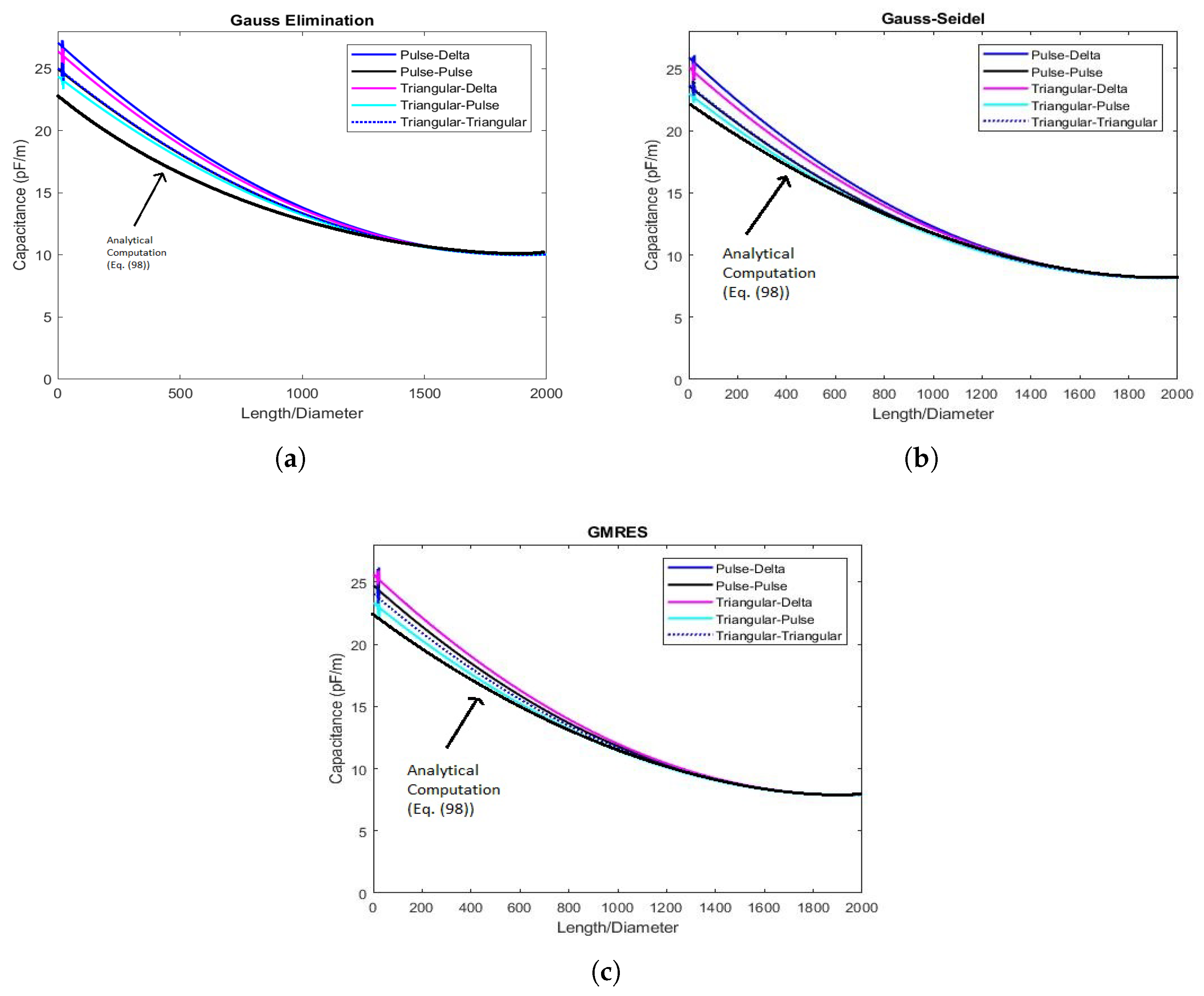
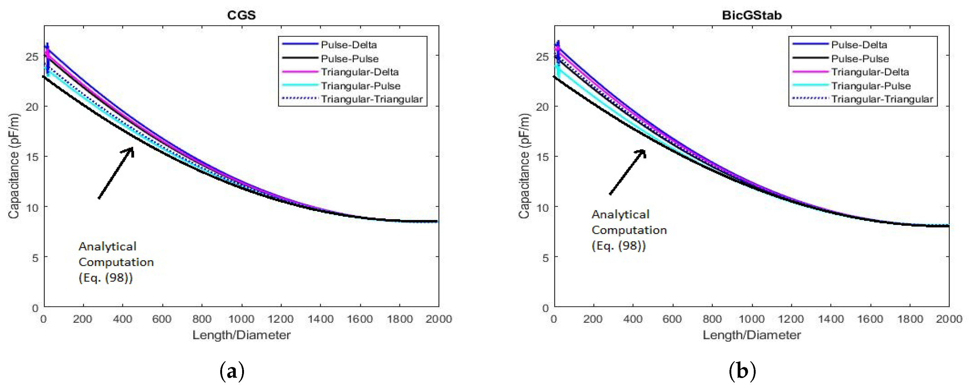
The numerical values obtained for C for unit length (using different basis and testing functions) exploiting the above-mentioned procedures are displayed in Figure 3a–c and Figure 4a,b, respectively. The trends highlight that C, for each procedure applied, assumes regular behavior when L ¯ d < 20 while a slight instability occurs when 20 < L ¯ d < 40 . This is due to the fact that the distribution of q e on the conductor generates an electric dipole vector p which forms an angle θ with the electric field vector E . It is proven that when θ 0 instabilities occur until θ , due to the forces generated by E , becomes null. This condition of instability occurs when 20 < L ¯ d < 40 [2]. When L ¯ d < 20 and L ¯ d > 40 , p and E are almost parallel for which the instability is extremely reduced. However, the instability displayed in each simulation has a limited amplitude and it is such as not to cause concern.
However, it is worth noting that whatever the numerical procedure used to solve the dense linear system and whatever the basis-testing functions pair, for high values of the L ¯ / d ratio, C tends to assume the same value. This is due to the fact that for increasing L ¯ / d , the mesh becomes denser, and therefore, asymptotically, the numerical procedures applied provide the same results.
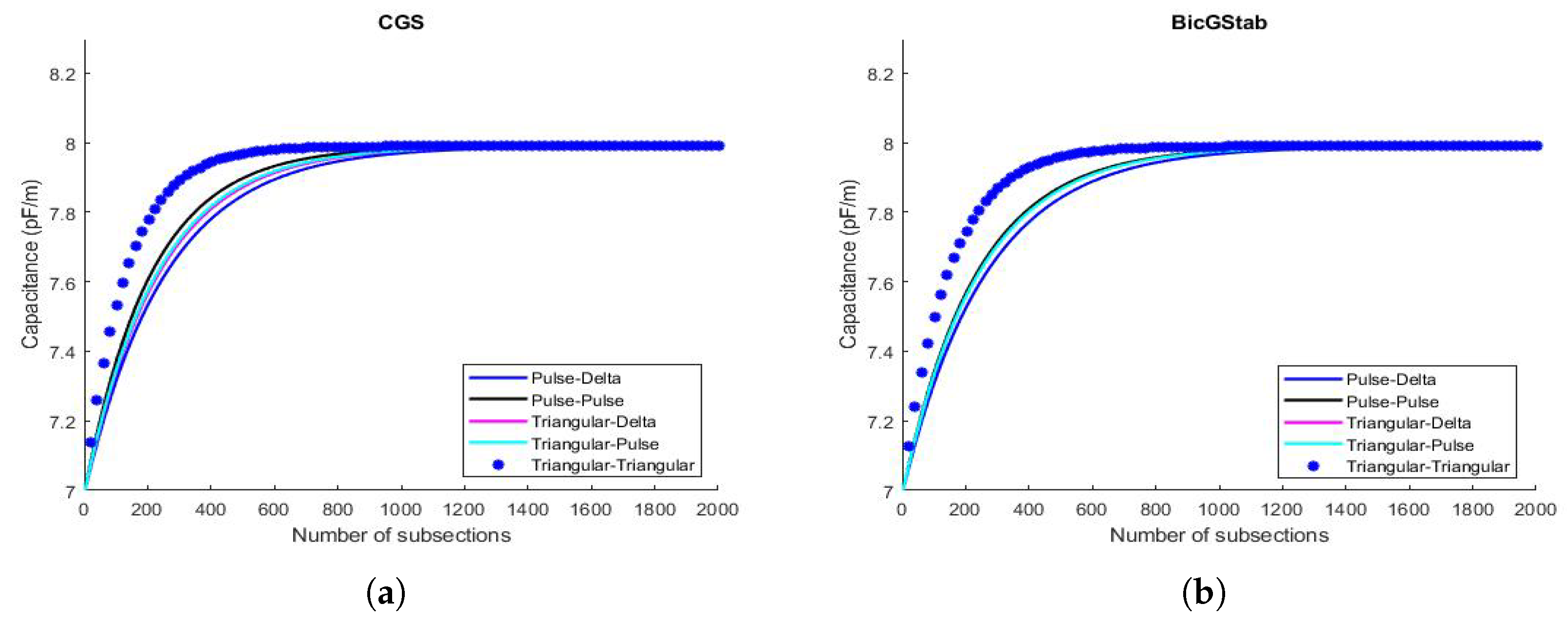
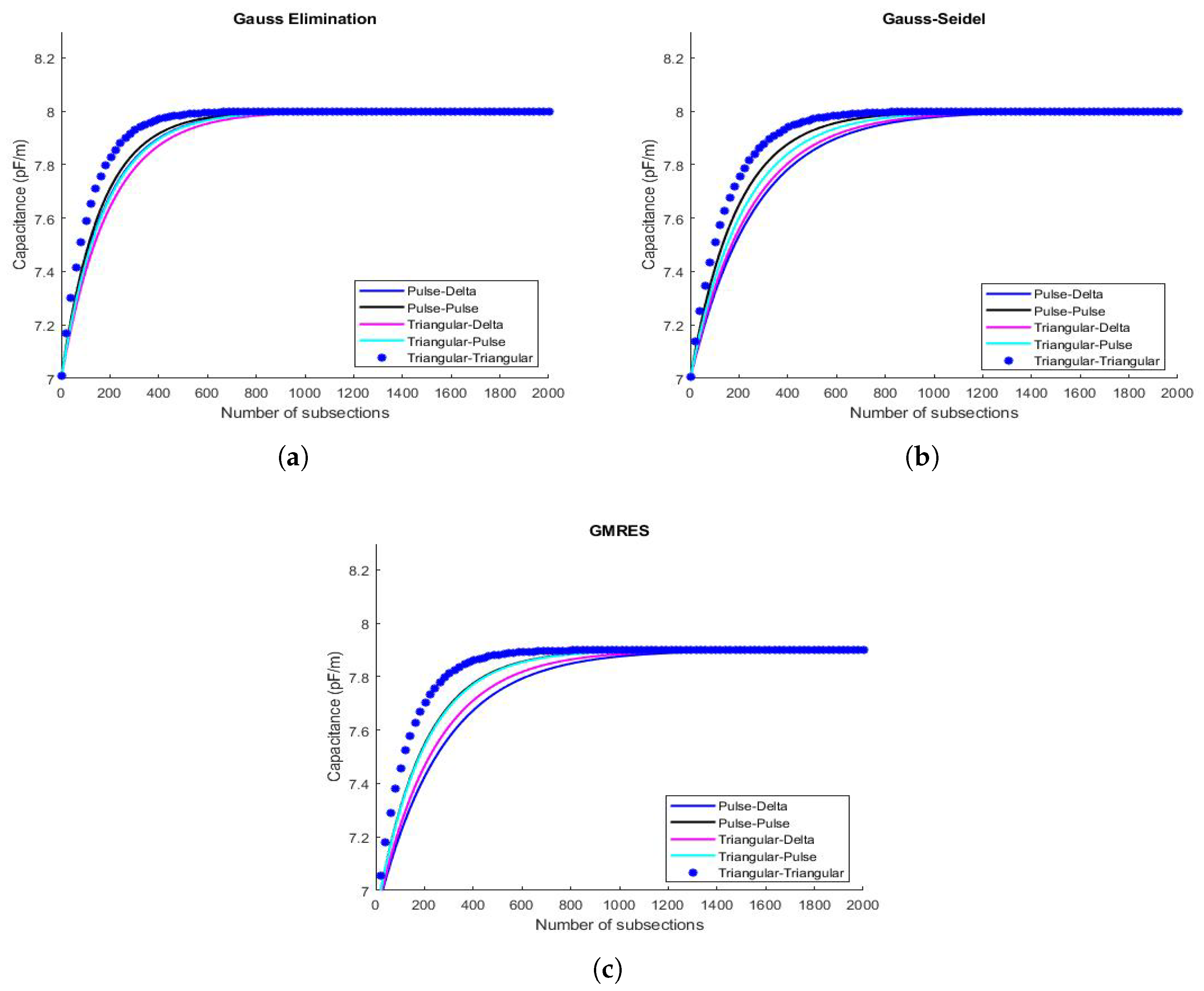
Regarding the convergence of the numerical data related to the electrostatic capacitance C are displayed in Figure 5a,b and Figure 6a–c. In particular, the trends of C versus N, when L ¯ d ratio is equal to 400 for each basis testing functions pairs, are highlighted for each linear system resolution procedure used.
It should be noted that the Gauss elimination method provides values of C very close to each other regardless of the basis-testing functions pair used, while the trend differs considerably with the increase of the subsections while highlighting an obvious saturation behavior as N increases. This is due to the fact that beyond 30 sections, the curve assumes a straight horizontal trend so that the increase in the number of subsections affects the value of C. Similar behavior is exhibited by the performance of the Gauss–Seidel method, even if saturation is obtained with fewer subsections. Furthermore, by increasing the number of subsections, the mesh thickens considerably so that the phenomenon of asymptoticity is felt according to which, whatever the numerical procedure adopted, the values obtained tend to coincide.
Remark 16.
As known, the capacitance of the thin straight wire (finite length) is given by [41]:
C = 2 π ϵ 0 L ¯ Λ 1 + 1 Λ ( 1 ln 2 ) + 1 Λ 2 1 + ( 1 ln 2 ) 2 π 2 12 + o 1 Λ 3
or, numerically,
C = 4 π ϵ 0 2 L ¯ Λ 1 + 0.6137056 Λ + 1.086766 Λ 2 + o 1 Λ 3
where C is the capacitance in ( F ) , ϵ 0 = 1 36 π 10 9 is the permittivity of the free space ( F / m ) and
Λ = ln 2 L ¯ d .
Generally, the values obtained by (98) is an underestimated value of the real value (because there are no infinitesimals of order higher than Λ 2 ); while the values obtained with the procedures based on the Krylov subspaces appear to be slightly overestimated. However, as can be seen from the Figure 3a–c and Figure 4a,b, as the L ¯ / d ratio increases all the values obtained converge. However, even if the convergence is ensured for high values of L ¯ / d (and therefore for large system dimensions) triangular–triangular function pairs converge with the analytical values of capacitance obtained by Equation (98) at a smaller value of L ¯ / d making this pair of functions more attractive than the other pairs. It is worth noting that, even if this pair has a higher computational effort than the other pairs of functions, it provides values that are closer to real values, making this pair of functions more attractive than the other pairs. It is worth noting that, even if this pair has a higher computational cost than the other pairs of functions, it provides values of capacitance that are closer to real values starting from a smaller value of L ¯ / d . Therefore, the higher computational time required for performance with this pair of functions is largely justified by the fact that the obtained capacitance values are more reliable.

6.2. q e & Performance of the Procedures

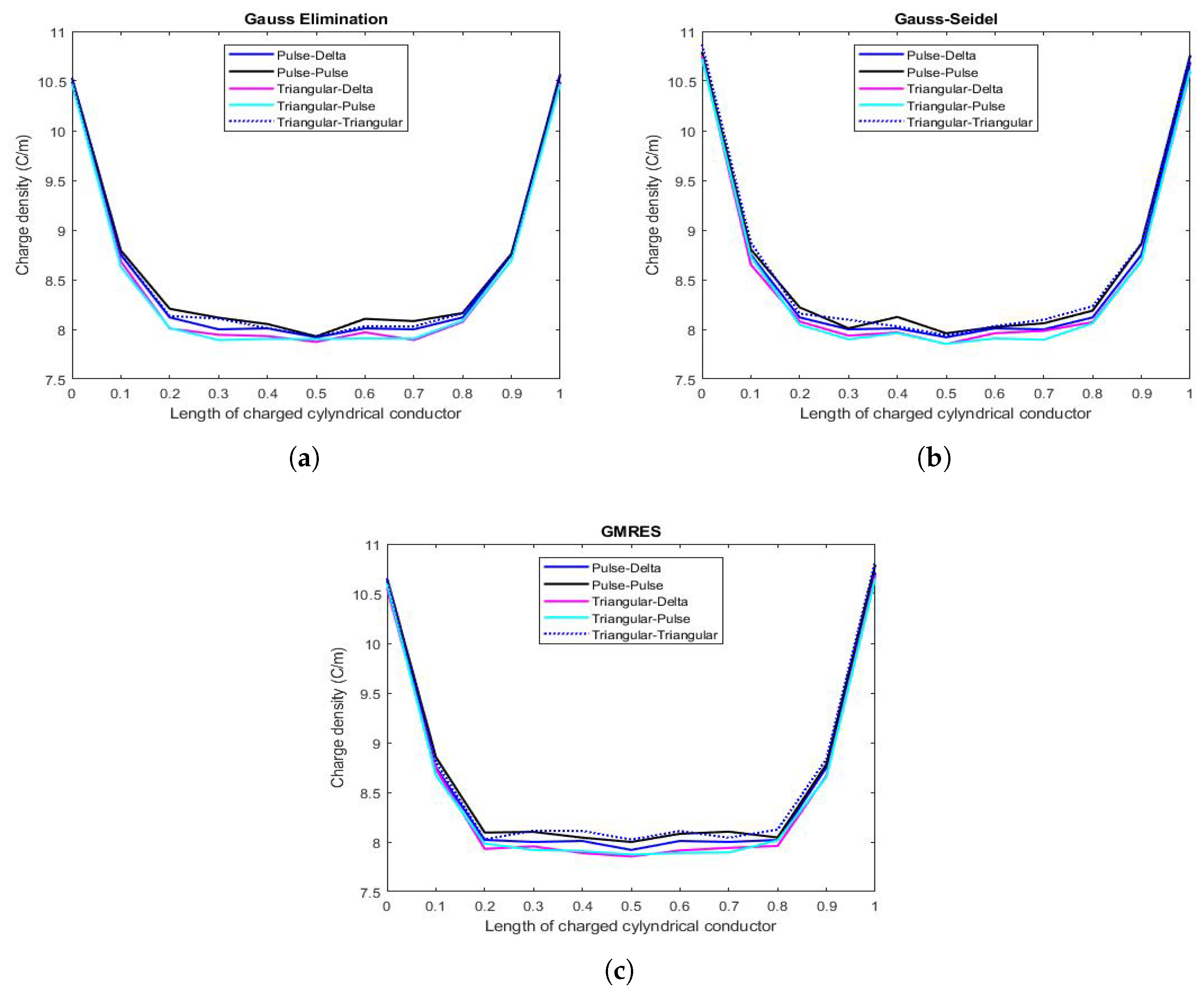
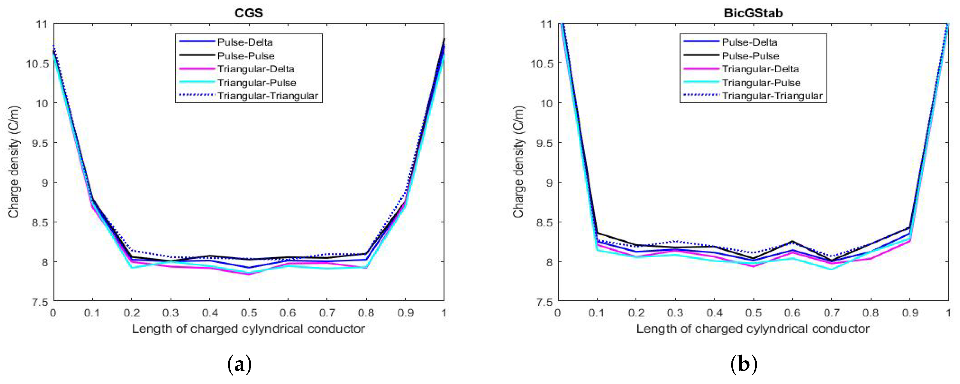
Figure 7a–c and Figure 8a,b show the trend of the electrostatic charge density on the conductor when the L ¯ / d ratio is equal to 400 (when N = 10 ). There are no strong differences regarding the trend of the charge density for unit length when different procedures for solving algebraic system are considered. However, a slight instability is felt in the central area of the conductor, which is most evident when the BicGStab algorithm is used. In contrast, the same methodology provides linear results at the ends of the conductor.
Remark 17.
The procedure based on Krylov subspaces, however, even if they exhibit the same behavior as the Gauss elimination procedure and Gauss–Seidel method with an increase of N (for the phenomenon of asymptoticity), show a more regular behavior before saturation, regardless of the pairs of basis and testing functions used. Furthermore, the distance between the curves for small N are not evident, especially when the BicGStab algorithm is applied, which provides very similar values of C. This is due to the fact that BicGStab, although requiring a higher number of iterations than the other procedures, converges more quickly, as evidenced by the CPU-time obtained. From this analysis, there is no doubt that a key role is played by the number of subsections N that determine the performance of individual procedures as well as trends in the values of C. Hence, the need to formulate appropriate selection criteria for N.

6.3. Selection Criteria for N

Let us introduce the following two definitions.
Definition 4
(norm matrix). As known, a matrix norm is a norm on the vector space K m × n of all matrices of size m × n with entries in a field K. In particular, it is a function [23]
· : K m × n R
such that it satisfies the following properties:
1. 
A 0 , A K m × n ;
2. 
A = 0 if only if A = 0 m × n ;
3. 
α A = | α | A , α K , A K m × n ;
4. 
A + B A + B , A , B K m × n .
Definition 5
(matrix norm induced by vector norms). Let us consider a vector norm ˙ on K m . Then, any A K m × n induces a linear operator from K m to K n with respect to the standard bases. So, the corresponding induced norm on K m × n of A K m × n is defined as follows [23]:
A = sup { A x : x K n , x = 1 } = sup A x x : x K n , x 0 .
For 1 p + , the induced norm is as follows [23]:
A p = sup x 0 A x p x p .
In particular, if p = 2 , it is proved that [23]:
A 2 = λ max ( A * A ) = σ max ( A ) ,
in which σ max ( A ) represents the largest singular value of matrix A (the square root of the largest eigenvalue of the matrix A * A in which A * is the conjugate transpose of A).
Once the matrix norm has been introduced in Definition 4 , two criteria are exploited to choose N. The first criterion acts on the conditioning number of L, K. In particular, for each value of the L ¯ / d ratio and for each pair of basis and testing functions,
K ( N ) = L ( N ) · L 1 ( N ) 1 ,
depending on N, is computed. Thus, setting
max N ( K ( N ) ) L ¯ d = 15 , ( K ( N ) ) L ¯ d = 20 , ( K ( N ) ) L ¯ d = 25 , ( K ( N ) ) L ¯ d = 30 , ( K ( N ) ) L ¯ d = 60 j j { Pulse - Delta , Pulse - Pulse , Triangular - Delta , Triangular - Pulse , Triangular - Triangular }
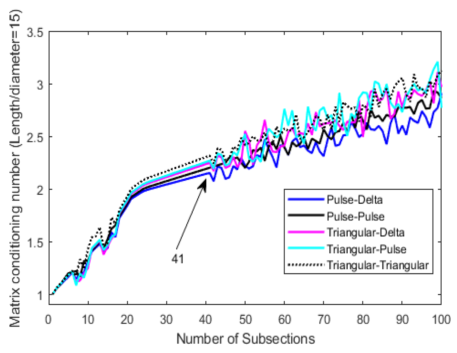
in stability conditions gives us the first choice of N. For example, Figure 9 depicts the trend of K ( N ) depending on N for each basis and testing functions when L ¯ / d = 60 . In this case, the value 41 represents the lower value for N obtained by this criterion when L ¯ / d ratio varies, highlighting that, sometimes, instability arises even if N is a small value. However, strong instability is more evident when N increases.
Remark 18.
We observe that increasing N also increases the number of unknowns and therefore also increases the degree of freedom of the system. This means that λ max in (104) becomes more and more extreme. This leads to a trend of K ( N ) which, starting from 1 when N = 1 , grows with evident instability when N 42 .
The second criterion acts on C. Specifically, for each procedure exploited (Gauss elimination, Gauss–Seidel, GMRES, CGS and BicGStab) and for each L ¯ / d ratio, C is evaluated when N increases. Then,
min max N ( C ( N ) ) L ¯ d = 15 , ( C ( N ) ) L ¯ d = 20 , ( C ( N ) ) L ¯ d = 25 , ( C ( N ) ) L ¯ d = 30 , ( C ( N ) ) L ¯ d = 60 k j k { Gauss Elimination , Gauss - Seidel , GMRES , CGS , BicGStab } j { Pulse - Delta , Pulse - Pulse , Triangular - Delta , Triangular - Pulse , Triangular - Triangular }
in the stability condition, gives us the second choice of N. Finally, the quantity obtained taking the minimum value between (106) and (107) gives us the definitive number of subsection N. In our study, we obtained N 41 .
Remark 19.
We note that the choice of N, understood as a minimum between the values obtained by applying the two criteria described above, is also dictated by the fact that for high values of N, the values of C do not undergo appreciable variations.

6.4. Convergence Speed & CPU-Time

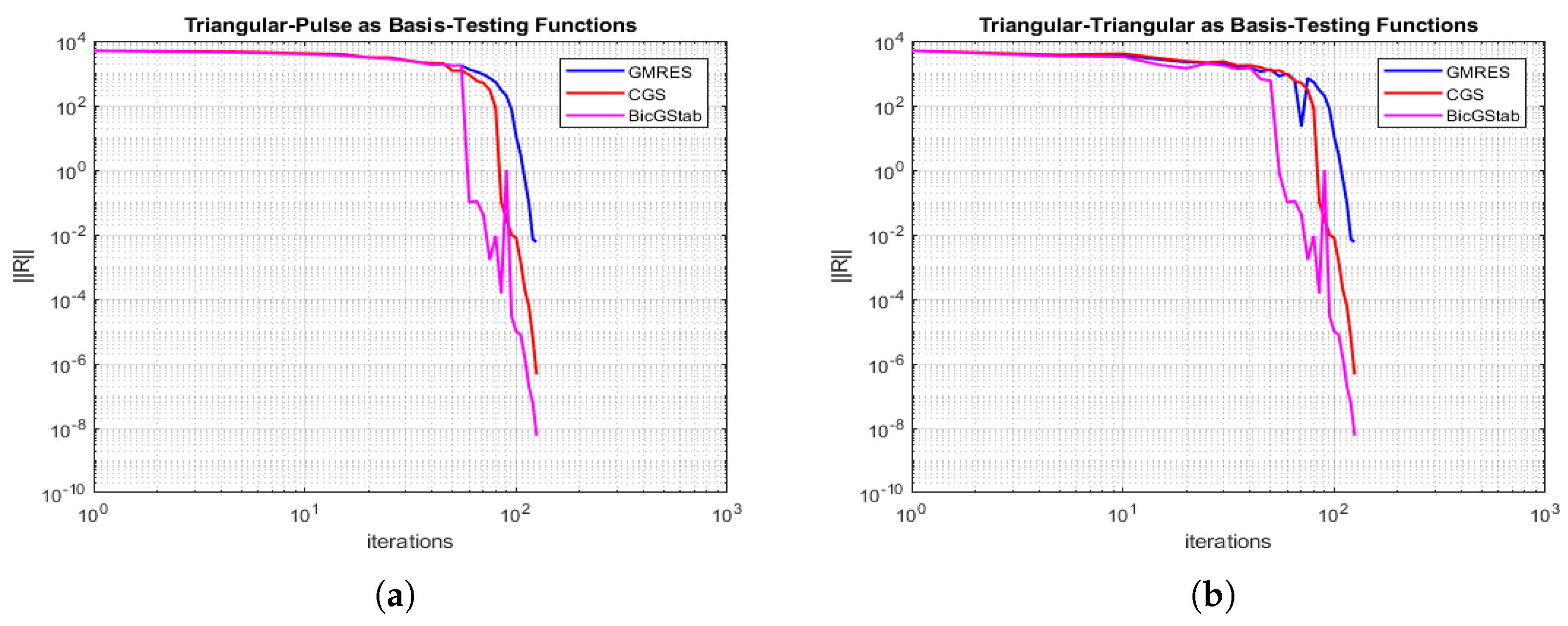
The performance of each procedure was also assessed by the convergence speed computation expressed in terms of R as the number of iterations increased. In particular, for each L ¯ d considered, exploiting an Intel Core 2 CPU 1.45 GHz machine and MatLab ® R2017a, the trends of R were plotted as a function of the number of iterations as both the subspace-based approach of Krylov used (GMRES, CGS, and BicGStab) and for each pair of basis-testing functions. The obtained results, as shown in Figure 10a–c and Figure 11a,b, relating to L ¯ d = 2000 , showed, in logarithmic scale and in all the cases studied, a higher convergence speed of the BicGStab procedure compared to the other approaches.
Remark 20.
It is worth noting that in the case of Triangular–Delta as basis-testing functions and for a low number of iterations, the performances of the three approaches are to be considered equivalent (see Figure 10c). This is due to the fact that in this specific case, the number of subsections is higher providing a better approximation for R without the need, for the GMRES procedure, to resort to restarting.
However, to get complete assessments about the convergence speed of each exploited procedure, the results obtained in terms of R versus the number of iterations must be compared with the CPU-times obtained. Therefore, for each L ¯ d , the CPU-times and number iterations have been computed for GMRES, CGS, and BicGStab and for each pair basis-testing function. In particular, Table 1, Table 2, Table 3, Table 4 and Table 5 display the performance of GMRES in terms of CPU-times as L ¯ d increases, for each pair of basis-testing functions, respectively. Analyzing Table 1, relating to the Pulse–Delta pair, it can be seen that, with the variation of L ¯ d , the restarting procedure allows to obtain more CPU-time content even, if the number of iterations increases. However, for high values of L ¯ d , the CPU-time increases considerably, but in any case, the values obtained are significantly below the values obtained through the methods of Gauss elimination and Gauss–Seidel (see Table 6 and Table 7) in which the calculation times for high values of L ¯ d are extremely dilated so that the performance of the Gauss elimination and Gauss–Seidel methods are not suitable for any real-time applications. The same observations can be extended to the case of the pulse–pulse, triangular–delta, triangular–pulse, and triangular–triangular pairs (see Table 2, Table 3, Table 4 and Table 5) where, even if the CPU-time increases for high values of L ¯ d and becomes more evident, they are still significantly below the values obtained through the Gauss elimination and Gauss–Seidel methods. The performance of the CGS procedure can be considered similar to that of GMRES, as can be seen from the comparison between Table 1, Table 2, Table 3, Table 4 and Table 5 and Table 8 for which the GMRES and CGS procedures, depending on L ¯ d , can be considered equivalent. Both approaches appear slow and expensive in terms of CPU-time since they are applied to linear systems in which the matrices, in addition to being dense, are also non-symmetric. Furthermore, in the GMRES approach, both the Arnoldi iteration and the memorization of all the vectors of the base for the calculation of a new solution worsen the performance. However, the restarting operation partly overcomes this drawback and, even if the number of iterations increases, the CPU-time decreases. It is worth noting that, in these cases, convergence is always guaranteed [23]. Even if the number of iterations increases, BicGStab performs better than the other approaches by providing R below tolerance by an higher number of iterations but with a very lower CPU-time (see Table 9). In particular, as the elements of the matrix increase, the BicGStab procedure is faster than the GMRES procedure. Furthermore, by increasing the number of non-null elements of the matrix, GMRES presents a lower number of iterations but is more time-consuming than the iterations required by the BicGStab procedure which, although being in large numbers, require a lot less time to run. Finally, the performance obtained showed, whatever L ¯ d , an increase in calculation times when the pair triangular–triangular functions as basis-testing functions are considered compared to the other pair basis-testing functions. However, the increase in CPU-times, for these pairs of basis-testing functions, slightly affect performance providing the best performance, taking into account both the CPU-times and the number of iterations to obtain R below the tolerance threshold especially with regard to the BicGStab procedure, which requires half of the iterations to break down R below the tolerance threshold.
Remark 21.
We observe that GMRES minimizes the residual at each iteration. However, as displayed in Figure 10a–c and Figure 11a,b, sometimes the residual increases from one iteration to the next. This is due to the restarting procedure [23].
Finally, the application of the Gauss elimination method and the Gauss–Seidel algorithm did not offer performances comparable with the methods based on Krylov subspaces since the CPU times obtained were much higher, highlighting the non-competitiveness. This is essentially due to the fact that the Gauss elimination method and the Gauss–Seidel algorithm do not take into account the dimension of the matrix of each algebraic system.

7. Conclusions and Perspectives

In this paper, an in-depth comparison among some Krylov subspace method procedures for solving the algebraic linear systems with dense matrix deriving from the application of the MoM for calculating the distribution of the electrostatic charge and the related capacitance of a straight cylindrical conductor of finite length have been presented. Five cases have been identified according to the type of basis-testing functions pair used: (a) pulse function as the basis function and delta function as the testing function (point matching); (b) pulse function as the basis function as well as testing function; (c) triangular function as the basis function and delta function as the testing function (point matching); (d) triangular function as the basis function and pulse function as the testing function; (e) triangular function as the basis function as well as the testing function. For the resolution of the five algebraic linear systems thus obtained, GMRES, CGS, and BicGStab algorithms (all based on Krylov subspaces approaches) have been exploited to achieve the electrostatic charge distribution on the surface of the conductor and capacitance. Numerical results demonstrate the superiority of the BicGStab algorithm in terms of reducing the number of iterations required to reduce the residual norm below the selected tolerance against a reduced increase in CPU-time for each iteration compared to the other considered procedures. In particular, as the size of the matrix increases (due to the increase in the number of subsections of the mesh), the number of iterations required by the BicGStab procedure, compared to the other procedures used, increases significantly but with a significantly reduced CPU-time consumed. In fact, the CPU-time value obtained with BicGStab (25.9 s) is 46.1% lower than the highest CPU-time obtained with the CGS procedure (which is around 48 s) while it is reduced by 27.91% of the highest CPU-time value obtained with the GMRES method (which is around 36 s). Again, it is reduced by 81.93% of the CPU-time value obtained with the Gauss elimination method (around 143 s), and is reduced by 93.1% compared to the higher CPU-time obtained by the Gauss–Seidel iterative procedure. This confirms the indisputable superiority of the BicGStab procedure compared to the others used because, even if it requires a greater number of iterations, it performs them in a considerably more contained time. This research can be considered as an important step especially for a realtime application that requires quick approaches. Finally, the fact that L matrices suffer from the problem of poor conditioning in all cases, in the future, it is desirable to use “ad-hoc” preconditions capable of eliminating (or at least reducing) the effects of this problem.

Author Contributions

Conceptualization, M.V. and G.A.; methodology, G.A.; software, M.V.; validation, M.V. and G.A.; formal analysis, M.V. and G.A.; investigation, M.V.; resources, G.A.; writing—original draft preparation, M.V.; writing—review and editing, G.A. All authors have read and agreed to the published version of the manuscript.

Funding

This research received no external funding.

Conflicts of Interest

The authors declare no conflict of interest.

Abbreviations

The following abbreviations are used in this manuscript:
EMelectromagnetic problems
L differential, integral, or integro-differential operator
hexcitation source
funknown function to be determined
Lalgebraic sparse matrix
MoMmethod of moments
q e electrostatic charge distribution
Celectrostatic capacitance
GMRESgeneralized minimal residual method
CGSconjugate gradient squared
BicGStabbiconjugate gradient Stabilized
O x y z system of Cartesian axes
xlongitudinal symmetry axis of the cylindrical conductor
Ω source region
L ¯ length of the conductor
aradius of the conductor
r vector pointing the observation points
r vector pointing the source points
ϕ ( x ) electrostatic potential
ϵ permittivity of the free space
α n constants to be determined
f n basis functions or expansion functions
Rresidual
Nnumber of sections of the conductor
w m , m = 1 , , N weighting or testing functions
Δ ( x ) Dirac Delta
Velectrical voltage
L m n individual elements of the matrix L
K r Krylov subspace with index r
K k ( A T , b ) Krylov subspace with index k generated by A T and b
Kconditioning number

References

  1. Harrington, R.F. Field Computation by Moment Methods; MacMillan: New York, NY, USA, 1968. [Google Scholar]
  2. Papas, C.H. Theory of Electromagnetic Wave Propagation; Dove Publications, Inc.: New York, NY, USA, 2005. [Google Scholar]
  3. Angiulli, G.; Tringali, S. Stabilizing the E-Field Integral Equation at the Internal Resonances through the Computation of Its Numerical Null Space. Int. J. Appl. Electromagn. Mech. 2010, 32, 63–72. [Google Scholar] [CrossRef] [Green Version]
  4. Dault, D.; Nair, N.V.; Li, J.; Shanker, B. The Generalized Method of Moments for Electromagnetic Boundary Integral Equations. IEEE Trans. Antennas Propag. 2014, 62, 3174–3188. [Google Scholar] [CrossRef]
  5. Jonassen, N. Electrostatics; Springer Nature Switzerland AG: Cham, Switzerland, 2019. [Google Scholar]
  6. Luek, A.; Wolf, V. Generalized Method of Moments for Estimating Parameters of Stochastic Reaction Networks. Syst. Biol. 2016, 10, 98. [Google Scholar]
  7. Gibson, W.C. The Method of Moments in Electromagnetics; Chapman & Hall/CRC; Taylor & Francis Group: Boca Raton, FL, USA; London, UK; New York, NY, USA, 2008. [Google Scholar]
  8. Chakrabarty, S.B. Capacitance of Dielectric Coated Cylinder of Finite Axial Length and Truncated Cone Isolated in Free Space. IEEE Trans. Electromagn. Compat. 2002, 44, 394–398. [Google Scholar] [CrossRef] [Green Version]
  9. Angiulli, G.; Cacciola, M.; Calcagno, S.; De Carlo, D.; Morabito, F.C.; Sgró, A.; Versaci, M. A Numerical Study on the Performances of the flexible BicGStab to Solve the Discretized E-Field Integral Equation. Int. J. Appl. Electromagn. Mech. 2014, 46, 547–553. [Google Scholar] [CrossRef]
  10. Alad, R.H.; Chakrabarty, S.B. Capacitance and Surface Charge Distribution Computations for a Satellite Modeled as a Rectangular Cuboid and Two Plates. J. Electrost. 2013, 71, 1005–1010. [Google Scholar] [CrossRef]
  11. Cacciola, M.; Morabito, F.C.; Polimeni, D.; Versaci, M. Fuzzy Characterization of Flawed Metallic Plates with Eddy Current Tests. Prog. Electromagn. Res. 2007, 72, 241–252. [Google Scholar] [CrossRef] [Green Version]
  12. Burrascano, P.; Callegari, S.; Montisci, A.; Ricci, M.; Versaci, M. Ultrasonic Nondestructive Evaluation Systems: Industrial Application Issues; Springer International Publishing: Cham, Switzerland, 2015. [Google Scholar]
  13. Mishra, M.; Gupta, N.; Dubey, A.; Shekhar, S. A New Algorithm for Method of Moments Solution of Static Charge Distribution. In Proceedings of the 2008 IEEE Regium 10 Colloquium amd the Third International Conference on Industrial and Information Systems, Kharagpur, India, 8–10 December 2008; pp. 1–3. [Google Scholar]
  14. Alad, R.H.; Chakrabarty, S.B. Investigation of Different Basis and Testing Functions in Method of Moments for Electrostatic Problems. Prog. Electromagn. Res. B 2012, 44, 31–52. [Google Scholar] [CrossRef] [Green Version]
  15. Barrett, J.; Formaggio, J.; Corona, T. A Method to Calculate the Spherical Multipole Expansion Electrostatic Charge Distribution on a Triangular Boundary. Prog. Electromagn. Res. B 2015, 63, 123–143. [Google Scholar] [CrossRef] [Green Version]
  16. Hamada, S. Electrostatic Field Analysis of Anisotropic Conductive Media Using Voxe-Based Static Method of Moments with Fast Multipole Method. Eur. J. Comput. Mech. 2016, 25, 54–70. [Google Scholar] [CrossRef]
  17. Maity, K. Capacitance Computation of a Charge Conducting Plate Using Mehod of Moments. Int. J. Res. Sci. Innov. 2018, V, 7–11. [Google Scholar]
  18. Salama, F.; Siwinski, A.; Atieh, K.; Mehrani, P. Investigation of Electrostatic Charge Distribution Within the Reactor Wall Fouling and Bulk Regions of a Gas-Solid Fluidized Bed. J. Electrost. 2013, 71, 21–27. [Google Scholar] [CrossRef]
  19. Ahmed, S.; Sharma, D.; Chaturved, S. Finite-Difference Time-Domain Analysis of Parallel-Plate Capacitors. Int. J. Comput. Methods Eng. Sci. Mech. 2005, 6, 105–114. [Google Scholar] [CrossRef]
  20. Chen, J.; McInnes, L.C.; Xhang, H. Analysis and Practical Use of Flexible BicGStab. J. Sci. Comput. 2016, 68, 803–825. [Google Scholar] [CrossRef]
  21. Van Der Vorst, H. Iterative Krylov Methods for Large Linear Systems; Cambridge University Press: Cambridge, UK, 2003. [Google Scholar]
  22. Simoncini, V.; Szyld, D.B. Recent Computational Developments in Krylov Subspace Methods for Linear Systems. Numer. Linear Algebra Appl. 2007, 14, 112–138. [Google Scholar] [CrossRef] [Green Version]
  23. Trefethen, L.N.; Bau, D. Numerical Linear Algebra; SIAM: Philadelphia, PA, USA, 2018. [Google Scholar]
  24. Parks, M.L.; de Sturler, E.; Mackey, G. Recycling Krylov Subspace for Sequences of Linear Systems. SIAM J. Sci. Comput. 2004, 28, 1–24. [Google Scholar] [CrossRef]
  25. Yang, J.M.; Jiang, Y.L. Krylov Subspace Approximation for Quadratic-Bilinear Differential System. Int. J. Syst. Sci. 2018, 49, 1950–1963. [Google Scholar] [CrossRef]
  26. Tranquilli, P.; Sandu, A. Rosenbrock-Krylov Methods for Large Systems of Differential Equations. SIAM J. Sci. Comput. 2014, 36, A1313–A1338. [Google Scholar] [CrossRef] [Green Version]
  27. Gosselet, P.; Rey, C.; Pebrel, J. Total and Selective Reuse of Krylov Subspaces for the Resolution of Sequences of Non-Linear Structural Problems. Int. J. Numer. Methods Eng. 2013, 94, 60–83. [Google Scholar] [CrossRef] [Green Version]
  28. Wang, S.; de Sturler, E.; Paulino, G.H. Large-Scale Topology Optimization using Precondictioned Krylov Subspace Methods with Recycling. Int. J. Numer. Methods Eng. 2007, 69, 2441–2468. [Google Scholar] [CrossRef]
  29. Harkort, C.; Deutscher, J. Krylov Subspace Methods for Linear Infinite-Dimensional Systems. IEEE Trans. Autom. Control 2011, 56, 441–447. [Google Scholar] [CrossRef]
  30. Beerwerth, R.; Bauke, H. Krylov Subspace Methods for the Dirac Equation. Comput. Phys. Commun. 2015, 188, 189–197. [Google Scholar] [CrossRef] [Green Version]
  31. Saad, Y. Analysis of Some Krylov Subspace Approximations to the Matrix Exponential Operator. SIAM J. Nunerical Anal. 2002, 29, 209–228. [Google Scholar] [CrossRef]
  32. Pedroza-Montero, J.N.; Morales, J.L.; Geudtner, G.; Alvarez-Ibarra, A.; Calaminici, P.; Koester, M. Variational Density Fitting with a Krylov Subspace Method. J. Chem. Theory Comput. 2020, 16, 2965–2974. [Google Scholar] [CrossRef] [PubMed]
  33. Sou-Cheng, T.; Christopher, C.; Saunders, M.A.; Koester, M. MINRES-QLP: A Krylov Subspace Method for Indefinite or Singular Symmetric Systems. SIAM J. Sci. Comput. 2011, 33, 1810–1836. [Google Scholar]
  34. Puzyrev, V.; Cela, J.M. A Review of Block Krylov Subspace Methods for Multisource Electromagnetic Modelling. Geophys. J. Int. 2015, 202, 1241–1252. [Google Scholar] [CrossRef] [Green Version]
  35. Balidemaj, E.; Remis, R.F. A Krylov Subspace Approach to Parametric Inversion of Electromagnetic Data Based on Residual Minimization. PIERS Online 2010, 6, 773–777. [Google Scholar] [CrossRef] [Green Version]
  36. Oscar, B.; Elling, T.; Paffenroth, R.; Catalin, T. Electromagnetic Integral Equations Requiring Small Number of Krylov-Subspace Iterations. J. Comput. Phys. 2009, 228, 6169–6183. [Google Scholar]
  37. Huang, B.; Xie, Y.; Ma, C. Krylov Subspace Methods to Solve a Class of Tensor Equations via the Einstein Product. Numer. Linear Algebra Appl. 2019, 26, 122–139. [Google Scholar] [CrossRef]
  38. Jaimoukha, I.M.; Kasenally, E.M. Krylov Subspace Methods for Solving Large Lyapunov Equations. SIAM J. Numer. Anal. 2004, 31, 227–251. [Google Scholar] [CrossRef] [Green Version]
  39. Freund, R.W. Krylov Subspace Methods for Reduced-Order Modeling in Circuit Simulation. J. Comput. Appl. Math. 2000, 123, 395–421. [Google Scholar] [CrossRef] [Green Version]
  40. Heres, P.; Schilders, W. Krylov Subspace Methods in the Electronic Industry. In Progress in Industrial Mathematics at ECMI 2004; Springer: Berlin/Heidelberg, Germany, 2006; Volume 8, pp. 227–239. [Google Scholar]
  41. Jackson, J.D. Charge Density on Thin Straight Wire, Revisited. Am. J. Phys. 2000, 68, 789–799. [Google Scholar] [CrossRef]
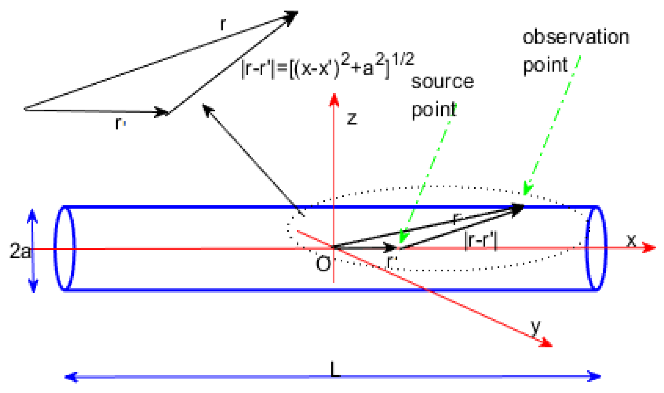
Figure 1. Cylinder with length L ¯ and radius a. r and r are the position on which the potential ϕ (observation point) is evaluated and the position of the charge distribution on the cylinder, respectively (source point).
Mathematics 08 01431 g001
Figure 2. (a) Pulse functions and (b) triangular functions.
Mathematics 08 01431 g002
Figure 3. C vs. L ¯ / d ratio for each basis-testing functions with the (a) Gauss elimination procedure, (b) Gauss–Seidel method and (c) GMRS algorithm.
Mathematics 08 01431 g003
Figure 4. C vs. L ¯ / d ratio for each basis-testing functions with the (a) CGS algorithm and (b) BicGStab procedure.
Mathematics 08 01431 g004
Figure 5. C vs. N when L ¯ / d ratio is equal to 400 for each basis and testing functions: (a) CGS and (b) BicGStab algorithms.
Mathematics 08 01431 g005
Figure 6. C vs. N when L ¯ / d ratio is equal to 400 for each basis and testing functions: (a) Gauss elimination; (b) Gauss–Seidel procedures; (c) GMRES algorithm.
Mathematics 08 01431 g006
Figure 7. Charge density vs. L ¯ for L ¯ d = 400 when (a) Gauss elimination procedure; (b) Gauss–Seidel methods and (c) GMRES algorithm are exploited.
Mathematics 08 01431 g007
Figure 8. Charge density vs. L ¯ for L ¯ d = 400 when (a) CGS and (b) BicGStab algorithms are exploited.
Mathematics 08 01431 g008
Figure 9. K ( L ) vs. N with different B/T functions.
Mathematics 08 01431 g009
Figure 10. R vs. number of iterations for GMRES. CGS and BicGStab algorithms: (a) pulse–delta (b) pulse–pulse (c) triangular–delta functions as basis-testing functions.
Mathematics 08 01431 g010
Figure 11. R vs. number of iterations for GMRES. CGS and BicGStab algorithms: (a) triangular–pulse (b) triangular–triangular functions as basis-testing functions.
Mathematics 08 01431 g011
Table 1. GMRES: CPU-time (s) and #iterations for pulse–delta basis-testing functions as L ¯ d changes.
GMRES
L ¯ / d IterationsPulse–Delta
CPU-Time
Restarting IterationsCPU-Time
622.014032.0090
1022.140032.0190
1522.281332.2217
2022.250132.2307
2532.187552.1755
3032.328152.1875
6032.671952.5313
10052.546972.3906
25062.796982.6875
50064.093883.9063
1000711.0000810.2656
2000848.6719932.2188
Table 2. GMRES: CPU-time (s) and #iterations for each pair pulse–pulse basis-testing functions as L ¯ d changes.
GMRES
L ¯ / d IterationsPulse–Pulse
CPU-Time
Restarting IterationsCPU-Time
622.796932.6063
1022.843832.6094
1523.015633.0125
2022.687532.6399
2532.390632.2501
3032.091032.0154
6032.671942.5750
10042.699942.8910
25043.140643.0694
50044.187553.9219
100059.343867.2344
2000634.3281732.7344
Table 3. GMRES: CPU-time (s) and #iterations for triangular–delta basis-testing functions as L ¯ d changes.
GMRES
L ¯ / d IterationsTriangular–Delta
CPU-Time
Restarting IterationsCPU-Time
622.734432.5781
1022.765633.0156
1522.562532.4844
2032.718832.2500
2532.796942.3281
3032.781342.2344
6032.640642.1875
10032.671942.6250
25043.462543.3906
50044.328153.4375
100058.625068.5938
2000642.7813737.3750
Table 4. GMRES: CPU-time (s) and #iterations for triangular–pulse basis-testing functions as L ¯ d changes.
GMRES
L ¯ / d IterationsTriangular-Pulse
CPU-Time
Restarting IterationsCPU-Time
622.828133.0625
1023.125032.9844
1522.531332.2344
2032.593832.2031
2532.238442.1875
3033.000042.1563
6032.437542.3594
10043.234452.9688
25042.734452.7188
50053.515663.4250
100069.796979.1250
2000634.2500731.0587
Table 5. GMRES: CPU-time (s) and #iterations for triangular–triangular basis-testing functions as L ¯ d changes.
GMRES
L ¯ / d IterationsTriangular–Triangular
CPU-Time
Restarting IterationsCPU-Time
622.058932.0358
1022.082531.9875
1522.187532.0987
2032.515632.1719
2532.625042.2656
3032.140642.3594
6032.406342.4001
10042.7656524844
25042.421952.4089
50054.312563.8281
100068.515677.7188
2000635.9219733.4688
Table 6. Gauss elimination: CPU-time (s) for each pair basis-testing functions as L ¯ d changes.
Gauss Elimination
Pulse–DeltaPulse–PulseTriangular–DeltaTriangular–PulseTriangular–Triangular
L ¯ / d CPU-TimeCPU-TimeCPU-TimeCPU-TimeCPU-Time
60.03130.01560.01560.01560.0156
100.01560.01630.01690.01730.0174
150.04340.04360.04330.04690.0521
200.06250.06910.07290.07850.0873
250.07940.07490.07570.07890.0798
300.08130.08360.08490.08750.0899
600.23130.21560.25150.27900.2873
1000.32900.33340.3512035860.3599
2500.62500.60940.64060.65630.7344
5002.07812.06252.43752.31252.4219
100015.718817.062517.906317.656318.2031
2000115.6875117.3281117.8125122.5781143.3438
Table 7. Gauss–Seidel: CPU-time (s) and number of iterations for each pair basis-testing functions as L ¯ d changes.
Gauss–Seidel
Pulse–DeltaPulse–PulseTriangular–DeltaTriangular–PulseTriangular–Triangular
L ¯ / d CPU-TimeCPU-TimeCPU-TimeCPU-TimeCPU-Time
60.00780.00930.00990.00890.0080
100.01450.01300.00960.01170.0159
150.01920.01950.01480.01710.0216
200.02450.02790.03140.03010.0317
250.03050.03770.02880.03130.0399
300.04430.04370.05340.08290.0827
600.14760.23090.22840.23780.1849
1000.40460.58060.46400.56680.5505
2503.09924.46174.92775.41856.4172
50016.049718.541121.945220.621920.8443
100063.552374.659871.021380.408372.5813
2000326.7238311.5719321.5325352.0632377.7439
Table 8. CGS: CPU-time (s) and number of iterations for each pair basis-testing functions as L ¯ d changes.
CGS
Pulse-Delta Pulse-Pulse Triangular-Delta
L ¯ / d IterationsCPU-TimeIterationsCPU-TimeIterationsCPU-Time
622.015122.784122.6999
1022.123522.889122.7391
1522.278923.004522.5701
2022.212422.658722.7089
2532.182232.392432.7899
3032.321432.089232.7796
6032.674532.675232.6498
10052.540252.690552.6746
25062.791263.138263.4601
50064.159864.192664.3301
1000711.054879.387578.6254
2000848.0254834.0369842.9816
CGS
Triangular-Pulse Triangular-Triangular
L ¯ / d IterationsCPU-TimeIterationsCPU-Time
622.810122.5147
1023.134122.0799
1522.540122.1798
2022.589922.5124
2532.232232.6212
3032.997132.1427
6032.430132.3983
10053.231452.7691
25062.739162.4290
50063.514964.3259
100079.978278.5203
2000834.9311835.9315
Table 9. BicGStab: CPU-time (s) and number of iterations for each pair basis-testing functions as L ¯ d changes.
BicGStab
Pulse-Delta Pulse-Pulse Triangular-Delta
L ¯ / d IterationsCPU-TimeIterationsCPU-TimeIterationsCPU-Time
650.218850.343850.4531
10120.2656110.5156140.3125
15280.2969200.4844210.2656
20480.1563480.1496380.1094
25590.2500640.2500930.2188
301340.1250500.14061810.4219
601300.5008680.60942860.3125
1001890.34383070.39062040.3281
250980.53138510.7969950.4219
5003170.89062510.51563250.6875
10003041.31253201.39061430.8906
200046824.828179925.843992424.4219
Triangular-Pulse Triangular-Triangular
L ¯ / d IterationsCPU-TimeIterationsCPU-Time
650.398750.4193
10160.2188160.2982
15260.2656270.0938
20670.2656630.2188
25650.2969900.1875
301970.26561410.1406
601350.37503440.3281
1001910.40631790.5625
2504490.79691150.3750
5004160.76562350.5625
10003951.59381130.5781
2000101325.5000102325.9243