Article

Coordination in Coupled Arrays of Stiff Filaments—Modelling and Simulation

Department of Mechanical Engineering, University of Ottawa, Ottawa, ON K1N 6N5, Canada
Mathematics 2020, 8(8), 1282; https://doi.org/10.3390/math8081282
Submission received: 31 May 2020 / Revised: 3 July 2020 / Accepted: 21 July 2020 / Published: 3 August 2020
(This article belongs to the Special Issue Applied Mathematical Methods in Mechanical Engineering)

Abstract

:
We present the mechanical model of an array of elastic filaments and simulate the response with different mechanical couplings. This class of systems is inspired by robust and elegant solutions for locomotion mechanics that have emerged in several small-scale biological entities in the form of beating protrusions, such as cellular cilia and eukaryotic flagella. The collective dynamics of cilia arrays reveals important features such as array alignments, two-phase asymmetric beating of individual filaments, and the emergence of metachronal coordination, which make them suitable for bio-inspired terrestrial and aquatic locomotion. The model presented here is the basis for further developments towards the design of terrestrial and aquatic locomotion systems for general purpose robotic devices.

1. Introduction

Several small-scale biological entities have evolved highly adaptable, low specialization locomotion mechanics systems in the form of beating protrusions, such as cellular cilia and eukaryotic flagella [1,2]. The fundamental structure of many eukaryotic cilia and flagella is the axoneme, which is a regular cylindrical arrangement of elastic filaments connected by motor proteins, which act as active elements from the perspective of actuation and induce beating patterns at the core of locomotion actions for small-scale motility [3,4].
The biomechanics of axonemal beating protrusions is extensively studied in the context of solid-fluid interaction, with the investigation often focused on the emergence of beating patterns induced by the coupling with an external flow [2,3,5,6,7]. Fluid interactions and induced beating evolution in small-scale protrusions are of particular interest in mathematical biology, since they are at the core of micro-swimming and also relate to important physiological and developmental phenomena such as mucous flow control and protection against infections, as well as embryonic development [8,9]. From the perspective of locomotion in fluids, the collective dynamics of cilia arrays has important implications as it reveals important aspects such as array alignments, two-phase asymmetric beating of individual filaments, and the emergence of metachronal coordination [10,11,12]. Metachronal coordination in arrays of coupled protrusions consists of synchronization with constant phase shift between contiguous elements, resulting in travelling waves through the array, ultimately associated with locomotion mechanics.
Recent work in [13] proposed that emerging metachronal waves in arrays of stiff filaments are also fundamentally related to mechanical coupling through the base in addition to hydrodynamic coupling, suggesting that the emergence of metachronal waves can be achieved by pure basal mechanical coupling. This has important implications for terrestrial locomotion, since from a design point of view, arrays of flexible protrusions are a robust solution as they can adapt and morph to a variety of terrains, and from the dynamics point of view, metachronal coordination and travelling waves are suitable to induce motion when the protrusions engage with a substrate/terrain. Once the dynamics of this class of systems can be predicted, important optimization considerations for robotics applications can be addressed, such as minimal actuation constraints and induced coupling topologies to minimize energy consumption and maximize autonomy, for example.
Here, we present the mechanical model of an array of elastic filaments connected through an elastic medium (base) and consider different basal elastic couplings, namely forces and couples. Each filament is considered as a stiff polymer with an active internal force, consistent with axonemal structures. This class of mechanical objects is suitably modelled by using constrained Euler elastica, resulting in coupled nonlinear PDEs describing the evolution of a kinematic descriptor for the geometric shape, and a Lagrange multiplier that enforces inextensibility. The response is simulated for different coupling schemes, hinting at possible designs for walker-type locomotion mechanics based on their collective dynamics. Further developments are focused on general purpose robotic devices, which are attractive solutions for a variety of applications that include environmental monitoring and protection, civilian and military defence, and generally hazardous missions [14,15,16,17,18].

2. Stiff Filaments with Internal Action

A cross-sectional image and a schematic of an axonemal structure are shown in Figure 1, reproduced from [19] with the author’s permission. Axonemes are the fundamental structures at the core of locomotion of small-scale structures like cells and bacteria, in which it is often achieved through the beating of cilia and flagella protrusions. Axonemal beating is the complex result of the co-action of internal electrochemical motors and of external forces resulting from hydrodynamic interactions and from forces transmitted through the base [3]. The resulting nonlinear mechanics allows for the emergency of a variety of possible patterns, which confer robustness and adaptability to this type of structure with respect to the locomotion function and suggest the possibility that the solution obtained at the evolutionary scale could be fundamental and therefore desirable in engineered systems designed to engage unknown environments.
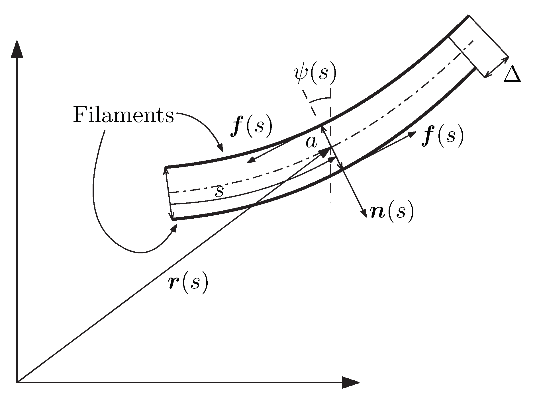
A simplified mechanical model for an axonemal beating structure in two dimensions is schematised in Figure 2, in which two filaments are separated by approximately a constant distance 2 a [19]. The arc length s spans the neutral axis of the system with position vector r ( s ) , and points on the boundary filaments are described by the position vectors r 1 ( s ) = r ( s ) + a n ( s ) and r 2 ( s ) = r ( s ) a n ( s ) , where n is the unit normal to the neutral axis. The bending of the system is driven by an internal system of shear forces f ( s ) [4]. In biological active filaments, the internal forces f ( s ) result from the concurrent effect of dynein motors (active) and passive elastic connection across microtubule doublets. The bending stiffness of the filaments is related to an internal bending moment that works on the curvature. In an engineered realization of the same systems, passive and active links can be reproduced respectively by distributed motors and by viscoelastic links.
At every point, the pair of equal magnitude and opposite sign forces f is equivalent to an internal couple (bending moment) of magnitude a f . The internal forces induce relative sliding of the filaments, which is related to the slope of the neutral axis by [19]:
Δ ( s ) = Δ ( 0 ) + a ψ ( s ) ψ ( 0 )
Therefore:
Δ ( s ) = a ψ ( s ) = a κ ( s )
where κ is the curvature of the neutral axis. The equations of motions can be derived from an action principle [20]. Let r ( s , t ) be generalized coordinates describing the neutral axis of the system. We have:
r ( s , t ) = r ( 0 , t ) + 0 s cos ψ ( σ , t ) , sin ψ ( σ , t ) d σ
where ψ ( s , t ) is the local tangent angle to the neutral axis, with respect to a global coordinate frame. If L and R are respectively the Lagrangian and the Rayleigh dissipation function of the system, then the equations of motion are:
d d t L r ˙ L r = R r ˙
The Rayleigh dissipation function is quadratic in the generalized velocities:
R = c 2 0 r ˙ · r ˙ d s
with c being a constant dissipation constitutive parameter. We model this system as a nonlinear rod, governed by curvature with a distributed system of internal shearing forces f ( s , t ) . The potential energy of the system is given by [20]:
E = 0 k M 2 κ 2 + f Δ + λ 2 r · r d s
where λ is a multiplier that enforces the local inextensibility condition r · r = 0 . For small deformations, the curvature is the second derivative of the transverse displacement, and the potential energy reduces to the one of an inextensible Euler beam. Since s is an arc length, the following intrinsic relations define the tangent and the normal vectors to the parametric curve r :
t = r
t = κ n , n = κ t
The kinetic energy of the system is given by:
K = 1 2 0 ϱ r ˙ · r ˙ d s
where the superimposed dot means the time derivative.
The variation of the potential energy gives:
δ E = 0 k M κ a F δ κ + λ r · δ r d s
where f = f is the magnitude of f , and:
F ( s ) = s f ( σ ) d σ
By using the relation δ κ = δ ( n · r ) = n · δ r [1] Appendix A and by two integrations by parts, we obtain:
δ E = 0 ( k M κ a F ) n ( k M κ 2 a F κ + λ ) t · δ r d s + ( k M κ a F ) n · δ r 0 + ( k M κ 2 a F κ + λ ) t ( k M κ a F ) n · δ r 0
Boundary terms conjugate to δ r are boundary bending moments, and boundary terms conjugate to δ r are external forces, with explicit tangential and normal components. By introducing:
τ = k M κ 2 a F κ + λ
we can see that this quantity is the integrated tangential component of the forces acting on the filament, and therefore, it acts as a physical tension. This gives also an interpretation to λ , which is the portion of the physical tension necessary to enforce the inextensibility condition.
The equations of motion for a single filament are:
ρ r ¨ + ζ r ˙ + ( k M κ a F ) n ( k M κ 2 a F κ + λ ) t = 0
with boundary conditions:
s = : F = ( k M κ a f ) n + τ t or r ( , t ) = 0 M = k M κ or ψ ( , t ) = 0
s = 0 : F 0 = ( k M κ a f ) n τ t or r ( 0 , t ) = 0 M 0 = k M κ + a F ( 0 , t ) or ψ ( 0 , t ) = 0
where F 0 , F , M 0 , M are external forces and moments applied at the boundaries. In order to obtain evolution equations for ψ and τ , we first consider the following:
r ˙ = t ˙ = ψ ˙ n
r ¨ = ψ ¨ n ψ ˙ 2 t
Therefore:
( ρ ψ ¨ + ζ ψ ˙ ) n ρ ψ ˙ 2 t ν n + τ t = 0
where ν = ( k M κ a f ) . By carrying out the spatial derivatives:
( ν n + τ t ) = ( ν ν κ 2 + 2 τ κ + τ κ ) n + ( τ τ κ 2 2 κ ν ν κ ) t
Therefore, by projecting along n and t , we obtain the governing equations:
ρ ψ ¨ + ζ ψ ˙ + k M ψ I V a f ( k M ψ a f ) ψ 2 2 τ ψ τ ψ = 0
ρ ψ ˙ 2 τ + τ ψ 2 2 ψ ( k M ψ a f ) ψ ( k M ψ a f ) = 0
In order to close the system, we need a constitutive model for f, which is in general comprised of a passive and an active component. Different constitutive models have been considered in the literature [1,4] to fit observations about flagella beating, specifically focusing on passive elastic coupling and on the active action related to dynein motors. Here, we do not specify the active component in order to isolate the effect of the basal coupling, and we consider the passive component to be described by the linear relation:
f = k f Δ = k f a ψ
with the elastic constant k f characterized as:
k f = E f A f a 2
where E f and A f are respectively Young’s modulus of the filaments’ material and cross-sectional area.
At the boundary s = 0 , we consider an elastic coupling with the body of the robotic device, which will be discussed in the following subsection. For the purpose of this study, we are interested in the dynamics induced by the basal coupling, and therefore, we consider the extremes at s = to be free. The boundary conditions will be formalized below.

3. Weak Form and Finite Element Formulation

The dynamics of the system of coupled stiff filaments is simulated by using finite elements implemented in a code written in Mathematica© 12. The finite element solution is based on the following weak or variational form of the system of governing equations.
For i = 1 , , N , define the arc-length s i [ 0 , ] spanning the neutral axis of the ith filament. For s i ( 0 , ) , that is in the open interval spanning the neutral axis, the plane dynamics of the ith filament is governed by the following set of equations adapted from (20):
ρ ψ ¨ i + ζ ψ ˙ i + k M ψ i I V a f i ( k M ψ i a f i ) ψ i 2 2 τ i ψ i τ i ψ i = 0
ρ ψ ˙ i 2 + τ i τ i ψ i 2 + 2 ψ i ( k M ψ i a f i ) + ψ i ( k M ψ i a f i ) = 0
Therefore, there are in total 2 N fields ( ψ i , τ i ) to which we associate the 2 N test function fields ( ψ ˜ i , τ ˜ i ) , which can be interpreted as the variations of the states in the sense of the calculus of variations, or otherwise, they can be interpreted as test functions in the framework of numerical approximation methods. The test functions satisfy homogeneous boundary conditions assigned to the trial solutions ψ i and τ i [21]. Integration with respect to s i over the domain [ 0 , ] after multiplying the expressions in (23) respectively by ψ ˜ i and τ ˜ i gives:
0 ρ ψ ¨ i + ζ ψ ˙ i + k M ψ i I V a f i ( k M ψ i a f i ) ψ i 2 2 τ i ψ i τ i ψ i ψ ˜ i d s i + 0 ρ ψ ˙ i 2 + τ i τ i ψ i 2 + 2 ψ i ( k M ψ i a f i ) + ψ i ( k M ψ i a f i ) τ ˜ i d s i = 0
Integration by parts of different terms (see Appendix A) gives:
0 ρ ψ ¨ i + ζ ψ ˙ i ψ ˜ i + k M ψ i a f i ψ ˜ i ψ i 2 ψ i ˜ τ i ψ i ψ ˜ i + τ i ψ i ψ ˜ i d s i + 0 ρ ψ ˙ i 2 τ i ψ i 2 τ ˜ i ( k M ψ i a f i ) ψ i τ ˜ i + 2 ψ i τ ˜ i τ i τ ˜ i d s i + k M ψ i a f i + τ i ψ i ψ ˜ i 0 k M ψ i a f i ψ ˜ i 0 + 2 ψ i ( k M ψ i a f i ) + τ i τ ˜ i 0
From the boundary terms, we establish the following variational duality relations:
k M ψ i a f i + τ i ψ i ψ ˜ i
k M ψ i a f i ψ ˜ i
2 ψ i ( k M ψ i a f i ) + τ i τ ˜ i
Since ψ i = κ i is the curvature, by using the physical quantities introduced in Section 2, the duality relations can be rewritten as:
ν i + κ i τ i ψ ˜ i
ν i κ ˜ i
τ i 2 κ i ν i τ ˜ i
which shows that the dual of the tension τ is the tension per unit length τ 2 κ ν , where M = k M κ a F is the moment, which is also minus the integral of the normal force ν = ( k M κ a f ) .

3.1. Boundary Conditions and Coupling

At the free end of each filament, all the dynamic quantities are zero, and therefore, the boundary terms in (25) evaluated at s i = are set to zero. On the other hand, the coupling between filaments through the base is expressed through the boundary terms evaluated at s i = 0 .
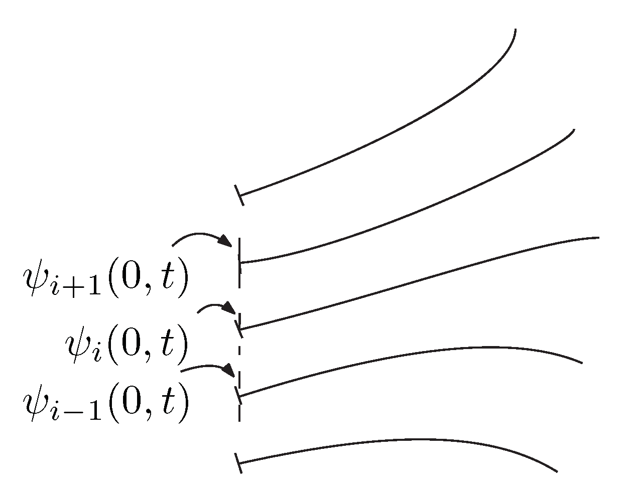
The idea of basal coupling is schematised in Figure 3, which shows an array of stiff filaments anchored to a base that provides the coupling. The array includes N filaments labelled with the integer i = 1 , 2 , , N , each described by a curvilinear abscissa s i [ 0 , ] , where is the common length. In Figure 3, the field ψ i ( 0 , t ) is the rotation of the ith filament at the point of attachment to the base.
To model rigid coupling, one would impose kinematic constraints of the type j = 1 N a j ψ j ( 0 , t ) = 0 or j = 1 N b j κ j ( 0 , t ) = 0 for some set of coefficients a j or b j . On the other hand, force coupling through the base is appropriately modelled through boundary forces and moments that are exerted on each filament as specified by the boundary terms at s i = 0 in (25). The appropriate force terms are identified by the duality relations (27). Based on these relations, we define the generalized normal force, the generalized moment, and generalized tangential force respectively as the duals of the rotation ψ , the curvature κ , and the tension τ :
μ i : = ν i + τ i κ i
ν i : = M i
θ i : = τ i 2 κ i ν i
Note that the just introduced generalized forces and moments involve derivatives of the original physical quantities introduced in Section 2 since the model (23) is obtained from (14) by taking a spatial derivative of the position vector r to express the system in terms of ψ and τ .
There are multiple possibilities to express the coupling among filaments through the generalized dynamic quantities just defined. Here, we consider the relatively simple possibility of modelling it as constitutive relations between generalized boundary forces and moments and boundary kinematic quantities. For rotation coupling, the boundary terms (in (25)) duals of ψ ˜ i are then given by:
μ i ( 0 , t ) = α μ j = 1 N σ i j ( t ) ψ j ( 0 , t ) ψ i ( 0 , t ) + μ ¯ i ( t )
where μ ¯ i ( t ) is an actuation for the ith filament, α μ is a constitutive parameter that plays the role of coupling strength, and σ i j ( t ) [ 0 , 1 ] is the coupling between filament j and filament i. From the perspective of robotic applications, the actuation terms μ ¯ i act as inputs, and for the purpose of energy consumption, one would want to minimize the number of such terms, ideally having only one actuation with action propagated through the base to the non-actuated filaments. Moreover, more sophisticated analysis could involve the optimization through the coupling network topology induced by the distribution of coefficients σ i j ( t ) , which play the role of weighted network links between nodes constituted by the extremes of the filaments attached to the base. The coupling in (31) can accommodate finite difference operators and therefore common lattice network structures. For example, for:
σ i j = 1 , j = i + 1 1 , j = i 1 0 , otherwise
the coupling has the structure of a second order central difference ψ i + 1 ( 0 , t ) 2 ψ i ( 0 , t ) + ψ i 1 ( 0 , t ) , which, upon introduction of the normalized coupling strength k ¯ M = h 2 k M , where h is the distance between two filament attachment points on the base, allows studying a system with many filaments described by the limit:
lim h 0 ψ i + 1 ( 0 , t ) 2 ψ i ( 0 , t ) + ψ i 1 ( 0 , t ) h 2 = lim h 0 Ψ ( S + h , t ) 2 Ψ i ( S , t ) + Ψ ( S h , t ) h 2 = Ψ ( S , t )
where Ψ is the field describing the rotation of the distribution of filaments at the interface with the base and S is a curvilinear abscissa.
Similarly, for curvature coupling, the boundary terms duals of κ ˜ i in (25) are given by:
ν i ( 0 , t ) = α ν j = 1 N σ i j ( t ) κ j ( 0 , t ) κ i ( 0 , t ) + ν ¯ i ( t )
where ν ¯ i is an actuating generalized moment. If the rotation at the basis is prescribed, then ψ ˜ i ( 0 ) = 0 , and similarly for the curvature.

3.2. Finite Element Discretization

To obtain numerical solutions for (25) with coupling boundary conditions, the set of trial solutions ψ i and τ i and the related test functions ψ ˜ i and τ ˜ i are projected onto finite element basis functions. Each domain [ 0 , ] is discretized by n nodes with coordinates s i j [ 0 , ] , for j = 1 , , n . Trial solutions and test functions are approximated by the expansions:
ψ i ( s i , t ) = k = 1 n ϕ ψ k ( s i ) a i k ( t ) + ϕ κ k ( s i ) b i k ( t )
τ i ( s i , t ) = k = 1 n ϕ τ j ( s i ) c i k ( t )
ψ ˜ i ( s i , t ) = k = 1 n ϕ ψ k ( s i ) a ˜ i k + ϕ κ j ( s i ) b ˜ i k
τ ˜ i ( s i , t ) = k = 1 n ϕ τ k ( s i ) c ˜ i k
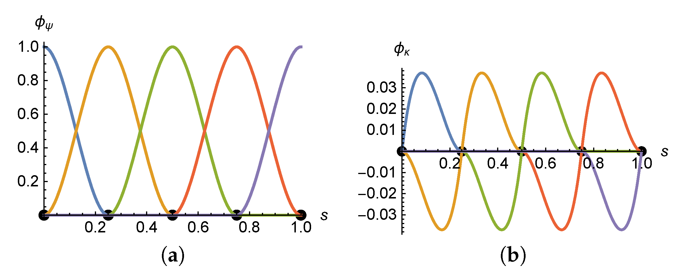
where ϕ ψ 1 , ϕ ψ 2 , , ϕ ψ n , ϕ κ 1 , , ϕ ψ n are Lagrange polynomials in H 2 [21], satisfying 0 ( ϕ ψ j ) 2 d s < and 0 ( ϕ κ j ) 2 d s < for all j, so that the integrals in (25) involving second derivatives ψ i are well defined. On the other hand, ϕ τ 1 , , ϕ τ n is a set of Lagrange polynomials in H 1 [21], satisfying 0 ( ϕ τ j ) 2 d s < so that the weak form of the system is well posed. Coefficient sets a i 1 , , a i n , b i 1 , , b i , n , and c i 1 , , c i n are the unknown time varying amplitudes, which equal the approximate solution evaluated at the node locations due to the interpolating properties of Lagrange polynomials:
ϕ ψ j ( s i k ) = 1 , k = j 0 , k j , ϕ ψ j ( s i k ) = 0 , j , k = 1 , , n
ϕ κ j ( s i k ) = 1 , k = j 0 , k j , ϕ κ j ( s i k ) = 0 , j , k = 1 , , n
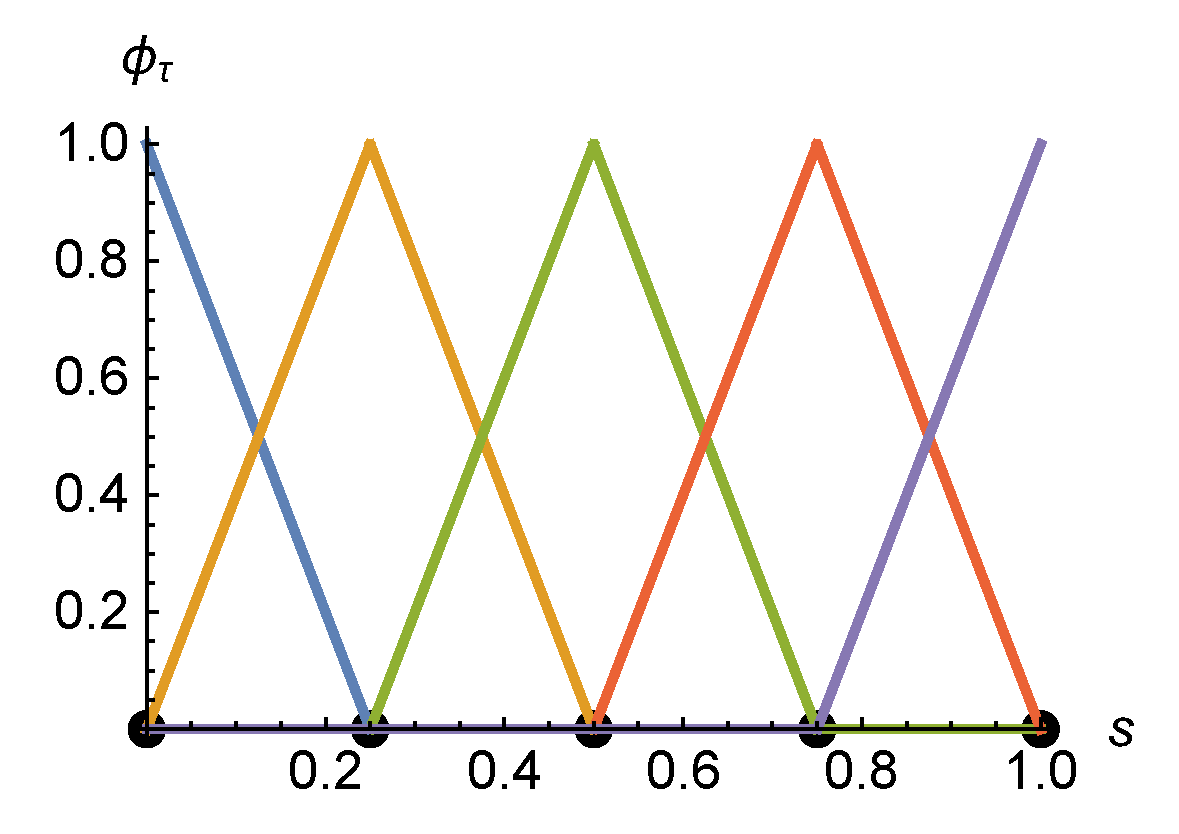
ϕ τ j ( s i k ) = 1 , k = j 0 , k j , j , k = 1 , , n
so that ψ i ( s i k ) = a i k , ψ i ( s i k ) = b i k , and τ i ( s i k ) = c i k . Example plots of the adopted basis functions are given in the Appendix B. By substituting the projections (35) into the weak form (35), we obtain the finite element discrete form:
ρ M q ¨ + ζ M q ˙ + ρ C ( q ˙ ) + K c q + F ( q ) + U = 0
where q = a 1 , b 1 , , a N , b N , c 1 , , c N is the collection of all unknowns for the coupled system, of dimension 3 n N n ¯ , where n ¯ is the total number of kinematic constraints, that is the number of constraints on ψ i , κ i , and τ i , i = 1 , , N . The 3 n N n ¯ × 3 n N n ¯ matrix M and the 3 n N n ¯ nonlinear operator C have the block structure:
M = M ψ 0 0 0 , C = 0 C τ
with the details given in Appendix C. The matrix K c has the block structure:
K c = K c ψ 0 0 K c τ
and details can be found in Appendix C. The 3 n N n ¯ input vector U = U 1 , , U N depends on the actuation actions in (31) and (34), with entries given by:
U i ( t ) = μ ¯ i ( t ) ϕ ψ ( 0 ) + ν ¯ i ( t ) ϕ κ ( 0 ) θ ¯ i ( t ) ϕ τ ( 0 )
The operator F , mapping to a 3 n N n ¯ vector, accounts for the nonlinear dynamics of the filaments. It has the block structure:
F = F ψ 1 F κ 1 F τ 1 F ψ N F κ N F τ N T
with entries determined by the integral terms of the weak form (25) as detailed in Appendix C.

4. Simulation Results and Discussion

Finite element simulation results were obtained for the following set of material and geometric parameters: = 1 m, ρ = 1 kg m−1, ζ = 0.5 kg m−1 s−1, k M = 10   k g × m 3 / s 2 , α ν = 20 N m−1, α μ = 5   N , and α τ = 1   m −1. The final time for numerical integration was t f = 20   s , and a system of four coupled filaments was considered.
Each filament was discretized by five uniformly placed nodes in [ 0 , ] , and the resulting nonlinear system of ODEs (37) was integrated with the Mathematica built-in nonlinear solver NDSolve, which uses multi-step methods with local error convergence control and adaptive time steps. The absolute and relative error control precision parameters in NDSolve are respectively AccuracyGoal and PrecisionGoal. The two parameters are set by default to half the machine precision, which in the case of the results calculated here was 16 digits.
The boundary conditions τ i ( L , t ) = 0 , i = 1 , , N are essential or kinematic since the tension τ is a state variable and are enforced by removing the N degrees of freedom c i n ( t ) , i = 1 , , N . For the boundaries at s i = 0 , we considered two types of coupling:
  • Rotation coupling, defined by the boundary conditions:
    κ i ( 0 , t ) = ψ i ( 0 , t ) = 0 b i 1 ( t ) = 0 , i = 1 , , N
    and generalized moment μ i given by (31).
  • Curvature coupling, defined by the boundary conditions:
    ψ i ( 0 , t ) = 0 a i 1 ( t ) = 0 , i = 1 , , N
    and generalized normal force ν i given by (34).
In both cases, the kinematic boundary conditions remove N degrees of freedom. Therefore, the discrete system of nonlinear ODEs (37) has dimension N ( 3 n 2 ) = 13 N for n = 5 nodes. In both cases, the set of boundary conditions at s i = 0 is completed with the coupling in the dual of the tension:
θ i ( 0 , t ) = α τ j = 1 N σ i j ( t ) τ j ( 0 , t ) τ i ( 0 , t )
Coupling coefficients σ i j are set as in (32) to induce direct coupling among contiguous filaments. Future research developments include modelling with evolving coupling coefficients. Actuation inputs were set to:
μ ¯ i ( t ) = sin 3 t , i = 3 0 , i 3
with the same setting adopted for ν ¯ i . All initial conditions were set to zero. The internal forces f i were also set to zero for the purpose of simulation to isolate the effect of the basal coupling. The plots in Figure 4 show the evolution of the four tip displacements r i ( , t ) , which exhibited an oscillatory behaviour induced by the actuation. For the same set of parameters, there were clear differences in the responses induced by the two types of couplings, where the transmissibility of oscillatory patterns was visibly more attenuated in the case of rotation coupling.
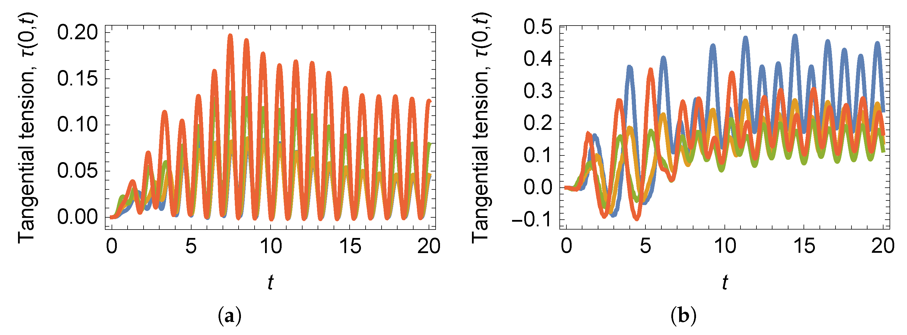
The evolution of the tangential tension at the attachment with the base are shown in Figure 5, where oscillatory patterns emerge due to the actuation in terms of the generalized transverse force or generalized moment.
Three snapshots of the configurations of the array of four filaments are shown in Figure 6 and Figure 7, respectively for rotation and for curvature coupling. Considering that the two coupling conditions were simulated with the same set of material and geometric parameters, it is interesting to note how different beating patterns can be generated by controlling the actuation and the coupling. In this specific case, rotation coupling resulted in nearly rigid body rotation of the filaments, whereas with curvature coupling, there was much more pronounced bending. This has implications for the design, hinting at the possibility of inducing different modes of operation by controlling the input and the type of coupling, without necessarily changing the material and geometric properties of the system.

5. Conclusions

A model for an array of stiff filaments with basal coupling was presented. The filaments’ model was based on some features of arrays of cilia ubiquitously observed in small-scale mobile biological structures. These structures evolved desirable properties for robotic locomotion adapted to uncertain, unstructured environments, specifically in terms of robustness and versatility to different types of terrain and substrates.
The nonlinear model of the system was numerically solved with finite elements, and simulation results were compared for two types of basal coupling. Oscillatory beating patterns were induced with minimal actuation of one filament through coupling. For the same set of parameters, different coupling induced beating patterns with considerably different shapes, hinting at the possibility of controlling the operation modes through coupling modes.
Future work will address quantitatively the wave propagation associated with collective beating and synchronous and metachronal modes induced by basal coupling.

Funding

This research received no external funding.

Conflicts of Interest

The author declares no conflict of interest.

Appendix A

Different integrations by parts are performed to reduce the maximum order of the spatial derivation to two, so that the finite element formulation involves polynomial basis functions of minimal order of regularity [21]:
0 k M ψ i I V ψ ˜ i d s i = 0 k M ψ i ψ ˜ i d s i + k M ψ i ψ ˜ i ψ i ψ ˜ i 0
0 a f i ψ ˜ i d s i = 0 a f i ψ ˜ i d s i + a f i ψ ˜ i a f i ψ ˜ i 0
0 τ i ψ i ψ ˜ i d s i = 0 ψ i τ i ψ ˜ i d s i τ i ψ i ψ ˜ i 0
0 τ i τ ˜ i d s i = 0 τ i τ ˜ i d s i + τ i τ ˜ i 0
0 2 ψ i ( k M ψ i a f i ) τ ˜ i d s i = 0 2 ( k M ψ i a f i ) ψ i τ ˜ i d s i + 2 ψ i ( k M ψ i a f i ) τ ˜ i 0

Appendix B

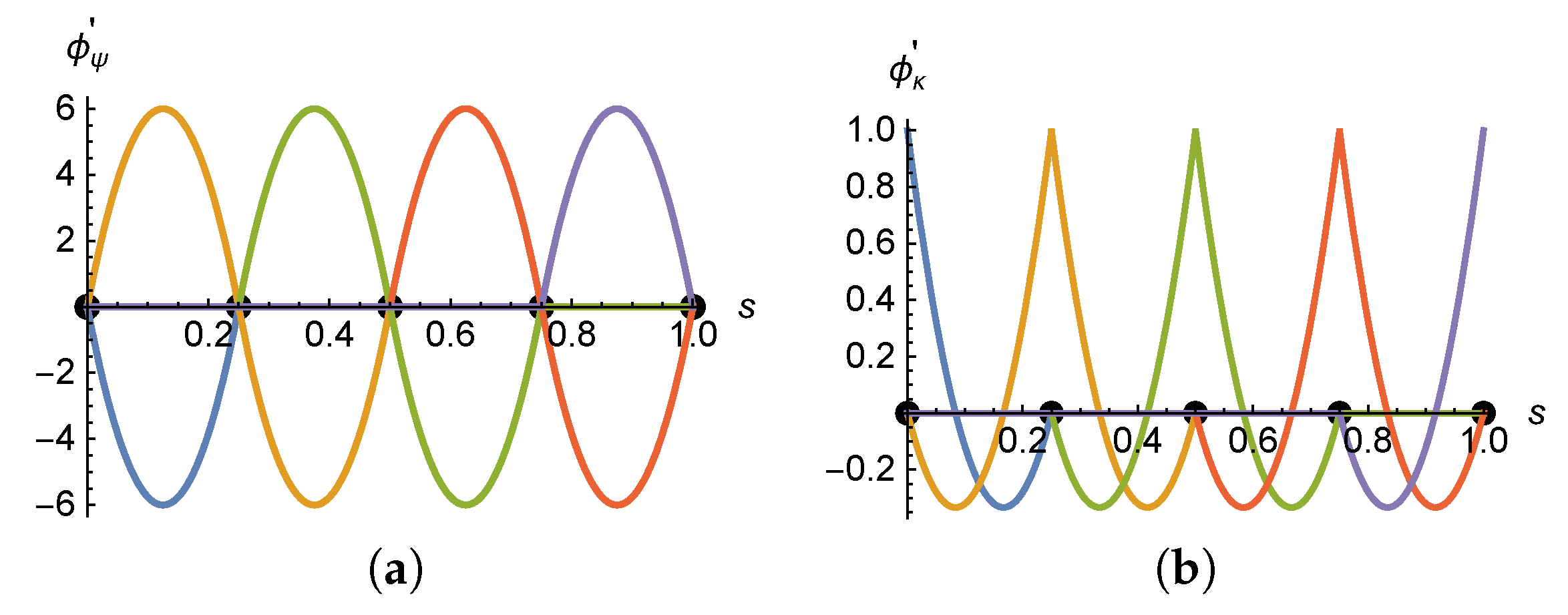
For a mesh of five uniformly spaced nodes in the domain [ 0 , 1 ] , the following plots show the basis functions ϕ ψ and ψ κ and their derivatives. The functions are constructed by imposing the constraints (36).
Figure A1. Sets of H 2 finite element basis functions (a) ϕ ψ j and (b) ψ κ j , j = 1 , , 5 .
Mathematics 08 01282 g0a1
Figure A2. Sets of H 2 finite element basis function derivatives (a) ϕ ψ j and (b) ψ κ j , j = 1 , , 5 .
Mathematics 08 01282 g0a2
Basis functions ϕ τ are plotted in Figure A3.
Figure A3. Sets of H 1 finite element basis function ϕ τ j , j = 1 , , 5 .
Mathematics 08 01282 g0a3

Appendix C

Entries of different matrices appearing in the finite element discrete formulation. Matrix M :
M ψ = diag m ψ 1 , , m ψ N , m ψ i = 0 ϕ ψ T ϕ ψ d s i 0 ϕ ψ T ϕ κ d s i sym 0 ϕ κ T ϕ κ d s i , i = 1 , , N
Nonlinear operator C with Coriolis terms:
C τ i ( q ˙ ) = 0 ϕ ψ ( s i ) a ˙ i ( t ) + ϕ κ ( s i ) b ˙ i ( t ) 2 ϕ τ T d s i ,
C τ = C τ 1 C τ N T
Coupling matrix K c : If the coupling is through the dual of the rotation, (31) gives:
K c ψ = k ψ 11 k ψ 1 N k ψ N 1 k ψ N N , k ψ i i = α ν j = 1 N σ i j ( t ) ϕ ψ T ( 0 ) ϕ ψ ( 0 ) ϕ ψ T ( 0 ) ϕ κ ( 0 ) sym ϕ κ T ( 0 ) ϕ κ ( 0 ) , k ψ i j = α ν σ i j ( t ) ϕ ψ T ( 0 ) ϕ ψ ( 0 ) ϕ ψ T ( 0 ) ϕ κ ( 0 ) sym ϕ κ T ( 0 ) ϕ κ ( 0 ) , j i , K c τ = k τ 11 k τ 1 N k τ N 1 k τ N N ,
k τ i i = α τ j = 1 N σ i j ( t ) ϕ τ T ( 0 ) ϕ τ ( 0 ) , k τ i j = α τ σ i j ( t ) ϕ τ T ( 0 ) ϕ τ ( 0 ) , i j
If the filaments are coupled in curvature, (34) gives:
k ψ i i = α μ j = 1 N σ i j ( t ) ϕ ψ T ( 0 ) ϕ ψ ( 0 ) ϕ ψ T ( 0 ) ϕ κ ( 0 ) sym ϕ κ T ( 0 ) ϕ κ ( 0 ) , k ψ i j = α μ σ i j ( t ) ϕ ψ T ( 0 ) ϕ ψ ( 0 ) ϕ ψ T ( 0 ) ϕ κ ( 0 ) sym ϕ κ T ( 0 ) ϕ κ ( 0 ) , j i
Entries of the nonlinear internal dynamics vector F :
F ψ i ( q , q ˙ ) = 0 ν i ( s i , q ) ϕ ψ T d s i + 0 ν i ( s i , q ) ϕ ψ ( s i ) a i ( t ) + ϕ κ ( s i ) b i ( t ) 2 ϕ ψ T d s i 0 ϕ τ ( s i ) c i ( t ) ϕ ψ ( s i ) a i ( t ) + ϕ κ ( s i ) b i ( t ) ϕ ψ T d s i + 0 ϕ τ ( s i ) c i ( t ) ϕ ψ ( s i ) a i ( t ) + ϕ κ ( s i ) b i ( t ) ϕ ψ T d s i
F κ i ( q , q ˙ ) = 0 ν i ( s i , q ) ϕ κ T d s i + 0 ν i ( s i , q ) ϕ ψ ( s i ) a i ( t ) + ϕ κ ( s i ) b i ( t ) 2 ϕ κ T d s i 0 ϕ τ ( s i ) c i ( t ) ϕ ψ ( s i ) a i ( t ) + ϕ κ ( s i ) b i ( t ) ϕ κ T d s i + 0 ϕ τ ( s i ) c i ( t ) ϕ ψ ( s i ) a i ( t ) + ϕ κ ( s i ) b i ( t ) ϕ κ T d s i
F τ i ( q , q ˙ ) = 0 ν i ( s i , q ) ϕ ψ ( s i ) a i ( t ) + ϕ κ ( s i ) b i ( t ) ϕ τ T + 2 ϕ ψ ( s i ) a i ( t ) + ϕ κ ( s i ) b i ( t ) ϕ τ T d s i 0 ϕ τ ( s i ) c i ( t ) ϕ ψ ( s i ) a i ( t ) + ϕ κ ( s i ) b i ( t ) 2 ϕ τ T + ϕ τ ( s i ) c i ( t ) ϕ τ T d s i
for i = 1 , , N , where:
ν i ( s i , q ) = k M ϕ ψ ( s i ) a i ( t ) + ϕ κ ( s i ) b i ( t ) a f i ( a i , b i )

References

  1. Camalet, S.; Jülicher, F. Generic Aspects of Axonemal Beating. New J. Phys. 2000, 2, 24. [Google Scholar] [CrossRef]
  2. Srigiriraju, S.V.; Powers, T.R. Model for Polymorphic Transitions in Bacterial Flagella. Phys. Rev. E 2006, 73, 011902. [Google Scholar] [CrossRef] [PubMed] [Green Version]
  3. Dillon, R.H.; Fauci, L.J.; Omoto, C. Mathematical Modeling of Axoneme Mechanics and Fluid Dynamics in Ciliary and Sperm Motility. Dyn. Contin. Discret. Impuls. Syst. Ser. A Math. Anal. 2003, 10, 745–757. [Google Scholar]
  4. Riedel-Kruse, I.H.; Hilfinger, A.; Howard, J.; Juelicher, F. How Molecular Motors Shape the Flagellar Beat. HFSP J. 2007, 1, 192–208. [Google Scholar] [CrossRef] [PubMed] [Green Version]
  5. Pellicciotta, N.; Hamilton, E.; Kotar, J.; Faucourt, M.; Delgehyr, N.; Spassky, N.; Cicuta, P. Entrainment of Mammalian Motile Cilia in the Brain with Hydrodynamic Forces. Proc. Natl. Acad. Sci. USA 2020, 117, 8315–8325. [Google Scholar] [CrossRef] [PubMed] [Green Version]
  6. Saleem, N.; Munawar, S. Entropy Analysis in Cilia Driven Pumping Flow of Hyperbolic Tangent Fluid with Magnetic Field Effects. Fluid Dyn. Res. 2020, 52, 025503. [Google Scholar] [CrossRef]
  7. Hall, J.; Clarke, N. The Mechanics of Cilium Beating: Quantifying the Relationship between Metachronal Wavelength and Fluid Flow Rate. J. Fluid Mech. 2020, 891, A20. [Google Scholar] [CrossRef]
  8. Oldenburg, A.L.; Chhetri, R.K.; Hill, D.B.; Button, B. Monitoring Airway Mucus Flow and Ciliary Activity with Optical Coherence Tomography. Biomed. Opt. Express 2012, 3, 1978–1992. [Google Scholar] [CrossRef] [PubMed] [Green Version]
  9. Dasgupta, A.; Amack, J.D. Cilia in Vertebrate Left–Right Patterning. Philos. Trans. R. Soc. B Biol. Sci. 2016, 371. [Google Scholar] [CrossRef] [PubMed] [Green Version]
  10. Niedermayer, T.; Eckhardt, B.; Lenz, P. Synchronization, Phase Locking, and Metachronal Wave Formation in Ciliary Chains. Chaos 2008, 18, 037128. [Google Scholar] [CrossRef] [PubMed]
  11. Elgeti, J.; Gompper, G. Emergence of Metachronal Waves in Cilia Arrays. Proc. Natl. Acad. Sci. USA 2013, 110, 4470–4475. [Google Scholar] [CrossRef] [PubMed] [Green Version]
  12. Elshalakani, M.; Bruecker, C. Simulation of Self-Coordination in a Row of Beating Flexible Flaplets for Micro-Swimmer Applications: Model and Experiment Study. J. Fluids Struct. 2020, 94, 102923. [Google Scholar] [CrossRef]
  13. Wan, K.Y.; Goldstein, R.E. Coordinated Beating of Algal Flagella Is Mediated by Basal Coupling. Proc. Natl. Acad. Sci. USA 2016, 113, E2784–E2793. [Google Scholar] [CrossRef] [Green Version]
  14. Bogue, R. Robots for Monitoring the Environment. Ind. Robot Int. J. 2011, 38, 560–566. [Google Scholar] [CrossRef]
  15. Wang, Z.; Gu, H.; Reddy, H.A.; Kalyan, B.; Murthy, C.S.N. Mine Rescue Robot System—A Review. Procedia Earth Planet. Sci. 2015, 11, 457–462. [Google Scholar] [CrossRef] [Green Version]
  16. Bangalkar, Y.V.; Kharad, S.M. Review Paper on Search and Rescue Robot for Victims of Earthquake and Natural Calamities. Int. J. Recent Innov. Trends Comput. Commun. 2015, 3, 2037–2040. [Google Scholar] [CrossRef]
  17. Thavasi, P.T.; Suriyakala, C.D. Sensors and Tracking Methods Used in Wireless Sensor Network Based Unmanned Search and Rescue System—A Review. Procedia Eng. 2012, 38, 1935–1945. [Google Scholar] [CrossRef] [Green Version]
  18. Trevelyan, J.P.; Kang, S.C.; Hamel, W.R. Robotics in Hazardous Applications. In Springer Handbook of Robotics; Siciliano, B., Khatib, O., Eds.; Springer: Berlin/Heidelberg, Germany, 2008; pp. 1101–1126. [Google Scholar]
  19. Hilfinger, A.; Jülicher, F. The Chirality of Ciliary Beats. Phys. Biol. 2008, 5, 016003. [Google Scholar] [CrossRef] [PubMed] [Green Version]
  20. Goldstein, R.E.; Langer, S.A. Nonlinear Dynamics of Stiff Polymers. Phys. Rev. Lett. 1995, 75, 1094–1097. [Google Scholar] [CrossRef] [Green Version]
  21. Hughes, T.J. The Finite Element Method: Linear Static and Dynamic Finite Element Analysis; Dover Publications: Mineola, NY, USA, 2000. [Google Scholar]
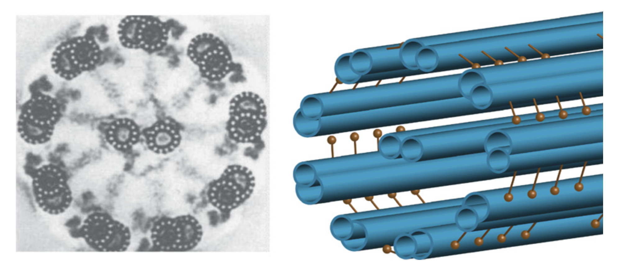
Figure 1. Cross-sectional image and schematic of an axonemal structure (reproduced from [19] with the author’s permission).
Mathematics 08 01282 g001
Figure 2. Geometric model of an axonemal structure.
Mathematics 08 01282 g002
Figure 3. Schematics of the concept of basal coupling among contiguous filaments.
Mathematics 08 01282 g003
Figure 4. Evolution of the tip displacement: (a) rotation coupling and (b) curvature coupling. The response of the actuated filament is the one in green.
Mathematics 08 01282 g004
Figure 5. Evolution of the tension τ at the base: (a) rotation coupling and (b) curvature coupling. The response of the actuated filament is the one in green.
Mathematics 08 01282 g005
Figure 6. Three snapshots of the configuration of the array of four coupled filaments with rotation coupling. Time (a) t = 7   s ; (b) t = 10   s ; and (c) t = 15   s .
Mathematics 08 01282 g006
Figure 7. Three snapshots of the configuration of the array of four coupled filaments with curvature coupling. Time (a) t = 7   s ; (b) t = 10   s ; and (c) t = 15   s .
Mathematics 08 01282 g007