Article

Bending Analysis of Functionally Graded Nanoscale Plates by Using Nonlocal Mixed Variational Formula

1
Department of Mathematics, Faculty of Science, King Abdulaziz University, P.O. Box 80203, Jeddah 21589, Saudi Arabia
2
Department of Mathematics, Faculty of Science, Kafrelsheikh University, Kafrelsheikh 33516, Egypt
3
Department of Mathematics, Faculty of Science, King Khaled University, Abha 21589, Saudi Arabia
4
Department of Mathematics and Statistics, Higher Institute of Management and Information Technology, Nile for Science and Technology, Kafrelsheikh 33514, Egypt
*
Author to whom correspondence should be addressed.
Mathematics 2020, 8(7), 1162; https://doi.org/10.3390/math8071162
Submission received: 11 June 2020 / Revised: 27 June 2020 / Accepted: 10 July 2020 / Published: 15 July 2020
(This article belongs to the Special Issue Applied Mathematical Methods in Mechanical Engineering)

Abstract

:
This work is devoted to the bending analysis of functionally graded (FG) nano-scale plate by using the nonlocal mixed variational formula under simply supported edge conditions. According to Eringen’s nonlocal elasticity theory, the mixed formula is utilized in order to obtain the governing equations. The system of equations is derived by using the principle of virtual work. The governing equations include both the small and the mechanical effects. The impact of the small-scale parameter, aspect and thickness nano-scale plate ratios, and gradient index on the displacement and stresses are explored, numerically presented, and discussed in detail. Different comparisons are made to check the precision and validity of the bending outcomes obtained from the present analysis of FG nano-scale plates. Parametric examinations are then performed to inspect the impacts of the thickness of the plate on the by and large mechanical reaction of the practically evaluated plates. The displayed outcomes are valuable for the configuration procedures of keen structures and examination from materials.

1. Introduction

The nanotechnology methods in a variety of applications—for instance, microsurgery provided by Lebaschi et al. [1]; nano-sensors, nano-composites, and smart structures and systems presented by Johnson et al. [2]; cell manipulation studied by Jandaghian and Rahmani [3]—are used in the manufacture of most new devices and materials. Recently, there has been increased attention from scholars regarding the study of micro/nano basic elements like plates and beams and plates at the micro/nano-length scale. The regular use of continuum models in the investigation of these factors, in which size affects simulations, is attributed to the costly molecular and atomic simulations studied by Şimşek [4].
In capturing the size effects of these structures with regard to the relationships between the non-adjacent molecules and atoms, high order continuum theories are applied to model micro/nano-scale structures. Nonlocal elasticity is the most regularly applied continuum mechanics theory for modeling nano-structures. Eringen [5] developed a nonlocal elasticity theory which is applied to the modeling of long-range relationships between atoms. Eringen’s nonlocal theory emphasizes that a specific point interacts with the strains at all points within the continuum body, not just with those close to the given point. Then, Eringen [5] developed the differential constitutive theory, which confirmed that a specific form of Kernel operation of the nonlogical integral constitutive interaction could be changed into various types, which could be resolved much more simply in comparison to the central model. Later, in the bounded continuous structural model, they applied the differential formulation presented by Peddieson et al. [6]. Nevertheless, they neglected the fact that the constitutive boundary conditions on the stress appear naturally when operating with the bounded domains [7,8,9,10].
Functionally graded materials (FGMs) refer to non-homogeneous composites that feature continuous and smooth variants in both the material’s features and the compositional profile, which permit its wide use in most engineering devices. The usage of FG materials creates an even distribution of stress in the structures and offers solutions to issues like jump in factors of stress within matrix cracking, interfacial debonding, layers, etc. The dynamics analyses of plates and beams in the last decade have attracted many studies on FGMs. Classical plate theory (CPT), or the Kirchhoff plate theory, is the most famous theory for investigating plates’ mechanical behavior. Zhang and Zhou [11] investigated deflection analysis, free vibration, and buckling of the thin FG plates depending on the physical neutral surface, in accordance with this theory. In the case of nonlinear free vibrational behavior in the square FG’s thinner plates, Woo et al. [12] offered an analytical solution through the von Karman theory. In the study by Yang and Shen [13], the response dynamic of the former was operationally emphasized by a rectangular FG’s thin plates under the partially distributed impulsive lateral loads lying on or in the absence of an elastic foundation. However, even though CPT is suitable for thin plates, it provides inaccurate solutions for thick plates due to the neglect of normal and shear deformation in the classical plate theory. Several scholars have recommended varying higher-order shear deformation theories, which cover normal and shear deformation. Unlike any other theory, there are only four unknown functions included, compared to five in the case of other theories of shear deformation. Hebali et al. [14] has developed a new quasi-three-dimensional (3D) hyperbolic shear deformation for the analysis of the free vibration and bending of the FG plates. Furthermore, Mahi et al. [15] studied an advanced hyperbolic shear deformation theory which can be used for free vibration and bending analyses of FG, isotropic, laminated composite plates and sandwich. Couple-stress and surface elasticity theory, strain gradient theory, and nonlocal theory are the most important theories [16,17,18,19].
Of these popular theories, Eringen’s theory [20,21] has a broad use in the study of the nano-structures’ mechanical behavior because of its high accuracy and simplicity. These investigations confirmed that the findings from this theory were consistent with the findings from the molecular dynamic and experimental techniques [22,23,24,25,26,27,28,29]. Ahouel et al. [30] created a nonlocal trigonometric shear deformation theory depending on the neutral surface position for the vibration, buckling, and bending of FG nanorods through the nonlocal differential constitutive interaction with Eringen. This model can capture both transverse shear deformation impacts and small-scale impacts of the FG nanobeams, hence there is no need for shear correction factors.
The mixed first-order shear deformation plate theory (MFPT) is an amendment of the simple first-order shear deformation plate theory (SFPT). The primary displacement assumptions for Reissner–Mindlin’s traditional SFPT are retained. In the MFPT, both the stresses and displacements should be considered arbitrary. Thus, the researcher must apply a mixed variational formulation [31,32,33]. The development of MFPT depends on a mixed variational formulation that assumes that, throughout the plate’s thickness, there is a continuous distribution of stress. Additionally, the surface condition is consistent with the transverse shear stresses. Hence, the rationale for the shear correction factor rationale necessary for the SFPT is precluded. Furthermore, they consider the impact of transverse normal stress. In a very recent study, Zenkour [31,32,33] presented a correlation between the mixed and simple first-order theories of transverse shear deformation. Then, he developed an analytical solution for buckling loads, natural frequencies, and stress analysis in anisotropic plates and shells under numerous boundary conditions.
This article marks the first attempt to study the bending of an FG orthotropic nano-scale plate depending on the nonlocal mixed variational formula. The assumption is that the entire FG orthotropic nanoplate edges are simply supported. Through Eringen’s nonlocal elasticity theory, they derive the guiding differential equations. These governing equations consist of the mechanical and the small-scale parameter. Then, this paper derives the analytical solutions for the bending response of simply supported FG orthotropic nano-scale plate. In addition, it investigates the impact of the plate’s aspect ratio, gradient index, side-to-thickness ratio, and nonlocal parameter on the stress and displacement.

2. Functionally Graded (FG) Orthotropic Nanoplates

A simply supported orthotropic nano-scale plate can be considered as having a length a , width b , and thickness h made of FG material. As specified in Figure 1, the FG orthotropic nano-scale plate is subjected to an applied sinusoidally distributed transverse load q ( x , y ) . It is supposed that the material properties of the FG differ in thickness with respect to the distribution of power law. It is expected that effective material properties P ( z ) like Young’s modulus continuously differ within the depth direction, according to the power law. Suppose that the FG orthotropic nano-scale plate is finished by mixing two contrasting material phases—for instance, ceramic and metal—and are stated as the following:
P ( z ) = P m + ( P c P m ) V f
where P ( z ) , P c , and P m are, respectively, the effective material property, bottom surface property, and upper surface property of the FG nanoplate. V f is the volume fraction of the FGM. The effective material properties of the FG nano-scale plate are distinguished by the power law distribution, based on the following formula by Zenkour [34]. The volume fraction of the FG gradient material V f is supposed to be assumed by
V f = ( 1 2 + z h ) k ,   k 0 ,
where k is the index of the power law. When k is equal to zero, the plate is fully ceramic, and when k is infinity, it is fully metal. Therefore, the material properties may be written as follows:
P ( z ) = P m + ( P c P m ) ( 1 2 + z h ) k .
The material gradient (Young’s modulus E ( z ) and shear modulus G ( z ) through the plate thickness) of the orthotropic FG nanoplate is supposed to show due to the power law variation. Hence, the Young’s and shear moduli can be expressed as a power function of z (Asghari et al. [17]), as given in Equation (3).

3. Nonlocal Mixed Formula for FG Orthotropic Nanoplates

According to the nonlocal elasticity that was developed by Eringen, the stresses at a point such as x are dependent on the strains of all other points x of the domain. After which, Eringen recommended a constitutive model which represents the nonlocal stress components σ i j as the following:
σ i j = V α ( | x x | , τ ) c i j k l ε k l ( x ) d V ,
and
ε i j = 1 2 ( u i , j + u j , i )   ,
where σ i j , ε i j , and u i are the stress, strain, and displacement components, respectively; c i j k l is the fourth-order elasticity tensor; | x x | represents the distance (in Euclidean norm) and α ( | x x | , τ ) is the nonlocal modulus. τ = e 0 a / l is the scale coefficient, which is inclusive of the small-scale factor. e 0 represents a material constant either estimated or experimentally obtained through the corresponding dispersion curves of the plane waves with those for the atomic lattice dynamics. l represents external characteristic lengths and a represents the internal length for the nanostructures. In accordance with Eringen, one can be simply the constitutive Equation (4) to the similar form of the differential constitutive equation, as shown below [35].
( 1 μ 2 ) σ i j = a i j k l 1 ε k l ,
where μ = ( e 0 l ) 2 and e 0 l are the nonlocal parameters, while 2 represents the Laplace operator, inclusive of the small-scale impact into the nano-structure’s constitutive equations.

4. Formulations of the Problem

The displacements of an arbitrary point along the x -, y -, and z -axes can be written as in Zenkour [31]:
u 1 ( x , y , z ) = u ( x , y ) + z φ x ( x , y ) , u 2 ( x , y , z ) = v ( x , y ) + z φ y ( x , y ) , u 3 ( x , y , z ) = w ( x , y ) ,  
where u , v , and w are the displacements in the directions of x , y , and z , respectively; φ x and φ y are the rotations of the normal to mid-plane of the nanoplate about the y and x axes, respectively.
The strains related to the displacements in Equation (7) are
ε x x = ε x x 0 + z ε x x 1 ,   ε y y = ε y y 0 + z ε y y 1 , ε y z = ε y z 0 ,   ε x z = ε x z 0 ,   ε x y = ε x y 0 + z ε x y 1 ,
where
ε x x 0 = u x ,   ε x x 1 = φ x x ,   ε y y 0 = v y ,   ε y y 1 = φ y y , ε y z 0 = φ y + w y ,   ε x z 0 = φ x + w x ,   ε x y 0 = u y + v x ,   ε x y 1 = φ y x + φ x y ,
in which the displacement fields and stress for MFPT are considered to be arbitrary. Then, an assumption is made about the stress field that takes the form of Zenkour [31]:
σ i j = G i j ( 0 ) ( x , y ) + z G i j ( 1 ) ( x , y ) , σ i z = G i z ( 0 ) ( x , y ) [ 1 ( z h / 2 ) 2 ] , σ z z = r = 1 4 z r 1 G z ( r ) ( x , y ) , i , j = x , y .  
The functions G i j ( 0 ) , G i j ( 1 ) , and G i z ( 0 ) are assumed to be obtained from the point of the stresses, as in the following:
{ N i j ,   M i j } = h / 2 h / 2 σ i j { 1 , z } d z , { Q i z } = h / 2 h / 2 { σ i z } d z , i = x , y ,
where N i j , M i j , and Q i z are, respectively, the axial force, bending moment, and shear force resultants.
In addition, the functions G z ( r ) are assumed to be obtained from the point where the transverse normal stress σ z z satisfies the conditions below:
σ z z | z = h 2 = q , σ z z | z = h 2 = 0 , h 2 h 2 σ z z d z = 0 , h 2 h 2 z σ z z d z = 0 .
According to the mixed formula, the final expressions for the stress components are given as the following:
σ i j = N i j h + 12 M i j h 3 z , σ i z = 3 Q i z h [ 1 ( z h / 2 ) 2 ] , σ z z = q 4 [ 1 2 ( z h / 2 ) 5 ( z h / 2 ) 2 ] ( 1 z h / 2 ) , i , j = x , y .  
The potential energy Π U of the FG nano-scale plate is given by
h / 2 h / 2   Ω δ Π U d Ω d z = h / 2 h / 2   Ω σ i j δ ε i j d Ω d z .
Substituting Equations (8) and (9) into Equation (14) yields the following:
h 2 h 2   Ω δ Π U d Ω d z = Ω [ N x x δ u x + N y y δ v y + N x y ( δ v x + δ u y ) + M x x δ φ x x + M y y δ φ y y + M x y ( δ φ y x + δ φ x y ) + Q y z ( δ φ y + δ w y ) + Q x z ( δ w x + δ φ x ) ] d Ω ,
The work done by external force Π W can be written as the following:
h / 2 h / 2   Ω δ Π W d Ω   d z = Ω q δ w d Ω .
The equilibrium equations are assumed to be obtained by using the principle of virtual work. These equations are given as
t 1 t 2   Ω δ ( Π U Π W ) d Ω   d t = 0 .
In the case of the MFPT, the equilibrium equations can be stated in the following form:
t 1 t 2 [ h / 2 h / 2   Ω ( δ ( σ i j ε i j ) δ Π R ) d Ω   d z + δ Π W ] d t = 0 ,
where Π R represents the complementary energy density, which can be defined as follows:
Π R = 1 2 [ a 11 σ x x 2 + a 22 σ y y 2 + a 33 σ z z 2 + a 44 τ y z 2 + a 55 τ x z 2 + a 66 τ x y 2 ] + a 12 σ x x σ y y + a 23 σ y y σ z z + a 13 σ x x σ z z .
Then, the coefficients a i j represent compliances for the orthotropic FG plate and are expressed as follows:
a 11 = 1 E 1 ( z )   , a 22 = 1 E 2 ( z )   , a 33 = 1 E 3 ( z )   , a 12 = ν 12 E 1 ( z ) = ν 21 E 2 ( z )   , a 44 = 1 G 23   , a 55 = 1 G 13   , a 66 = 1 G 12   .
The governing equations could be acquired through Equation (16) and the integration for the parts, followed by equating the coefficients of δ u , δ v , δ w , δ φ x , and δ φ y to zero. Specifically, the correlation between the equilibrium equations and the present theory is determined as the following:
N x x x + N x y y = 0 , N x y x + N y y y = 0 ,   M x x x + M x y y Q x z = 0 , M x y x + M y y y Q y z = 0 , Q x z x + Q y z y + ( 1 μ 2 ) q = 0 ,
The nonlocal stress and moment resultants can be written as [35] follows:
N x x ( 1 μ 2 ) = A 11 u x + A 12 v y , N y y ( 1 μ 2 ) = A 12 u x + A 22 v y , N x y ( 1 μ 2 ) = A 66 v x + A 66 u y , M x x ( 1 μ 2 ) = D 11 φ x x + D 12 φ y y , M y y ( 1 μ 2 ) = D 12 φ x x + D 22 φ y y , M x y ( 1 μ 2 ) = D 66 φ y x + D 66 φ x y , Q y z ( 1 μ 2 ) = A 44 φ y + A 44 w y ,   Q x z ( 1 μ 2 ) = A 55 w x + A 55 φ x ,
where the undefined quantities are given by
[ A 11 A 12 A 12 A 22 ] = h [ a 11 a 12 a 12 a 22 ] 1 , A 66 = h a 66 , A r r = 5 h 6 a r r , D i j = h 2 12 A i j , ( r = 4 , 5   ; i , j = 1 , 2 , 6 )   .

5. Exact Solution

In the present study, the considered the FG nano-scale plate has all the edges simply supported. The exact solution of Equation (20) can be obtained analytically through applying the boundary conditions stated below:
v = w = φ y = N x x = M x x = 0 at x = 0 , a , u = w = φ x = N y y = M y y = 0 at y = 0 , b .
The mechanical load q can be expressed as
q = m , n = 1 , 3 , 5 , q m n sin ( α x ) sin ( β y ) ,
where α = m π / a and β = n π / b , and m and n are called mode numbers. For a uniformly distributed load, the coefficients q m n = 16 q 0 / m n π 2 . According to a sinusoidally distributed load, q m n = q 11 = q 0 , where q 0 represents the intensity of the mechanical load. Employing Navier’s type solution, the displacements and rotations u , v , w , φ x , and φ y , which meet the boundary conditions, should be as follows:
{ ( u , φ x ) ( v , φ y ) w } = m , n = 1 , 3 , 5 , { ( U , X ) cos ( α x ) sin ( β y ) ( V , Y ) sin ( α x ) cos ( β y ) W sin ( α x ) sin ( β y ) } ,
in which U , V , W , X , and Y are arbitrary parameters which will be determined. Through Equations (20)–(25), in Equation (20), the following equation is obtained:
[ L ] { Δ } = { F } ,
where { Δ } and { F } are given by the following:
{ Δ } = { U ,   V , W , X , Y } T , { F } = { 0 , 0 , ( 1 μ 2 ) q 0 , 0 , 0 } T .
In addition, the symmetric nonzero components of framework [ L ] are defined as follows:
L 11 = A 11 α 2 + A 66 β 2 , L 12 = ( A 12 + A 66 ) α β , L 22 = A 66 α 2 + A 22 β 2 , L 33 = A 55 α 2 + A 44 β 2 , L 34 = A 55 α   ,   L 35 = A 44 β   , L 36 = A ¯ 15 e α 2 + A ¯ 24 e β 2 , L 44 = D 11 α 2 + D 66 β 2 + A 55   ,   L 45 = ( D 12 + D 66 ) α β , L 55 = D 66 α 2 + D 22 β 2 + A 44   , L 13 = L 14 = L 15 = L 23 = L 24 = L 25 = 0 .

6. Numerical Results and Discussion

In this section, we conduct an analytical investigation to illustrate the impact of parameters like the aspect ratio, gradient index, side-to-thickness ratio, and nonlocal parameter on the displacement and stresses of the FG orthotropic nanoplates. The FG nanoplate is made of orthotropic metal-ceramic; FG consists of nickel and alumina (Ni/Al). The bottom edge is fully composed of nickel and the upper edge is fully composed of alumina. The material properties of the FG nanoplate vary from nickel to alumina gradually. The dimensions and mechanical boundary conditions are illustrated in Figure 1, and the material properties of the FG plates are listed in Table 1 (Goli et al. [36]).
The numerical outcomes displayed here are offered by the non-dimensional parameters,
w ^ = E 0 h q 0 w ( a 2 , b 2 , 0 ) , w ¯ = 10 h 2 E 1 c a 3 q 0 w ( a 2 , b 2 , z h )   , E 0 = 23.2   GPa ,   σ 1 = 10 h 2 a 2 q 0 σ x x ( a 2 , b 2 , z h ) , σ 2 = 10 h 2 a 2 q 0 σ y y ( a 2 , b 2 , z h ) , σ 3 = 10 h a q 0 σ z z ( a 2 , b 2 , z h ) σ 4 = 10 h a q 0 σ y z ( a 2 , 0 , z h ) ,     σ 5 = 10 h a q 0 σ x z ( 0 , b 2 , z h ) , σ 6 = 10 h 2 a 2 q 0 σ x y ( 0 , 0 , z h ) .
Table 2 shows an additional example to compare the deflections w ^ under a uniformly distributed load (100 term series) for orthotropic plates with those of [37]. The results of the present mixed theory, as well as those results of the exact and classical (CLPT) solutions of [37], are reported together in Table 2. One can note that the results show a good agreement with MFPT.
In Table 3, the effect of the volume fraction exponent on the deflections of an FG square nanoplate ( a / h = 10 ) is given. The difference increases for deflection w ¯ as the nonlocal small-scale parameter μ increases and the gradient index k decreases. In fact, some further results are reported in Table 4 and Table 5 for the FG nanoplates. It is clear that both tables show comparison between results for plates with a / h = 10 and a / h = 30 , respectively. Table 4 shows that the normal stress σ 1 decreases as a / h and b / a increase, and k and μ decrease while the normal stress σ 2 increases as a / h , b / a μ , and k increase. From Table 5, the transverse shear stresses, σ 5 and σ 6 , increase as a / h , μ , and k increase and as b / a decreases.
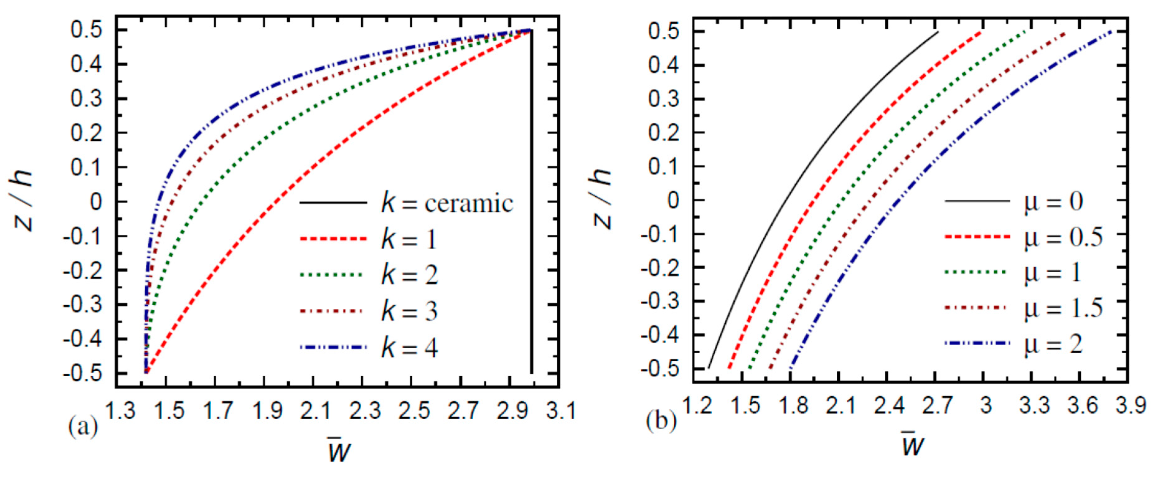
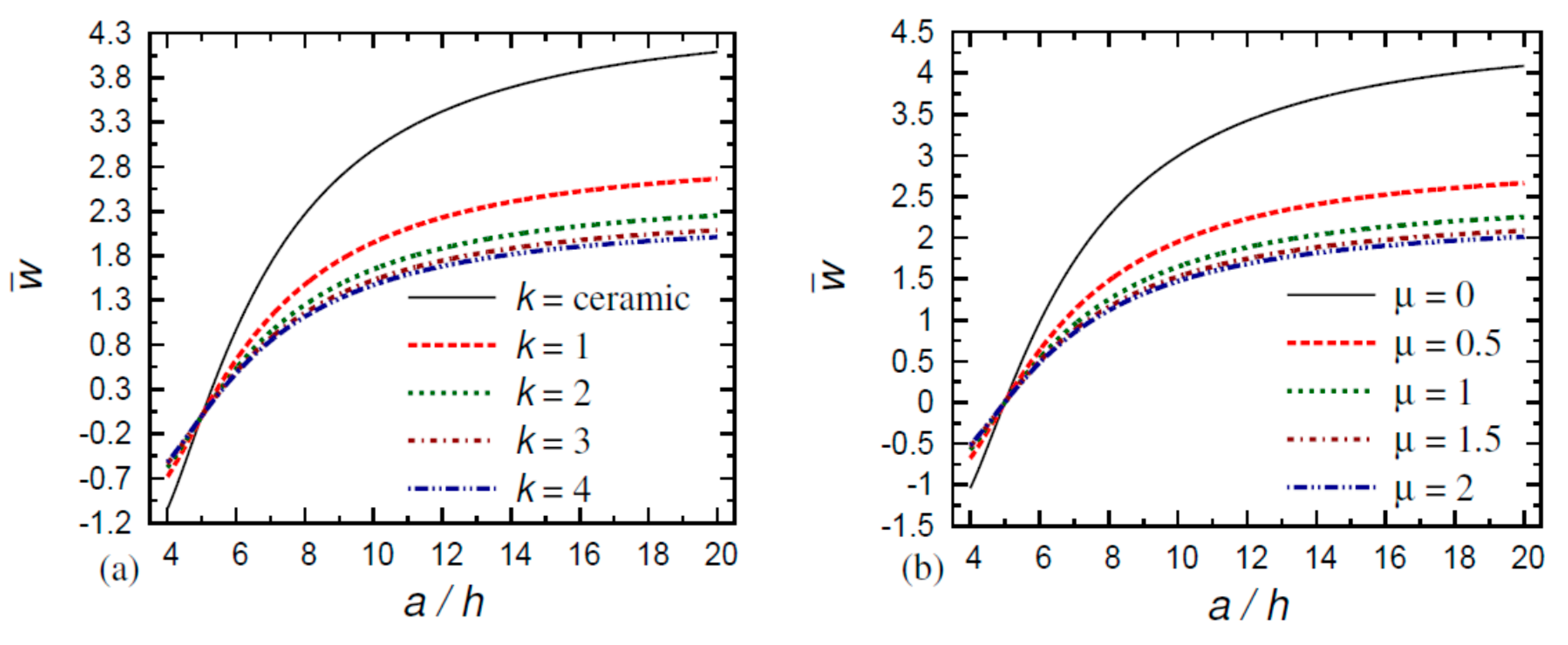
Figure 2 shows the variation in the non-dimensional displacements w ¯ of the FG square nanoplate through the thickness, a = 10 h (a) for different values of k ( μ = 0.5 ) and (b) for different values of μ ( k = 1 ). One can note that the deflection increases as the power law index k increases for the FG nano-plate (see Figure 2a), while it decreases as the nonlocal parameter μ increases (see Figure 2b). Figure 3 shows the variation in the non-dimensional displacements w ¯ of the FG square nanoplate versus the thickness ratio a / h , z / h = 0 (a) for different values of k ( μ = 0.5 ) and (b) for different values of μ ( k = 1 ). One can observe that the deflection increases as the power law index k and the nonlocal parameter μ increase; by increasing the side-to-thickness ratio, a / h increases.
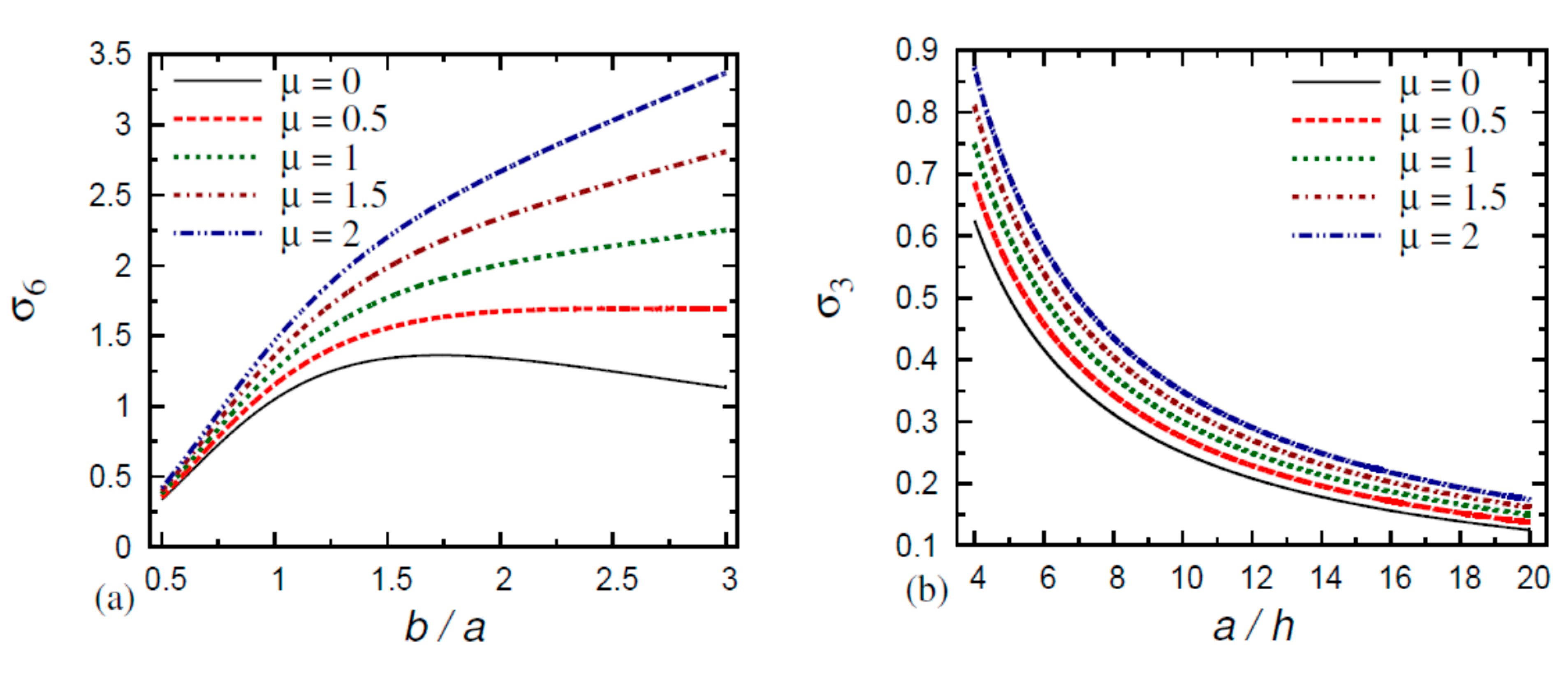
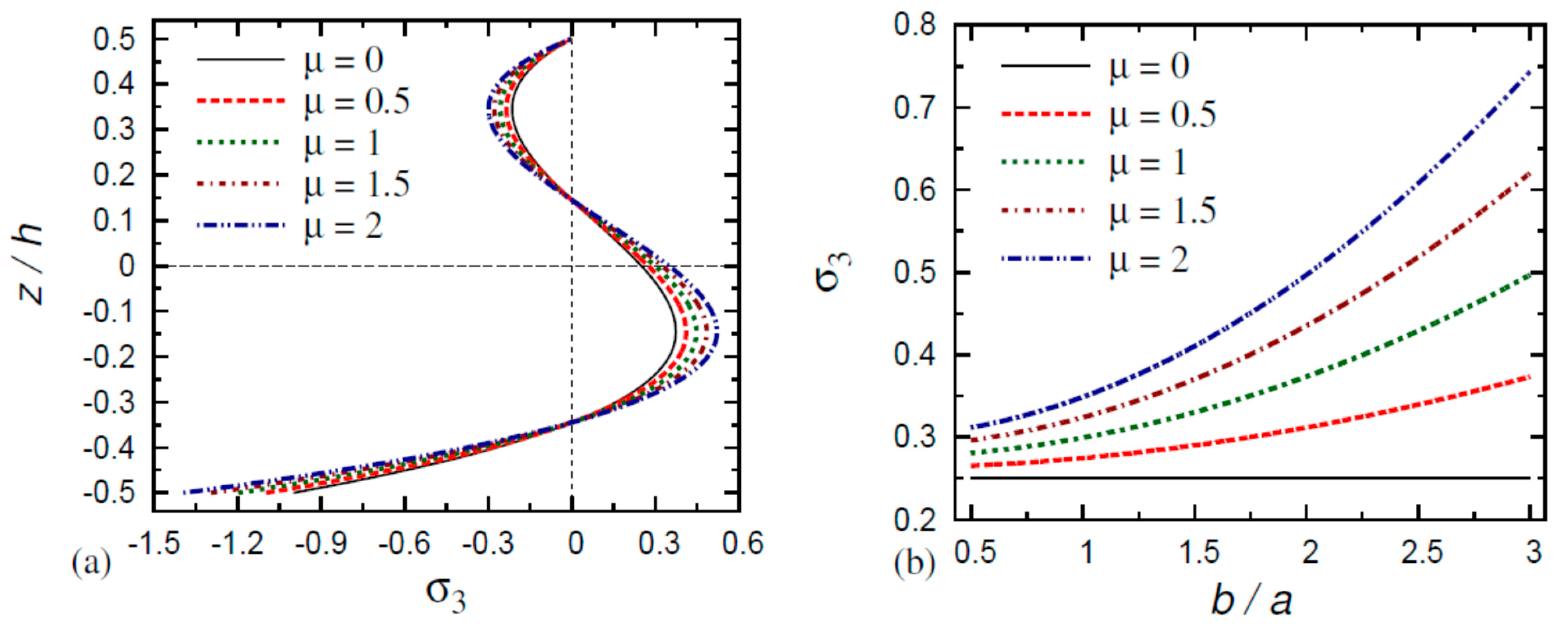
Figure 4 illustrates the variation in the non-dimensional deflection w ¯ of the FG nanoplate, z / h = 0 , a = 10 h (a) versus the aspect ratio b / a ( k = 1 ) and (b) for the small length scale μ ( a = b ). In Figure 4a, the deflection w ¯ increases as the aspect ratio b / a increases and with the increase in the nonlocal parameter μ . Furthermore, the deflection w ¯ is decreasing as k increases for the FG square nano-plate, as shown in Figure 4b. In addition, the value of w ¯ for the ceramic plate is the highest value. Figure 5 illustrates the variation in the non-dimensional stresses of the FG nanoplate (a) σ 6 versus the aspect ratio b / a ( a = 10 h ) and (b) σ 3 versus the thickness ratio a / h ( z / h = 0 , k = 1 ). It can be noted that the stress σ 6 increases by increasing the small-scale parameter μ . Additionally, the out-of-plane transverse normal stresses σ 3 is obviously decreasing by increasing the side-to-thickness ratio as a / h increases. Figure 6 shows the variation in the non-dimensional normal stress σ 3 of the FG square nanoplate (a) through the thickness distributions z / h and (b) versus the aspect ratio b / a ( a = 10 h , z / h = 0 ). The transverse normal stress σ 3 vanishes at the upper surface ( z / h = 0.5 ) and at the two positions z / h = 0.15 and z / h = 0.35 , respectively. In this respect, σ 3 increases as μ increases in the region 0.35 z / h 0.15 only, but it decreases as the small-scale parameter increases in the two intervals 0.5 z / h 0.35 and 0.15 z / h 0.5 . In Figure 6b, the transverse normal stress σ 3 increases with the increase in the aspect ratio b / a and the small-scale parameter μ . Furthermore, it is linearly constant when μ = 0 .
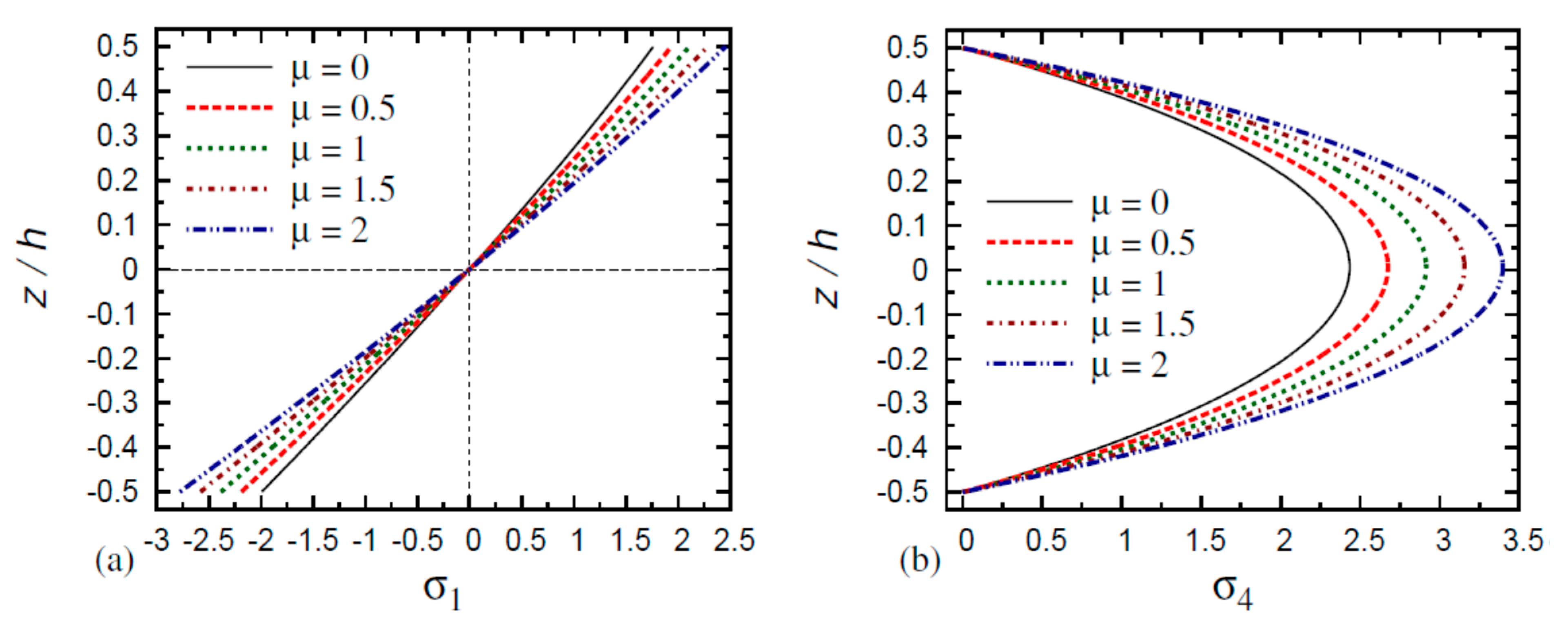
The variations in the normal stress σ 1 and transverse shear stress σ 4 through the thickness of the FG nanoplate are illustrated in Figure 7. In Figure 7a, the normal stress is tensile in the upper half-plane and compressive in the lower half-plane of the FG nanoplate. The normal stress increases with the increase in the small-scale parameter in the upper half-plane, while it is decreases in the lower half-plane of the FG nanoplate. From Figure 7b, the transverse shear stress increases as the small-scale parameter μ increases. The maximum value of transverse shear stress σ 4 arises at the mid-plane and this is irrespective of the values of the small-scale parameter.
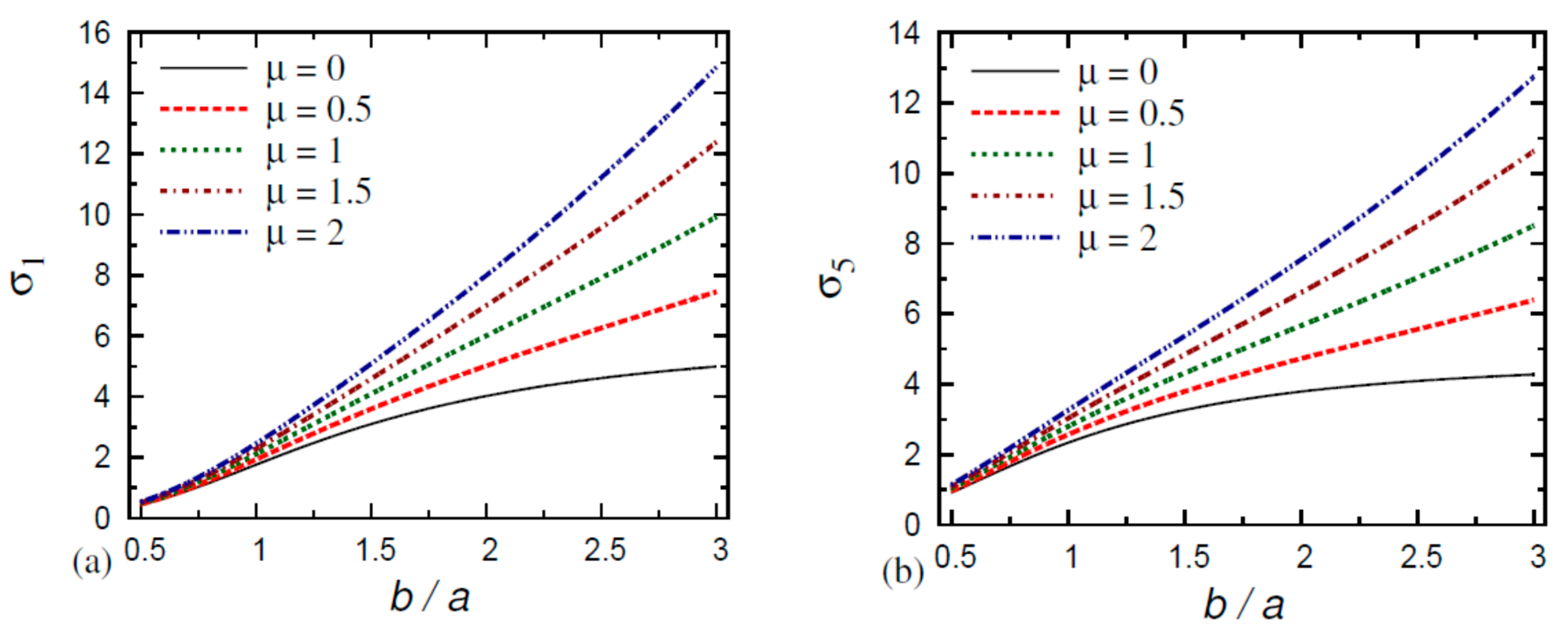
Finally, Figure 8 shows the variation in the normal stress σ 1 and transverse shear stress σ 5 versus the aspect ratio b / a of the FG nanoplate. It can be observed from both parts of this figure that the normal stress σ 1 is increases more as b / a increases, and it increases by increasing the small-scale parameter μ . The transverse shear stress σ 5 increases as b / a increases.

7. Conclusions

According to the mixed variational formula, the bending analysis is introduced for the FG nano-scale plate. To achieve the equilibrium equations, the virtual work principle is applied. Then, the solution of the equilibrium equations of the plate is achieved through the application of double Fourier series. The mechanical load is applied on the upper surface of the studied FG plate. The plate is under simply supported edge conditions. The effects of gradient index, side-to-thickness ratio, nonlocal parameter, and aspect ratio are demonstrated. Validation of the current theory is developed through comparison with published results. This study predicts the capacity to generate exact results in comparison with other theories. Thus, it is important to pay special attention to the application of numerical techniques.
The current study indicates that
  • The displacement difference of the FG nanoplate increases as the small-scale parameter increases and the gradient index decreases;
  • The displacement difference of the purely ceramic and purely metal nanoplates decreases as the thickness ratio increases;
  • The normal stress σ 1 in the FG nanoplate decreases as the thickness and aspect ratios increase and as the gradient index and small-scale parameter decrease;
  • The normal stress σ 2 in the FG nanoplate increases as the thickness ratio, aspect ratio, gradient index, and small-scale parameter decrease;
  • The transverse shear stresses σ 5 and σ 6 in the FG nanoplate increase as the thickness ratio, aspect ratio, gradient index, and small-scale parameter decrease.

Author Contributions

Conceptualization, A.M.Z.; methodology, A.M.Z., Z.S.H. and A.F.R.; validation, A.F.R.; formal analysis, Z.S.H.; writing—original draft preparation, A.M.Z., Z.S.H. and A.F.R.; writing—review and editing, A.M.Z., Z.S.H. and A.F.R.; visualization, Z.S.H. The manuscript was written through the contribution of all authors. All authors have read and agreed to the published version of the manuscript.

Funding

This research received no external funding.

Conflicts of Interest

The authors declare no conflict of interest.

References

  1. Lebaschi, A.H.; Deng, X.H.; Camp, C.L.; Zong, J.; Cong, G.T.; Carballo, C.B.; Album, Z.; Radeo, S. Biomechanical, histologic, and molecular evaluation of tendon healing in a new murine model of rotator cuff repair. Arthrosc. J. Arthrosc. Relat. Surg. 2018, 34, 1173–1183. [Google Scholar] [CrossRef]
  2. Johnson, K.L.; Gidley, M.J.; Bacic, A.; Doblin, M.S. Cell wall biomechanics: A tractable challenge in manipulating plant cell walls ‘fit for purpose’. Curr. Opin. Biotechnol. 2018, 49, 163–171. [Google Scholar] [CrossRef] [PubMed]
  3. Jandaghian, A.A.; Rahmani, O. Size-dependent free vibration analysis of functionally graded piezoelectric plate subjected to thermo-electromechanical loading. J. Intell. Mater. Syst. Struct. 2017, 28, 3039–3053. [Google Scholar] [CrossRef]
  4. Şimşek, M. Nonlinear free vibration of a functionally graded nanobeam using nonlocal strain gradient theory and a novel Hamiltonian approach. Int. J. Eng. Sci. 2016, 105, 12–27. [Google Scholar] [CrossRef]
  5. Eringen, A.C. On differential equations of nonlocal elasticity and solutions of screw dislocation and surface waves. J. Appl. Phys. 1983, 54, 4703–4710. [Google Scholar] [CrossRef]
  6. Peddieson, J.; Buchanan, G.R.; McNitt, R.P. Application of nonlocal continuum models to nanotechnology. Int. J. Eng. Sci. 2003, 41, 305–312. [Google Scholar] [CrossRef]
  7. Romano, G.; Barretta, R.; Diaco, M.; de Sciarra, F.M. Constitutive boundary conditions and paradoxes in nonlocal elastic nanobeams. Int. J. Mech. Sci. 2017, 121, 151–156. [Google Scholar] [CrossRef]
  8. Barretta, R.; Čanadija, M.; Feo, L.; Luciano, R.; de Sciarra, F.M.; Penna, R. Exact solutions of inflected functionally graded nano-beams in integral elasticity. Compos. B Eng. 2018, 142, 273–286. [Google Scholar] [CrossRef]
  9. Barretta, R.; Diaco, M.; Feo, L.; Luciano, R.; de Sciarra, F.M.; Penna, R. Stress-driven integral elastic theory for torsion of nano-beams. Mech. Res. Commun. 2018, 87, 35–41. [Google Scholar] [CrossRef]
  10. Barretta, R.; Canadija, M.; Luciano, R.; de Sciarra, F.M. Stress-driven modeling of nonlocal thermoelastic behavior of nanobeams. Int. J. Eng. Sci. 2018, 126, 53–67. [Google Scholar] [CrossRef] [Green Version]
  11. Zhang, D.G.; Zhou, Y.H. A theoretical analysis of FGM thin plates based on physical neutral surface. Comput. Mater. Sci. 2008, 44, 716–720. [Google Scholar] [CrossRef]
  12. Woo, J.; Meguid, S.A.; Ong, L.S. Nonlinear free vibration behavior of functionally graded plates. J. Sound Vib. 2006, 289, 595–611. [Google Scholar] [CrossRef]
  13. Yang, J.; Shen, H.S. Dynamic response of initially stressed functionally graded rectangular thin plates. Compos. Struct. 2001, 54, 497–508. [Google Scholar] [CrossRef]
  14. Hebali, H.; Tounsi, A.; Houari, M.S.A.; Bessaim, A.; Bedia, E.A.A. New quasi-3D hyperbolic shear deformation theory for the static and free vibration analysis of functionally graded plates. J. Eng. Mech. 2014, 140, 374–383. [Google Scholar] [CrossRef]
  15. Mahi, A.; Adda Bedia, E.A.; Tounsi, A. A new hyperbolic shear deformation theory for bending and free vibration analysis of isotropic, functionally graded, sandwich and laminated composite plates. Appl. Math. Model. 2015, 39, 2489–2508. [Google Scholar] [CrossRef]
  16. He, J.; Lilley, C.M. Surface effect on the elastic behavior of static bending nanowires. Nano Lett. 2008, 8, 1798–1802. [Google Scholar] [CrossRef]
  17. Asghari, M.; Rahaeifard, M.; Kahrobaiyan, M.; Ahmadian, M. The modified couple stress functionally graded Timoshenko beam formulation. Mater. Des. 2011, 32, 1435–1443. [Google Scholar] [CrossRef]
  18. Ansari, R.; Gholami, R.; Sahmani, S. Free vibration analysis of size-dependent functionally graded microbeams based on the strain gradient Timoshenko beam theory. Compos. Struct. 2011, 94, 221–228. [Google Scholar] [CrossRef]
  19. Rahmani, O.; Pedram, O. Analysis and modeling the size effect on vibration of functionally graded nanobeams based on nonlocal Timoshenko beam theory. Int. J. Eng. Sci. 2014, 77, 55–70. [Google Scholar] [CrossRef]
  20. Eringen, A.C. Nonlocal Continuum Field Theories; Springer: Berlin/Heidelberg, Germany, 2002. [Google Scholar]
  21. Eringen, A.C.; Edelen, D. On nonlocal elasticity. Int. J. Eng. Sci. 1972, 10, 233–248. [Google Scholar] [CrossRef]
  22. Thai, H.T. A nonlocal beam theory for bending, buckling, and vibration of nanobeams. Int. J. Eng. Sci. 2012, 52, 56–64. [Google Scholar] [CrossRef]
  23. Zenkour, A.M.; Sobhy, M. A simplified shear and normal deformations nonlocal theory for bending of nanobeams in thermal environment. Phys. E 2015, 70, 121–128. [Google Scholar] [CrossRef]
  24. Zenkour, A.M. Torsional dynamic response of a carbon nanotube embedded in visco-Pasternak’s medium. Math. Model. Anal. 2016, 21, 852–868. [Google Scholar] [CrossRef]
  25. Arefi, M.; Zenkour, A.M. Thermo-electro-mechanical bending behavior of sandwich nanoplate integrated with piezoelectric face-sheets based on trigonometric plate theory. Compos. Struct. 2017, 162, 108–122. [Google Scholar] [CrossRef]
  26. Zenkour, A.M. Nonlocal thermoelasticity theory without energy dissipation for nano-machined beam resonators subjected to various boundary conditions. Microsyst. Technol. 2017, 23, 55–65. [Google Scholar] [CrossRef]
  27. Arefi, M.; Zenkour, A.M. Wave propagation analysis of a functionally graded magneto-electro-elastic nanobeam rest on visco-Pasternak foundation. Mech. Res. Commun. 2017, 79, 51–62. [Google Scholar] [CrossRef]
  28. Zenkour, A.M.; Aljadani, M.H. Thermo-electrical buckling response of actuated functionally graded piezoelectric nanoscale plates. Res. Phys. 2019, 13, 102192. [Google Scholar] [CrossRef]
  29. Mashat, D.S.; Zenkour, A.M. Modified DPL Green–Naghdi theory for thermoelastic vibration of temperature-dependent nanobeams. Res. Phys. 2020, 16, 102845. [Google Scholar] [CrossRef]
  30. Ahouel, M.; Houari, M.S.A.; Bedia, E.A.; Tounsi, A. Size-dependent mechanical behavior of functionally graded trigonometric shear deformable nanobeams including neutral surface position concept. Steel Compos. Struct. 2016, 20, 963–981. [Google Scholar] [CrossRef]
  31. Zenkour, A.M. Buckling and free vibration of elastic plates using simple and mixed shear deformation theories. Acta Mech. 2001, 146, 183–197. [Google Scholar] [CrossRef]
  32. Zenkour, A.M. Natural vibration analysis of symmetrical cross-ply laminated elastic plates using mixed variational formulation. Eur. J. Mech. A/Solids 2000, 19, 469–485. [Google Scholar] [CrossRef]
  33. Zenkour, A.M. Stress analysis of axisymmetric shear deformable cross-ply circular laminated cylindrical shells. J. Eng. Math. 2001, 40, 315–332. [Google Scholar] [CrossRef]
  34. Zenkour, A.M. A simple four-unknown refined theory for bending analysis of functionally graded plates. Appl. Math. Model. 2013, 37, 9041–9051. [Google Scholar] [CrossRef]
  35. Zenkour, A.M. A novel mixed nonlocal elasticity theory for thermoelastic vibration of nanoplates. Compos. Struct. 2018, 185, 821–833. [Google Scholar] [CrossRef]
  36. Goli, E.; Bayesteh, H.; Mohammadi, S. Mixed mode fracture analysis of adiabatic cracks in homogeneous and non-homogeneous materials in the framework of partition of unity and the path-independent interaction integral. Eng. Fract. Mech. 2014, 131, 100–127. [Google Scholar] [CrossRef]
  37. Srinivas, S.; Rao, A.K. Bending, vibration and buckling of simply-supported thick orthotropic rectangular plates and laminates. Int. J. Solids Struct. 1970, 6, 1463–1481. [Google Scholar] [CrossRef]
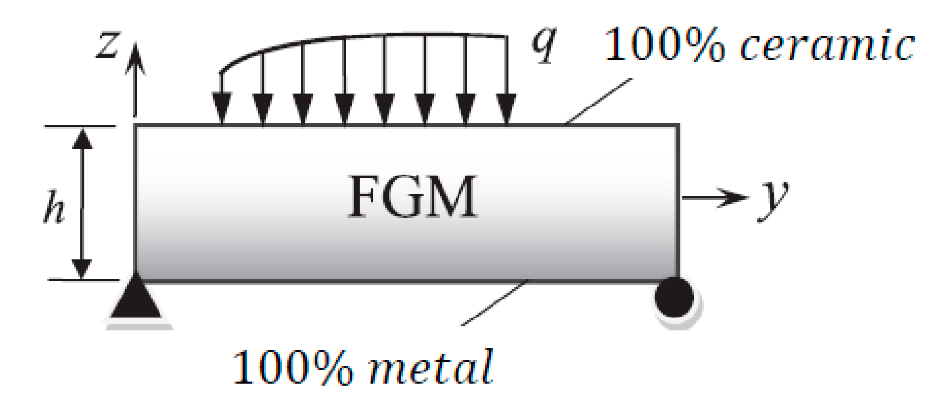
Figure 1. Geometry of the nanoplate made of functionally graded materials (FGM).
Mathematics 08 01162 g001
Figure 2. Variation in non-dimensional displacements w ¯ of FG square nanoplates through the thickness, a / h = 10 (a) for different values of k ( μ = 0.5 ) and (b) for different values of μ ( k = 1 ).
Mathematics 08 01162 g002
Figure 3. Variation in non-dimensional displacements w ¯ of FG square nanoplates versus the thickness ratio a / h , z / h = 0 (a) for different values of k ( μ = 0.5 ) and (b) for different values of μ ( k = 1 ).
Mathematics 08 01162 g003
Figure 4. Variation in non-dimensional displacements w ¯ of FG nanoplates, a / h = 10 , z / h = 0 (a) versus the aspect ratio b / a ( k = 1 ) and (b) versus the small length scale μ ( a = b ).
Mathematics 08 01162 g004
Figure 5. Variation in non-dimensional stresses of FG nanoplates (a) σ 6 versus the aspect ratio b / a ( a / h = 10 ) and (b) σ 3 versus the thickness ratio a / h ( a = b ) ( k = 1 , z / h = 0 ).
Mathematics 08 01162 g005
Figure 6. Variation in non-dimensional normal stress σ 3 of FG nanoplates (a) through the thickness ( a = b ) and (b) versus the aspect ratio b / a ( k = 1 , a / h = 10 ).
Mathematics 08 01162 g006
Figure 7. The through the thickness distributions of the stresses in FG square nanoplates for different values of small length scale μ . (a) The in-plane stress σ 1 and (b) the shear stress σ 4 ( k = 1 , a / h = 10 ).
Mathematics 08 01162 g007
Figure 8. Variation in non-dimensional stresses in FG nanoplates versus the aspect ratio b / a for different values of small length scale μ . (a) The in-plane stress σ 1 and (b) the shear stress σ 5   ( k = 1 , a / h = 10 ).
Mathematics 08 01162 g008
Table 1. Properties of the material alumina/nickel (Goli et al. [36]).
E 1 c ,   E 2 c ,   E 3 c ,   G 12 c ,   G 13 c ,   G 23 c (GPa) 90.43 ,   116.36 ,   90.43 ,   38.21 ,   38.21 ,   38.21
E 1 m ,   E 2 m ,   E 3 m ,   G 12 m ,   G 13 m ,   G 23 m (GPa) 204 ,   204 , 204 ,   77.9 ,   77.9 , 77.9
ν c 12 ,   ν c 13 ,   ν c 31 ,   ν c 32 0.22 ,   0.14 ,   0.14 ,   0.21  
ν m 12 ,   ν m 13 ,   ν m 31 ,   ν m 32 0.31 ,   0.31 ,   0.31 ,   0.31  
Table 2. Effects of thickness and aspect ratios for the orthotropic plate on deflection w ^ under uniform load (100 term series).
a b Theory h / b
0.140.100.05
2Ref. [37] (Exact)387.231408.521,542
Ref. [37] (CLPT)344.931325.121,201
Present388.141411.121,577
1Ref. [37] (Exact)191.07688.5710,443
Ref. [37] (CLPT)166.70640.3910,246
Present191.92690.6310,463
0.5Ref. [37] (Exact)39.790139.082048.7
Ref. [37] (CLPT)32.345124.261988.1
Present40.2749140.0212054.3
Table 3. The non-dimensional deflection w ¯ in a square FG nano-scale plate at a / h = 10 .
k μ
0 0.5 1 1.5 2 2.5 3
Ceramic2.72222.99093.25963.52823.79694.06564.3342
11.77611.95152.12682.30232.47742.65272.8280
21.50121.64941.79761.94582.09382.24202.3903
31.39061.52791.66511.80221.93952.07672.2142
41.34071.47311.60541.73761.87002.00212.1346
51.31721.44731.57731.70721.83731.96722.0972
Metal1.29231.41991.54741.67491.80251.93002.0576
Table 4. The non-dimensional in plane stresses in an FG nano-scale plate.
b / a a / h μ σ 1 σ 2  
k = 0 k = 2 k = 4 k = 8 k = 0 k = 1 k = 4 k = 8
11000.17600.17630.18330.17620.21460.21490.21480.2150
0.50.19340.19360.20030.19370.23580.23610.23580.2362
10.21080.21100.21760.21110.25690.25730.25720.2574
20.24550.24590.25170.24590.29930.29980.29920.2998
3000.17710.17690.17690.17690.21660.21650.21650.2162
10.19460.19440.19450.19350.23790.23780.23790.2373
20.21210.21190.21180.21110.25930.25920.25920.2593
40.24700.24680.24680.24660.30210.30190.30190.3016
21000.40210.40260.40270.40280.22690.22690.22720.2271
10.50130.50190.50200.50230.28280.28290.28320.2832
20.60060.60110.60130.60170.33880.33890.33930.3392
40.79900.79980.79990.80030.45080.45090.45140.4512
3000.40680.39750.39710.41430.22970.22550.22460.2191
10.50710.49210.49540.50810.28640.27800.27990.2744
20.60750.58840.59340.60680.34300.33870.33530.3298
40.80820.78410.79030.80890.45640.44920.44620.4375
Table 5. The non-dimensional transverse stresses in FG nano-scale plate.
a / b a / h μ σ 5 σ 6
k = 0 k = 1 k = 4 k = 8 k = 0 k = 1 k = 4 k = 8
11000.22330.23390.23840.23860.10850.10490.10490.1049
10.26740.28000.28550.28580.12990.12570.12570.1257
20.31150.32610.33260.33290.15140.14640.14640.1464
40.39970.41830.42680.42710.19420.18790.18790.1878
3000.22340.23540.24440.23530.10940.10560.10560.0973
10.26750.28150.29290.28120.13090.12640.12640.1202
20.31160.32740.34140.32700.15250.14730.14730.1429
40.39980.41950.43850.41860.19570.18890.18890.1886
21000.37390.37870.37960.38210.14860.13430.13430.1343
10.55840.56630.56730.57090.22190.20060.20060.2006
20.74290.75390.75480.75990.29530.26680.26690.2669
41.11191.12921.12991.13740.44200.39940.39950.3995
3000.38290.38800.41490.34060.15050.13310.13420.7146
10.57200.57540.62080.51060.22480.19870.19981.1152
20.76090.76270.82690.68130.29900.26440.26531.5142
41.13901.13751.23881.02190.44760.39580.39642.3117