Article

Engineering Applications of Peristaltic Fluid Flow with Hall Current, Thermal Deposition and Convective Conditions

1
Department of Basic Sciences, Preparatory Year Deanship, King Faisal University, Al-Ahsa 31982, Saudi Arabia
2
Department of Mathematics, College of Science, University of Ha’il, Ha’il 81481, Saudi Arabia
3
Department of Mathematics, Mirpur University of Science and Technology (MUST), Mirpur 10250, AK, Pakistan
*
Author to whom correspondence should be addressed.
Mathematics 2020, 8(10), 1710; https://doi.org/10.3390/math8101710
Submission received: 16 September 2020 / Revised: 24 September 2020 / Accepted: 26 September 2020 / Published: 4 October 2020
(This article belongs to the Special Issue Computational Mechanics in Engineering Mathematics)

Abstract

:
This article addresses the peristaltic flow in a compliant wall channel. Analysis has been carried out in the presence of a Hall current and chemical reaction. Convective conditions in terms of both heat and mass transfer are employed. Mathematical modeling is developed for an incompressible Carreau fluid. Thermal deposition effect and convection at the channel walls are considered. Series solutions are obtained for small Weissenberg number W e . Solution expressions of velocity, temperature, concentration and stream function are obtained. These physical quantities are displayed and analyzed. Heat transfer coefficient and trapping are explored in detail.

1. Introduction

In view of immense utility in a number of physiological and industrial applications such as ingesting food via the esophagus, chyme movement in the gastrointestinal tract, vasomotion of blood vessels such as veins, capillaries and vertebral arteries, transport of urine from the kidney to the bladder, transport of hygienic fluids, transfer of corrosive fluids, transport of toxic fluids in the nuclear power industry, etc., peristalsis has acquired a great deal of attention among recent researchers. Several experimental and theoretical efforts have been made on peristalsis since the pioneering work of Latham [1] and Shapiro et al. [2]. In study [2], assumptions of long wavelength and low Reynolds number are used. However, in chemical and biomedical systems, fluids are of a non-Newtonian type in nature. There is not a single model which can describe the rheological characteristics of all the non-Newtonian fluids. Therefore, many models of non-Newtonian fluids are proposed [3,4,5,6,7,8,9,10,11]. The Carreau fluid model (or modified power-law model) specifies rheological behavior of fluid and is thus characterized as non-Newtonian fluid. The Carreau model [12,13] is comprised of four additional parameters in comparison to viscous fluid model describing the useful properties of a truncated power law model that does not correspond discontinuous first derivative. In addition, this fluid model possesses shear thinning and zero shear rate effects (governed by η and η 0 , respectively) and the power law index ( n ) accounts for the degree of non-Newtonian behavior.
The fluid flows with heat as well as mass transfer using peristalsis are utilized in the biomedical sciences for instance, bio-heat exchange processes such as skin burn, metabolic heat production, blood flow perfusion, thermoregulation, evaporation, hypothermia, convection and fever in the living body systems. In addition, the processes of bio-mass transfer employ blood as a carrier of oxygen, transfer of oxygen in a tissue, drug transfer inside body, ionic and diffusive flows through membrane channels, etc. Several recent research works on this subject have been published in Refs. [14,15,16]. The transfer of heat from one place to another by actual movement of fluids is termed as convective heat transfer (often referred to as convection). The convective transfer of heat and mass is major mode of naturally occurring processes like movement of fluid within the earth’s mantle, oceanic currents and wind. The convective boundary conditions is a more general approach mostly employed to define a linear convective heat exchange condition for one or more algebraic entities in thermal energy storage, gas turbines, nuclear plants, etc. The flows with heat transfer convective boundary conditions are recently examined by Waqas et al. [17]. There are also few investigations describing the effect of convective conditions in peristalsis (see [18,19,20,21,22]). Furthermore, convection is much more important when thermophoretic migration of fluid particle suspensions is predicted. Practical importance in many industries includes gas filtration and nuclear reactor safety. The design of many particle-laden systems demands an approximation of the rate of thermal deposition because it depends on the temperature gradient at a macroscopic level and also on the thermophoretic coefficient evaluation. The thermophoretic phenomenon is significant in aerosol mixtures and to manufacture graded index germanium dioxide and silicon dioxide used in the field of communications (see Refs. [23,24]). Further MHD flows with heat transfer have an immense utility in different fields because it is relevant to many geophysical and astrophysical processes, cooling of continuous strips, the metallurgy industry and filaments drawn through a quiescent fluid. Its medical utility involves identification of tumors in the brain using Magnetic Resonance Imaging (MRI) [25,26,27,28]. Furthermore, magnetohydrodynamics (MHD) flows with peristalsis is important in connection with certain problems of the movement of the conductive physiological fluids, e.g., the blood and blood pump machines. Few recent attempts testifying such flows are mentioned in Refs. [29,30,31,32]. Furthermore, the influence of the Hall current can not be overlooked while a significant magnetic field is assumed to be applied. In particular, the study of MHD flows with a Hall current has important engineering applications for magnetohydrodynamic generators and Hall accelerators, cardiac MRI, ECG, etc. Recent studies characterizing Hall effect can be seen through the investigations [33,34,35,36].
The purpose of present study is to venture further into the regime of peristaltic flows of non-Newtonian fluids in a compliant wall channel. The main theme of present article is threefold—firstly to examine the peristaltic flow through heat and mass convective conditions; secondly to analyze the effect of Hall current; and thirdly to investigate the chemical reaction effects in the presence of thermal deposition. The relevant problems formulation is first made and then solved using the perturbation method. Long wavelength and low Reynolds number assumptions are utilized. Flow quantities of interest are analyzed in detail via graphs.

2. Formulation of Problem

We consider the two-dimensional peristaltic flow of an incompressible Carreau fluid with thermal deposition and Hall current. The channel walls of width 2 d satisfy the compliant properties. Peristaltic flow is generated by a sinusoidal wave traveling with speed c along the channel walls (see Figure 1). Convective heat and mass conditions with chemical reaction are employed in the analysis. The configuration of the wall surface is assessed by:
y = ± η ( x , t ) = d + a sin 2 π λ ( x c t ) ,
where the wavelength is represented by λ , a is the wave amplitude, t the time, 2 d is the width of the channel which is symmetric, and + η displacement of the upper wall whereas displacement of the lower wall is denoted by η .
We implement the uniform magnetic field as in the form
B 0 = ( 0 , 0 , B 0 ) .
The Ohm’s law is stated as
J = σ E .
The generalized Ohm’s law [34,35,36] for the consideration of Hall effects can be written as follows:
J = σ [ E + V × B 0 1 e n ˘ ( J × B 0 ) ] ,
where V is the fluid velocity vector, J is the current density, σ the electrical conductivity, n ˘ the number density of electrons and e the electric charge. Here, we neglected the influence of the electric force i.e., E = 0 .
If V = [ u , v , 0 ] is the fluid velocity vector with u a n d v, the velocity components along x- and y-directions, respectively. From Equations (2) and (3), we obtain
J × B 0 = σ B 0 2 1 + m 2 u m v , v + m u , 0 ,
where m = σ B 0 e n ˘ represents the Hall current parameter.
The appropriate equations for the current flow study are the following:
u x + v y = 0 ,
ρ d u d t = p x + R x x x + R x y y σ B 0 2 1 + m 2 u m v ,
ρ d v d t = p y + R y x x + R y y y σ B 0 2 1 + m 2 v + m u ,
ρ c p d T d t = k 2 T x 2 + 2 T y 2 ,
d C d t = D 2 C x 2 + 2 C y 2 x + y V T ( C C 0 ) k 1 C C 0 ,
where the velocity corresponding to thermal deposition V T can be defined as follows:
V T = k * ν T T r = k * ν T r x + y T ,
in which T r denotes the reference temperature and k * represents the coefficient of thermophoresis. In addition, for Carreau fluid, the extra stress tensor R can be written as
R = [ η + ( η 0 η ) ( 1 + ( Γ γ ˙ ) 2 ) n 1 2 ) ] γ ˙ ,
where η 0 and η represent the zero and the infinite shear rate viscosities, respectively, n is the dimensionless form of power law index ( n < 1 ) , and Γ is the time constant. In addition, γ ˙ is expressed as:
γ ˙ = 1 2 i j γ ˙ i j γ ˙ j i = 1 2 Π ,
where the second invariant strain tensor Π is defined by Π = t r [ V + ( V ) t ] 2 and γ ˙ = V + ( V ) t . Here, we consider the case when η = 0 and also Γ γ ˙ < 1 . Therefore, Equation (11) takes the form
R = η 0 ( 1 + ( Γ γ ˙ ) 2 n 1 2 ) γ ˙ .
It is worth mentioning that the above model reduces to the viscous/Newtonian model for Γ = 0 or n = 1 . The components of extra stress tensor are provided by
R x x = 2 μ 0 [ 1 + n 1 2 ( Γ γ ˙ ) 2 ] u x ,
R x y = μ 0 [ 1 + n 1 2 ( Γ γ ˙ ) 2 ] ( u y + v x ) = R y x ,
R y y = 2 μ 0 [ 1 + n 1 2 ( Γ γ ˙ ) 2 ] v y ,
in which ρ is the density of fluid, ν the kinematic viscosity, d d t material time derivative, μ 0 the dynamic fluid viscosity, C the concentration of fluid, T the fluid temperature, T 1 , T 0 are the temperatures and C 1 , C 0 the concentrations at the upper and lower channel walls, respectively, the coefficient of mass diffusivity is D, the specific heat c p of fluid, k 1 the coefficient of chemical reaction parameter, the thermal conductivity k, c s the susceptibility of concentration, K T the diffusion ratio of temperature and V T the velocity of thermophoresis.
The distribution of convective heat and convective mass at the walls is determined by
k T y = h 1 ( T T 1 ) , at y = + η , k T y = h 2 ( T 0 T ) , at y = η , D C y = h 3 ( C C 1 ) , at y = + η ,
D C y = h 4 ( C 0 C ) , at y = η .
Here, h 1 and h 2 signify the coefficients of heat transfer at upper and lower channel walls and h 3 and h 4 show the coefficients of mass transfer at the upper wall and lower wall of channels, respectively.
At the boundary wall, the conditions for no-slip are expressed as follows:
u = 0 , v = ± η t at y = ± η .
The following statements are defined as being compatible with the compliant nature of the walls:
τ 3 x 3 + m 1 * 3 x t 2 + d 2 t x η = ρ d u d t + R x x x + R x y y σ B 0 2 1 + m 2 u m v a t y = ± η ,
where, in the membrane, the elastic tension is denoted by τ , the mass per unit area is symbolized as m 1 * and d is the coefficient of viscous damping.
Performing y ( 6 ) x ( 7 ) , we get
ρ d d t u y v x = 2 R x y y 2 2 R y x x 2 + 2 R x x y x 2 R y y x y σ B 0 2 1 + m 2 u y m v y + σ B 0 2 1 + m 2 v x + m u x .
Incorporating the stream function ψ x , y , t and specifying the aforementioned non-dimensional variables:
u = ψ y , v = ψ x ,
ψ * = ψ c d , x * = x λ , y * = y d , t * = c t λ , η * = η d , γ = k 1 d 2 υ , θ = T T 0 T 1 T 0 , γ ˙ ^ = d c γ ˙ , ϕ = C C 0 C 1 C 0 , R x x * = λ μ 0 c R x x , R x y * = d μ 0 c R x y , R y x * = d μ 0 c R y x , R y y * = d μ 0 c R y y .
Equations ( 8 ) , ( 9 ) and ( 21 ) yield
δ Re d d t 2 ψ y 2 + δ 2 2 ψ x 2 = δ 2 2 R x x y x δ 2 2 R y x x 2 + 2 R x y y 2 + δ 2 R y y x y m 1 2 1 + m 2 2 ψ y 2 + δ 2 2 ψ x 2 ,
δ Pr Re d θ d t = δ 2 2 θ x 2 + 2 θ y 2 , δ Re d ϕ d t = 1 S c δ 2 2 ϕ x 2 + 2 ϕ y 2 τ * ϕ 2 θ y 2 + δ 2 2 θ x 2 + 2 δ 2 θ y x
τ * θ y + δ θ x ϕ y + δ ϕ x γ ϕ ,
with the conditions
η = 1 + ϵ sin 2 π x t ,
θ y + γ h 1 ( θ 1 ) = 0 at y = + η , θ y γ h 2 θ = 0 at y = η ,
ϕ y + γ m 1 ( ϕ 1 ) = 0 at y = + η ,
ϕ y γ m 2 ϕ = 0 at y = η ,
ψ y = 0 at y = ± η ,
1 3 x 3 + E 2 3 x t 2 + E 3 2 x t ] η = Re δ d d t ( ψ y ) + δ 2 x R x x + y R x y m 1 2 1 + m 2 ψ y + m δ ψ x at y = ± η .
In addition, Equations (14)–(16) become
R x x = 2 ( 1 + n 1 2 W e 2 γ ˙ ^ 2 ) ψ x y ,
R x y = R y x = 2 ( 1 + n 1 2 W e 2 γ ˙ ^ 2 ) ( ψ y y δ 2 ψ x x ) ,
R y y = 2 δ ( 1 + n 1 2 W e 2 γ ˙ ^ 2 ) ψ x y .
For convenience, asterisks have been removed in the described equations. Here, Re, S c , δ , Pr and m 1 are the Reynolds, Schmidt numbers, the dimensionless wave number, Prandtl and Hartman numbers, ϵ is the amplitude ratio and the non-dimensional elasticity parameters E 1 , E 2 , E 3 ; moreover, γ is a chemical-reaction parameter, the thermophoretic parameter τ * , the heat/mass transfer Biot numbers γ h 1 , γ h 2 and γ m 1 , γ m 2 , respectively, the Weissenberg number W e , and γ ˙ ^ (dimensional form is γ ˙ ) are expressed by:
δ = d λ , Re = c d ν , Pr = μ c p k , ϵ = a d , γ = k 1 d 2 ν , W e = Γ c d , E 1 = τ d 3 λ 3 μ 0 c , E 2 = m 1 * c d 3 λ 3 μ 0 , E 3 = d 3 d μ λ 2 , S c = μ 0 ρ D ,
γ ˙ ^ = 4 δ 2 2 ψ x y 2 + 2 ψ y 2 δ 2 2 ψ x 2 ,
γ m 1 = h 3 d D , γ m 2 = h 4 d D , γ h 1 = h 1 d k , γ h 2 = h 2 d k ,
m 1 2 = σ B 0 2 d 2 μ 0 , τ * = k * ( T 1 T 0 ) T r .
Through long wavelength and low Reynolds number approximations, we obtain the following set of equations:
4 ψ y 4 + 3 2 ( n 1 ) W e 2 4 ψ y 4 2 ψ y 2 2 + 3 ( n 1 ) W e 2 3 ψ y 3 2 2 ψ y 2 m 1 2 1 + m 2 2 ψ y 2 = 0 ,
2 θ y 2 = 0 ,
1 S c 2 ϕ y 2 τ * ϕ 2 θ y 2 τ * θ y ϕ y γ ϕ = 0 ,
ψ y = 0 at y = ± η ,
θ y + γ h 1 θ 1 = 0 , at y = + η , θ y γ h 2 θ = 0 , at y = η ,
ϕ y + γ m 1 ϕ 1 = 0 , at y = + η ,
ϕ y γ m 2 ϕ = 0 , at y = η ,
[ E 1 3 x 3 + E 2 3 x t 2 + E 3 2 x t ] η = 3 ψ y 3 + 3 2 ( n 1 ) W e 2 2 ψ y 2 2 3 ψ y 3 m 1 2 1 + m 2 ψ y at y = ± η .

2.1. Method of Solution

In view of nonlinearity of the resulting system, the perturbation method is employed to obtain a series solutions of stream function ψ , temperature θ , concentration ϕ and heat transfer coefficient Z. According to the regular perturbation method, these flow quantities can be represented as the convergent Taylor series for the small parameter Weissenberg number W e . In order to do so, we describe the flow quantities to the forms:
ψ = ψ 0 + W e 2 ψ 1 + O W e 4 , θ = θ 0 + W e 2 θ 1 + O W e 4 , ϕ = ϕ 0 + W e 2 ϕ 1 + O W e 4 , Z = Z 0 + W e 2 Z 1 + O ( W e 4 ) .

2.2. System of Order We 0 with Solution

The zeroth order system is specified by
4 ψ 0 y 4 m 1 2 1 + m 2 2 ψ 0 y 2 = 0 ,
2 θ 0 y 2 = 0 ,
1 S c 2 ϕ 0 y 2 τ * ϕ 0 2 θ 0 y 2 τ * θ 0 y ϕ 0 y γ ϕ 0 = 0 ,
ψ 0 y = 0 , at y = ± η ,
θ 0 y + γ h 1 ( θ 0 1 ) = 0 at y = + η , θ 0 y γ h 2 θ 0 = 0 at y = η ,
ϕ 0 y + γ m 1 ( ϕ 0 1 ) = 0 at y = + η , ϕ 0 y γ m 2 ϕ 0 = 0 at y = η ,
[ E 1 3 x 3 + E 2 3 x t 2 + E 3 2 x t ] η = 3 ψ 0 y 3 m 1 2 1 + m 2 ψ 0 y at y = ± η .
The solutions to Equations (47)–(49) subjected to the relevant boundary constraints (50)–(53) are
ψ 0 = A 2 H y sech ( H η ) sinh ( H y ) ,
θ 0 = γ h 1 1 + ( y + η ) γ h 2 B 2 ,
ϕ 0 = γ m 1 B 4 × [ B 1 + B 3 2 B 2 γ m 2 exp ( B 3 B 1 ) ( y η ) 2 B 2 + B 1 B 3 + 2 B 2 γ m 2 exp B 3 ( y η ) + B 1 ( y + 3 η ) 2 B 2 ] ,
Z 0 = η x θ 0 y ( η ) , = η x γ h 1 γ h 2 B 2 .

2.3. System of Order We 2 with Solution

At this order, we have
4 ψ 1 y 4 + 3 2 ( n 1 ) 4 ψ 0 y 4 2 ψ 0 y 2 2 + 3 ( n 1 ) 3 ψ 0 y 3 2 2 ψ 0 y 2 m 1 2 1 + m 2 2 ψ 1 y 2 = 0 ,
2 θ 1 y 2 = 0 ,
1 S c 2 ϕ 1 y 2 τ * ϕ 0 2 θ 1 y 2 τ * ϕ 1 2 θ 0 y 2 τ * θ 0 y ϕ 1 y τ * θ 1 y ϕ 0 y γ ϕ 1 = 0 ,
ψ 1 y = 0 , at y = ± η ,
θ 1 y + γ h 1 θ 1 = 0 at y = + η , θ 1 y γ h 2 θ 1 = 0 at y = η ,
ϕ 1 y + γ m 1 ϕ 1 = 0 at y = + η , ϕ 1 y γ m 2 θ 1 = 0 at y = η ,
3 ψ 1 y 3 + 3 2 ( n 1 ) 3 ψ 0 y 3 2 ψ 0 y 2 2 m 1 2 1 + m 2 ψ 1 y = 0 at y = ± η .
Solving Equations (59)–(61) and imposing the relevant boundary conditions, one can get the solutions in the following form:
ψ 1 = A 3 A 4 exp H ( 3 y + 2 η ) × [ 3 exp 2 H y + 3 exp 4 H y + exp 2 H η + exp 4 H η exp 2 H ( 3 y + η ) exp 2 H ( 3 y + 2 η ) 3 exp 2 H ( y + 3 η ) + 3 exp 2 H ( 2 y + 3 η ) + 12 ( H ( y η ) 1 ) exp 4 H ( y + η ) + 12 ( H ( y η ) + 1 ) exp 2 H ( y + η ) + 12 ( H ( y + η ) 1 ) exp 2 H ( 2 y + η ) + 12 ( H ( y + η ) + 1 ) exp 2 H ( y + 2 η ) ] ,
θ 1 = 0 ,
ϕ 1 = 0 ,
and the heat transfer coefficient is
Z 1 = η x θ 1 y ( η ) = 0 ,
in which
H = m 1 2 1 + m 2 , A 1 = 2 ( E 1 + E 2 ) π cos 2 π ( t x ) + E 3 sin 2 π ( t x ) , A 2 = 4 π 2 ϵ A 1 H 3 / 2 , A 3 = ( n 1 ) π 6 ϵ 3 2 1 + exp 2 H η H 5 / 2 , A 4 = A 1 3 sech 3 ( H η ) , B 1 = B 3 2 + 4 γ S c B 2 2 , B 2 = γ h 1 + γ h 2 + 2 η γ h 1 γ h 2 , B 3 = S c τ γ h 1 γ h 2 , B 4 = 2 γ h 2 ( S c γ + γ m 1 γ m 2 ) 1 + exp 2 B 1 η B 2 + B 1 ( γ m 1 + γ m 2 ) 1 + exp 2 B 1 η B 2 + γ h 1 2 γ m 1 γ m 2 + 2 S c γ + γ h 2 4 S c γ η + S c τ γ m 2 + γ m 1 4 γ m 2 η S c τ 1 + exp 2 B 1 η B 2 .

3. Results and Analysis

This section determines the variation of the fluid velocity, heat transfer coefficient, temperature, fluid concentration and pattern of streamlines for different embedded parameters of interest.

3.1. Velocity Profile

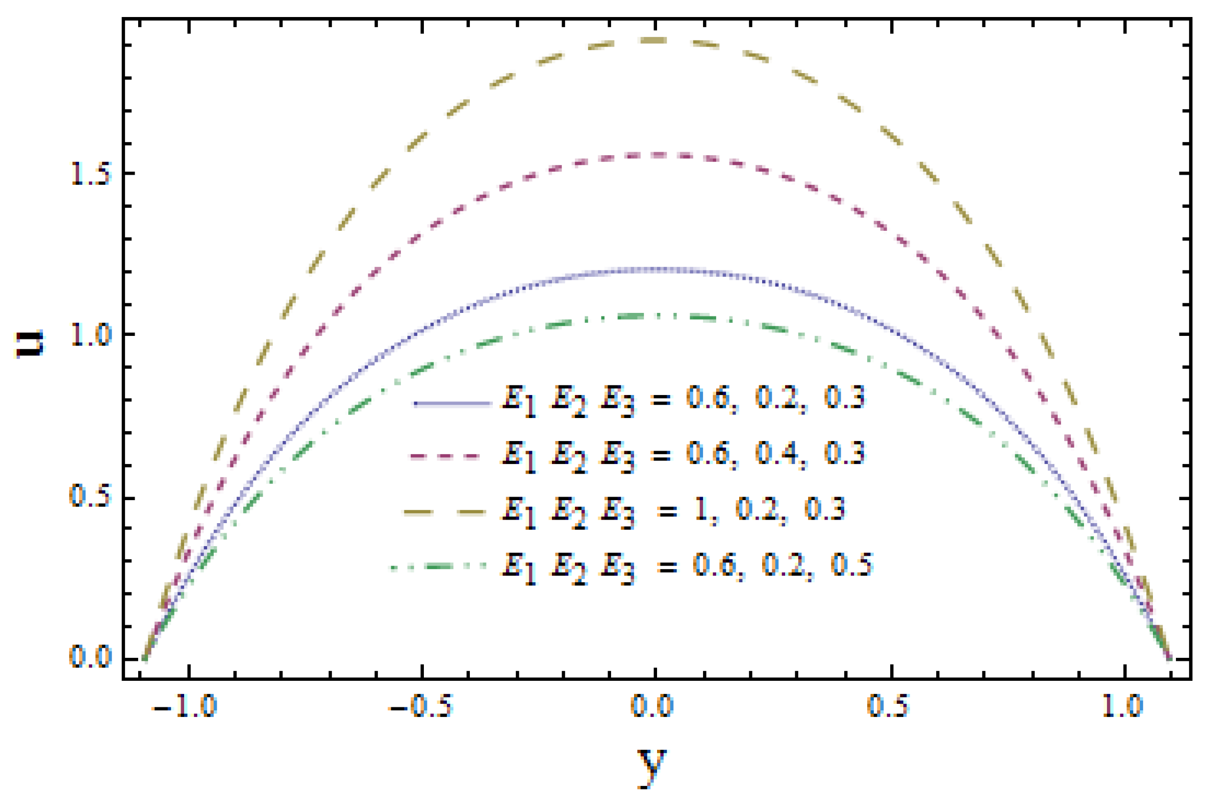
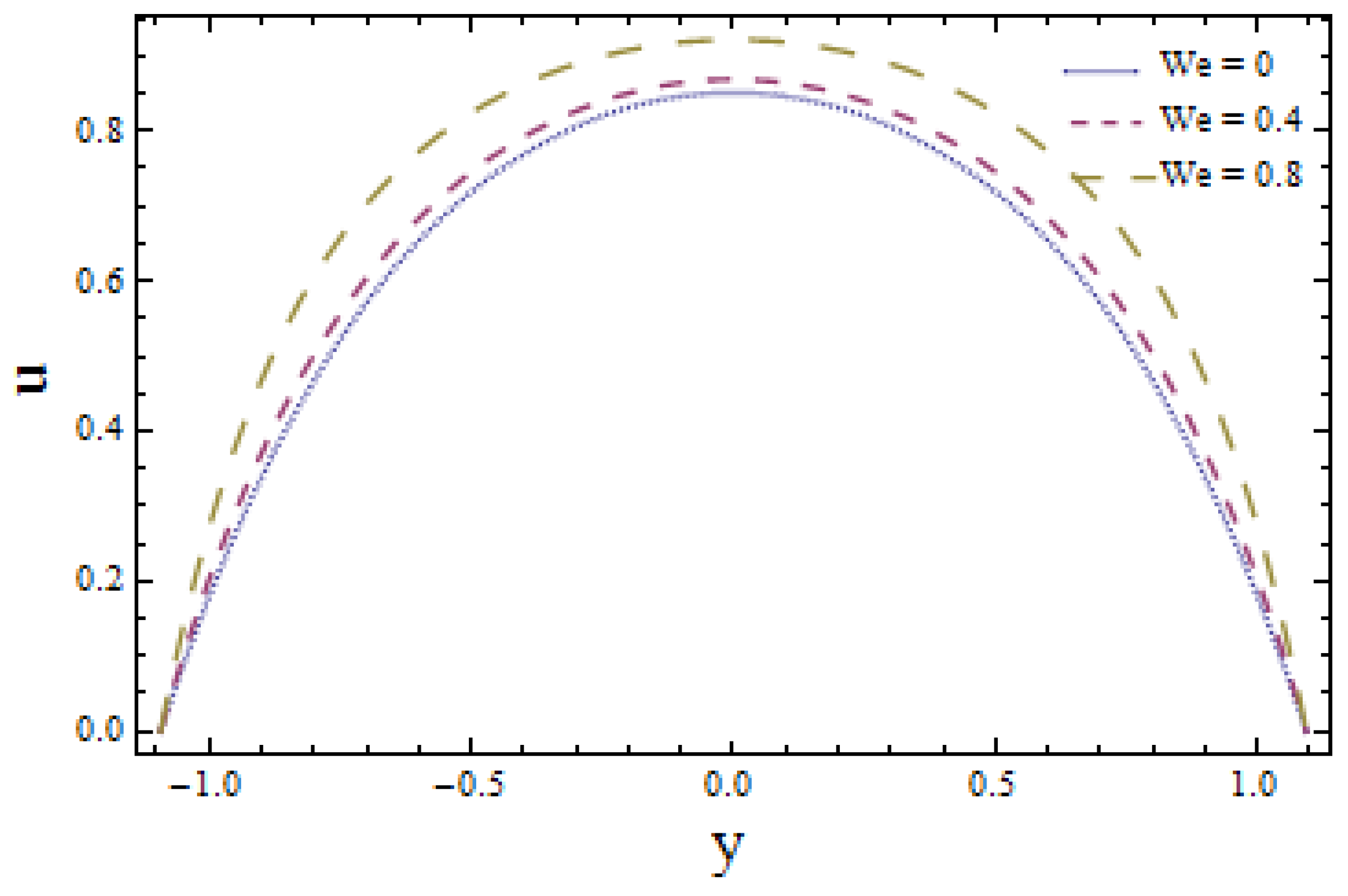
The influence of wall membrane parameters (denoted by E 1 , E 2 and E 3 ) are explored in Figure 2. Graphical results indicate that, with the increase in E 1 and E 2 , the velocity increases as compliant walls offer less resistance to the flow of fluid due to their elastic behavior. E 3 manifests the damping nature of the wall that suggests more resistance to flow velocity. As a result, the velocity decreases as E 3 increases. Figure 3 elucidates the effect of Hall parameter m on flow velocity. It is seen that ascending values of m reduce the velocity profile. Larger values of velocity in the absence of Hall parameter ( m = 0 ) are also noticed (see Figure 3). Figure 4 illustrates the decreasing behavior of velocity profile when there is a rise in power law index n. Figure 5 gives the evidence that larger values of Weissenberg number W e favor the velocity profile positively. Figure 6 depicts that larger values of Hartman number m 1 lessens the velocity of fluid as a magnetic field acts like a retarding force. This is because of its transverse direction to fluid flow.

3.2. Heat Transfer Coefficient and Fluid Temperature

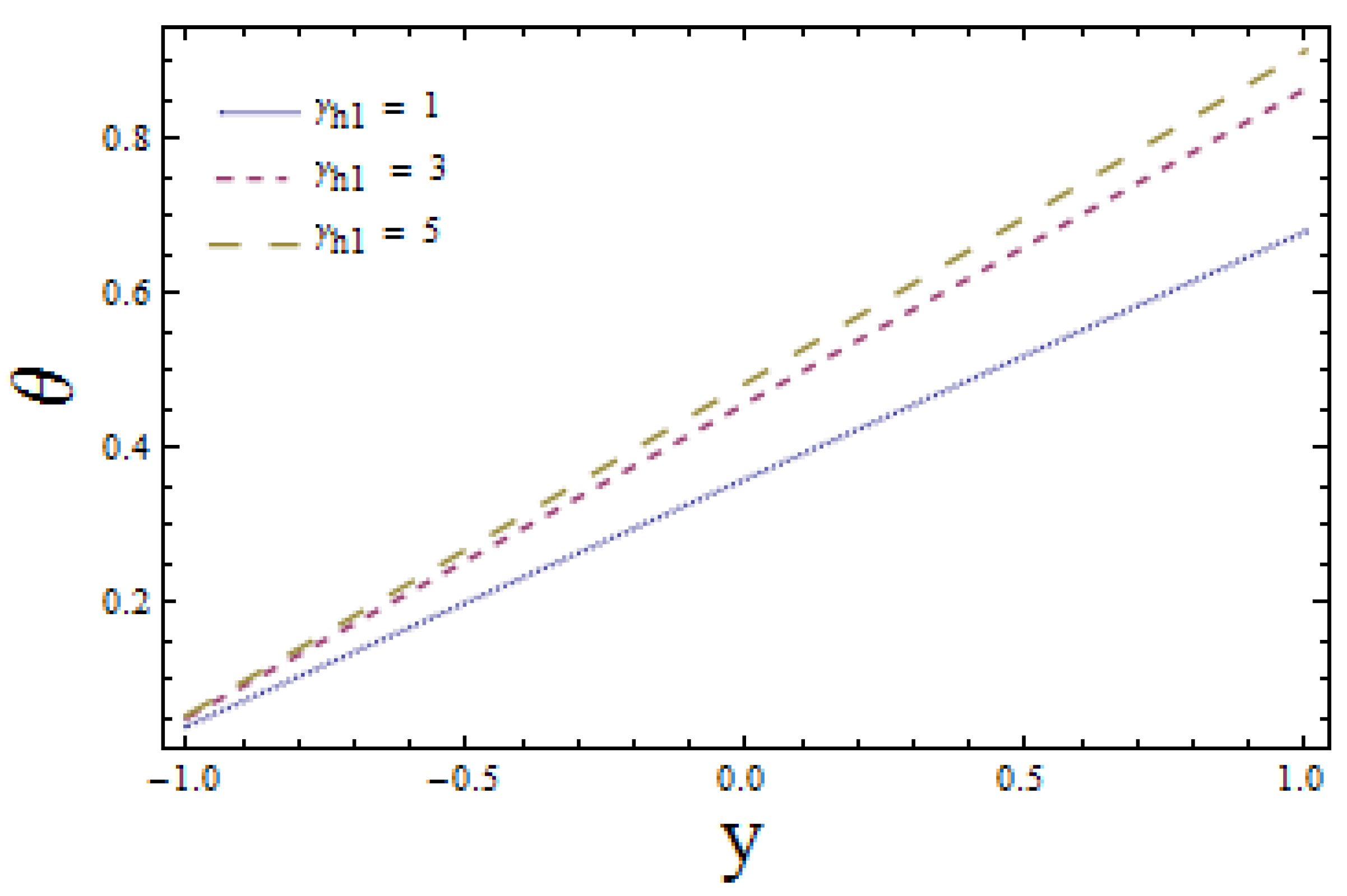
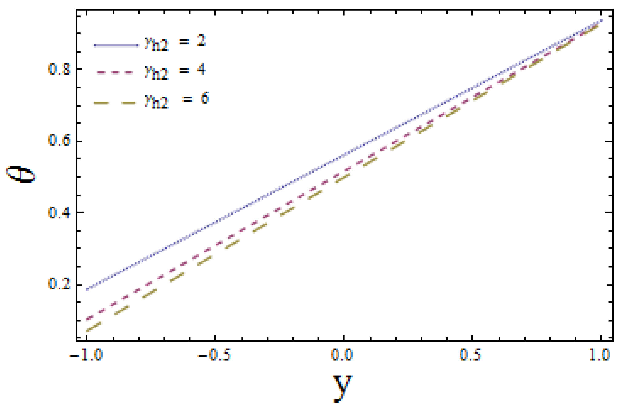
Figure 7 and Figure 8 are able to demonstrate the impacts of enhanced heat transfer Biot numbers γ h 1 and γ h 2 on lower and upper channel walls, respectively. These illustrations show the opposite impact of heat transfer Biot numbers on upper and lower channel walls. Increasing values of γ h 1 enhances the temperature profile i.e., temperature profile increases near the lower wall (see Figure 7). On the other hand, an increase in γ h 2 reduces the temperature field near the upper wall. This is in view of the fact that heat conduction decreases near a lower wall, whereas it increases near upper wall of the channel that in turns correspond to opposite results. Figure 9 and Figure 10 reveal the effects of heat transfer coefficient Z with increasing values of γ h 1 and γ h 2 . Results display the dual behavior of Z with the variations of γ h 1 and γ h 2 . An increase in values of both γ h 1 and γ h 2 favour heat transfer when x > 0.1 and reduce the transfer of heat when x < 0.1 .

3.3. Concentration Profile

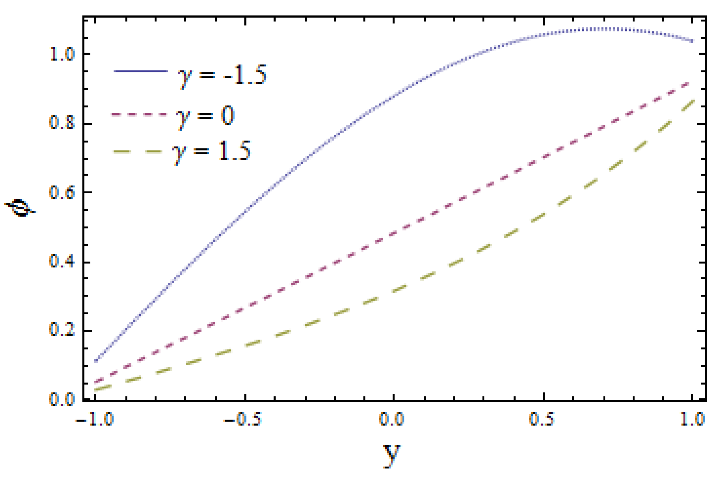
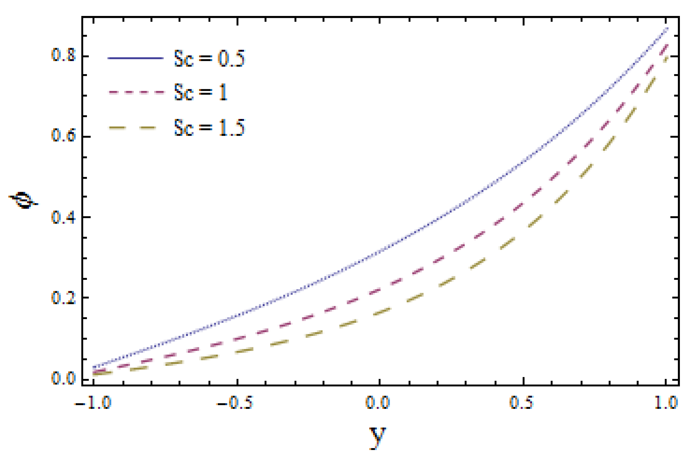
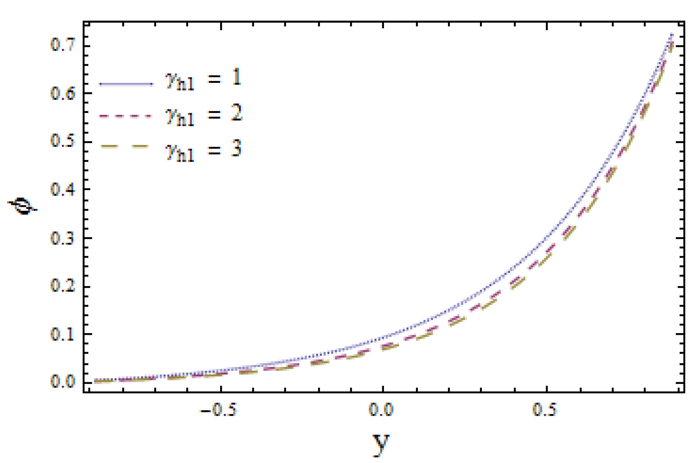
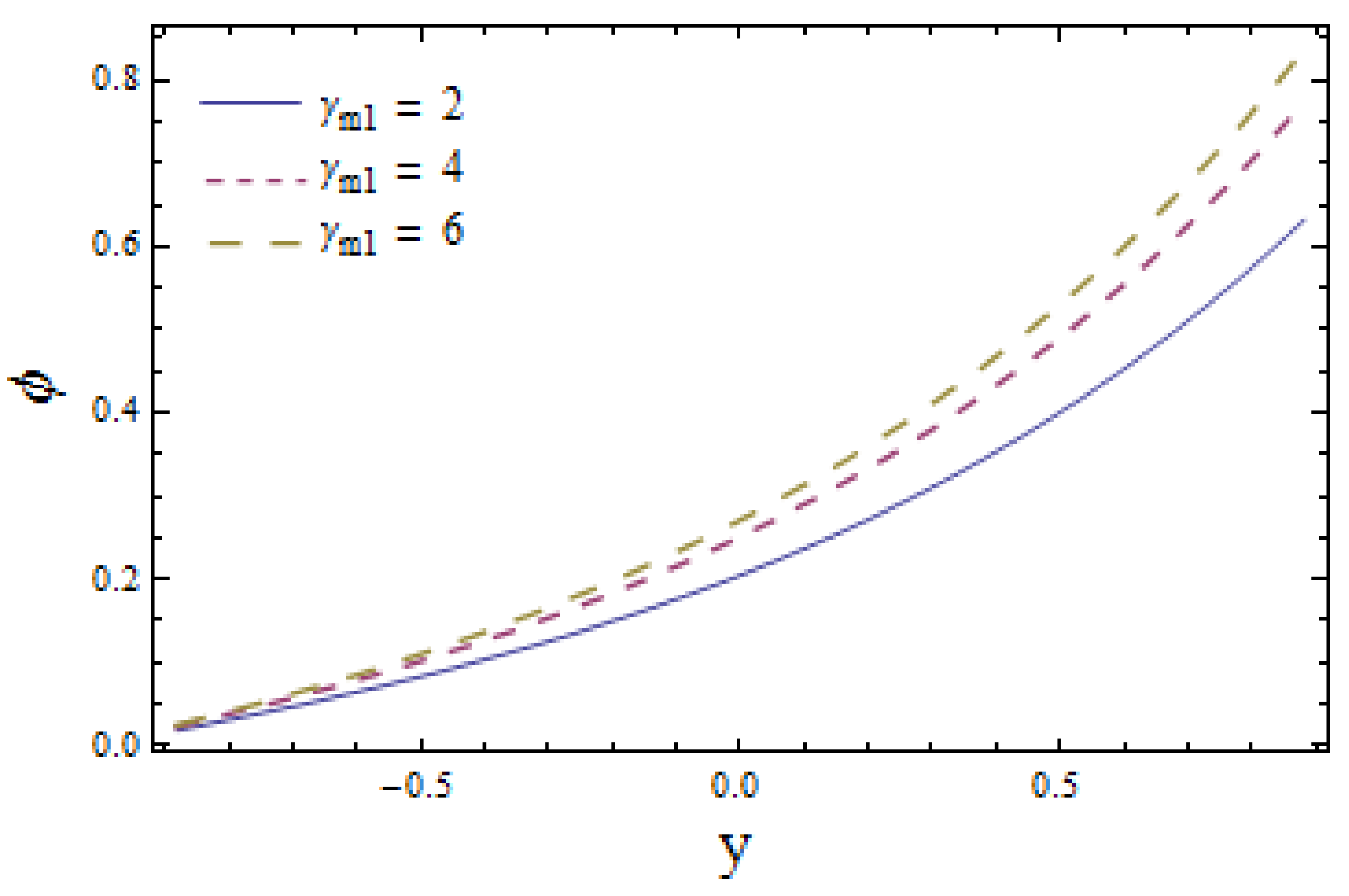
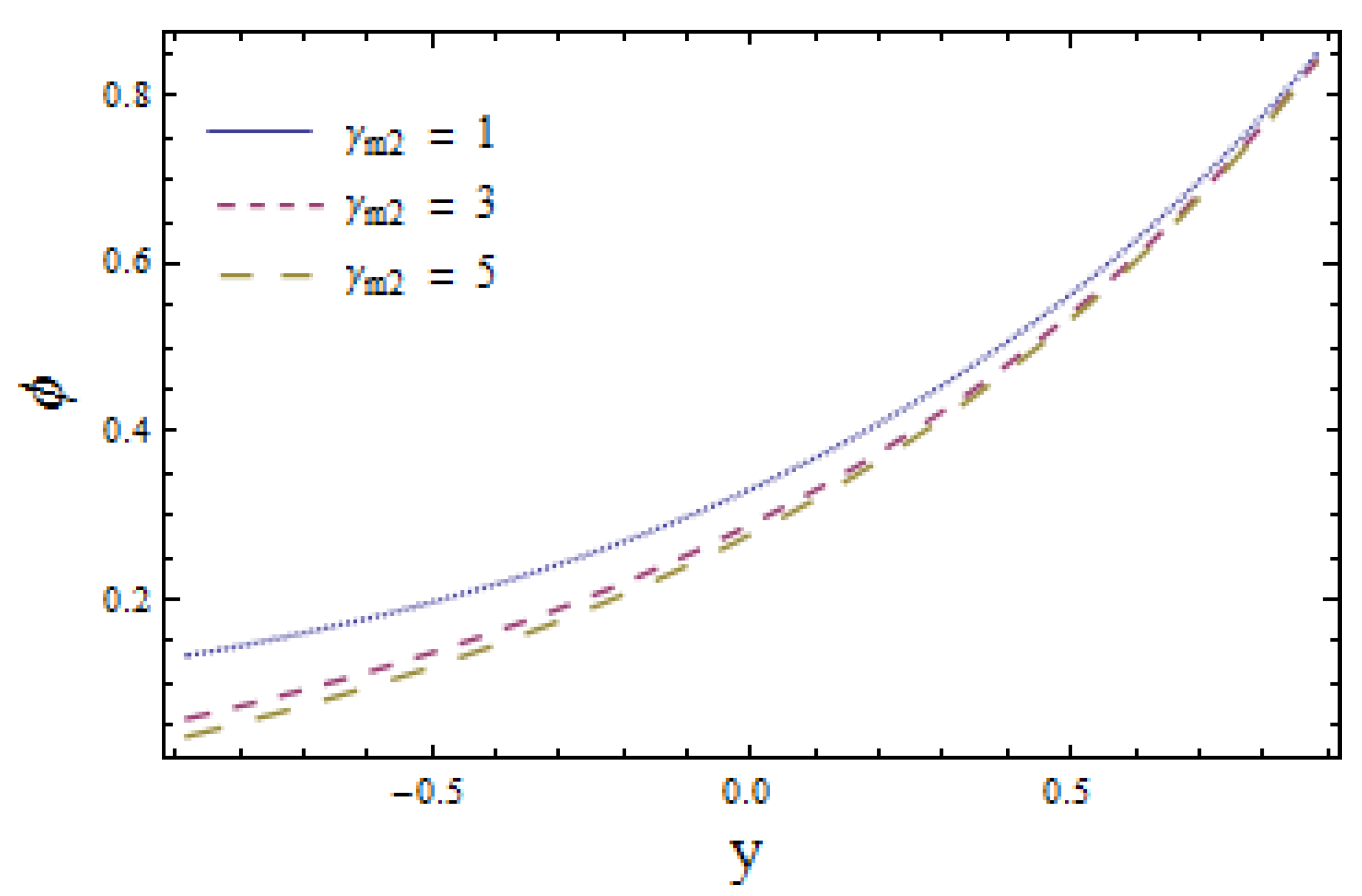
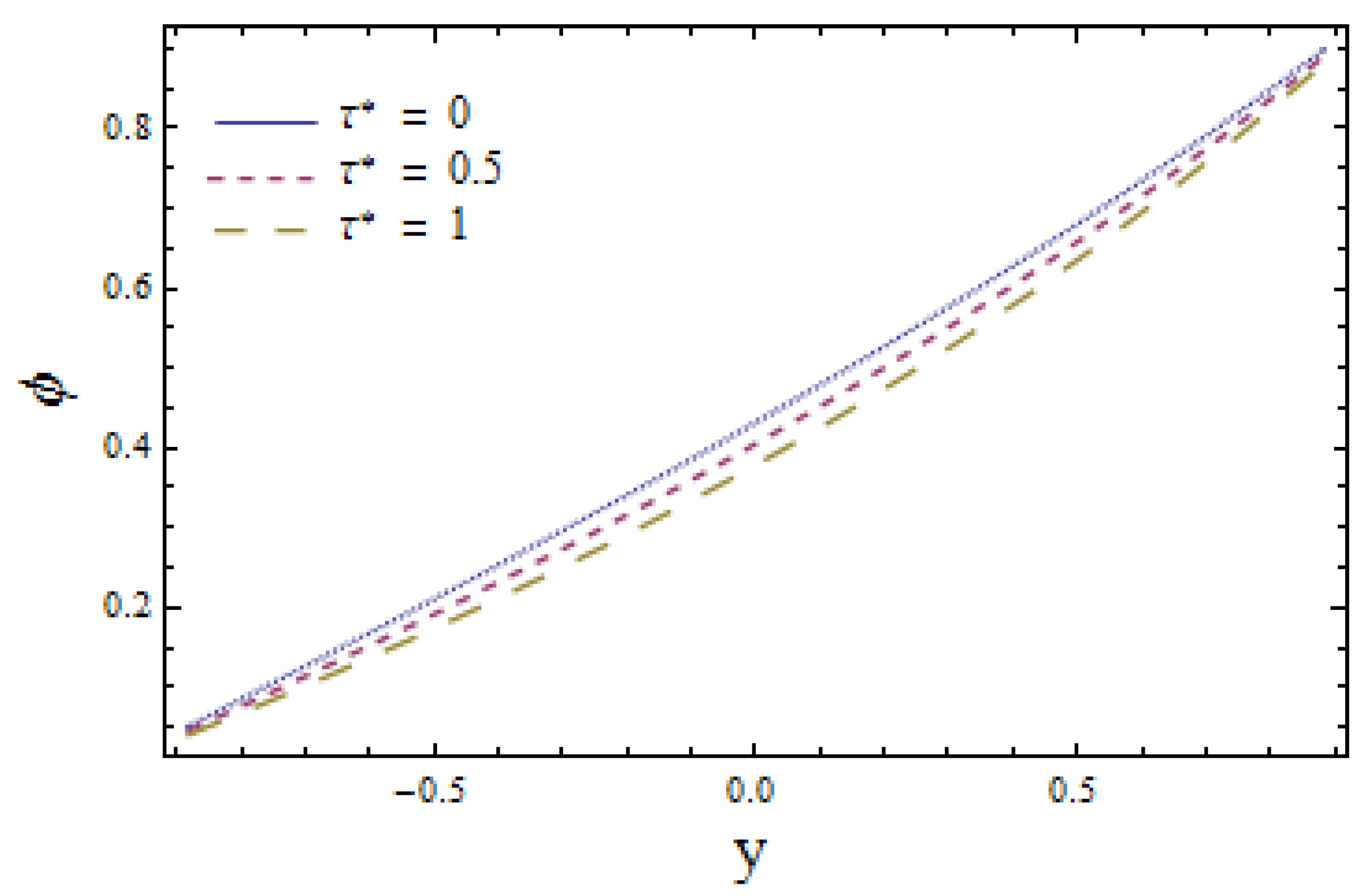
The effects of chemical reaction on concentration profile are depicted in Figure 11. Obtained results signify that the fluid concentration is higher in case of γ < 0 (a constructive chemical reaction) relative to γ > 0 (a destructive chemical reaction). The viewed result followed by the fact that the intensity of chemical reactions rises with the generation of chemical reactions. Figure 12 illustrates that larger values of Schmidt number Sc correspond to a decrease in concentration profile as higher values of Sc lessen the molecular diffusion of fluid particles. The impact of Biot numbers γ h 1 , γ h 2 , γ m 1 and γ m 2 for heat and mass are displayed in Figure 13, Figure 14, Figure 15 and Figure 16. The obtained results give similar behavior for heat transfer Biot numbers γ h 1 and γ h 2 while mass transfer Biot numbers γ m 1 and γ m 2 have adverse effects on concentration distribution (see Figure 15 and Figure 16). Ascending values of γ h 1 and γ h 2 reduce the concentration distribution (see Figure 13 and Figure 14). Conversely, the mass distribution near the lower wall is increased and diminished near the upper wall when γ m 1 is enhanced (see Figure 15 and Figure 16). The drawn results followed by the fact that increasing γ m 1 lowers the inner diffusion of fluid molecules at the upper side of the wall while increasing γ m 2 at the lower side of the wall does not correspond to reduced molecular diffusions. Enhancing the values of thermophoretic parameter τ * decays the concentration distribution, which is depicted in Figure 17. It is worth mentioning that an increase in τ * causes an increase in the temperature difference of the wall. This rise in temperature weakens the inter-molecular forces between the fluid particles, which decreases the concentration distribution among them.

3.4. Trapping Characteristics

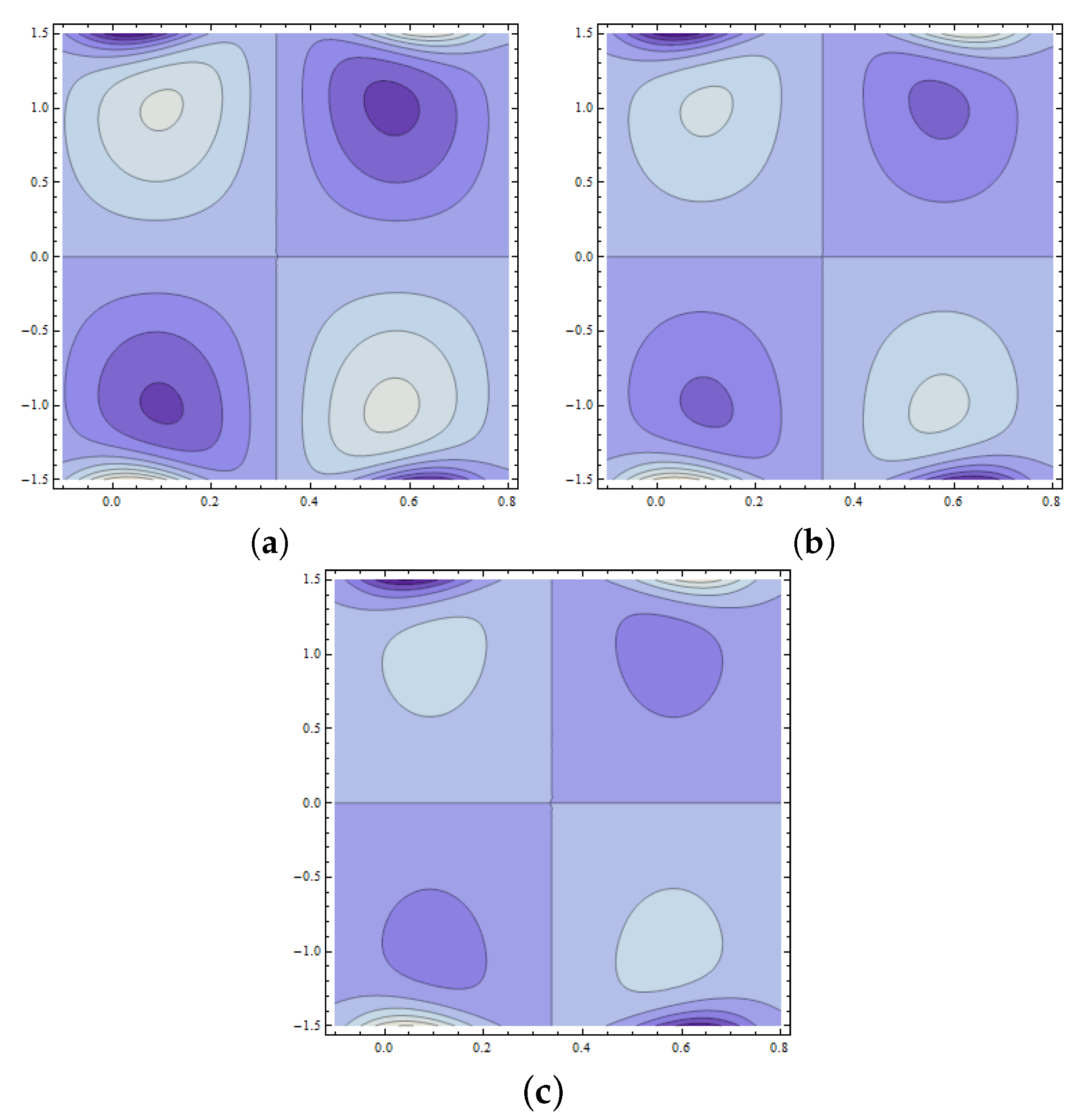
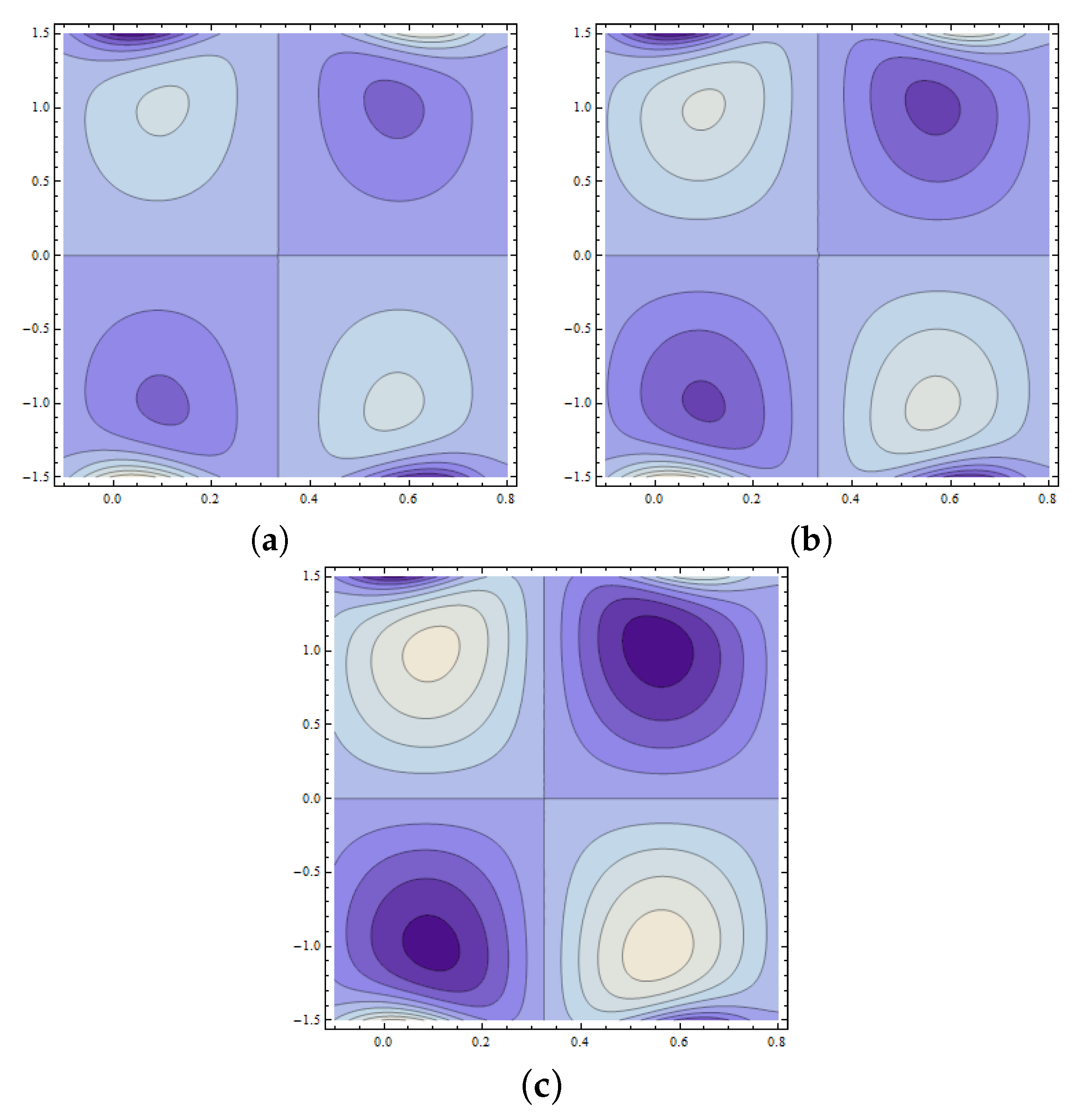
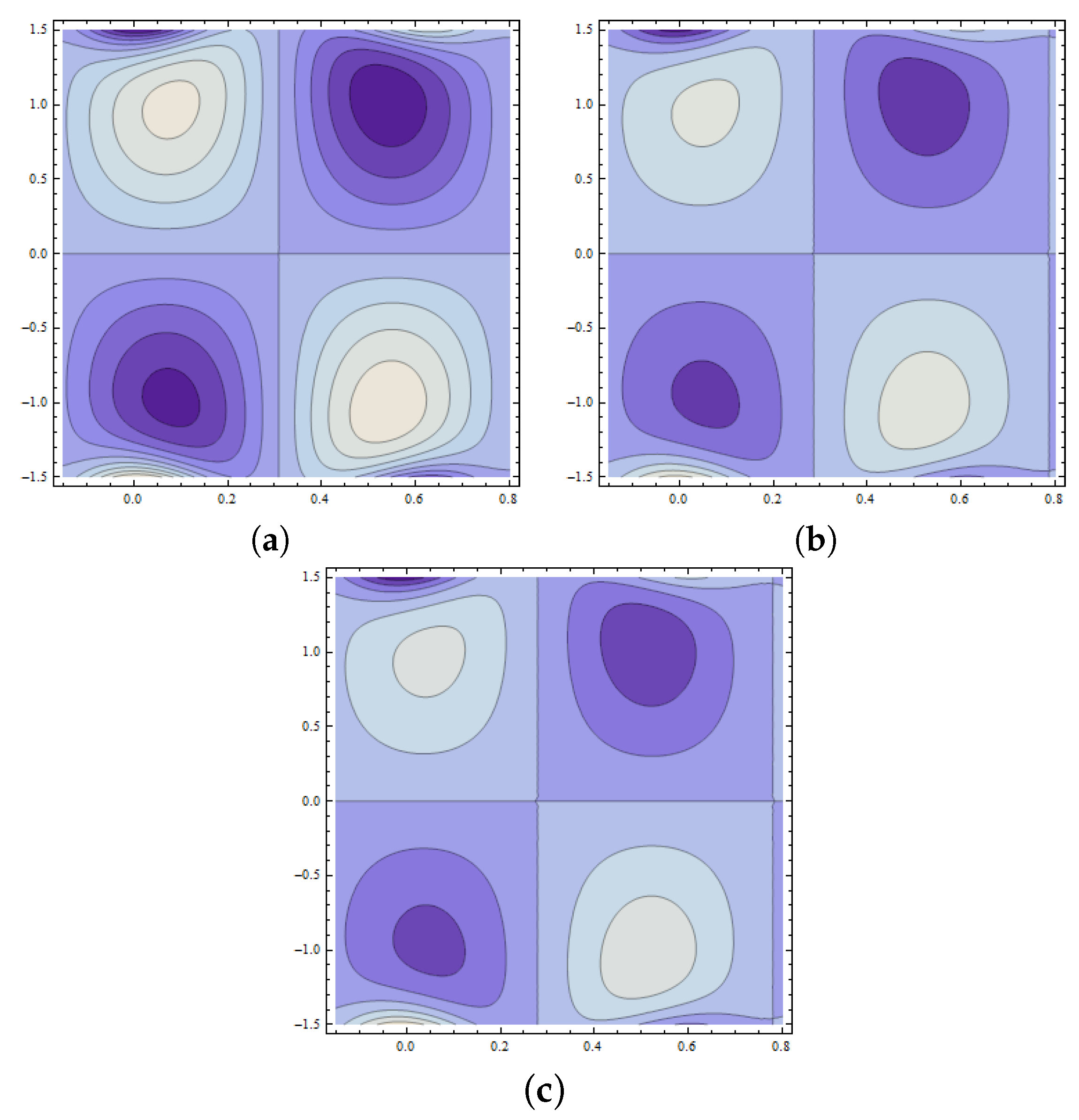
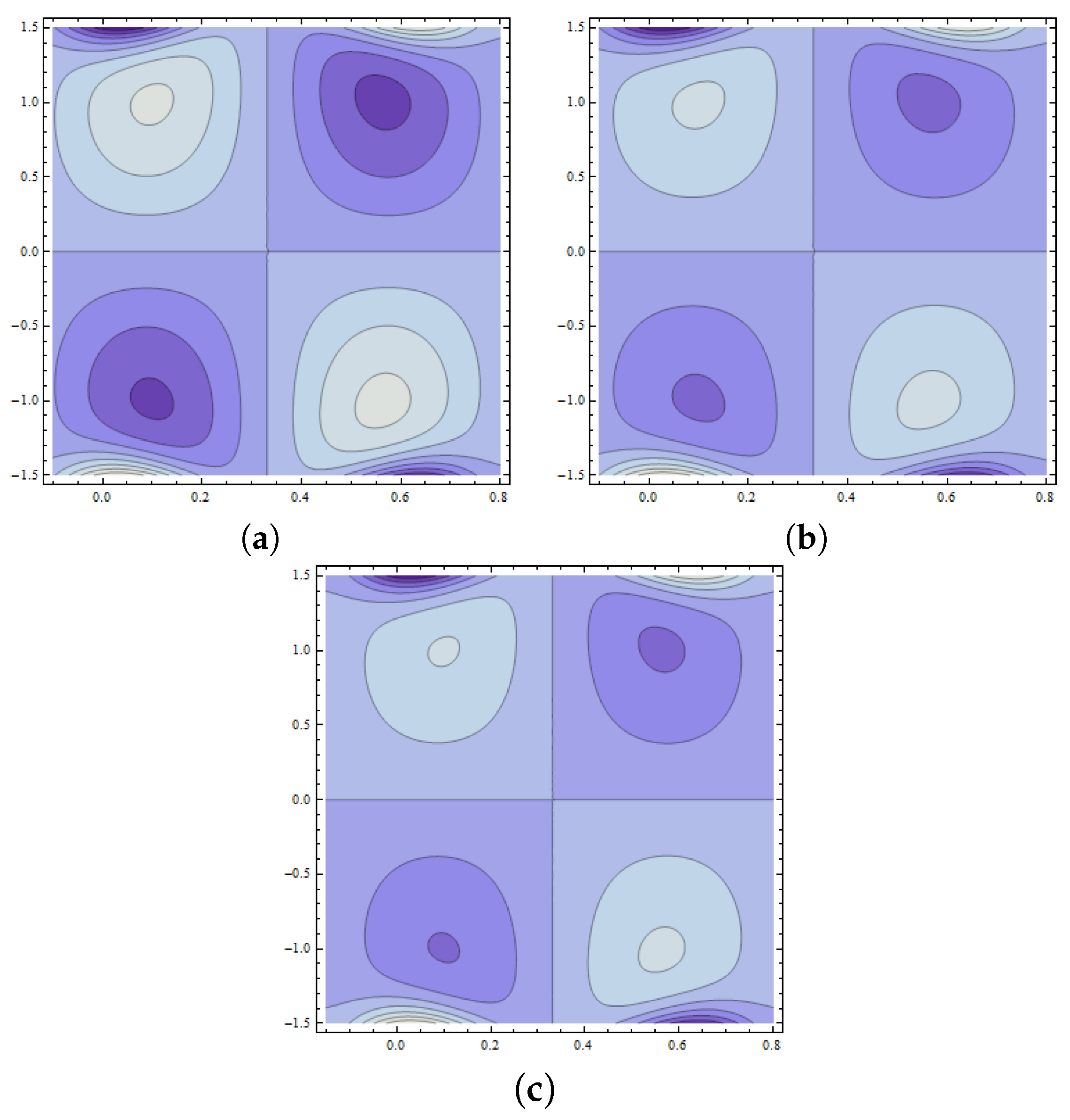
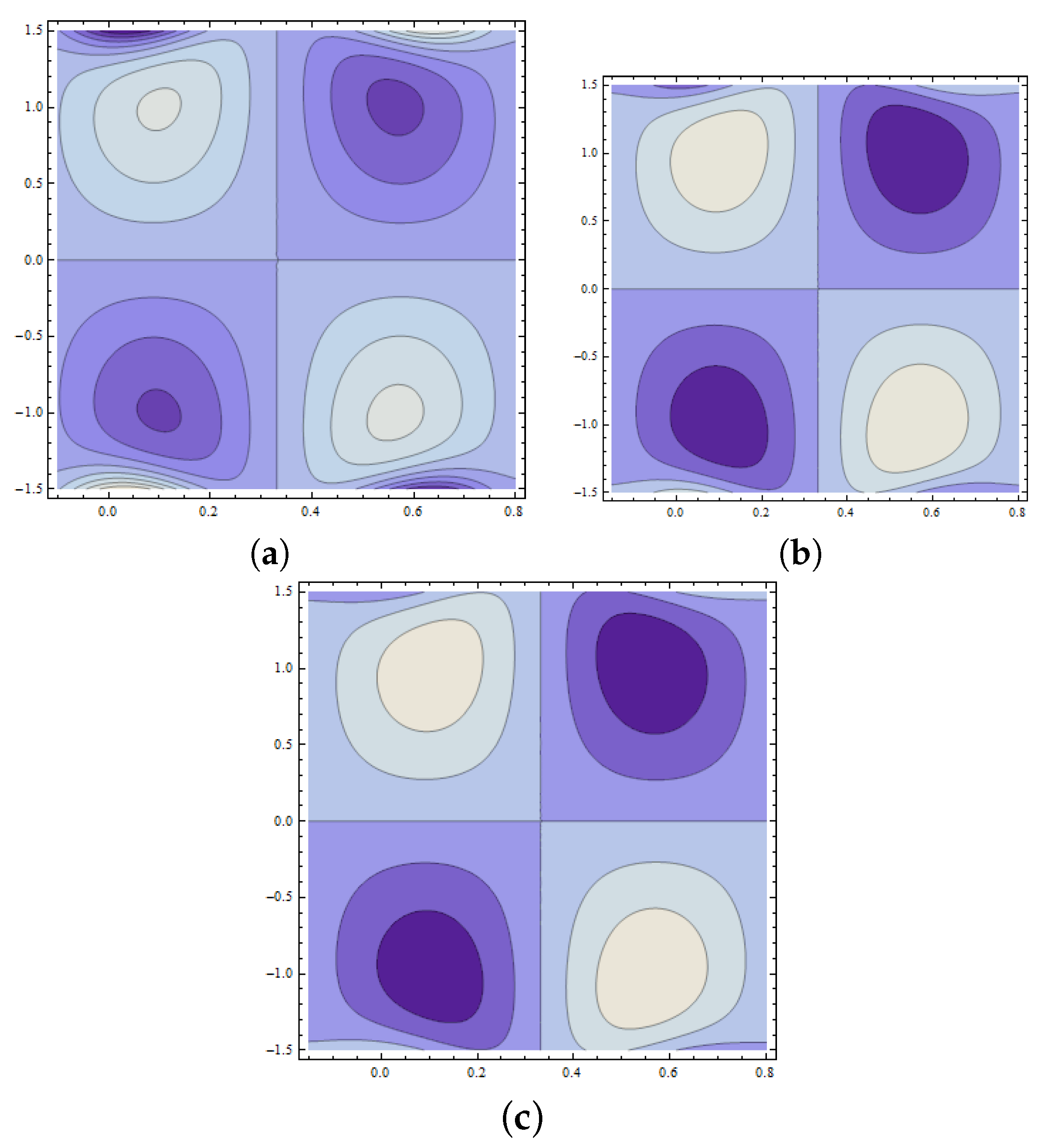
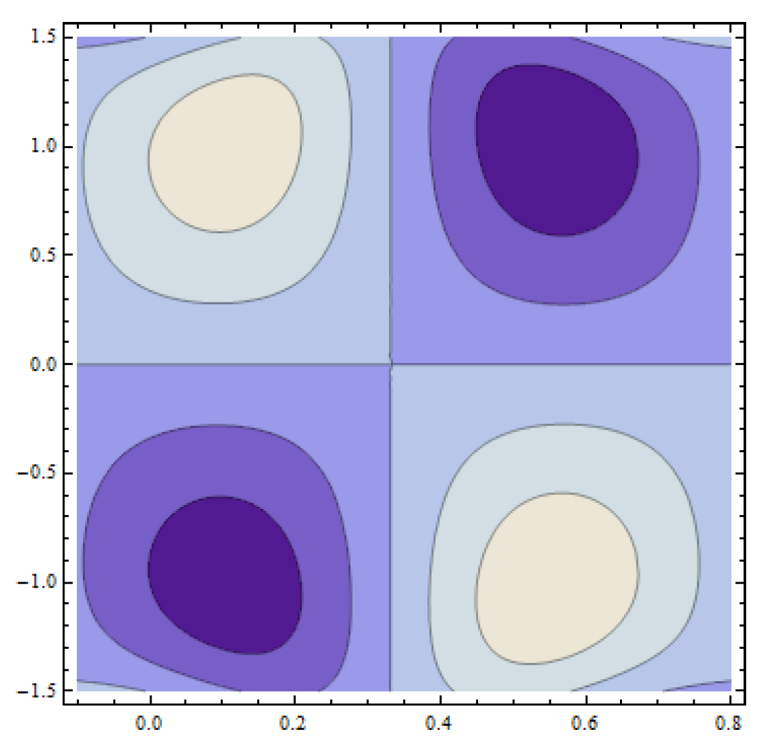
The development of trapped bolus plays a significant role in fluid flow problems. However, the trapped regions are difficult to analyze physically. This phenomenon is characterized by streamlines in peristaltic flow of fluid. Such streamlines are internally circulated and travel with the peristaltic wave. The closed form of such streamlines is termed as bolus. Figure 18a–c reveals the increasing behavior of trapped bolus with the decreasing values of wall parameter E 1 . However, the number of streamlines decreases with an increase in E 1 . Figure 19a–c displays that decreasing values of wall parameter E 2 cause an increase in number of streamlines. However, no remarkable change is observed in the size of a trapped bolus. From Figure 20a–c, the size of the trapped bolus is noted to intensify with the wall parameter E 3 . Expansion in size of trapped bolus is observed with an increase in Weissenberg number W e (see Figure 21a–c). Effects of Hartman number m 1 are displayed in Figure 22a–c. It is seen that increasing m 1 reduces the size of trapped bolus. Figure 23a–c are drawn to examine the behavior of Hall parameter m on the size of bolus. Observed results show a reduction in bolus size as well as number of streamlines. Figure 24a–c depicts that an increase in value of power law index n enlarges the size of bolus while it reduces the number of streamlines. Moreover, in thee absence of Weissenberg number ( W e = 0 ) and by taking power law index n = 1 , the results for the viscous fluid are obtained (see Figure 25).

4. Conclusions

In this article, simultaneous effects of thermal deposition and Hall current with heat and mass transfer in peristaltic flow of Carreau fluid are considered. The presented problem is modelled through convective boundary conditions on heat and mass transfer. The key results of the present research are listed below:
  • Exact reverse behavior is detected on a velocity profile and trapping for compliant wall parameters.
  • Streamlines and velocity distribution are decreasing functions of Hall parameter m.
  • Identical effects are observed for Weissenberg number and power law index on trapping phenomenon while they are exhibiting the opposite impact in the case of fluid velocity.
  • Opposite effects of Biot numbers γ h 1 and γ h 2 (for heat transfer) are observed on the temperature and concentration profiles.
  • Decrease in concentration profile corresponding to increase in Biot numbers γ m 1 and γ m 2 (for mass transfer) is observed.
  • The thermal deposition lowers the concentration distribution.
  • Dual behavior of heat transfer coefficient is observed for heat transfer Biot numbers γ h 1 and γ h 2 .

Author Contributions

Conceptualization, H.Y.; formal analysis, N.I.; investigation, A.T.; methodology, H.Y. and A.T.; software, A.T.; validation, H.Y. and N.I.; writing—original draft preparation, H.Y., N.I. and A.T.; writing—review and editing, N.I. and H.Y.; visualization, A.T. and N.I.; supervision, H.Y. All authors have read and agreed to the published version of the manuscript.

Funding

This research received no external funding.

Conflicts of Interest

The authors declare no conflict of interest.

References

  1. Latham, T.W. Fluid Motion in Peristaltic Pump. Mater’s Thesis, MIT, Cambridge, MA, USA, 1966. [Google Scholar]
  2. Shapiro, A.H.; Jafferin, M.Y.; Weinberg, S.L. Peristaltic pumping with long wavelengths at low Reynolds number. J. Fluid Mech. 1969, 35, 669. [Google Scholar] [CrossRef]
  3. Ramesh, K.; Tripathi, D.; Bhatti, M.M.; Khalique, C.M. Electro-osmotic flow of hydromagnetic dusty viscoelastic fluids in a microchannel propagated by peristalsis. J. Mol. Liq. 2020, 314, 13568. [Google Scholar] [CrossRef]
  4. Tariq, H.; Khan, A.A.; Zaman, A. Theoretical analysis of peristaltic viscous fluid with inhomogeneous dust particles. Arab. J. Sci. Eng. 2020. [Google Scholar] [CrossRef]
  5. Shit, G.C.; Ranjit, N.K. Role of slip velocity on peristaltic transport of couple stress fluid through an asymmetric non-uniform channel: Application to digestive system. J. Mol. Liq. 2016, 221, 305–315. [Google Scholar] [CrossRef]
  6. Abd elmaboud, Y.; Mekheimer, K.S. Nonlinear peristaltic transport of a second-order fluid through a porous medium. Appl. Math. Model. 2011, 35, 2695–2710. [Google Scholar] [CrossRef]
  7. Bhandari, D.S.; Tripathi, D.; Narla, V.K. Pumping flow model for couple stress fluids with a propagative membrane contraction. Int. J. Mech. Sci. 2020, 188, 105949. [Google Scholar] [CrossRef]
  8. Mehmood, O.U.; Qureshi, A.A.; Yasmin, H.; Uddin, S. Thermo-mechanical analysis of non Newtonian peristaltic mechanism: Modified heat flux model. Phys. A Statis. Mech. Appl. 2020, 550, 124014. [Google Scholar] [CrossRef]
  9. Agarwal, R.P.; Gala, S.; Ragusa, M.A. A regularity criterion in weak spaces to Boussinesq equations. Mathematics 2020, 8, 920. [Google Scholar] [CrossRef]
  10. Benbernou, S.; Gala, S.; Ragusa, M.A. On the regularity criteria for the 3D magnetohydrodynamic equations via two components in terms of BMO space. Math. Method Appl. Sci. 2014, 37, 2320–2325. [Google Scholar] [CrossRef]
  11. Ragusa, M.A.; Tachikawa, A. Regularity for minimizers for functionals of double phase with variable exponents. Adv. Nonlinear Anal. 2020, 9, 710–728. [Google Scholar] [CrossRef]
  12. Ali, N.; Hayat, T. Peristaltic motion of a Carreau fluid in an asymmetric channel. Appl. Math. Comput. 2007, 193, 535–552. [Google Scholar] [CrossRef]
  13. Ellahi, R.; Riaz, A.; Nadeem, S.; Ali, M. Peristaltic flow of Carreau fluid in a rectangular duct through a porous medium. Math. Probl. Eng. 2012, 2012, 329639. [Google Scholar] [CrossRef]
  14. Hayat, T.; Hina, S.; Hendi, A.A.; Asghar, S. Influence of compliant walls on peristaltic motion with heat/mass transfer and chemical reaction. Int. J. Heat Mass Transf. 2012, 55, 3386–3394. [Google Scholar]
  15. Hina, S.; Mustafa, M.; Hayat, T.; Alotaibi, N.D. On peristaltic motion of pseudoplastic fluid in a curved channel with heat/mass transfer and wall properties. Appl. Math. Comput. 2015, 263, 378–391. [Google Scholar] [CrossRef]
  16. Srinivas, S.; Gayathri, R.; Kothandapani, M. Mixed convective heat and mass transfer in an asymmetric channel with peristalsis. Commun. Nonlinear Sci. Numer. Simul. 2011, 16, 1845–1862. [Google Scholar] [CrossRef]
  17. Waqas, M.; Farooq, M.; Khan, M.I.; Alsaedi, A.; Hayat, T.; Yasmeen, T. Magnetohydrodynamic (MHD) mixed convection flow of micropolar liquid due to nonlinear stretched sheet with convective condition. Int. J. Heat Mass Transf 2016, 102, 766–772. [Google Scholar] [CrossRef]
  18. Hayat, T.; Yasmin, H.; Al-Yami, M. Soret and Dufour effects in peristaltic transport of physiological fluid with chemical reaction: A mathematical analysis. Comput. Fluids 2014, 89, 242–253. [Google Scholar] [CrossRef]
  19. Yasmin, H.; Farooq, S.; Awais, M.; Alsaedi, A.; Hayat, T. Significance of heat and mass process in peristalsis of a rheological material. Heat Trans. Res. 2019, 50, 1561–1580. [Google Scholar] [CrossRef]
  20. Yasmin, H.; Hayat, T.; Alsaedi, A.; Alsulami, H.H. Peristaltic flow of Johnson-Segalman fluid in asymmetric channel with convective boundary conditions. Appl. Math. Mech.-Engl. Ed. 2014, 35, 697–716. [Google Scholar] [CrossRef]
  21. Hussain, Q.; Hayat, T.; Asghar, S.; Alsulami, H.H. Mixed convective peristaltic transport in a vertical channel with Robin’s condition. J. Braz. Soc. Mech. Sci. Eng. 2014, 36, 681–695. [Google Scholar] [CrossRef]
  22. Hayat, T.; Yasmin, H.; Ahmed, B.; Chen, B. Simultaneous effects of convective conditions and nanoparticles on peristaltic motion. J. Mol. Liq. 2014, 193, 74–82. [Google Scholar] [CrossRef]
  23. Hayat, T.; Qasim, M. Influence of thermal radiation and Joule heating on MHD flow of a Maxwell fluid in the presence of thermophoresis. Int. J. Heat Mass Transf. 2010, 53, 4780–4788. [Google Scholar] [CrossRef]
  24. Hayat, T.; Shehzad, S.A.; Alhuthali, M.S.; Alsaedi, A. Thermophoresis particle deposition in mixed convection three-dimensional radiative flow of an Oldroyd-B fluid. J. Taiwan Inst. Chem. Eng. 2014, 45, 787–794. [Google Scholar]
  25. Hayat, T.; Awais, M.; Asghar, S. Radiative effects in a three dimensional flow of MHD Eyring-Powell fluid. J. Egyp. Math. Soc. 2013, 21, 379–384. [Google Scholar] [CrossRef] [Green Version]
  26. Sheikholeslami, M.; Hatami, M.; Ganji, D.D. Nanofluid flow and heat transfer in a rotating system in the presence of a magnetic field. J. Mol. Liq. 2014, 190, 112–120. [Google Scholar] [CrossRef]
  27. Ahmed, R.; Ali, N.; Khan, S.U.; Tlili, I. Numerical simulations for mixed convective hydromagnetic peristaltic flow in a curved channel with joule heating features. AIP Adv. 2020, 10, 075303. [Google Scholar] [CrossRef]
  28. Mekheimer, K.S.; Komy, S.R.; Abdelselam, S.I. Simultaneous effects of magnetic field and space porosity on compressible Maxwell fluid transport induced by surface acoustic wave in a microchannel. Chin. Phys. B 2013, 22, 124702–124710. [Google Scholar] [CrossRef]
  29. Abd elmaboud, Y. Influence of induced magnetic field on peristaltic flow in an annulus. Commun. Nonlinear Sci. Numer. Simul. 2012, 17, 685–698. [Google Scholar] [CrossRef]
  30. Machireddy, G.R.; Kattamreddy, V.R. Impact of velocity slip and Joule heating on MHD peristaltic flow through a porous medium with chemical reaction. J. Niger. Math. Soc. 2016, 35, 227–244. [Google Scholar] [CrossRef] [Green Version]
  31. Reddy, M.G. Heat and mass transfer on magnetohydrodynamic peristaltic fluid in a porous medium with partial slip. Alex. Eng. J. 2016, 55, 1225–1234. [Google Scholar] [CrossRef]
  32. Hayat, T.; Nisar, Z.; Ahmad, B.; Yasmin, H. Simultaneous effects of slip and wall properties on MHD peristaltic motion of nanofluid with Joule heating. J. Magn. Magn. Mat. 2015, 395, 48–58. [Google Scholar] [CrossRef]
  33. SKoumy, R.E.; Barakat, E.S.I.; Abdelsalam, S.I. Hall and porous boundaries effects on peristaltic transport through porous medium of Maxwell model. Transp. Porous Med. 2012, 94, 643–658. [Google Scholar]
  34. Abo-Eldahab, E.; Barakat, E.; Nowar, K. Hall currents and heat transfer effects on peristaltic transport in a vertical asymmetric channel through a porous medium. Math. Prob. Eng. 2012, 2012, 840203. [Google Scholar] [CrossRef]
  35. Hayat, T.; Ali, N.; Asghar, S. Hall effects on peristaltic flow of a Maxwell fluid in a porous medium. Phys. Lett. A 2007, 363, 397–403. [Google Scholar] [CrossRef]
  36. Javed, M. A mathematical framework for peristaltic mechanism of non-Newtonian fluid in an elastic heated channel with Hall effect, Multidis. Model. Mat. Struct. 2020. [Google Scholar] [CrossRef]
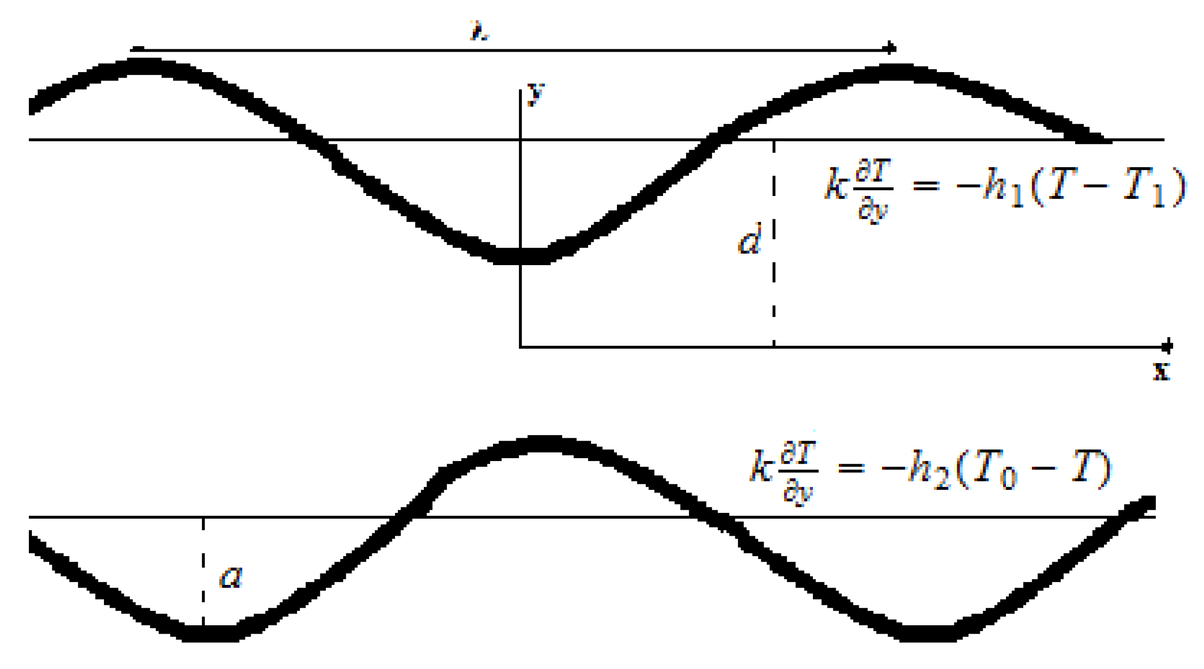
Figure 1. Schematic representation of the problem.
Mathematics 08 01710 g001
Figure 2. Velocity u v e r s u s y with E 1 , E 2 , E 3 when ϵ = 0.1 , x = 0.2 , t = 0.01 , W e = 0.03 , n = 0.4 , m = 0.04 and m 1 = 2 .
Mathematics 08 01710 g002
Figure 3. Velocity u v e r s u s y with m when x = 0.2 , ϵ = 0.1 , t = 0.01 , E 1 = 0.4 , E 2 = 0.2 , E 3 = 0.3 , W e = 0.03 , n = 0.4 and m 1 = 2 .
Mathematics 08 01710 g003
Figure 4. Velocity u v e r s u s y with n when ϵ = 0.1 , x = 0.2 , t = 0.01 , E 1 = 0.4 , E 2 = 0.2 , E 3 = 0.3 , m = 0.04 , W e = 0.03 and m 1 = 2 .
Mathematics 08 01710 g004
Figure 5. Velocity u v e r s u s y with W e when ϵ = 0.1 , x = 0.2 , t = 0.01 , E 1 = 0.4 , E 2 = 0.2 , E 3 = 0.3 , m = 0.04 , n = 0.4 and m 1 = 2 .
Mathematics 08 01710 g005
Figure 6. Velocity u v e r s u s y with m 1 when ϵ = 0.1 , x = 0.2 , t = 0.01 , E 1 = 0.4 , E 2 = 0.2 , E 3 = 0.3 , m = 0.04 , n = 0.4 and W e = 0.03 .
Mathematics 08 01710 g006
Figure 7. Temperature θ versus y for γ h 1 when ϵ = 0.2 , x = 0.1 , t = 0.1 and γ h 2 = 8 .
Mathematics 08 01710 g007
Figure 8. Temperature θ versus y for γ h 2 when ϵ = 0.2 , x = 0.1 , t = 0.1 and γ h 1 = 8 .
Mathematics 08 01710 g008
Figure 9. Heat transfer Z versus y for γ h 1 when ϵ = 0.2 , t = 0.1 and γ h 2 = 8 .
Mathematics 08 01710 g009
Figure 10. Heat transfer Z versus y for γ h 2 when ϵ = 0.2 , t = 0.1 and γ h 1 = 6 .
Mathematics 08 01710 g010
Figure 11. Mass concentration ϕ versus y for γ when ϵ = 0.2 , τ * = 0.1 , x = 0.1 , t = 0.1 , γ h 1 = 6 , γ h 2 = 8 , γ m 1 = 6 , γ m 2 = 8 and S c = 0.5 .
Mathematics 08 01710 g011
Figure 12. Mass concentration ϕ versus y for S c when ϵ = 0.2 , τ * = 0.1 , x = 0.1 , t = 0.1 , γ h 1 = 6 , γ h 2 = 8 , γ m 1 = 6 , γ m 2 = 8 and γ = 1.5 .
Mathematics 08 01710 g012
Figure 13. Mass concentration ϕ versus y for γ h 1 when ϵ = 0.2 , τ * = 2 , x = 0.1 , t = 0.1 , γ h 2 = 8 , γ m 1 = 6 , γ m 2 = 8 , γ = 1 and S c = 2 .
Mathematics 08 01710 g013
Figure 14. Mass concentration ϕ versus y for γ h 2 when ϵ = 0.2 , τ * = 2 , x = 0.1 , t = 0.1 , γ h 1 = 6 , γ m 1 = 6 , γ m 2 = 8 , γ = 1 and S c = 2 .
Mathematics 08 01710 g014
Figure 15. Mass concentration ϕ versus y for γ m 1 when ϵ = 0.2 , τ * = 2 , x = 0.1 , t = 0.1 , γ h 1 = 6 , γ h 2 = 8 , γ m 2 = 8 , γ = 1 and S c = 0.5 .
Mathematics 08 01710 g015
Figure 16. Mass concentration ϕ versus y for γ m 2 when ϵ = 0.2 , τ * = 2 , x = 0.1 , t = 0.1 , γ h 1 = 6 , γ h 2 = 8 , γ m 1 = 6 , γ = 1 and S c = 0.5 .
Mathematics 08 01710 g016
Figure 17. Mass concentration ϕ versus y for τ * when ϵ = 0.2 , x = 0.1 , t = 0.1 , γ h 1 = 6 , γ h 2 = 8 , γ m 1 = 6 , γ m 2 = 8 , γ = 1.5 and S c = 0.5 .
Mathematics 08 01710 g017
Figure 18. Pattern of streamlines when ϵ = 0.1 , t = 0.1 , m = 0.04 , m 1 = 2 , E 2 = 0.2 , E 3 = 0.3 , n = 0.4 and W e = 0.4 with (a) E 1 = 0.2 , (b) E 1 = 0.3 , (c) E 1 = 0.4 .
Mathematics 08 01710 g018
Figure 19. Pattern of streamlines when ϵ = 0.1 , t = 0.1 , m = 0.04 , m 1 = 2 , E 1 = 0.1 , E 3 = 0.3 , n = 0.4 and W e = 0.4 with (a) E 2 = 0.4 , (b) E 2 = 0.3 , (c) E 2 = 0.2 .
Mathematics 08 01710 g019
Figure 20. Pattern of streamlines when ϵ = 0.1 , t = 0.1 , m = 0.04 , m 1 = 2 , E 1 = 0.1 , E 2 = 0.2 , n = 0.4 and W e = 0.4 with (a) E 3 = 0.5 , (b) E 3 = 0.8 , (c) E 3 = 0.9 .
Mathematics 08 01710 g020
Figure 21. Pattern of streamlines when ϵ = 0.1 , t = 0.1 , m = 0.04 , m 1 = 2 , E 1 = 0.2 , E 2 = 0.2 , E 3 = 0.3 and n = 0.4 with (a) W e = 0.4 , (b) W e = 0.2 , (c) W e = 0.1 .
Mathematics 08 01710 g021
Figure 22. Pattern of streamlines when ϵ = 0.1 , t = 0.1 , m = 0.04 , n = 0.4 , E 1 = 0.2 , E 2 = 0.2 , E 3 = 0.3 and W e = 0.4 with (a) m 1 = 1 , (b) m 1 = 1.7 , (c) m 1 = 2 .
Mathematics 08 01710 g022
Figure 23. Pattern of streamlines when ϵ = 0.1 , t = 0.1 , m 1 = 2 , E 1 = 0.2 , E 2 = 0.2 , E 3 = 0.3 , n = 0.4 and W e = 0.4 with (a) m = 0 , (b) m = 1.5 , (c) m = 2 .
Mathematics 08 01710 g023
Figure 24. Pattern of streamlines when ϵ = 0.1 , t = 0.1 , m 1 = 2 , E 1 = 0.2 , E 2 = 0.2 , E 3 = 0.3 , n = 0.4 , m = 0.04 and W e = 0.4 with (a) n = 0.4 , (b) n = 0.8 , (c) n = 0.9 .
Mathematics 08 01710 g024
Figure 25. Pattern of streamlines when ϵ = 0.1 , t = 0.1 , m = 0.04 , m 1 = 2 , E 1 = 0.2 , E 2 = 0.2 , E 3 = 0.3 , W e = 0 and n = 1 .
Mathematics 08 01710 g025