Article

Optimal Design of Isothermal Sloshing Vessels by Entropy Generation Minimization Method

by
Mohammad Yaghoub Abdollahzadeh Jamalabadi
1,2
1
Department for Management of Science and Technology Development, Ton Duc Thang University, Ho Chi Minh City 700000, Vietnam
2
Faculty of Civil Engineering, Ton Duc Thang University, Ho Chi Minh City 700000, Vietnam
Mathematics 2019, 7(5), 380; https://doi.org/10.3390/math7050380
Submission received: 20 March 2019 / Revised: 6 April 2019 / Accepted: 22 April 2019 / Published: 26 April 2019
(This article belongs to the Special Issue Computational Fluid Dynamics 2020)

Abstract

:
In this manuscript, the optimal design of geometry for a forced sloshing in a rigid container based on the entropy generation minimization (EGM) method is presented. The geometry of the vessel considered here is two dimensional rectangular. Incompressible inviscid fluid undergoes horizontal harmonic motion by interaction with a rigid tank. The analytical solution of a fluid stream function is obtained and benchmarked by Finite element results. A parameter study of the aspect ratio, amplitude, and frequency of the horizontal harmonic motion is performed. As well, an analytical solution for the total entropy generation in the volume is presented and discussed. The total entropy generation is compared with the results of the Reynolds-Averaged Navier–Stokes (RANS) solver and the Volume-of-Fluid (VOF) method). Then, the effect of parameters is studied on the total entropy generated by sway motion. Finally, the results show that, based on the excitation frequency, an optimal design of the tank could be found.

1. Introduction

The ship maneuver-induced motion in the partially-filled tanks by liquid, sloshing poses a thoughtful danger to the controllability and stability of this phenomenon. The entropy generation minimization method is used for the design of fluid flow motion system [1] as well as thermal systems [2,3,4] in recent years. Although the method is applied to the thermodynamic optimization of many finite-size systems and finite-time processes [5], the application in isothermal fluid flow is rare [6]. For the specific case of sloshing, as such systems are used to damping the solid motion [7], the minimization of entropy could not be a true objective function for optimization. Even if a new engineering application has emerged in the future where the minimization of the entropy in sloshing fluid is the aim, the fluid cannot consider as a complete thermodynamic system. The fluid motion is caused by a solid structure consists of internal damping which causes entropy generation. The entropy generation in an isothermal wall container could be a measure of viscous dissipation which produces heat and could cause to danger in flammable liquids.
The analytical solution of a similar problem was presented by Ibrahim [8]. The liquid sloshing dynamics of a liquid in a vessel with horizontal excitation was presented Ibrahim [8] while the entropy generation was not discussed. Ikegawa studied the fluid flow problem motion of a rigid container excited by a horizontal harmonic acceleration with Finite Element Methods [9]. His results used in many texts as a benchmark [1]. Damping of surface waves in an incompressible liquid is studied by Case and Parkinson [10].
Jamalabadi et al. [11] found the optimal design of circular baffles in the sloshing problem occurred in a rectangular tank which is horizontally coupled by a one-story structure. Their method was pure numeric, and the optimization was based on the vibration suppression of the liquid motion. Although the problem is a classic case [12,13,14,15,16,17,18,19,20,21,22,23,24,25], the study of its exergy is discussed comprehensively in rare studies [1,26]. The entropy analysis of the flow systems is performed in many flow motions [27,28,29,30,31,32,33,34], as well and the recent developments in fluid modeling [35,36,37,38,39].
The aim of the current paper is to derive an analytical expression for entropy generation isothermal sloshing phenomenon and discuss the use of entropy generation minimization for such systems. The analytical expression for entropy generation in the rectangular tanks is obtained for the first time in the rectangular storage tank.

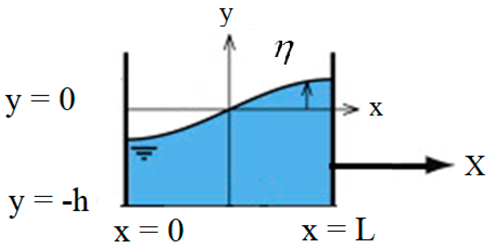
2. Mathematical Modeling

Consider a rigid rectangular tank as the physical domain of this research with length L, base at y = −h, free surface y = 0. Figure 1 shows the schematic of the problem with Coordinate system. As a first approximation the fluid motion can considered by the use of velocity potential. The replace of velocity potential in the continuity Equation ( . V = u x + v y = 0 ) leads to Laplace equation as, (see Equation 1.23 in [8])
2 ϕ x 2 + 2 ϕ y 2 = 0 .
The boundary condition of the fluid domain in the right wall is the no-slip condition.
ϕ x | x = L = 0
where L is the tank length. The no-slip condition at the left wall is
ϕ x | x = 0 = 0
and the no-slip condition at the bottom wall is
ϕ y | y = h = 0
where h is the fluid height. At the free surface, the kinematic boundary is
ϕ y | y = η = η t + η x ϕ x | y = η
and the total pressure equation (neglecting the surface tension) from the Bernoulli equation is
P = ρ ( ϕ t + 1 2 { ( ϕ x ) 2 + ( ϕ y ) 2 } + g y + X ¨ x )
where g is the gravity acceleration. The pressure at the free surface can be derived from the Equation of the motion ( ρ ( V t + ( V . ) V ) = p + ρ ( g a ) + . ( μ ( V + V T ) ) ) by the aid of fluid density (ρ) and viscosity (μ) as well. The linearized surface conditions (leads to linear wave theory) are
ϕ y ( y = 0 ) = η t ,
which is the kinematic condition for free surface elevation (η) and
ϕ t ( y = 0 ) + g η + x X ¨ = 0
for kinetic condition. Combining the kinematic and dynamic free-surface conditions leads to the equation
ϕ t t ( y = 0 ) + g ϕ y ( y = 0 ) = x X .
The solution satisfying Equation (l) with the rigid wall boundary conditions, Equations (2)–(4) is obtained in a general form as a sum of infinite sloshing modes as
ϕ = i = 1 a ˙ i ( t ) cos ( i π x L ) cosh ( i π ( y + h ) L ) i π L s i n h ( i π h L )
where ai(t) is an arbitrary time function and its related spatial function characterizes the velocity potential function of the nth sloshing mode and the dot notation (.) represents d( )/dt. The free surface profile associated with Equation (10) with the boundary condition of Equation (7) is
η = i = 1 a i ( t ) cos ( i π x L ) .
The surface condition of Equation (9) can be used to determine the coefficients ai(t), which appears in Equation (10) and Equation (11) for the external acceleration of X ¨ as
a ¨ i ( t ) + g i π L tanh ( i π h L ) a i ( t ) + 4 i π tanh ( i π h L ) X ¨ = 0
where the cosine expansion of the x is used as
x = L 2 + 2 L i = 1 cos ( i π x L ) ( 1 ) i 1 ( i π ) 2
to derive Equation (11). The fundamental sloshing frequency (i = 1) of the liquid inside the rectangular tank could be obtained by considering the free oscillation in Equation (11) as
f w = 1 2 π π g L tanh ( π h L )
and replacing the X = X max cos ( ω t ) in Equation (11) for the external motion gives
a ¨ i ( t ) + g i π L tanh ( i π h L ) a i ( t ) = 4 i π tanh ( i π h L ) ω 2 X max sin ( ω t )
where ω i 2 = g i π L tanh ( i π h L ) . The steady-state solution of Equation (15) is
a i ( t ) = tanh ( i π h L ) 4 X max i π ω 2 ω 2 ω i 2 sin ( ω t ) .
The final linearize solutions are
η = X max i = 1 tanh ( i π h L ) 4 i π ω 2 ω 2 ω i 2 sin ( ω t ) cos ( i π x L )
ϕ = L X max ω i = 1 ( 2 ω i π ) 2 ω 2 ω i 2 cos ( ω t ) cos ( i π x L ) cosh ( i π ( y + h ) L ) cosh ( i π h L ) .
The entropy generated can be calculated by [5]
S g = μ T φ + k T 2 ( T ) 2
where the dot notation (′″) represents the value per volume. The dissipation function in Equation (19) is calculated from
φ = 2 [ ( u x ) 2 + ( v y ) 2 ] + ( u y + v x ) 2 .
The total entropy generated in the volume of the fluid in the case of an isothermal condition ( T = 0 ) is calculated from Equation (18) as
S g = μ T φ d x d y .
By substituting the analytical solution in the definition of entropy generation we get:
S g = 16 π μ X max 2 ω 2 T i = 1 ( ω 2 ω 2 ω i 2 cos ( ω t ) ) 2 tanh ( i π h L ) i .
The entropy appearing in Equation (22) is the total entropy generated by the fluid, and since the energy exchanged with the moving wall has been considered as a thermodynamic system, the entropy of the working fluid is well established and can be used as an objective function. The entropy generation in an isothermal wall container could be a representation of viscous dissipation that could lead to explosion in liquids with flammable materials.

3. Results and Discussion

The analytical solution of Equation (17) is benchmarked with a finite element method (FEM) solution obtained by Ikegawa [9], whose dimensions of the liquid container are h = 0.6 m and L = 0.9 m. The vessel is exposed to the forced horizontal motion as given by X = 0.002 sin ( 5.5 t ) . Figure 2 presents the time history of η (x = + L, t). The numerical result is denoted by circles and the analytical solution is denoted by a solid line. As shown, there is a good agreement between the analytical solution and numerical result with FEM.
An inspection of the analytical solution of Equation (22) is performed in Figure 3. The maximum distribution of the dimensionless entropy generation rate through the volume, with respect to time, is a plot for various aspect ratios in that figure, according to ( S ¯ g = ( ω 2 ω i 2 ) 2 T S g 16 π μ X max 2 ω 4 ). The axes in Figure 3 are Cartesian coordinate system of the vessel in accordance with Figure 1. The dimensions of rectangular storage tanks for each aspect ratio are L = (0.54α) 0.5 and h = (0.54/α) 0.5. As shown by the increase of the aspect ratio, the amount of entropy generated through the volume decreased. Further, the position of maximum entropy changed from the free surface to the side walls. It was expected that by an increase of the aspect ratio, the length of the tanks would increase and the dimensionless penetration length ( υ L 2 ω ) would decrease. An increase of the aspect ratio made the dampening effects of sidewalls and bottom dominant in comparison with the free surface effects [10].
Horizontal periodic sway motions as X = Am sin (ω t) were applied to the rectangular storage tanks with different aspect ratios, namely the ratios of height to length of the rectangular storage tank (AR). Then, the effect of Am and ω was studied on the results. The oscillations of total entropy generation rate in the volume for the aspect ratio of α = 2.05 are plotted in Figure 4a. Similar to the time history of the wave, the entropy generation rate reaches its maximum after 10 periods of motion and decreases. The beating behavior of the entropy profile repeats as times goes on. To demonstrate the capability and accuracy of the present method, the results of the generated waves are compared with the available numerical calculations. Figure 4b takes from the results of [1]. Results from [1] are opposed to those stemming from this study, where Figure 4a should be compared with AR = 2.05 Figure 4b. The true unit for Sg obtained by the surface integration of volumetric entropy generation is (W/Km). However, in reference [1], as they considered the two-dimensional case with a 1 m depth, the unit appeared as (W/K). Moreover, the results show that an increase in the AR causes a decrease in the total entropy generation rate in the volume.
Figure 4b was obtained by using the Reynolds-Averaged Navier–Stokes (RANS) and the Volume-of-Fluid (VOF) methods, together, in a commercial software solver [1]. The RANS equations were discretized and solved using the staggered grid finite difference and simplified marker and cell (SMAC) methods, and the available data were used for the model validation. By comparing the case of α = 2.05, it is clear that the trend and the order of magnitude of a maximum of entropy (2 × 10⁻²) are the same. Since the current analytical solution is a suitable measure to decide on optimization based on the entropy generation, the entropy generation distribution offers designers with valuable data about the reasons for the energy loss.
Finally, Figure 5 reveals the value of the total entropy generation rate versus aspect ratio for α = 3. As shown, the trend of maximum entropy generation versus aspect ratio decreasing expects a peak point, which is caused by approaching the natural frequency of the system to the external forced frequency. Such phenomena lead to a local minimum point before the resonance, since the α = 1.4–1.5 is a candidate for the entropy minimization point. Generally, the overall function has no optimum and a higher aspect ratio leads to lower values of entropy generation.
As shown in reference [7] (see Figure 3c), 80 percent of energy of the fluid could be dissipated for the dimensionless frequencies in the range 0.95–1.05 (f’ = f/fn), since the engineers try to design the sloshing vessels with the frequencies near to the structure frequency for highest energy absorbance rate. If the value of the energy of the fluid is symbolized by
E f = 1 2 m f ( 2 ξ f ω ) X max 2 ω 2
and the work of no-conservative damping of the coupling structure are
E s = 1 2 m s ( 2 ξ s ω ) X max 2 ω 2
then the ratio of structure energy loss to the fluid loss is
γ = ξ s m s ξ f m f .
The damping of the fluid could be estimated by the inverse of square root of the Galileo number (ratio of gravity forces and viscous forces)
ξ f = υ 1 / 2 L 3 / 4 g 1 / 4
where υ is the kinematic viscosity. The damping factor of 1–2% is predicted for fluids [10] (logarithmic decrement ≈ 6ξ) and 0.32% for solids [7], since the ratio of structural energy loss to fluid loss is approximated by 0.1–1 of the ratio of structural mass to fluid mass. As an example for engineering applications, the mass ratio of the tuned liquid damper to the solid structure is 1.05% [7], and then the amount of structure energy loss to the fluid loss is about 10–100. Subsequently, most of the energy dissipated in the solid part, which is not considered for optimization.
Since, as stated in the introduction section, for the specific case of sloshing, as such systems are used for the damping of the solid motion entropy of only fluid, they could not be a true objective function, and the energy dissipation in the structure should be considered, too. Today’s practical meaning of EGM is very low. Although today engineers in the field of large vessels are mostly focused on frequency response design and exergy efficiency is not considered in engineering code, the entropy minimization method is a growing topic in literature. In the current study, fluid entropy generation used as a measure of optimization of the sloshing phenomenon that is classified among free surface flows. The current research proposes future studies performing experiments for coupled cases with the sum energy dissipation of fluid and structure as an objective function.

4. Conclusions

In this manuscript, the entropy generation rate in a forced sloshing rigid tank was studied analytically. The analytical solution of the fluid was obtained and benchmarked. The following points were concluded:
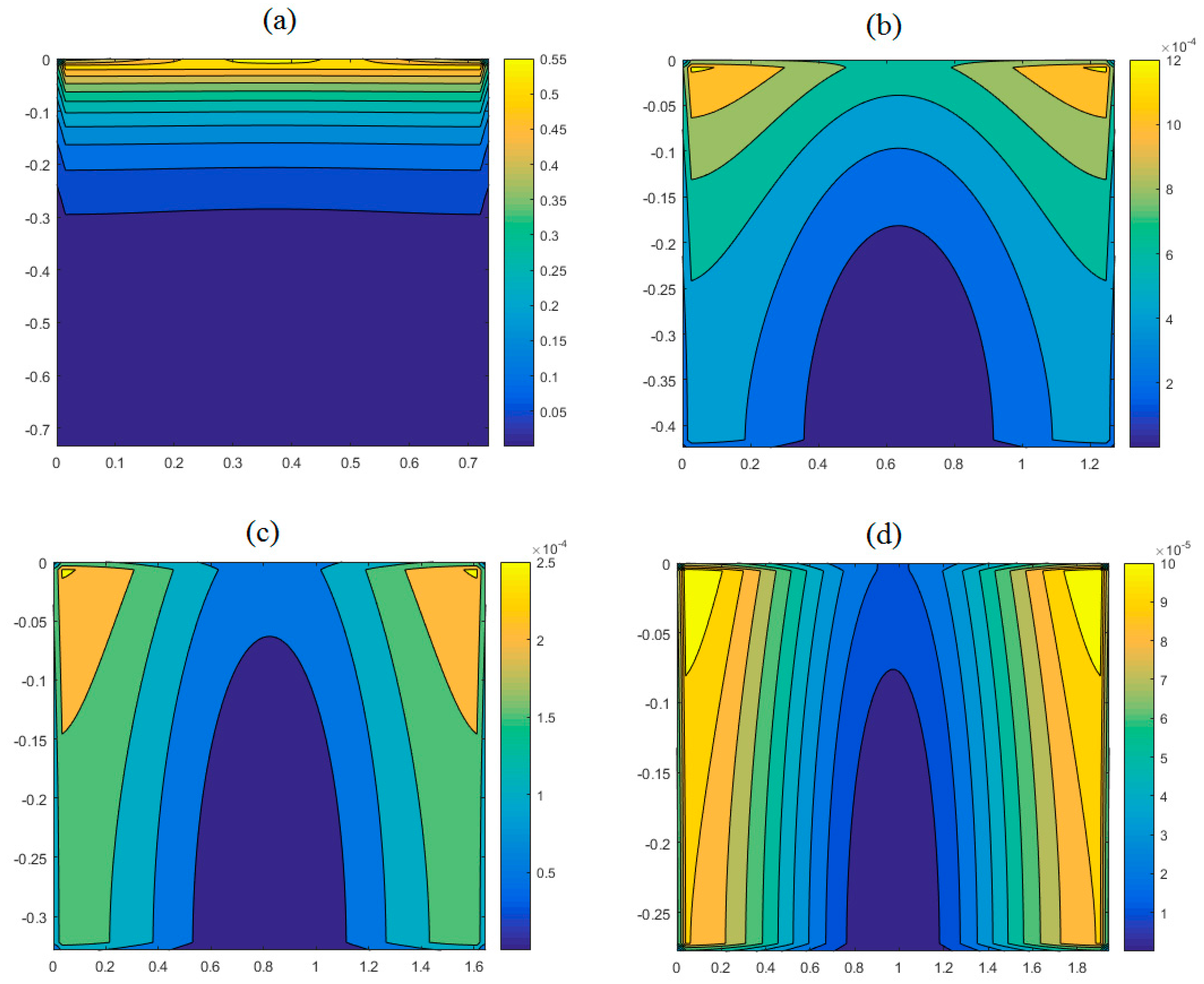
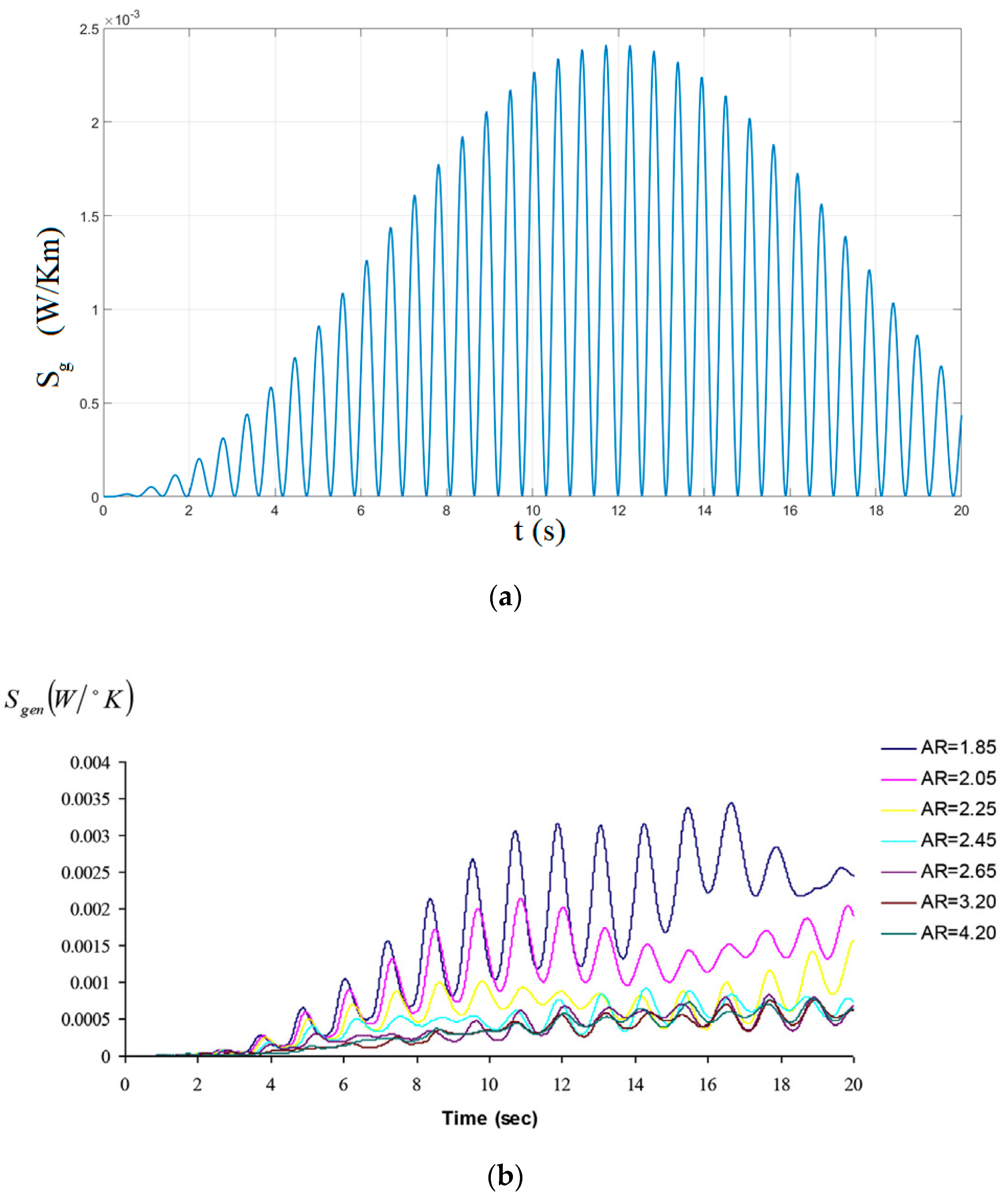
  • By the increase of the aspect ratio, the amount of entropy generated through the volume decreased.
  • By the increase of the aspect ratio, the position of maximum entropy is changed from the free surface to the side walls.
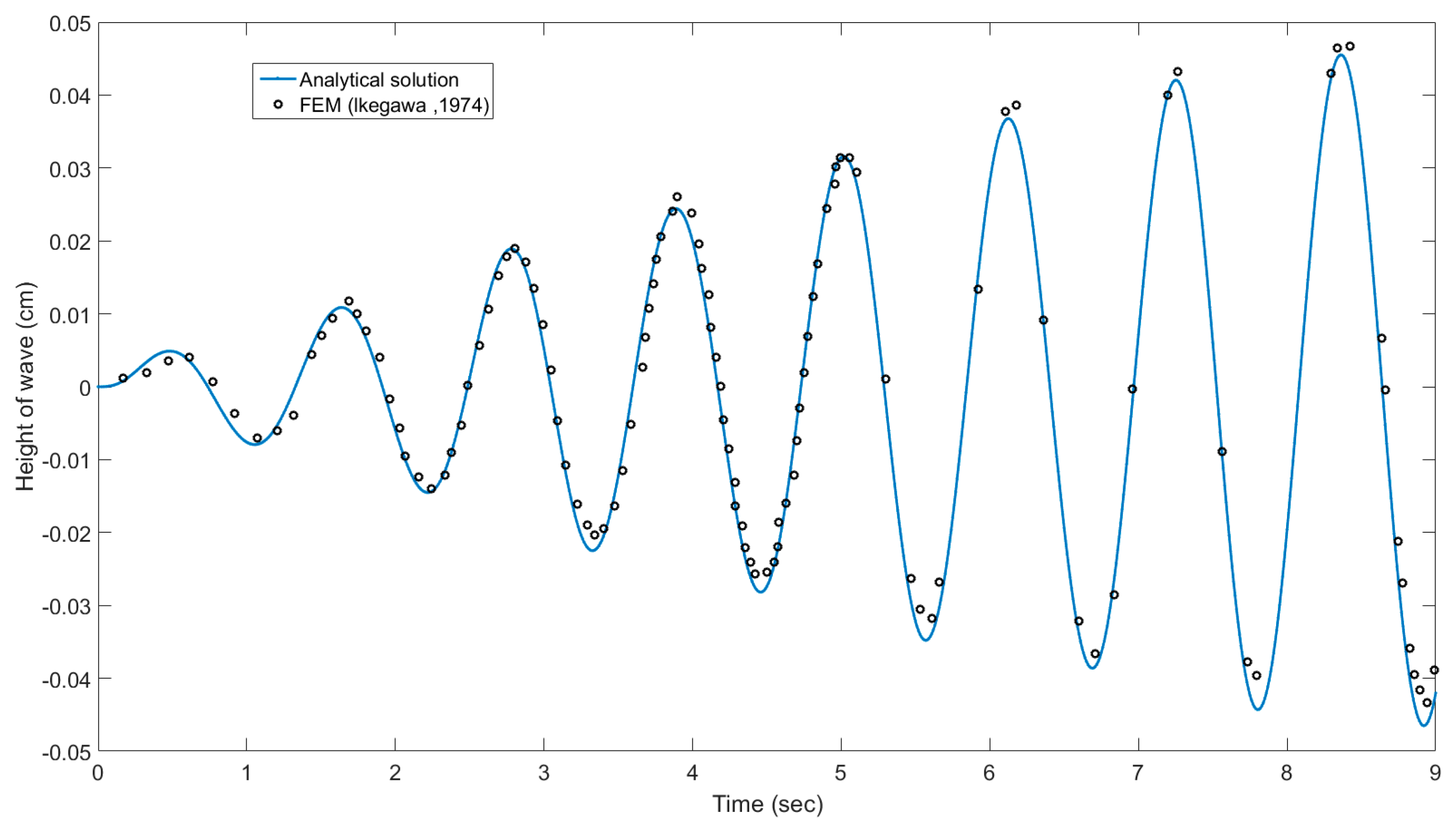
  • As the order of magnitude of the maximum of entropy for the analytical case and numerical results are the same, the analytical solution is a suitable measure for entropy generation minimization.
  • The minimum entropy generation point for the sloshing problem is local and general; the entropy generation has no optimum as a function of aspect ratio.
  • The ratio of structural energy loss to fluid loss is approximated by the ratio of structural mass to fluid mass.
  • The energy dissipation in the structure coupled with sloshing fluids should be considered for entropy generation minimization.
  • The current research proposes to do experiments for coupled cases with total dissipation function (i.e., sum energy dissipation of fluids and structures) as an objective function in future studies.

Funding

This research received no external funding.

Conflicts of Interest

The author declares no conflict of interest.

References

  1. Saghi, H.; Lakzian, E. Optimization of the rectangular storage tanks for the sloshing phenomena based on the entropy generation minimization. Energy 2017, 128, 564–574. [Google Scholar] [CrossRef]
  2. Gholamalizadeh, E.; Jamalabadi, M.Y.A.; Oveisi, M. Optimal design of thermal radiative heating of horizontal thin plates using the entropy generation minimization method. Energies 2017, 10, 1921. [Google Scholar] [CrossRef]
  3. Jamalabadi, M.Y.A.; Safaei, M.R.; Alrashed, A.A.A.A.; Nguyen, T.K.; Filho, E.P.B. Entropy generation in thermal radiative loading of structures with distinct heaters. Entropy 2017, 19, 506. [Google Scholar] [CrossRef]
  4. Jamalabadi, M.Y.A.; Hooshmand, P.; Bagheri, N.; KhakRah, H.; Dousti, M. Numerical simulation of Williamson combined natural and forced convective fluid flow between parallel vertical walls with slip effects and radiative heat transfer in a porous medium. Entropy 2016, 18, 147. [Google Scholar] [CrossRef]
  5. Bejan, A. Entropy Generation Minimization: The Method of Thermodynamic Optimization of Finite-Size Systems and Finite-Time Processes; CRC Press: New York, NY, USA, 1996. [Google Scholar]
  6. Chen, L.; Xia, S.; Sun, F. Entropy generation minimization for isothermal crystallization processes with a generalized mass diffusion law. Int. J. Heat Mass Transf. 2018, 116, 1–8. [Google Scholar] [CrossRef]
  7. Sun, L.M.; Fujino, Y.; Pacheco, B.M.; Chaiseri, P. Modelling of tuned liquid damper (TLD). J. Wind Eng. Ind. Aerody 1992, 43, 1883–1894. [Google Scholar] [CrossRef]
  8. Ibrahim, R.A. Liquid Sloshing Dynamics; Cambridge University Press: Cambridge, UK, 2005. [Google Scholar]
  9. Ikegawa, M. Finite element analysis of fluid motion in a container. In Finite Element Methods in Flow Problems; Oden, J.T., Zienkiewicz, 0.C., Gallagher, R.H., Taylor, C., Eds.; UAH Press: Huntsville, AL, USA, 1974; pp. 737–738. [Google Scholar]
  10. Case, K.; Parkinson, W. Damping of surface waves in an incompressible liquid. J. Fluid Mech. 1957, 2, 172–184. [Google Scholar] [CrossRef]
  11. Jamalabadi, M.Y.A.; Ho-Huu, V.; Nguyen, T.K. Optimal design of circular baffles on sloshing in a rectangular tank horizontally coupled by structure. Water 2018, 10, 1504. [Google Scholar] [CrossRef]
  12. Abramson, H.N. The Dynamic Behavior of Liquids in Moving Containers; National Aeronautics and Space Administration: Washington, DC, USA, 1996. [Google Scholar]
  13. Frandsen, J.B. Sloshing motions in excited tank. J. Comput. Phys. 2004, 106, 53–87. [Google Scholar] [CrossRef]
  14. Chen, B.F.; Nokes, R. Time-independent finite difference analysis of fully nonlinear and viscous fluid sloshing in a rectangular tank. J. Comput. Phys. 2005, 209, 47–81. [Google Scholar] [CrossRef]
  15. Wu, C.H.; Faltinsen, O.M.; Chen, B.F. Numerical study of sloshing liquid in tanks with baffles by time-independent finite difference and fictitious cell method. Comput. Fluids 2012, 63, 9–26. [Google Scholar] [CrossRef]
  16. Huang, S.; Duan, W.Y.; Zhu, X. Time-domain simulation of tank sloshing pressure and experimental validation. J. Hydrodyn. Ser. B 2010, 22, 556–563. [Google Scholar] [CrossRef]
  17. Pirker, S.; Aigner, A.; Wimmer, G. Experimental and numerical investigation of sloshing resonance phenomena in a spring-mounted rectangular tank. Chem. Eng. Sci. 2012, 68, 143–150. [Google Scholar] [CrossRef]
  18. Hasheminejad, S.M.; Aghabeigi, M. Sloshing characteristics in half-full horizontal elliptical tanks with vertical baffles. Appl. Math. Model. 2012, 36, 57–71. [Google Scholar] [CrossRef]
  19. Papaspyrou, S.; Karamanos, S.A.; Valougeorgis, D. Response of half-full horizontal cylinders under transverse excitation. J. Fluids Struct. 2004, 19, 985–1003. [Google Scholar] [CrossRef]
  20. Shekari, M.R.; Khaji, N.; Ahmadi, M.T. A couple BE-FE study for evaluation of seismically isolated cylindrical liquid storage tanks considering fluid–structure interaction. J. Fluids Struct. 2009, 25, 567–585. [Google Scholar] [CrossRef]
  21. Gavrilyuk, I.P.; Lukovsky, I.A.; Timokha, A.N. Linear and nonlinear sloshing in a circular conical tank. Fluid Dyn. Res. 2005, 37, 399–429. [Google Scholar] [CrossRef]
  22. Yue, B.Z. Nonlinear coupling dynamics of liquid filled spherical container in microgravity. Appl. Math. Mech. 2008, 29, 1085–1092. [Google Scholar] [CrossRef]
  23. Sarreshtehdari, A.; Shahmardan, M.M.; Gharaei, R. Numerical simulation and experimental validation of free surface sloshing in a rectangular tank. J. Solid Fluid Mech. 2011, 1, 89–95. [Google Scholar]
  24. Mirzabozorg, H.; Hariri-Ardebili, M.; Nateghi, R. Free surface sloshing effect on dynamic response of rectangular storage tanks. Am. J. Fluid 2012, 2, 23–30. [Google Scholar] [CrossRef]
  25. Rajagounder, R.; Vignesh Mohanasundaram, G.; Kalakkath, P. A study of liquid sloshing in an automotive fuel tank under uniform acceleration. Eng. J. 2015, 20, 72–85. [Google Scholar] [CrossRef]
  26. Ketabdari, M.J.; Saghi, H. Parametric study for optimization of storage tanks considering sloshing phenomenon using coupled BEM-FEM. Appl. Math. Comput. 2013, 224, 123–139. [Google Scholar] [CrossRef]
  27. Bejan, A. A study of entropy generation in fundamental convective heat transfer. J. Heat Transf. 1979, 101, 718–725. [Google Scholar] [CrossRef]
  28. Bejan, A. The thermodynamic design of heat and mass transfer processes and devices. Int. J. Heat Fluid Flow 1987, 8, 258–276. [Google Scholar] [CrossRef]
  29. Lakzian, E.; Masjedi, A. Slip effects on the exergy loss due to irreversible heat transfer in a condensing flow. Int. J. Exergy 2014, 14, 22–37. [Google Scholar] [CrossRef]
  30. Lakzian, E.; Shabani, A. Analytical investigation of coalescence effects on the exergy loss in a spontaneously condensing wet-steam flow. Int. J. Exergy 2015, 4, 383–403. [Google Scholar] [CrossRef]
  31. Lotfi, A.; Lakzian, E. Entropy generation analysis for film boiling: A simple model of quenching. Eur. Phys. J. Plus 2016, 131, 1–10. [Google Scholar] [CrossRef]
  32. Soltanmohammadi, R.; Lakzian, E. Improved design of wells turbine for wave energy conversion using entropy generation. Meccanica 2016, 51, 1713–1722. [Google Scholar] [CrossRef]
  33. Lakzian, E.; Soltanmohammadi, R.; Nazeryan, M. A comparison between entropy generation analysis and first law efficiency in a monoplane wells turbine. Sci. Iran. B 2016, 23, 2673–2681. [Google Scholar]
  34. Wang, T.; Huang, Z.; Xi, G. Entropy generation for mix convection in a square cavity containing a rotating circular cylinder using a local radial basis function method. Int. J. Heat Master Transf. 2017, 106, 1063–1073. [Google Scholar] [CrossRef]
  35. Shadloo, M.S. Numerical Simulation of Compressible Flows by Lattice Boltzmann Method. Numer. Heat Transf. Part A 2019. [Google Scholar] [CrossRef]
  36. Hopp-Hirschler, M.; Shadloo, M.S.; Nieken, U. Viscous Fingering Phenomena in the Early Stage of Polymer Membrane Formation. J. Fluid Mech. 2019, 864, 97–140. [Google Scholar] [CrossRef]
  37. Nguyen, M.Q.; Shadloo, M.S.; Hadjadj, A.; Lebon, B.; Peixinho, J. Perturbation threshold and hysteresis associated with the transition to turbulence in sudden expansion pipe flow. Int. J. Heat Fluid Flow 2019, 76, 187–196. [Google Scholar] [CrossRef]
  38. Shenoy, D.V.; Shadloo, M.S.; Hadjadj, A.; Peixinho, J. Direct numerical simulations of laminar and transitional flows in diverging pipes. Int. J. Numer. Methods Heat Fluid Flow 2019. [Google Scholar] [CrossRef]
  39. Shadloo, M.S.; Weiss, R.; Yildiz, M.; Dalrymple, R.A. Numerical Simulations of the Breaking and Non-breaking Long Waves. Int. J. Offshore Polar Eng. 2015, 25, 1–7. [Google Scholar]
Figure 1. Diagram of fluid-vessel interaction with its cross section.
Mathematics 07 00380 g001
Figure 2. Time history of η (x = + L, t).
Mathematics 07 00380 g002
Figure 3. Distribution of dimensionless entropy generation for various aspect ratios (a) α = 1, (b) α = 3, (c) α = 5, and (d) α = 7.
Mathematics 07 00380 g003
Figure 4. Entropy generation versus time for α = 2.05 (a) current study, (b) Reference [1].
Mathematics 07 00380 g004
Figure 5. Total entropy generation rate versus aspect ratio for α = 3.
Mathematics 07 00380 g005

