1. Introduction
Multi-core processor and many-core processor have become dominant processor models in many modern computer systems including smartphones, tablet PCs, desktop computers and even high-performance server systems [
1,
2]. Modern high-performance processors comprise two or more independent cores, and each core can be connected to various interconnection network topologies, such as bus, ring, mesh, and crossbar. Whereas the performance of a single core is limited by physical constraints, recent technological advances have made processors with many cores feasible [
3,
4]. The parallelism provided by multi- or many-core processors gives greater cost-performance benefits over single-core processors.
To maximize the performance of these multi-core processors, it is important to support efficient data communication among cores. Data communications among processors are undertaken by using point-to-point and collective communications. Point-to-point communication is used when there is a single sender and a single receiver, and it is relatively easy to implement efficiently. Collective communication is for multiple senders and/or receivers, and it is difficult to implement efficiently because the topology-aware implementation is required for good performance [
5]. To ensure implementation efficiency, collective communications are generally converted into groups of point-to-point communication [
6]. Common collective communication patterns are broadcast, scatter, gather, all-gather, all-to-all, reduce, all-reduce, and so on [
7,
8].
Collective communication operations are generated through the use of programming that uses multiprocessing libraries, such as OpenMP, message passing interface (MPI), or compute unified device architecture (CUDA). Generally, using collective communication operations reduces the code size and also increases performance, compared to using point-to-point communication operations. Moreover, collective communication operations account for approximately up to 80% of the total data transmission time; therefore, it is very important to improve their execution time [
9,
10,
11].
Broadcasting is a frequently used form of collective communications; it is used to disseminate data messages in the root node (core) to all the other nodes (core) that belong to the same communicator. Following the advent of the sequential tree algorithm [
12], various broadcast algorithms have been proposed; these include the binary tree, binomial tree [
13], minimum spanning tree, and distance minimum spanning tree algorithms, as well as Van de Gejin’s hybrid broadcast [
14] and modified hybrid broadcast [
15] algorithms. These algorithms offer performance efficiency by tuning network topologies in collective communications.
Since then, pipelined broadcast algorithms have been proposed to accelerate the processing time of broadcast communication at the operating system level [
9,
16], by utilizing the maximum bandwidth. There have also been a few diverse works on pipelined broadcast algorithms [
17,
18,
19,
20,
21] that look to improve the processing time of broadcast communication. In the pipelined broadcast algorithm, data are packetized into
k partitions to make
k-pipeline stages, so that it activates most communication ports efficiently. However, the action of packetizing incurs
k-1 number of additional synchronization processes. As a result, the pipelined broadcast algorithm has an inherent limitation in improving the performance of broadcast communication because it improves the data transmission time but incurs an unnecessary synchronization time-cost.
First, this paper explains an enhanced algorithm for pipelined broadcasting; it is called an “atomic pipelined broadcast algorithm” [
22]. In this preliminary study, the enhanced algorithm accelerates the processing time of broadcast communication by drastically reducing the number of synchronization processes in the conventional pipeline broadcast algorithm. This reduced number of synchronization processes is accomplished by developing a light-weight protocol and employing simple hardware logic, so that the message broadcast can be performed in an atomic fashion with full pipeline utilization.
Additionally, this paper proposes an inter-node transmission order change technique considering the communication status of processing nodes. The reinforcement learning algorithms have been already adopted in various transmission orders or selection problems in 5G networks [
23,
24]. However, these pre-existing algorithms could not be applied to on-chip communications because they have too high of an implementation complexity supported by software to be implemented to hardware logic. For on-chip communications, the proposed method has appropriate complexity and efficient performance. The proposed method changes the transmission order for the broadcast operation based on the communication status of processing nodes. When a broadcast operation is received, a local bus checks the remaining pre-existing transmission data size of each processing node; it then transmits data according to the changed transmission order using the status information. Therefore, the synchronization time can be hidden for the remaining time, until the pre-existing data transmissions finish; as a result, the overall broadcast completion time is reduced.
To validate this approach, the proposed broadcast algorithm is implemented to a bus functional model (BFM) with SystemC, and then evaluated in the simulations from using various communication data sizes and numbers of nodes. The simulation results indicate that the speed-up ratio of the atomic pipelined broadcast algorithm is up to 4.113, compared to that of the previous pipelined broadcast algorithm, which lacks any changes to the transmission order, when a 64-byte date message is broadcasted among 32 nodes.
In order to demonstrate physical implementation feasibility, the message passing engine (MPE) supporting the proposed atomic broadcast algorithm and the enhanced transmission order change technique was designed by using Verilog-HDL, which comprises four processing nodes. The logic synthesis results with TSMC 0.18 μm process cell libraries show that the logic area of the proposed MPE was 2288.1 equivalent NAND gates, which represents approximately 2.1% of the entire chip area. Therefore, performance improvement is expected with a small hardware area overhead, if the proposed MPE were to be added to multi-core processors.
The remainder of this paper is organized as follows.
Section 2 introduces trends in the interconnection networks of multi-core processors, as well as the previous algorithms that served as the motivation for the thinking behind this paper.
Section 3 explains the proposed atomic pipelined broadcast algorithm with the inter-node transmission order change technique.
Section 4 provides the simulation results, and a discussion thereof.
Section 5 details the modified MPE implementation and synthesis results, and
Section 6 provides concluding remarks.
2. Background Research
2.1. Interconnection Networks on Multi-Core Processors
An interconnection network in multi-core processors transfers information from any source core to any desired destination core. This transfer should be completed with as small latency as possible. It should allow a large number of such transfers to take place concurrently. Moreover, it should be inexpensive as compared to the cost of the rest of the machine. The network consists of links and switches, which help to send the information from the source core to the destination core. The network is specified by its topology, routing algorithm, switching strategy, and flow control mechanism.
The leading companies in multi-core processors have developed their own interconnection network architectures for data communication among cores. Intel has developed two processor types: general-purpose processors such as those in the I7 series, and high-performance computing processors such as the Xeon Phi processor. In Intel’s general-purpose processors, a crossbar is used for interconnection among cores, and quick-path interconnection (QPI) is used for interconnection among processors [
25,
26].
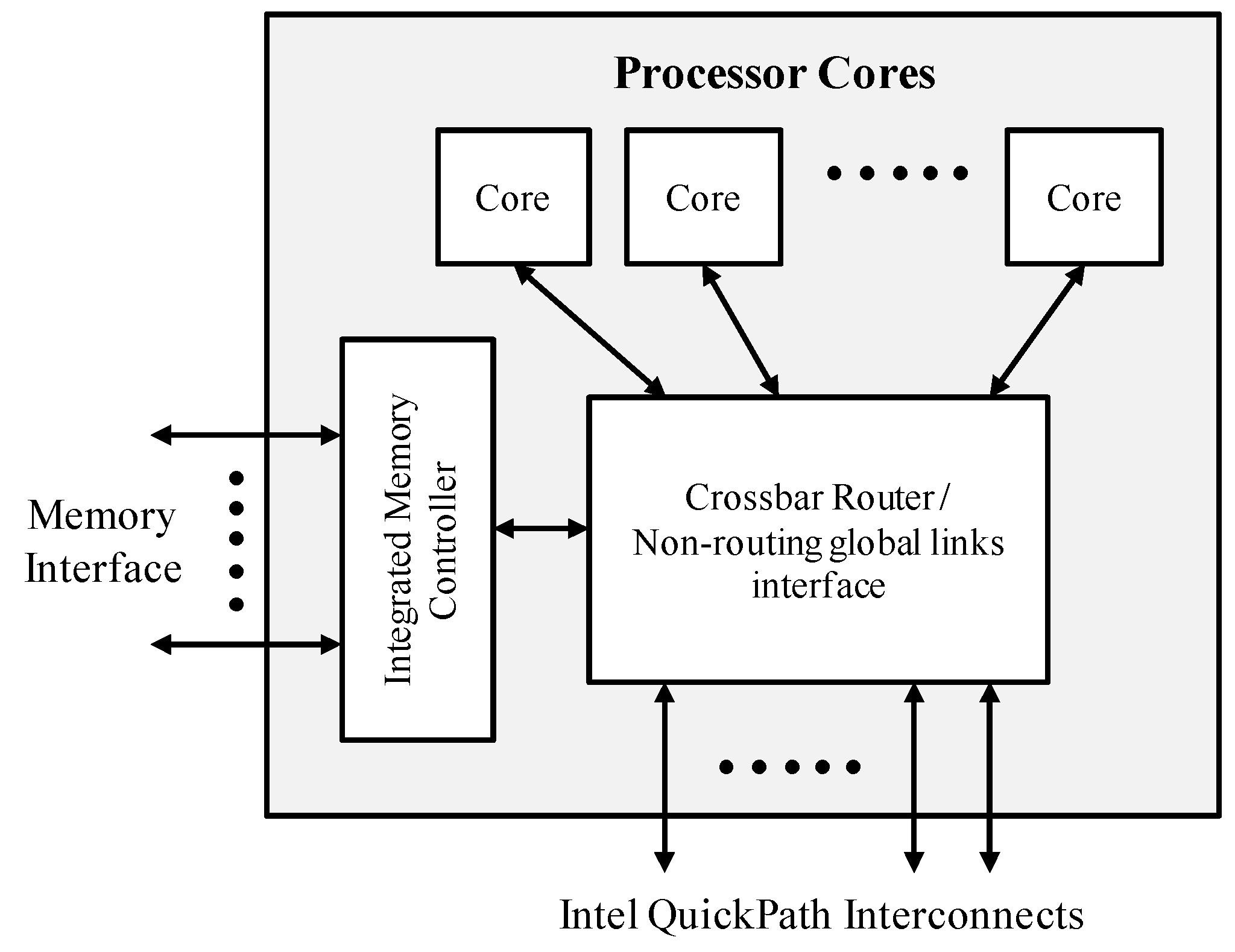
Figure 1 is a block diagram of a multi-core processor with external QPI. The processor has one or more cores, and it also typically comprises one or more integrated memory controllers. The QPI is a high-speed point-to-point interconnection network. Although it is sometimes classified as a type of a serial bus, it is more accurately considered a point-to-point link, as data are sent in parallel across multiple lanes and its packets are broken into multiple parallel transfers. It is a contemporary design that uses some techniques similar to those seen in other point-to-point interconnections, such as peripheral component interconnect express (PCIe) and a fully-buffered dual in-line memory module (FB-DIMM). The physical connectivity of each link consists of 20 differential signal pairs and a differential forwarded clock. Each port supports a link pair consisting of two uni-directional links that connect two processors; this supports traffic in both directions, simultaneously [
27]. Additionally, the QPI comprises a cache coherency protocol to maintain the distributed memory and caches coherent during system operation [
28].
The up-to-date Intel Xeon Phi processor, codenamed “Knight Landing” (KNL), comprises 36 processor tiles, where each processor tile consists of two cores, two vector processing units (VPU), and 1 MByte L2. All processor tiles are interconnected to 2D mesh interconnection, and the interconnection among Xeon Phi processors is an Intel omni-path fabric interconnection [
29,
30,
31].
Figure 2 is a block diagram of an Intel Xeon Phi Processor with omni-path fabric interconnection. The omni-path fabric is connected through the two x16 lanes of PCI express to the KNL die, and it provides two 100-Gbits-per-second ports, out of the package [
32].
AMD also uses a crossbar to interconnect cores and the interconnection among processors is HyperTransport, which is a high-speed point-to-point interconnection network similar to Intel QPI [
33,
34].
Figure 3 is a block diagram of an AMD processor with HyperTransport interconnection, which provides scalability, high bandwidth, and low latency. The distributed shared-memory architecture includes four integrated memory controllers (i.e., one per chip), giving it four-fold greater memory bandwidth and capacity compared to traditional architectures without the use of costly power-consuming memory buffers [
35].
ARM is a leading embedded system-on-a-chip (SoC) technology, with its ARM multi-core processors and advanced microcontroller bus architecture (AMBA) intellectual properties (IPs). Since AMBA was first introduced in 1996, it has described a number of buses and interfaces for on-chip communications. The first version of AMBA contained only two buses: the advanced system bus (ASB) and the advanced peripheral bus (APB). However, the current version adds a wide collection of high-performance buses and interfaces, including the advanced high-performance bus (AHB), the advanced extensible interface (AXI), and AXI coherency extensions (ACE) [
36]. Since AMBA bus protocols are today the de facto standard for embedded processors and can be used without royalties, the AMBA bus has been widely used in high-performance multi-core processor SoC designs [
37,
38,
39]. In up-to-date multi-core processors for mobile applications such as the Samsung Exynos Octa 9820 [
39] and the Qualcomm Snapdragon 855 [
40], multiple cores are interconnected via the AMBA bus. Additionally, in 2012, the chip implementation of a multi-core processor, in which 32 cores are interconnected via the AMBA bus, was presented [
41].
2.2. Pipelined Broadcast
Various broadcast algorithms have been proposed, including the binary tree, binomial tree, minimum spanning tree, and distance minimum spanning tree algorithms, as well as Van de Gejin’s hybrid broadcast and modified hybrid broadcast algorithms. These algorithms offer performance efficiency by tuning network topologies in collective communications [
12].
Since then, pipelined broadcast algorithms have been proposed to accelerate the processing time of broadcast communication by utilizing the maximum bandwidth [
9,
16]. A few diverse works on pipelined broadcast algorithms [
17,
18,
19,
20,
21] have considered the means of improving the processing time of broadcast communication.
In the pipelined broadcast algorithm, data to be broadcast are partitioned into
k packets as shown in
Figure 4, and the packets are transmitted through a
k-step pipeline as in
Figure 2,
Figure 3,
Figure 4 and
Figure 5; this means the communication channels can be heavily used during the period from step 3 to throughout step
k with iterative synchronization processes, which is unavoidable on the mesh network level to verify the next destination. Consequently, the algorithm shows better performance as the data size increases. Thus, the value of
k is very important in balancing the trade-offs between the number of synchronization processes and the utilization of the communication channels. The value of
k is known to be optimal if it is chosen according to Equation (1) [
16].
;
;
.
In the pipelined broadcast algorithm shown in
Figure 5, we could see that
k-iterative synchronization processes were needed in each pipeline step. Suppose that the number of cycles required for synchronization in one pipeline step is m cycles, and that the operating frequency is f MHz; then, the total synchronization time will be calculated as in Equation (2). This will incur an O(
k) arithmetic cost, leading to inefficient channel throughput due to diminishing return as
k increases.
In the case of broadcast communication, all data messages should be transferred to every node within the communicator, as soon as possible. As it is common to simultaneously allocate all channels to broadcast data, the recommended scenario is to have the host node preempt all pipeline channels and broadcast the data in the form of nonblocking chain operations, making all pipeline channels fully utilized.
3. Atomic Pipelined Broadcast with Inter-Node Transmission Order Change
3.1. Atomic Pipelined Broadcast
As a preliminary study, the author presented the enhanced algorithm to overcome the disadvantage of pipelined broadcasting, which is called an atomic pipelined broadcast algorithm [
22]. The term “Atomic” derives from the concept of an atomic transaction, where a transaction should be performed either in its entirety or not at all [
42]. This algorithm accelerates the processing time of broadcast communication by drastically reducing the number of synchronization processes involved. This reduction was accomplished by developing a light-weight protocol and employing simple hardware logic, so that the data message broadcast can be performed in an atomic fashion with full pipeline utilization. This section explains the details of the atomic pipelined broadcast and discusses the resulting performance improvement.
In the conventional pipelined broadcast algorithm described in
Section 2.2, each processing node plays one of three roles: head, body or tail. For example, as shown in
Figure 5, PN0 is a head node, PN1 and PN2 are body nodes, and PN3 is a tail node. In the case of the head node, PN0 sends data toward PN1, where the broadcast communication is converted into
k point-to-point send operations. In the case of PN3, which is a tail node, the broadcast communication is converted into
k point-to-point receive operations. On the other hand, the body nodes such as PN1 and PN2 receive data from one node and simultaneously send the data to another, where the broadcast communication converts into
k point-to-point send operations and also
k receive operations. At this point,
k times as many as iterative synchronization processes occur, which we want to avoid if there is no need to synchronize in between the initiation and the completion of the broadcast procedure.
One way to avoid these iterative synchronization processes is by having solid network connections among all the processing nodes, which can be naturally found in a multi-core processor’s bus structure such as an AMBA bus. Using this bus structure, we could preempt all the communication channels by establishing specific protocols, and use the pipeline seamlessly as shown in
Figure 6.
In order to realize the seamless atomic transfer, the compiler should not convert the broadcast routine into multiple point-to-point communications. Instead, a new method is required that is capable of storing the packetized data words from one node into buffers without synchronization, and simultaneously forward them to another. Thus, we proposed a new supplementary operation, which we called Fwd, so that the broadcast routine could be converted into Send, Recv, and Fwd for the head, tail, and body nodes, respectively.
To support the atomic pipelined broadcast, a communication bus conforms to a cross-bar structure, through which all processing nodes can send and receive data. All processing nodes can be head, body, or tail nodes according to the broadcast routine. The role of the body nodes among them is very important because it stores the packetized data words from one node into buffers without synchronization and simultaneously forwards them to another.
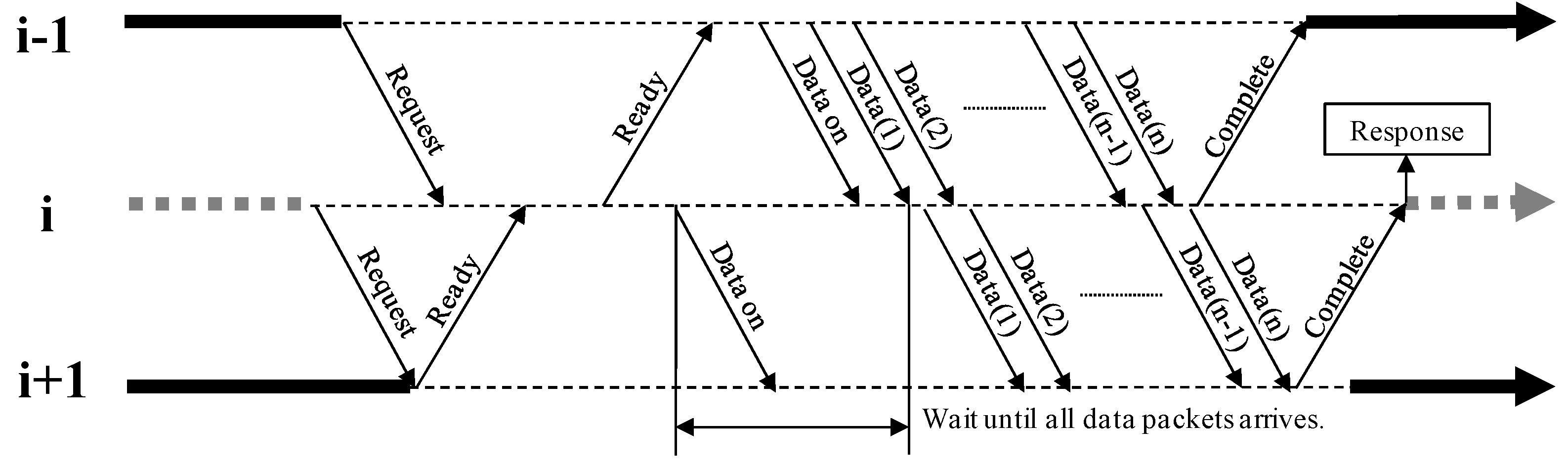
A Fwd operation should follow the order shown in
Figure 7; this order applies to all body nodes. If the order is not followed, the process should enter a state of a deadlock. This is treated as a non-interruptible atomic transmission, to ensure both full channel utilization and reliability. The procedure is as follows:
Send request message to i + 1 node.
Recv request message from i – 1 node.
Recv ready message from i + 1 node.
Send ready message to i – 1 node.
Recv and Send data messages between adjacent nodes.
Recv and Send complete messages between adjacent nodes.
3.2. Inter-Node Transmission Order Change Technique
3.2.1. Initial Idea of Transmission Order Change Technique
To maximize broadcast communication performance, this paper proposed the concept of changing the transmission order. First, the author designed the model of the initial idea, which could begin the communication faster by reducing the amount of time that passes until the pre-existing message transmissions in all processing nodes finish. Since the barrier function for communication synchronization is always performed before the broadcast communication, none of the previous broadcast algorithms can begin the broadcast communication until all the communication ports of the processing nodes are free.
Basically, the transmission order should be pre-defined in all broadcast algorithms regardless of the transmission order change technique being used; this is because the pre-defined order is used as a reference when the transmission order is determined. Before the transmission order change technique is presented, the broadcasting algorithms transmit data messages in the pre-defined order. The transmission order change technique requires a hardware logic to change the transmission order, and so it references the pre-defined order to determine the order in the same processing node group and the free and busy groups. In this paper, the pre-defined transmission order followed the numeric order, according to the processing node names: P0→P1→P2→P3→···→Pn.
Figure 8 shows the transmission orders in the atomic pipelined broadcast algorithm without the transmission order change technique when P1–P4 have the existing ongoing transmissions. As shown in the figure, when performing broadcast communication in the situation with the pre-existing transmissions, a waiting time of three cycles is required, because the root P0 should wait until all the existing ongoing transmissions of P1–P4 finish.
Figure 9 shows the transmission orders in the atomic pipelined broadcast algorithm with the initial transmission order change technique when P1–P4 have the existing ongoing transmissions. All processing nodes are sorted into the “free” or “busy” group, and the transmission order is determined in each group as per the pre-defined numeric order. Additionally, the free group is always in front of the busy group. In this way, the transmission order is changed to P0→P5→P6→P7→P1→P2→P3→P4, and the root P0 can begin the broadcast communication without waiting three cycles occurred in the case of
Figure 8.
3.2.2. Enhancing Transmission Order Change Technique
This section presents the inter-node transmission order change technique used to derive performance better than that seen with the initial technique. As described in
Section 3.2.1, only applying the initial transmission order change technique to the atomic pipelined broadcast algorithm will improve the broadcast performance. This is expected, as the atomic pipelined broadcast improves the execution time of broadcast communication itself by reducing the number of synchronization; however, the transmission order change technique reduces the waiting time that occurs before the broadcast communication begins.
To achieve better performance improvement, one should be aware of the limitation of the initial transmission order change technique.
Figure 10 shows the waiting time in the atomic pipelined broadcast without the transmission order change technique, when P1’s pre-existing transmission data size increases. Since P1’s pre-existing data transmission finishes at Cycle 6, the root P0 should wait until then.
Figure 11 shows the waiting time in the atomic pipelined broadcast with the initial transmission order change technique, when P1’s pre-existing transmission data size becomes larger. The P7→P1→P2 data transmission of P1 is delayed by two cycles, due to its pre-existing data transmission. Broadcast communications undertakes the synchronization before data transmissions; synchronization is a process to check if the communication ports of all processing nodes are available for broadcast communication. As described in
Section 2.2, the pipelined broadcast algorithm is synchronized by propagating the request message from P0 (a head node) to the last processing node (a tail node), and the ready message from a tail to a head. In the figure, P1 receives the ready message at Cycle 4, but it remains in a buffer until the earlier messages are transmitted. Finally, P1 performs the ready message at Cycle 6; which means that the effective beginning cycle of broadcast communication is Cycle 2, even though it begins at Cycle 0.
The inter-node transmission order change technique is proposed, to overcome this limitation inherent in the initial technique. In the proposed technique, a multi-core processor system sorts each of the processing nodes into the “free” or “busy” group, just as seen in the initial technique. However, it determines the transmission orders only in the free group as the pre-defined numeric order. For the busy group, it changes the transmission order according to the remaining pre-existing transmission data size. Then, it calculates the waiting time by using the processing nodes’ remaining pre-existing transmission data size. Therefore, the additional hardware logic for the proposed technique should be added to the multi-core processor systems, but its hardware overhead can be ignored as the logic area of the message passing engine in multi-core processors is very much smaller than that of processors. It was only 1.94% in the initial transmission order change technique.
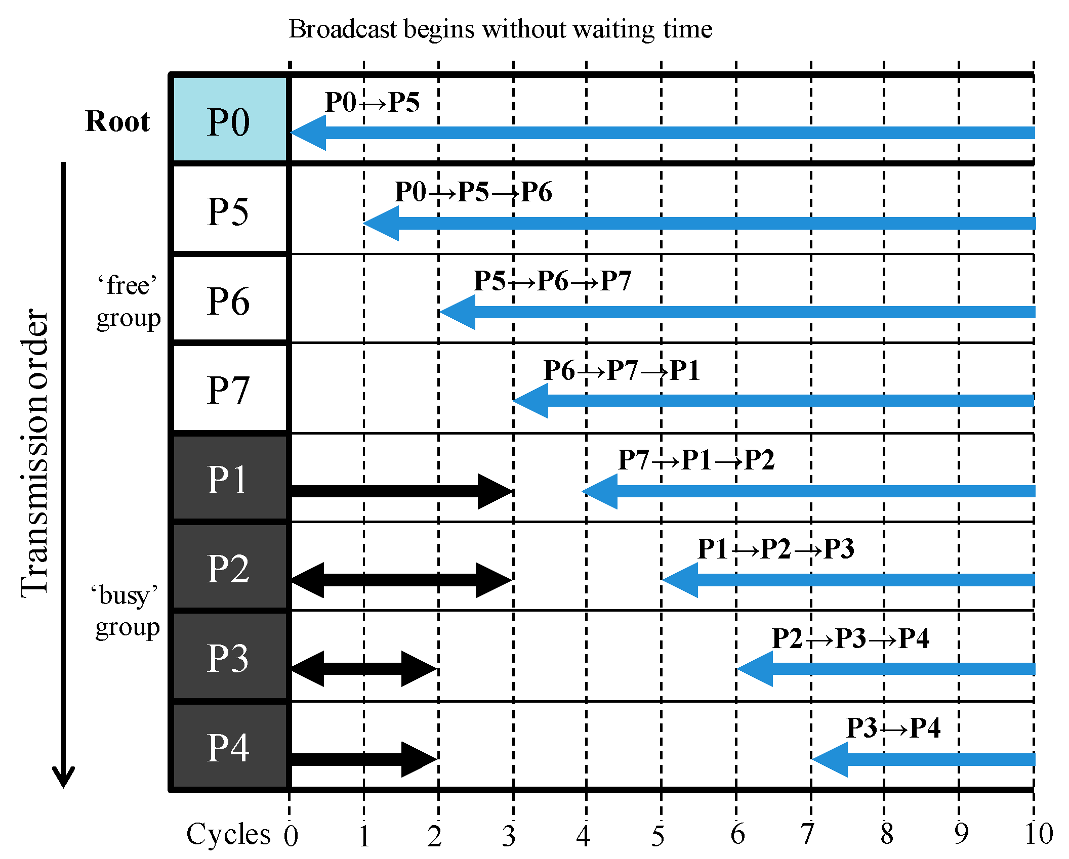
Figure 12 shows the reduced waiting time in the atomic pipelined broadcast with the proposed inter-node transmission order change technique, when P1’s pre-existing transmission data size becomes larger. Since the proposed technique does not change the transmission order in the free group, the transmission order is P0→P5→P6→P7, as seen with the initial technique. In the busy group, P1, P2, and P3 and P4 have the existing data transmissions for six, three, and two cycles, respectively. According to the order in the remaining pre-existing transmission data size, the transmission order is changed to P3→P4→P2→P1. Consequently, the final transmission order is P0→P5→P6→P7→P3→P4→P2→P1.
As shown in the figure, the broadcast communication begins at Cycle 0; in this respect, it is identical to the case adopting the initial transmission order change technique; however, the broadcast communication’s effective beginning cycle also is Cycle 0. If P1’s pre-existing transmission data size becomes larger, the performance improvement will also increase.
3.2.3. Analysis of Minimizing Waiting Time with Inter-Node Transmission Order Change Technique
Figure 13 and
Figure 14 show the transmission orders in the atomic pipelined broadcasts without and with the inter-node transmission order change technique, respectively, when P1 has the pre-existing data transmission. In
Figure 13, the root P0 should wait for eight cycles until P1’s pre-existing data transmission finishes, because it cannot change the transmission order.
However, as shown in
Figure 14, the atomic pipelined broadcast with the proposed inter-node transmission order change technique waits for only one cycle by virtue of the changed transmission order, because it can handle the transmission order according to the processing nodes’ remaining pre-existing transmission data size.
3.2.4. Process Sequence of Inter-Node Transmission Order Change Technique
To support these transmission order techniques, the local bus requires a status register. In the initial transmission order change technique, this was 8 bits in total (i.e., 1 bit for each processing node). To support the proposed inter-node transmission order change technique, this was increased to 2 bits for each processing node, to identify the pre-existing transmission data size. The 2-bit value means that “00” was the “free” status and “01”, “10”, and “11” are “busy” with a remaining transmission data size of under 512 bytes, under 1024 bytes, and over 1024 bytes, respectively. If the size of the status register for each processing node was increased from 2 bits to 3 bits or more, it would be possible to classify the communication status of processing nodes at a finer granularity.
Figure 15 briefly shows the process sequence of the inter-node transmission order change technique, when the root node receives the broadcast operation. Detailed information is provided in
Section 3.3. In this figure, the message passing engine (MPE) of the root P5 orders the local bus to distribute the value of the status register to all the MPEs. The status register had 2 bits for each processing node: 16 bits in total. In the initial transmission order change technique, this was 8 bits in total (i.e., 1 bit for each processing node). To support the proposed transmission order change technique, the size of the status register was increased to identify the pre-existing transmission data size. In Step ③ of
Figure 15, the local bus distributes the status register value to all MPEs. The MPE arranges the processing nodes’ physical numbers in order, by the 2-bit value for each MPE. In this figure, the status register value was assumed to “10 10 10 11 10 00 01 01”; therefore, the processing nodes’ physical numbers were arranged into P5→P6→P7→P0→P1→P2→P4→P3. Then, the intermediate control message was generated by using the information of the sequential tree read-only memory (ROM) and physical/logical (P/L). The intermediate control message was translated to the final control message, and it was then stored in the issue queue.
3.3. Modified Message Passing Engine Architecture
Generally, multi-core processors do not have an MPE that can handle collective communication; therefore, compilers may convert collective communication operations into a group of point-to-point operations. However, multi-core processors with an MPE that can handle them can send the collective communication operations to the processing node, without converting them into point-to-point operations [
43,
44,
45,
46,
47,
48]. Then, they are performed in the MPE of processing nodes, according to the function and feature of each MPE.
To support the atomic pipelined broadcast and the inter-node transmission change order technique, the previous MPE architecture also should be modified. The modified MPE can receive three types of incoming operations, which are Send, Recv, and Bcast. Send and Recv messages are stored directly in the issue queue and then the communication begins. The broadcast operation is converted into point-to-point operations by the atomic broadcast algorithm, and then the converted operations are stored in the issue queue.
Figure 16 is the flow chart for processing the incoming command messages in the modified MPE. In the case of the broadcast, the root node orders the local bus to distribute the value of the status register to all the processing nodes in the communicator. After the statuses of the processing nodes are checked, the MPE reads the pre-defined transmission order from the ROM, translates the logical node number into the physical node number, and then determines the transmission order. According to the order, the MPE generates the control messages, which consist of Send, Recv, and Fwd and store them in the issue queue.
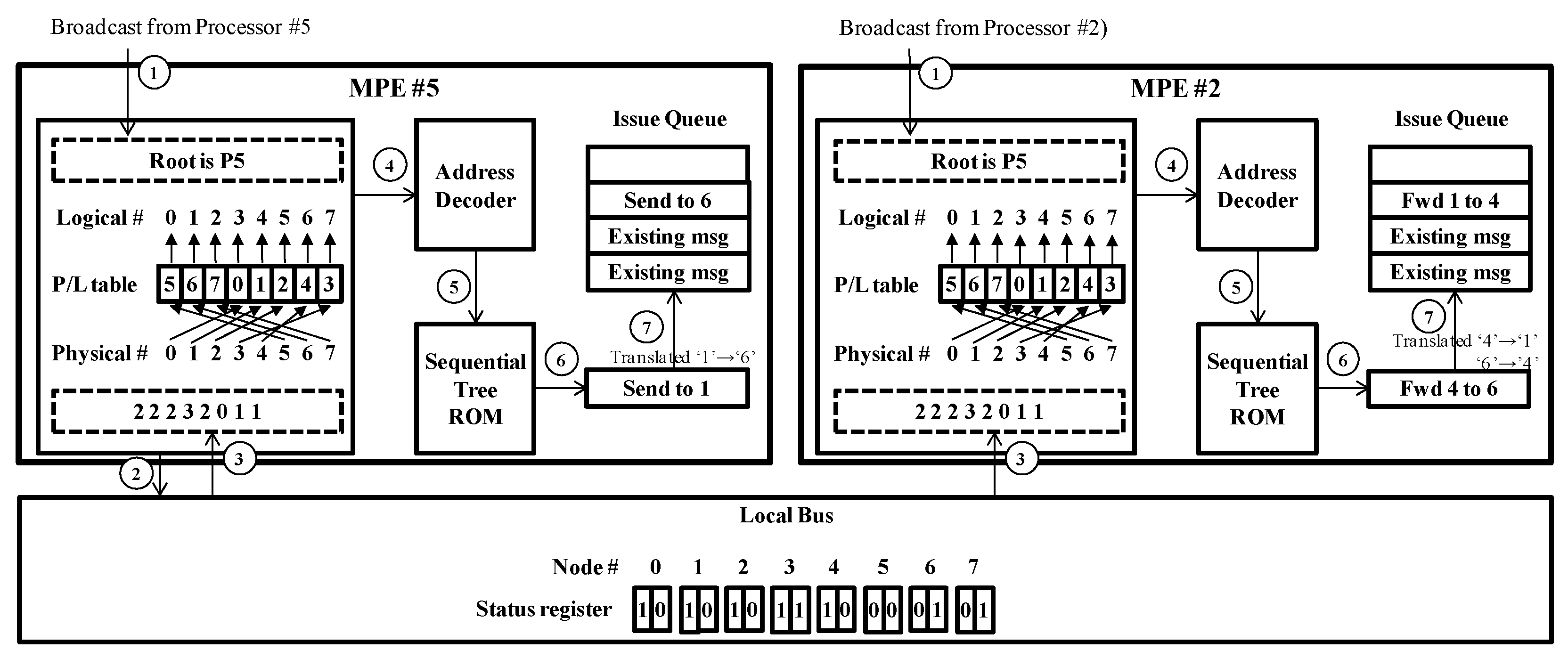
Figure 17 shows the process sequence for the broadcast command in the modified MPE when the communicator has eight processing nodes. In this figure, the case of MPE #5 (left side) is the process sequence for the root node; the right side is for the leaf node. The process sequence is as follows.
① All MPEs receive the broadcast command from their own cores. The command indicates the root node; in this case, the root is P5. Therefore, all MPEs know the node number.
② The root MPE orders the local bus to distribute the value of the status register to all MPEs. The status register has 2 bits for each MPE; it is 16 bits in total. In the initial transmission order change technique, it is 8 bit in total (i.e., 1 bit for each MPE). To support the inter-node transmission order change technique, this is increased to identify the pre-existing transmission data size. The 2-bit value for each MPE means that “00” is “free” status, and “01”, “10”, and “11” are “busy” with a remaining transmission data size of under 512 bytes, under 1024 bytes, and over 1024 bytes, respectively. In leaf nodes, this step is ignored.
③ The local bus distributes the status register value to all the MPEs. The MPE arranges the nodes’ physical numbers, in the order of the 2-bit value for each MPE. If any 2-bit values are identical, they are arranged in numerical order. In this figure, the status register value is “10 10 10 11 10 00 01 01”; therefore, the nodes’ physical numbers are arranged into P5→P6→P7→P0→P1→P2→P4→P3. Then, the MPE writes the information pertaining to the arranged nodes’ physical numbers in the physical-to-logical number map table (P/L table).
④ and ⑤ The address decoder generates and provides the physical address corresponding to each logical address, according to the P/L table. This step is needed because the sequential tree ROM has the information pertaining to the pre-defined transmission order based on the logical address. Therefore, to change the transmission order, the corresponding physical addresses are required.
⑥ The intermediate control message is generated. The sequential tree ROM has the information pertaining to the pre-defined transmission order based on the logical address; this is P0→P1→P2→P3→P4→P5→P6→P7. In the root MPE #5, the physical address is “5”, and the corresponding logical address is “0”. Therefore, MPE #5 generates the intermediate control message for P0→P1 (Send to 1). In the leaf MPE #2, the intermediate control message for P4→P5→P6 (Fwd 4–6) is generated because the logical address is “5”.
⑦ The intermediate control message is translated into the final control message, and it is then stored in the issue queue. In MPE #5, the intermediate control message is “Send to 1”; it is translated into “Send to 6” because the physical address for the logical address “1” is “6”. In this way, in MPE #2, the intermediate control message “Fwd 4 to 6” is translated into “Fwd 1 to 4”. Then, the translated control message is stored in the issue queue.
4. Simulation Results and Discussion
This section discussed the performance improvements offered by the atomic pipelined broadcast algorithm with the inter-node transmission order change technique, along with the simulation results. The simulation was performed with the multi-core processor system and the bus functional models that support each broadcast algorithm. The total communication time for data message broadcasting among multiple cores in the system was also measured and compared.
As described previously, the atomic pipelined broadcast was developed to reduce the execution delay of the broadcast communication. In addition, the proposed inter-node transmission order change technique was proposed to reduce the waiting time. In order to evaluate performance improvement in terms of both execution time and waiting time, seven broadcast algorithms were implemented and compared in this section.
To explore the multi-core processor system architectures, the system architecture and the bus functional models (BFMs) were modeled with SystemC while considering the latencies of the functional blocks. They generated communication traffics in each specific simulation environment. To simplify the simulation, the operating clock frequency of this system was defined as 100 MHz. AMBA bus protocol can support 32 processors without the increase of clock cycles to transceiver data. As more processors are connected to the bus system, the hardware complexity of the bus system block also increases. The increased hardware complexity can make the timing closure worse in register-transfer level to graphic database system (RTL-to-GDS) application specific integrated circuit (ASIC) design flow. However, the sign-off timing closure for the bus system block in the commercial SoCs such as Samsung Exinos and Qualcomm Snapdragon was finished with about three times slower clock frequency than that of CPU. The three times slower clock frequency was enough to support 32 processors in AMBA. The bus bandwidth could transmit 4 bytes per clock cycle. All processing nodes in the system were interconnected with each other via a crossbar bus.
The broadcast communication performance of the broadcast algorithms was evaluated by simulating communication traffics with their own BFM. The execution time was measured as the variation in the data message size from 4 to 2048 bytes, when the number of processing nodes was 4, 8, 16, or 32. The simulation environment was based on the circumstances as described in
Table 1.
The simulations describe the performance improvements in terms of reducing the waiting time before broadcast communication begins. In any broadcast communication without the pre-existing data transmission, the transmission order change technique was unnecessary, because the changed transmission order would be identical to the pre-defined order; therefore, to evaluate the performance of the transmission order change technique, the simulation environment was carefully prepared. Then, the simulations were performed to compare the atomic pipelined broadcast algorithm with the proposed transmission order change technique (APOC) and the atomic pipelined broadcast algorithm without the technique (AP).
Figure 18,
Figure 19,
Figure 20 and
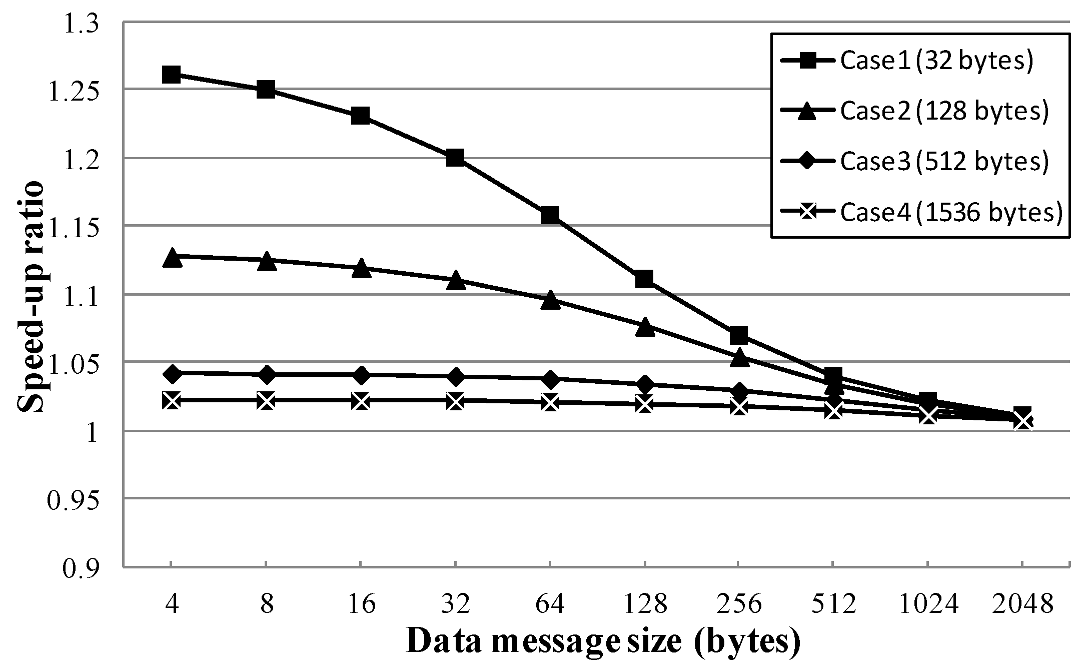
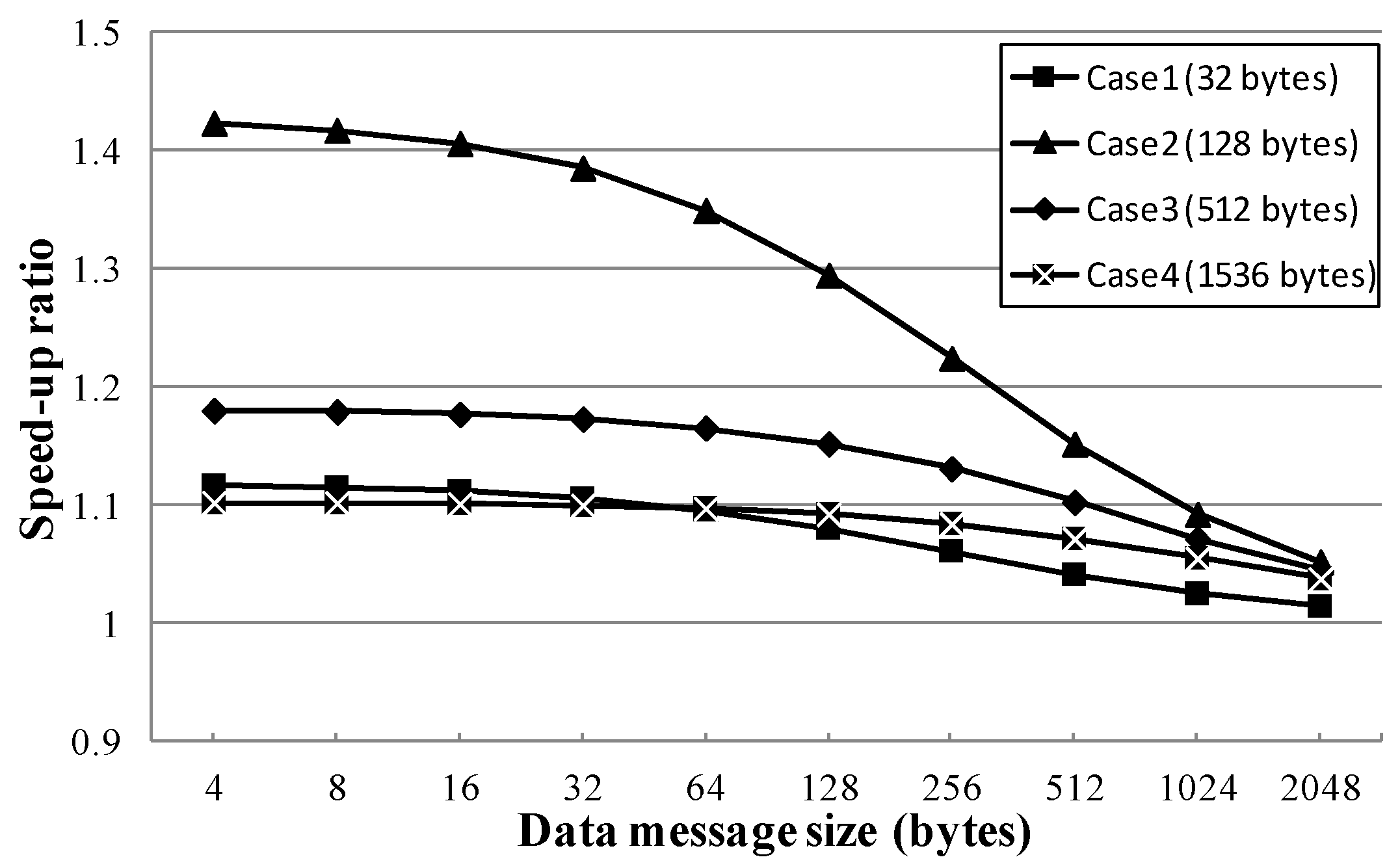
Figure 21 show the speed-up ratios of the APOC algorithm when 4, 8, 16, and 32 processing nodes were in the communicator with the pre-existing data transmission, respectively, compared to the AP algorithm. In these simulations, only the P1 processing node had the pre-existing data transmission, and the pre-existing transmission data sizes were 32, 128, 512, and 1536 bytes, respectively.
In the figures, APOC shows better performance than AP, which cannot change the transmission order. Since APOC features the transmission order change technique, it did not wait (or waited a short time) until the pre-existing data transmission finishes; rather, it performed broadcast communication immediately. Additionally, the synchronization time could be hidden for the communication time for the pre-existing data transmission.
Table 2 shows the best speed-up ratios made by adopting the transmission order change technique, according to the simulation results. When four processing nodes were broadcasting with 4-byte data message and a 32 bytes pre-existing data transmission, the best speed-up ratio (1.105) occurred. When eight processing nodes were broadcasting with 4-byte data message and a 32 bytes pre-existing data transmission, the best speed-up ratio (1.261) occurred. When 16 processing nodes were broadcasting with 4-byte data message and a 128 bytes pre-existing data transmission, the best speed-up ratio (1.255) occurred. Finally, when 32 processing nodes were broadcasting with 4-byte data message and a 128 bytes pre-existing data transmission, the best speed-up ratio (1.423) occurred.
Where N is the number of processing nodes, the number of reduced waiting clock cycles is up to N-2 cycles. Even if the transmission order of P1 in the busy group is changed to the last order and the broadcast communication can begin immediately, P1 will perform the data transmission for the broadcast communication after at least N-2 cycles. Therefore, the performance improvement was limited. Additionally, as the data message size was increased, the ratio of synchronization time to data message transmission time was decreased; therefore, the performance improvement also was decreased.
These simulation results indicate the levels of performance improvement that derive from the use of the transmission order change technique. Although the inter-node transmission order change technique was used in the simulation, the initial change technique would also derive the same levels of performance, as only one processing node (i.e., P1) belongs to the busy group. Therefore, the advantage of the inter-node transmission order change technique was not found in these simulation results; its advantage was that the transmission order of processor nodes could be changed in the busy group also.
5. Implementation and Synthesis Results
To support the atomic pipelined broadcast algorithm with the inter-node transmission order change technique, a modified MPE was modeled by using Verilog-HDL and synthesized.
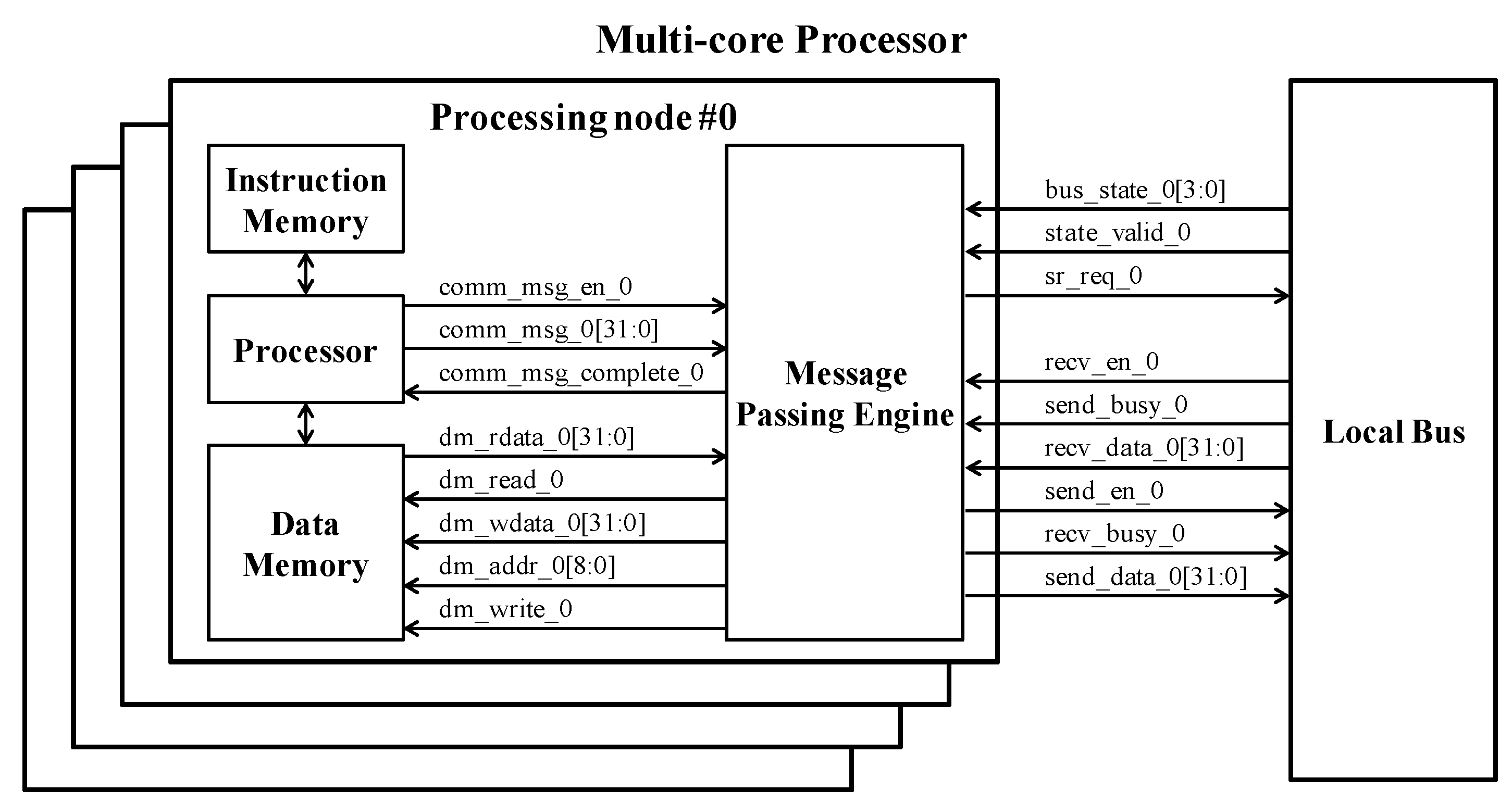
Figure 22 shows the structure of the multi-core processor system that included the modified MPE. The multi-core processor system consisted of four processing nodes and the local bus. Each of the processing nodes comprised of a processor core, 16-KByte instruction memory, 16-Kbyte data memory, and the modified MPE. The processor core was the Yonsei Multi-Processor Unit for Extension (YMPUE), which was designed by the processor laboratory at Yonsei University. It was a five-stage pipeline RISC type, based on MIPS DLX (DeLuXe) architecture [
49].
When the instruction regarding message passing is fetched from instruction memory, the processor core transferred it to the modified MPE after the decode stage. The modified MPE stores the Send and Recv commands directly in the issue queue. When the Bcast command is received, the root node orders the local bus to distribute the value of the status register to all the processing nodes in the communicator. After the communication statuses of the processing nodes are checked, the MPE reads the pre-defined transmission order from the ROM, translates the logical node number into the physical node number, and then determines the transmission order. According to the changed order, the MPEs generate the control messages, which consist of Send (for a head node), Recv (for a tail node), and Fwd (for a body node), and then store them in the issue queue.
To obtain hardware overhead information for the modified MPE, the multi-core processor system was synthesized with a Synopsys Design Compiler, using TSMC 0.18 μm process standard and memory libraries.
Table 3 shows the synthesis results. The modified MPE occupies an area much smaller than the total chip. The logic area of the modified MPE was 2288.1 (i.e., 9152.5 for four processing nodes) equivalent NAND gates. As described in [
22], the logic area of the MPE supporting the initial transmission order change technique is 2108.4 (i.e., 8433.6 for four processing nodes) equivalent NAND gates.
Compared to the previous MPE, the logic area of the modified MPE increased by approximately 8.5%. However, it occupied only 2.1% of the entire chip area. When considering the entire chip area, the logic area of the modified MPE was negligible; therefore, if the modified MPE were used in a multi-core processor system, the total system performance could be improved with only a small increase in the logic area.
Table 4 is the results of power measurement for the synthesized MPE with Synopsys Power Compiler. The total dynamic power was 56.587 mW and the total leakage power was 489.443 uW. The dynamic power of the modified MPE was 4.242 mW and the leakage power was 2.779 uW, which show that the total amount of power consumption used in this multi-core processor system was very low.
6. Conclusions
Since the sequential tree algorithm was presented, various broadcast algorithms were proposed; these include the binary tree, binomial tree, minimum spanning tree, distance minimum spanning tree algorithms, as well as Van de Gejin’s hybrid broadcast and modified hybrid broadcast algorithms. These algorithms offer performance efficiency by tuning network topologies in collective communications, but they cannot utilize the maximum bandwidth for message broadcast, given their restrictive structure. To utilize maximum bandwidth, pipelined broadcast algorithms were proposed to accelerate the processing time of broadcast communication in the operating system level and in the cluster system.
This paper proposed an efficient atomic pipelined broadcast algorithm with the inter-node transmission order change technique. The atomic pipelined broadcast algorithm could drastically reduce the number of synchronizations on multi-core processor systems. This reduction was accomplished by developing a light-weight protocol and employing simple hardware logic, so that the message broadcast could be performed in an atomic fashion with full pipeline utilization.
The proposed inter-node transmission order change technique considered the communication status of the processing node. This technique sorted each of the processing nodes into the free or busy group, in a manner similar to that seen in the initial transmission order change technique. Then, this technique determined the transmission order only in the free group as the pre-defined numeric order; however, for the busy group, it changed the transmission order according to the remaining pre-existing transmission data size. Therefore, the synchronization time could be hidden for the remaining time, until the pre-existing data transmissions finish; as a result, the overall broadcast completion time was reduced.
To validate this approach, the proposed broadcast algorithm was implemented to a bus functional model with SystemC, and the results with various message data sizes and node number were evaluated. To evaluate the performance improvements of the proposed atomic pipelined broadcast algorithm and the proposed inter-node transmission order change technique, many simulations in various communication environments were performed, in which the number of processing nodes, the transmission data message size, and the pre-existing transmission data message size were varied. The simulation results showed that adopting the transmission order change technique could bring about a 1.423 speed-up ratio.
The message passing engine (MPE) with the atomic pipelined broadcast algorithm with the inter-node transmission order change technique was designed by using Verilog-HDL, which supports four processor cores. The logic synthesis results with TSMC 0.18 μm process cell libraries showed that the logic area of the proposed MPE was 2288.1 equivalent NAND gates, which was approximately 2.1% of the entire chip area; therefore, performance improvement could be expected with a small hardware area overhead, if the proposed MPE were to be added to multi-core processor systems.


