Optimal Thermal Design of a Micro Pin-Fin Heat Sink Using Hybrid Fin Heights and Various Perforated Fin Shapes


Abstract
1. Introduction
2. Methodology
2.1. Mathematical Formulation of an MPFHS
2.2. Optimal Design for an MPFHS
3. The Objective Function
Minimization with LMM
4. Numerical Calculation Procedure
- Initialization: A set of fin-geometry design parameters is first specified as the initial guess Bi0, which serves as the basis for the first iteration.
- Direct problem solution: The direct problem is solved using CFD-ACE+ [23]. With the assistance of a subroutine (.dll), the predicted average base temperature Tbw is obtained.
- Jacobian matrix construction: A Jacobian matrix Ψ is constructed according to Equation (23).
- Design variables update: The corrected design variables Bin+1 are calculated using Equation (24). These updated parameters are then substituted into Step 2 to solve the direct problem again.
- Iteration and convergence: Steps 2 to 4 are repeated, and the iterative process follows the minimization procedure of the LMM until the objective function satisfies the convergence criterion ε = 10−4.
5. Results and Discussion
5.1. Grid Independent Test
5.2. The Performances for Existing MPFHSs
5.3. The Optimal Design for MPFHS with Hybrid Fin Heights and Perforations
6. Conclusions
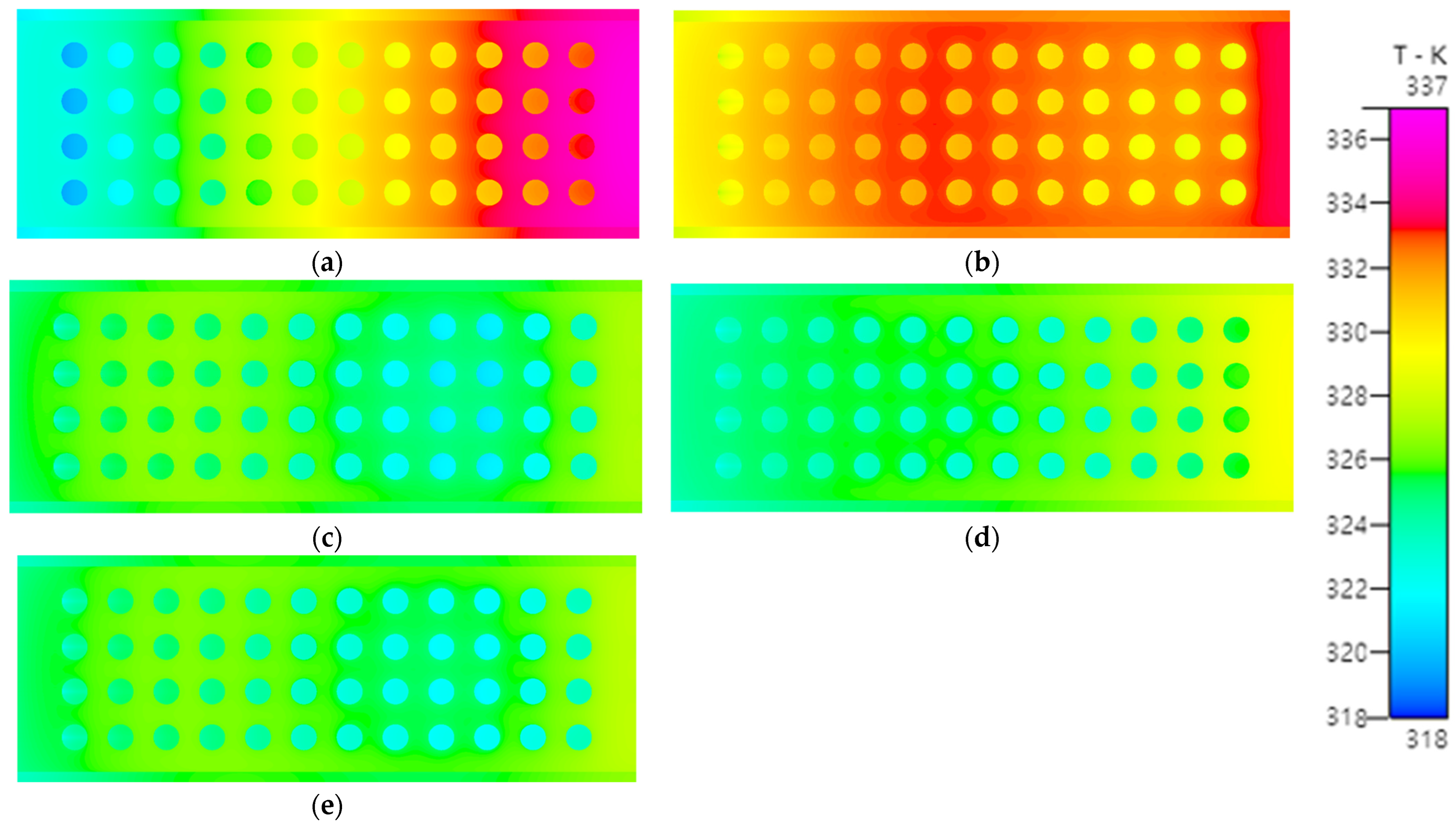
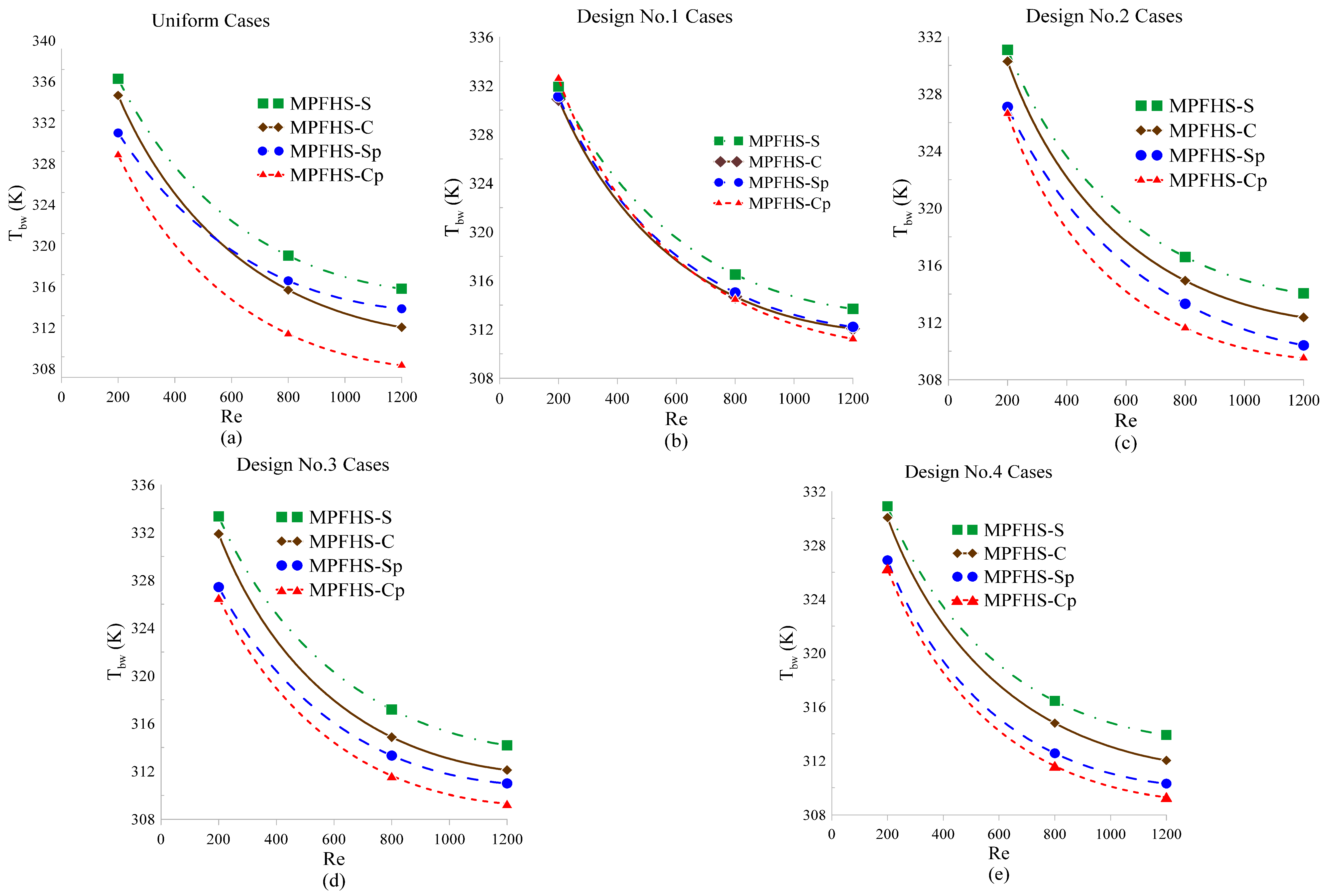
- Temperature distribution
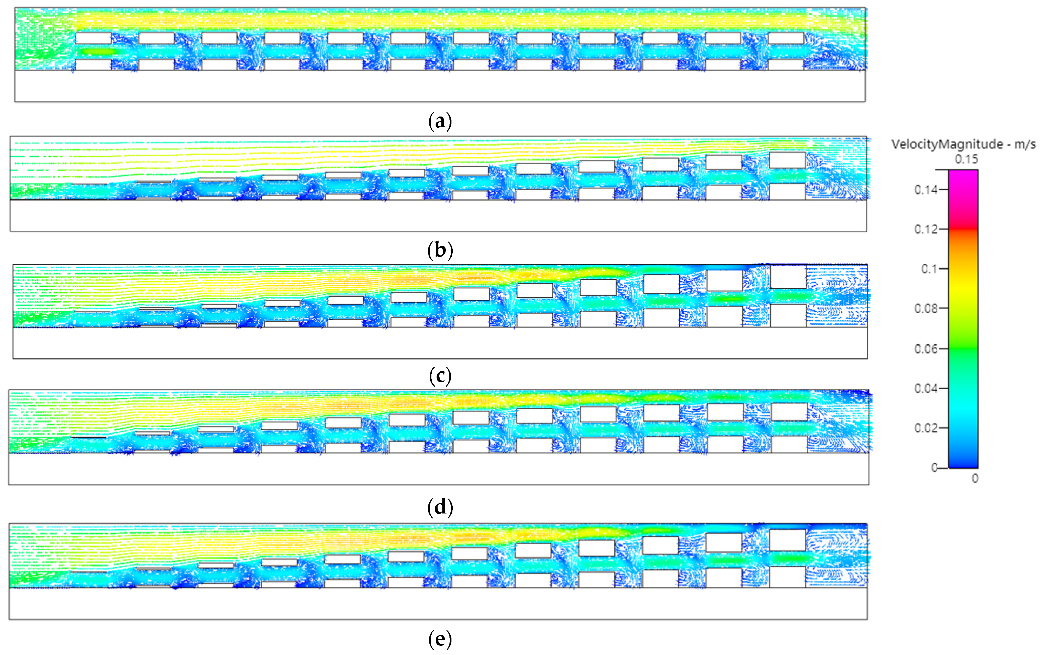
- In perforated designs (MPFHS-SP and MPFHS-CP), the perforations disrupt the thermal boundary layer and promote fluid flow in the wake regions of the fins. This eliminates heat accumulation, leading to further temperature reduction.
- As the inlet Re increases, Tbw decreases across all designs. However, at higher velocities (Re = 800 to 1200), the temperature gap between different height distributions narrows. This suggests that at high flow rates, the fin geometry (specifically whether it is perforated) becomes the dominant factor in cooling, while the influence of height arrangement diminishes.
- 2.
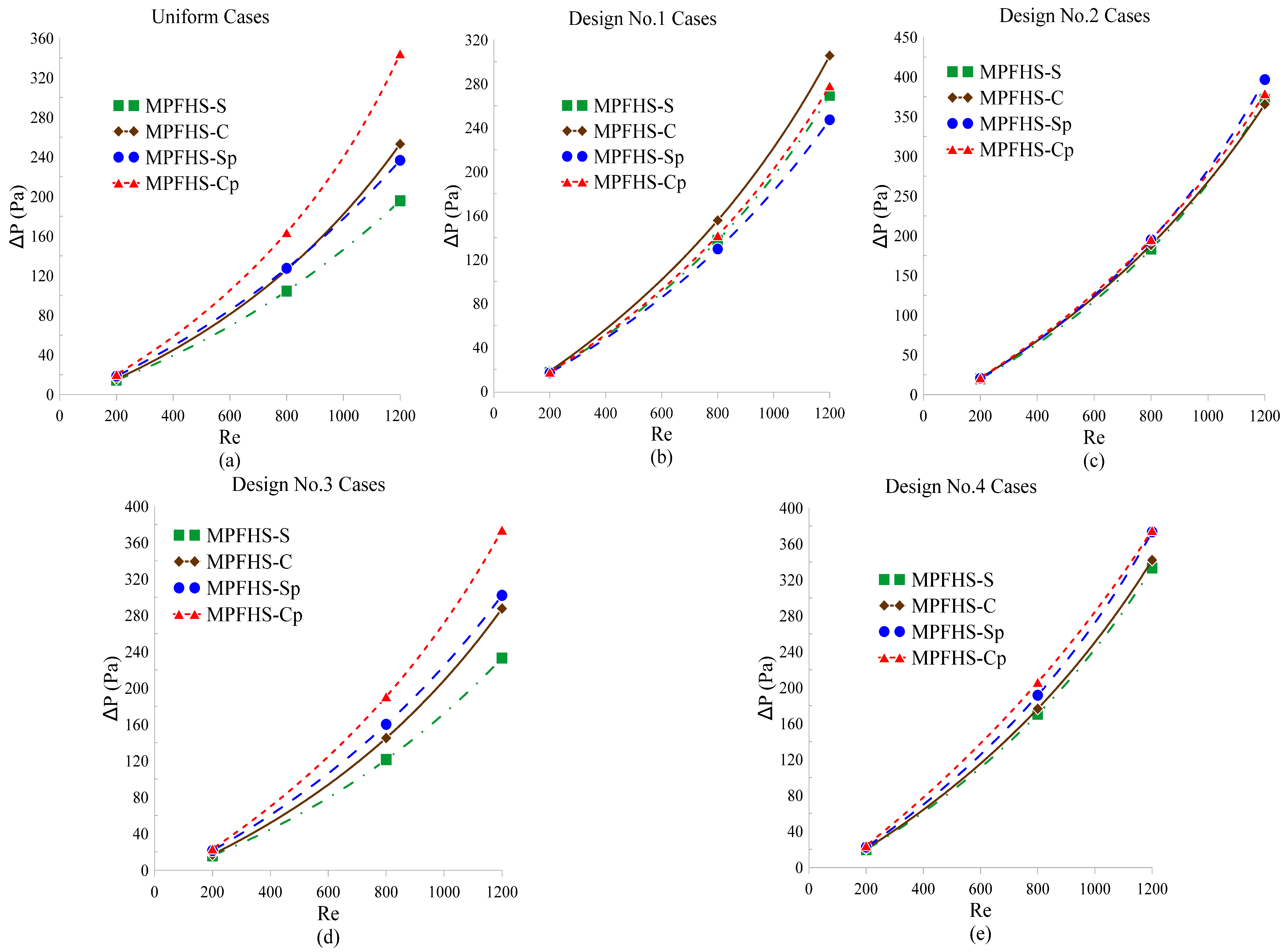
- Pressure-drop characteristics
- Increasing Re from 200 to 800 results in an average pressure-drop increase of over eight times.
- While perforated designs significantly lower temperatures, they introduce a 10–15% increase in pressure drop. This aligns with fluid dynamics theories regarding porosity and pore size in laminar flow regimes.
- 3.
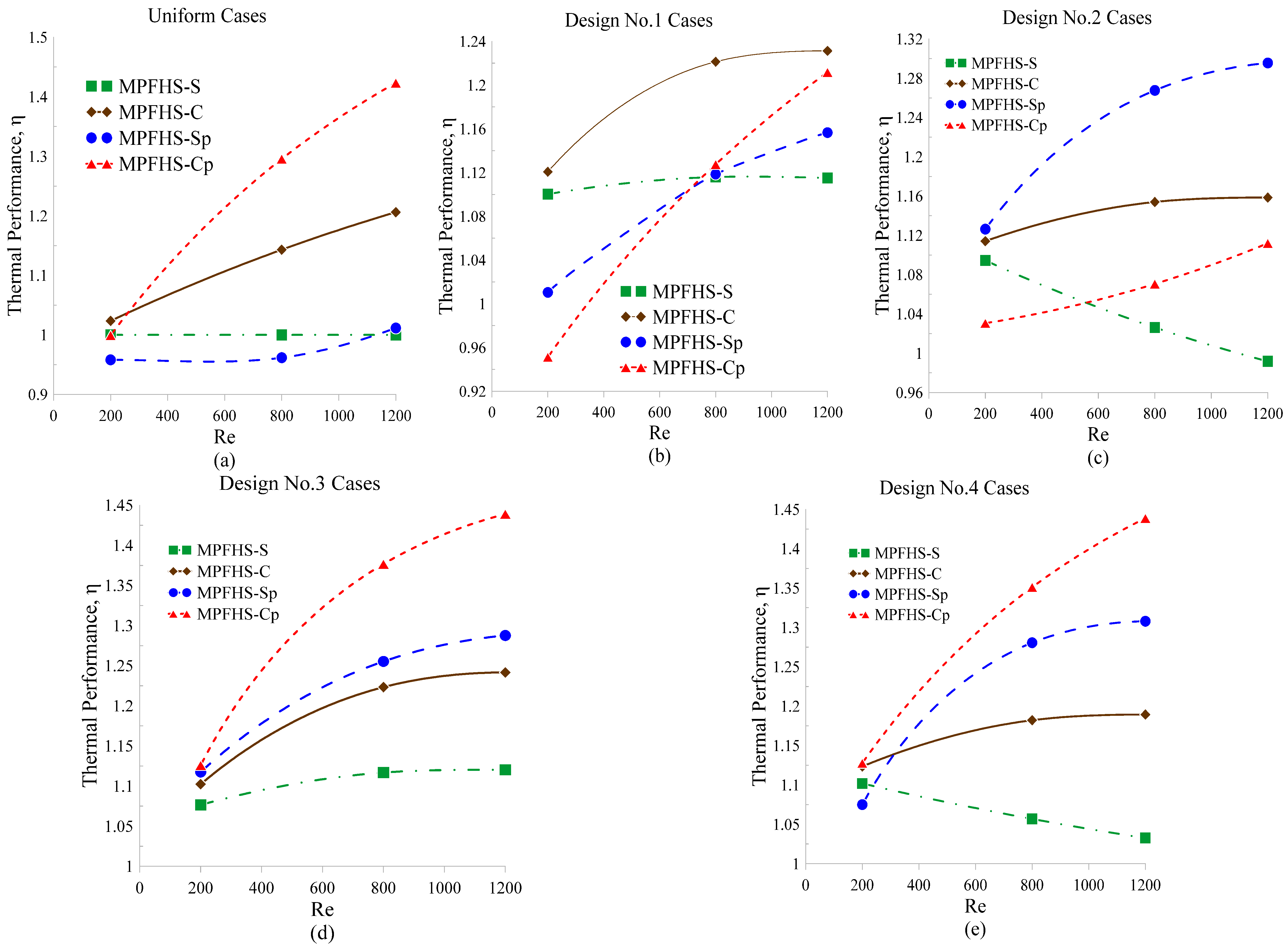
- Thermal performance factor (η)
- At low flow conditions (Re = 200), the optimized Design #4 yields the highest η value. Its perforated configuration achieves significant cooling benefits with only a modest pressure-drop penalty.
- At moderate to high flow conditions (Re = 800 and 1200), the cylindrical-perforated configuration (MPFHS-CP) delivers the most outstanding overall performance, although its increased pressure drop must be considered.
- As the flow velocity increases, Design #3 provides slightly less temperature reduction than Design #4; however, due to its lower pressure drop, it ultimately exhibits a more competitive thermal performance factor.
Author Contributions
Funding
Data Availability Statement
Conflicts of Interest
Abbreviations
| Ab | base area (mm2) |
| Abw | the bottom surface area of the heat sink (mm2) |
| Ac | the liquid interface area (mm2) |
| Acs | the solid–liquid interface area (mm2) |
| As | base area of single fin (mm2) |
| Bi | design variable |
| D | pin fin diameter (mm) |
| Dh | hydraulic diameter (mm) |
| f | friction factor |
| fenhanced | friction factor of the designed case |
| funiform | friction factor of the MPFHS-S uniform case |
| H | height of the heat sink (mm) |
| Hsw | height of the entrance (mm) |
| h | heat transfer coefficient (W/m2-K) |
| hi | height of the ith fin (mm) |
| k | thermal conductivity (W/m-K) |
| L | length of the heat sink (mm) |
| Lin | width of the entry (mm) |
| M | dynamic viscosity of water |
| Nu | Nusselt number |
| Nuenhanced | Nusselt number of the designed case |
| Nuuniform | Nusselt number of the MPFHS-S uniform case |
| q | bottom heat flux (W/m2) |
| qeff | effective heat flux (W/m2) |
| R | radius of perforation (mm) |
| Re | Reynolds number |
| Tavg | average temperature at the solid–liquid interface (K) |
| Tbw | average base temperature (K) |
| Tin | inlet temperature (K) |
| Tout | outlet temperature (K) |
| T∞ | ambient temperature (K) |
| uin | inlet velocity (m/s) |
| V | volume of fins (mm3) |
| Vp | volume of the fin perforation (mm3) |
| W | width of heat sik (mm) |
| Wsw | thickness of fin (mm) |
| Greek symbols | |
| Ψ | Jacobian matrix |
| Δh | height difference (mm) |
| ΔP | pressure drop (N/mm2) |
| η | coefficient of thermal performance |
| δ | height difference between two adjacent pin fins |
| Ω | computational domain |
| ε | stopping criterion |
| ρ | density (kg/m3) |
| μ | weighting parameter |
| μ2 | dynamic viscosity (kg/m-s) |
References
- Irfan, H.M.; Khan, M.M.; Shahzad, M.W. Hydro-thermal performance of an I-shaped pin fin microchannel heat sink with variable pin fin height, thickness and orientation. Int. Commun. Heat Mass Transf. 2025, 160, 108256. [Google Scholar] [CrossRef] [Scilit]
- Abuska, M.; Çorumlu, V. A comparative experimental thermal performance analysis of conical pin fin heat sink with staggered and modified staggered layout under forced convection. Therm. Sci. Eng. Prog. 2023, 37, 101560. [Google Scholar] [CrossRef] [Scilit]
- Al-Damook, A.; Kapur, N.; Summers, J.L.; Thompson, H.M. An experimental and computational investigation of thermal air flows through perforated pin heat sinks. Appl. Therm. Eng. 2015, 89, 365–376. [Google Scholar] [CrossRef] [Scilit]
- Al-Abboodi, N.K.F.; Khalaf, K.A.; Ridha, H.; Al-Azawy, M.G. Thermal and Flow Analysis of Different Shaped Pin Fins for Improved Heat Transfer Rate. Int. J. Heat Technol. 2022, 40, 201–210. [Google Scholar] [CrossRef] [Scilit]
- Alpha, N.A.; Aondover, I.H.; Kuhe, A. Experimental and numerical studies of the effect of perforation configuration on heat transfer enhancement of pin fins heat sink. Heat Transf. 2024, 53, 2525–2555. [Google Scholar] [CrossRef] [Scilit]
- Maji, A.; Bhanja, D.; Patowari, P.K. Numerical investigation on heat transfer enhancement of heat sink using perforated pin fins with inline and staggered arrangement. Appl. Therm. Eng. 2017, 125, 596–616. [Google Scholar] [CrossRef] [Scilit]
- Adhyaru, J.; Uma, M.; Praveena, V.; Sethuramalingam, P. Optimization of Thermal and Pressure Drop Performance in Circular Pin Fin Heat Sinks Using the TOPSIS Method. Energies 2024, 17, 6340. [Google Scholar] [CrossRef] [Scilit]
- Benouis, F.Z.; Amer, Y.O.; Arıcı, M.; Meziane, S. Designing and optimizing a novel heat sink for the enhancement of hydrothermal performances: Modelling and analysis using artificial neural network. Eng. Anal. Bound. Elem. 2023, 155, 766–778. [Google Scholar] [CrossRef] [Scilit]
- Al-Muhsen, N.F.O.; Al-Khafaji, O.R.S.; Ismail, F.B. Thermal Performance Optimization of Perforated Fins for Flat Plate Heat Sinks Using CFD Approach. Int. J. Heat Technol. 2023, 41, 1052–1062. [Google Scholar] [CrossRef] [Scilit]
- Yousfi, A.; Lahcene, B.; Alqurashi, F.; Djamel, S.; Teggar, M.; Laouer, A.; Arici, M.; Kchaou, M. Effect of Trenched Hemispherical Pin Fins on Cooling Performance of Heat Sink. Adv. Sci. Technol. Res. J. 2024, 18, 33–44. [Google Scholar] [CrossRef] [Scilit]
- Yan, Y.; Zhao, T.; He, Z.; Yang, Z.; Zhang, L. Numerical investigation on the characteristics of flow and heat transfer enhancement by micro pin-fin array heat sink with fin-shaped strips. Chem. Eng. Process. Process Intensif. 2021, 160, 108273. [Google Scholar] [CrossRef] [Scilit]
- Wen, M.Y.; Yeh, C.H. Forced convective performance of perforated circular pin-fin heat sinks. Heat Mass Transf. 2017, 53, 1713–1723. [Google Scholar] [CrossRef] [Scilit]
- Kore, S.S.; Yadav, R.; Chinchanikar, S.; Tipole, P.; Dhole, V. Experimental Investigations of Conical Perforations on the Thermal Performance of Cylindrical Pin Fin Heat Sink. Int. J. Ambient Energy 2022, 43, 3431–3442. [Google Scholar] [CrossRef] [Scilit]
- Maji, A.; Deshamukhya, T.; Choubey, G.; Choubey, A. Performance evaluation of perforated pin fin heat sink using particle swarm optimization and MCDM techniques. J. Therm. Anal. Calorim. 2022, 147, 5133–5150. [Google Scholar] [CrossRef] [Scilit]
- Bhandari, P.; Prajapati, Y.K. Thermal performance of open microchannel heat sink with variable pin fin height. Int. J. Therm. Sci. 2021, 159, 106609. [Google Scholar] [CrossRef] [Scilit]
- Li, H.; Jing, D. Hydraulic and thermal performances of micro pin fin heat sink with increasing pin fin height. Case Stud. Therm. Eng. 2024, 53, 103912. [Google Scholar] [CrossRef] [Scilit]
- Hossain, M.I.; Chowdhury, M.S.H.; Ahmed, S.S.U.; Hamja, A.; Siddique, I.J. Forced convective heat transfer over twisted and perforated forked pin fin heat sink: A numerical study. Int. J. Therm. Sci. 2025, 211, 109719. [Google Scholar] [CrossRef] [Scilit]
- Muralikrishna, Y.; Kumar, M.M.J.; Aravind, B.; Sahu, M.K. Comparative studies on performance of plain, perforated, threaded, and threaded–perforated pin fin: A numerical approach. Heat Transf. 2023, 52, 3333–3352. [Google Scholar] [CrossRef] [Scilit]
- Marquardt, D.W. An algorithm for least-squares estimation of nonlinear parameters. J. Soc. Ind. Appl. Math. 1963, 11, 431–441. [Google Scholar] [CrossRef] [Scilit]
- Huang, C.-H.; Liu, L.W. Optimal Position and Perforated Radius of Punched Vortex Generators for Heat Sink. Case Stud. Therm. Eng. 2022, 32, 101916. [Google Scholar] [CrossRef] [Scilit]
- Huang, C.-H.; Chung, K.J. Optimal Design of Perforated Fins for LED Radial Heat Sink Module with Varied Hole Numbers and Sizes. Appl. Therm. Eng. 2024, 242, 122451. [Google Scholar] [CrossRef] [Scilit]
- Huang, C.-H.; Xu, E.H. Optimization of Natural Convection Heat Sinks with Inverted Trapezoidal Fins and Elliptical Perforations. Int. J. Therm. Sci. 2026, 222, 110581. [Google Scholar] [CrossRef] [Scilit]
- ESI-CFD Inc. CFD-ACE+ User’s Manual; ESI-CFD Inc.: Paris, France, 2026. [Google Scholar]








| Property | Copper [16] | Water [15] |
|---|---|---|
| Density ρ(T), kg/m3 | 8960 | 765.33 + 1.8142T − 0.0035T2 |
| Specific Heat Cp(T), J/kg-K | 385 | 28,070 − 281.7T + 1.25T2 − (2.48 × 10⁻³)T3 + (1.857 × 10⁻⁶)T4 |
| Thermal Conductivity k(T), W/m-K | 387.6 | −0.5752 + (6.397 × 10⁻³)T − (8.151 × 10⁻⁶)T2 |
| Dynamic Viscosity μ(T), kg/m-s | N/A | 9.67 × 10⁻² − (8.207 × 10⁻⁴)T + (2.344 × 10⁻⁶)T2 − (2.244 × 10⁻⁹)T3 |
| Grid Numbers | Tbw (K) | ΔP (Pa) | Time (s) |
|---|---|---|---|
| 584,000 | 337.5663 | 14.2014 | 427 |
| 1,068,000 | 337.2982 | 14.3429 | 937 |
| 1,765,000 | 337.1714 | 14.4051 | 2005 |
| 2,729,000 | 337.0996 | 14.4359 | 3547 |
| 4,743,000 | 337.0449 | 14.4750 | 8927 |
| Design Cases | Variables, mm | Tbw, K | Nu | ΔP, N/ | f | η | Iterations |
|---|---|---|---|---|---|---|---|
| MPFHS-S uniform | N/A | 337.0996 | 7.7160 | 14.4360 | 1.2469 | 1 | N/A |
| MPFHS-S Design #1 | Δh = 0.0909 | 331.9544 | 9.0223 | 17.3236 | 1.4963 | 1.1003 | N/A |
| MPFHS-S Design #2 | δ1 = 0.0210, δ2 = 0 | 331.0933 | 9.3825 | 19.7943 | 1.7098 | 1.0945 | N/A |
| MPFHS-S Design #3 | δ1 = 0, δ2 = 0.0119 | 333.3504 | 8.5980 | 16.0065 | 1.3826 | 1.0765 | N/A |
| MPFHS-S Design #4 | δ1 = 0.0253, δ2 = 0.00203 | 330.9095 | 9.4202 | 19.6346 | 1.6960 | 1.1018 | 3 |
| MPFHS-C uniform | N/A | 335.4710 | 8.0973 | 15.5576 | 1.3438 | 1.0235 | N/A |
| MPFHS-C Design #1 | Δh = 0.0909 | 330.9034 | 9.3712 | 18.3684 | 1.5866 | 1.1207 | N/A |
| MPFHS-C Design #2 | δ1 = 0.0210, δ2 = 0 | 330.2790 | 9.7370 | 20.9756 | 1.8118 | 1.1141 | N/A |
| MPFHS-C Design #3 | δ1 = 0, δ2 = 0.0119 | 331.8835 | 9.0257 | 17.2490 | 1.4899 | 1.1023 | N/A |
| MPFHS-C Design #4 | δ1 = 0.0250, δ2 = 0.00217 | 330.0685 | 9.7614 | 20.6122 | 1.7804 | 1.1234 | 3 |
| MPFHS-Sp uniform | R = 0.245 | 331.8134 | 8.0310 | 18.5019 | 1.5981 | 0.9581 | N/A |
| MPFHS-Sp Design #1 | Δh = 0.1252, R = 0.245 | 331.1172 | 8.2053 | 16.8273 | 1.4534 | 1.0104 | N/A |
| MPFHS-Sp Design #2 | δ1 = 0.0139, δ2 = 0.0085, R = 0.245 | 327.0906 | 10.0730 | 22.4807 | 1.9418 | 1.1263 | N/A |
| MPFHS-Sp Design #3 | δ1 = 0, δ2 = 0.0163, R = 0.245 | 327.4307 | 9.8435 | 21.4803 | 1.8553 | 1.1175 | N/A |
| MPFHS-Sp Design #4 | δ1 = 0.0076, δ2 = 0.012, R = 0.245 | 326.9026 | 10.0953 | 22.4950 | 1.9430 | 1.1285 | 7 |
| MPFHS-Cp uniform | R = 0.245 | 329.6698 | 8.6394 | 20.3038 | 1.7537 | 0.9993 | N/A |
| MPFHS-Cp Design #1 | Δh = 0.1277, R = 0.245 | 332.5983 | 7.8153 | 17.4285 | 1.5054 | 0.9512 | N/A |
| MPFHS-Cp Design #2 | δ1 = 0.0139, δ2 = 0.0085, R = 0.245 | 326.6316 | 9.0628 | 21.3705 | 1.8459 | 1.0306 | N/A |
| MPFHS-Cp Design #3 | δ1 = 0, δ2 = 0.0163, R = 0.245 | 326.5518 | 10.1897 | 23.2956 | 2.0122 | 1.1259 | N/A |
| MPFHS-Cp Design #4 | δ1 = 0.0073, δ2 = 0.0122, R = 0.245 | 326.2799 | 10.3358 | 24.1977 | 2.0901 | 1.1276 | 7 |
| Design Cases | Variables, mm | Tbw, K | Nu | ΔP, N/ | f | η | Iterations |
|---|---|---|---|---|---|---|---|
| MPFHS-S uniform | N/A | 319.8525 | 14.7101 | 104.4110 | 0.5637 | 1 | N/A |
| MPFHS-S Design #1 | Δh = 0.0909 | 316.5131 | 17.5597 | 137.5603 | 0.7426 | 1.1159 | N/A |
| MPFHS-S Design #2 | δ1 = 0.0210, δ2 = 0 | 316.5961 | 18.2142 | 183.4002 | 0.9902 | 1.0262 | N/A |
| MPFHS-S Design #3 | δ1 = 0, δ2 = 0.0119 | 317.1862 | 17.2738 | 121.3940 | 0.6554 | 1.1168 | N/A |
| MPFHS-S Design #4 | δ1 = 0.0212, δ2 = 0.00488 | 316.4460 | 18.3032 | 170.3747 | 0.9198 | 1.0568 | 3 |
| MPFHS-C uniform | N/A | 316.5108 | 17.8944 | 125.8346 | 0.6794 | 1.1431 | N/A |
| MPFHS-C Design #1 | Δh = 0.0909 | 314.6902 | 20.5233 | 155.6341 | 0.8402 | 1.2213 | N/A |
| MPFHS-C Design #2 | δ1 = 0.0210, δ2 = 0 | 314.9301 | 20.6723 | 188.5489 | 1.0179 | 1.1540 | N/A |
| MPFHS-C Design #3 | δ1 = 0, δ2 = 0.0119 | 314.8605 | 20.0841 | 145.1710 | 0.7837 | 1.2233 | N/A |
| MPFHS-C Design #4 | δ1 = 0.0198, δ2 = 0.00512 | 314.6010 | 20.7186 | 176.5727 | 0.9532 | 1.1822 | 4 |
| MPFHS-Sp uniform | R = 0.245 | 317.4056 | 15.1211 | 127.4914 | 0.6883 | 0.9617 | N/A |
| MPFHS-Sp Design #1 | Δh = 0.1252, R = 0.245 | 315.0316 | 17.6826 | 129.5873 | 0.6996 | 1.1185 | N/A |
| MPFHS-Sp Design #2 | δ1 = 0.0139, δ2 = 0.0085, R = 0.245 | 313.3127 | 22.8498 | 192.1627 | 1.0374 | 1.2676 | N/A |
| MPFHS-Sp Design #3 | δ1 = 0, δ2 = 0.0163, R = 0.245 | 313.3156 | 21.2986 | 160.2250 | 0.8650 | 1.2553 | N/A |
| MPFHS-Sp Design #4 | δ1 = 0.0112, δ2 = 0.010, R = 0.245 | 312.5615 | 23.0619 | 191.5781 | 1.0342 | 1.2806 | 6 |
| MPFHS-Cp uniform | R = 0.245 | 312.2231 | 22.1328 | 163.5720 | 0.8831 | 1.2955 | N/A |
| MPFHS-Cp Design #1 | Δh = 0.1277, R = 0.245 | 314.4575 | 18.3719 | 141.8884 | 0.7660 | 1.1275 | N/A |
| MPFHS-Cp Design #2 | δ1 = 0.0139, δ2 = 0.0085, R = 0.245 | 311.6250 | 20.0874 | 216.6897 | 1.1698 | 1.0706 | N/A |
| MPFHS-Cp Design #3 | δ1 = 0, δ2 = 0.0163, R = 0.245 | 311.6241 | 24.7566 | 190.7396 | 1.0297 | 1.3767 | N/A |
| MPFHS-Cp Design #4 | δ1 = 0.0076, δ2 = 0.0120, R = 0.245 | 311.6170 | 24.9314 | 206.1241 | 1.1128 | 1.3511 | 7 |
| Design Cases | Variables, mm | Tbw, K | Nu | ΔP, N/ | f | η | Iterations |
|---|---|---|---|---|---|---|---|
| MPFHS-S uniform | N/A | 316.6327 | 17.7049 | 195.6279 | 0.4694 | 1 | N/A |
| MPFHS-S Design #1 | Δh = 0.0909 | 313.6874 | 21.9669 | 269.4579 | 0.6465 | 1.1151 | N/A |
| MPFHS-S Design #2 | δ1 = 0.0210, δ2 = 0 | 314.0482 | 21.7484 | 371.6274 | 0.8917 | 0.9918 | N/A |
| MPFHS-S Design #3 | δ1 = 0, δ2 = 0.0119 | 314.1714 | 21.0279 | 233.0798 | 0.5593 | 1.1203 | N/A |
| MPFHS-S Design #4 | δ1 = 0.0192, δ2 = 0.00544 | 313.6251 | 21.9855 | 333.3209 | 0.7998 | 1.0326 | 4 |
| MPFHS-C uniform | N/A | 312.8753 | 23.2670 | 253.0251 | 0.6071 | 1.2061 | N/A |
| MPFHS-C Design #1 | Δh = 0.0909 | 312.0686 | 25.2968 | 305.6197 | 0.7333 | 1.2313 | N/A |
| MPFHS-C Design #2 | δ1 = 0.0210, δ2 = 0 | 312.3603 | 25.2638 | 365.5430 | 0.8771 | 1.1585 | N/A |
| MPFHS-C Design #3 | δ1 = 0, δ2 = 0.0119 | 312.1036 | 24.9955 | 287.5973 | 0.6900 | 1.2416 | N/A |
| MPFHS-C Design #4 | δ1 = 0.0188, δ2 = 0.00565 | 312.0289 | 25.3709 | 342.1155 | 0.8208 | 1.1894 | 4 |
| MPFHS-Sp uniform | R = 0.245 | 314.6771 | 19.0793 | 236.5524 | 0.5676 | 1.0115 | N/A |
| MPFHS-Sp Design #1 | Δh = 0.1252, R = 0.245 | 312.2134 | 22.1368 | 247.1973 | 0.5931 | 1.1565 | N/A |
| MPFHS-Sp Design #2 | δ1 = 0.0139, δ2 = 0.0085, R = 0.245 | 310.4023 | 28.4841 | 374.7283 | 0.8991 | 1.2955 | N/A |
| MPFHS-Sp Design #3 | δ1 = 0, δ2 = 0.0163, R = 0.245 | 310.9830 | 26.3499 | 302.0859 | 0.7248 | 1.2876 | N/A |
| MPFHS-Sp Design #4 | δ1 = 0.0112, δ2 = 0.010, R = 0.245 | 310.3080 | 28.7244 | 373.4462 | 0.8960 | 1.3079 | 7 |
| MPFHS-Cp uniform | R = 0.245 | 309.1643 | 30.4235 | 344.2940 | 0.8261 | 1.4232 | N/A |
| MPFHS-Cp Design #1 | Δh = 0.1277, R = 0.245 | 311.2265 | 24.1244 | 278.1428 | 0.6673 | 1.2117 | N/A |
| MPFHS-Cp Design #2 | δ1 = 0.0139, δ2 = 0.0085, R = 0.245 | 309.5173 | 25.2235 | 411.4036 | 0.9871 | 1.1120 | N/A |
| MPFHS-Cp Design #3 | δ1 = 0, δ2 = 0.0163, R = 0.245 | 309.3166 | 31.6227 | 374.0497 | 0.8975 | 1.4390 | N/A |
| MPFHS-Cp Design #4 | δ1 = 0.00023, δ2 = 0.0162, R = 0.245 | 309.1425 | 31.6459 | 375.1789 | 0.9002 | 1.4387 | 7 |
Disclaimer/Publisher’s Note: The statements, opinions and data contained in all publications are solely those of the individual author(s) and contributor(s) and not of MDPI and/or the editor(s). MDPI and/or the editor(s) disclaim responsibility for any injury to people or property resulting from any ideas, methods, instructions or products referred to in the content. |
© 2026 by the authors. Licensee MDPI, Basel, Switzerland. This article is an open access article distributed under the terms and conditions of the Creative Commons Attribution (CC BY) license.
Share and Cite
Huang, C.-H.; Hsu, C.-P. Optimal Thermal Design of a Micro Pin-Fin Heat Sink Using Hybrid Fin Heights and Various Perforated Fin Shapes. Mathematics 2026, 14, 3227. https://doi.org/10.3390/math14173227
Huang C-H, Hsu C-P. Optimal Thermal Design of a Micro Pin-Fin Heat Sink Using Hybrid Fin Heights and Various Perforated Fin Shapes. Mathematics. 2026; 14(17):3227. https://doi.org/10.3390/math14173227
Chicago/Turabian StyleHuang, Cheng-Hung, and Ching-Ping Hsu. 2026. "Optimal Thermal Design of a Micro Pin-Fin Heat Sink Using Hybrid Fin Heights and Various Perforated Fin Shapes" Mathematics 14, no. 17: 3227. https://doi.org/10.3390/math14173227
APA StyleHuang, C.-H., & Hsu, C.-P. (2026). Optimal Thermal Design of a Micro Pin-Fin Heat Sink Using Hybrid Fin Heights and Various Perforated Fin Shapes. Mathematics, 14(17), 3227. https://doi.org/10.3390/math14173227