Article

Optimal Thermal Design of a Micro Pin-Fin Heat Sink Using Hybrid Fin Heights and Various Perforated Fin Shapes


Department of Systems and Naval Mechatronic Engineering, National Cheng Kung University, Tainan 701, Taiwan
*
Author to whom correspondence should be addressed.
Mathematics 2026, 14(17), 3227; https://doi.org/10.3390/math14173227
Submission received: 10 August 2026 / Revised: 31 August 2026 / Accepted: 2 September 2026 / Published: 7 September 2026

Abstract

This study presents a numerical optimization framework for a micro pin-fin heat sink (MPFHS). Three-dimensional conjugate heat transfer and fluid flow are simulated using the commercial CFD code CFD-ACE+. Coupled with the Levenberg–Marquardt method (LMM), the geometric parameters are optimized to minimize the base wall temperature Tbw under a constant total fin-volume constraint. The investigation assesses four pin-fin architectures—solid square (MPFHS-S), solid cylindrical (MPFHS-C), perforated square (MPFHS-SP), and perforated cylindrical (MPFHS-CP)—across five distinct fin-height distributions: uniform, constant-step (Design #1), increasing-step (Design #2), decreasing-step (Design #3), and hybrid-step (Design #4). The results demonstrate that perforated fins significantly enhance heat transfer by disrupting the thermal boundary layer and mitigating heat accumulation in the wake region. Within the allowable geometric constraints, larger perforation radii provide superior cooling performance. Among all examined configurations, the LMM-optimized Design #4 consistently achieves the lowest base temperature across the entire Reynolds number range. Specifically, for the MPFHS-CP configuration, the optimized Design #4 yields Tbw values of 326.279 K, 311.617 K, and 309.142 K at Reynolds numbers of 200, 800, and 1200, respectively. As the Reynolds number increases, the temperature differences among the configurations gradually diminish, indicating that forced convection increasingly dominates the flow and reduces the sensitivity to fin geometry. Pressure-drop analysis reveals that perforated configurations incur an approximate 10–15% higher pressure loss compared to their solid counterparts. To evaluate the overall thermo-fluid behavior, the thermal performance factor η is employed to evaluate the trade-off between heat transfer enhancement and the associated pressure-drop penalty. The results confirm that cylindrical fins consistently outperform square fins, with perforations providing an additional reduction in Tbw. Overall, combining a hybrid fin-height distribution with perforated pin fins presents an effective strategy for optimizing MPFHS performance, offering practical guidelines for the thermal management of high-power electronic devices.

1. Introduction

With the continuous rise in power density for high-performance computing (HPC) and fifth-generation (5G) chip packaging, heat sources confined to just a few square millimeters have become increasingly common. In recent years, numerous studies have begun integrating micro pin fins into microchannels to enhance thermal performance by increasing the heat transfer surface area, inducing secondary flows, and disrupting the thermal boundary layer. The optimal design of cooling modules primarily aims to achieve the highest possible thermal performance for the system. In this context, predicting the optimal height and perforation size of micro pin-fin heat sinks (MPFHSs) serves as an effective design solution.
Many researchers have devoted considerable effort to investigating the cooling performance improvements achievable with MPFHS. For instance, Sallar et al. [1] designed an I-shaped fin microchannel heat sink, in which varying the fin inclination angle (15–90°) created converging–diverging flow passages, resulting in a 29% enhancement in the thermal performance factor. This type of structure enhances heat transfer through flow disturbance, but the associated increase in pressure drop must be carefully considered. Abuska and Çorumlu [2] compared the heat transfer performance of five heat sink models under forced convection. Their results showed that conical pin-fin structures can significantly enhance local vortex intensity and increase the convective heat transfer coefficient. Moreover, all models exhibited a substantial decrease in thermal resistance with increasing Reynolds number, with the modified staggered conical pin-fin design achieving thermal resistance values 5.3–3.5% lower than those of the staggered conical and flat heat sinks. Al-Damook et al. [3] conducted experimental and CFD investigations to systematically examine how the design of porous pin-fin heat sinks (PHSs) affects heat transfer and pressure loss. The results showed that the porous design can simultaneously enhance heat transfer performance while reducing flow resistance and fan power consumption.
Al-Abboodi et al. [4] conducted numerical simulations on microchannel pin-fin heat sinks to compare the forced convection heat transfer and fluid performance of four different fin geometries in both inline and staggered arrangements. The study found that elliptical fins achieved the highest Nusselt number and heat transfer coefficient across all Reynolds numbers, indicating the best thermal performance, while cylindrical fins exhibited the lowest temperature and superior heat transfer compared to square and teardrop fins, especially at high flow velocities. Alpha et al. [5] studied staggered pin fins in rectangular channels, investigating various fin configurations to evaluate their effect on heat transfer enhancement under forced convection. The results showed that perforated fins significantly outperformed solid fins in heat transfer, and the more complex the perforation pattern, the greater the enhancement. Specifically, L-type perforations increased the Nusselt number by approximately 8–9%, LT-type by about 33%, and LTV-type achieved the highest enhancement at 67%. Maji et al. [6] compared inline and staggered perforated fins and found that elliptical perforated fins in a staggered arrangement increased the Nusselt number by 41.1%, with an optimal perforation size. These studies confirm that perforation designs must balance heat transfer enhancement with pressure-drop mitigation and should be optimized in conjunction with the fin arrangement. Adhyaru et al. [7] applied the TOPSIS method, combined with the Taguchi approach and regression modeling, to optimize the number, thickness, and inlet flow rate of cylindrical fins. They reported that the inlet flow rate accounted for 63.4% of the impact on the heat source temperature, highlighting the critical importance of the flow parameter.
Artificial intelligence techniques have also been applied to heat sink design. Benouis et al. [8] developed a backpropagation neural network (ANN) model to predict local Nusselt numbers with an error of less than 3%, and proposed a hybrid pin-fin heat sink (HPFHS) design that improved the thermal performance factor by 50%. Such methods can effectively shorten the design cycle, although they require a substantial amount of training data. Al-Muhsen et al. [9] used a three-dimensional CFD model to investigate how different perforation shapes (circular, square, and triangular) and locations (bottom, middle, and top) on plate-type heat sink fins affect overall thermal performance, and validated the model through experiments. The results showed that when the perforation is placed closer to the fin tip, the temperature gradient along the fin decreases and the temperature distribution becomes more uniform. This indicates that top-mounted perforations are most effective in conducting heat toward the fin tip and expanding the convective heat transfer area. Yousfi et al. [10] conducted numerical simulations on trenched hemispherical pin fins to systematically investigate the effects of trench number and trench thickness on flow and heat transfer characteristics. The results showed that trenching not only enhances heat transfer but also strengthens the wake vortices behind the fins, leading to reduced wall temperatures and increased cooling air velocity, thereby improving the overall cooling efficiency.
Yan et al. [11] conducted a comparative study of various channel configurations and fin geometries, finding that the SMFAP exhibited the best overall thermal–hydraulic performance. At a Re of 1200, the average Nu of the SMFAP reached nearly twice that of the traditional IMCP. The pressure drop of the SMFAP was approximately 1.5 times that of the IMCP and 1.7 times that of the SMCP. Wen and Yeh [12] analyzed the heat transfer performance and pressure-drop characteristics of two types of cylindrical pin-fin heat sinks, one with a solid base plate and the other with a base plate containing a small central hole, under forced convection in a channel. Through flow visualization, they revealed the mechanisms of fluid–structure interaction and clarified how the base-hole size, fin height, and flow-field interaction influence the forced convection cooling performance and pressure drop.
Kore et al. [13] compared solid pin fins with conical perforated pin fins of various perforation numbers and sizes in a rectangular channel under forced convection, evaluating thermal resistance, pressure drop, and overall performance. As the number of conical perforations increased from two to five, the Nusselt number at the highest Reynolds number condition increased by approximately 11.9%, 13.9%, 16.9%, and 23.6%, respectively, compared with the solid heat sink. Maji et al. [14] combined particle swarm optimization (PSO) with a multi-criteria decision-making (MCDM) approach to systematically analyze the effects of perforation number, perforation size, and base-plate geometry. They found that a triangular base plate combined with five perforations (each 5 mm in diameter) achieved the best overall performance.
Bhandari and Prajapati [15] focused on open microchannel heat sinks and analyzed the influence of fin height on the available flow passage. They reported that the heat transfer rate reaches its peak when the fin height increases to 1.5 mm, while further increases lead to performance degradation due to flow separation and vortex formation. This result highlights the coupled effect between fin height and channel geometry. Based on the study of Bhandari and Prajapati [15], Li and Jing [16] examined the impact of different fin-height variation patterns on the thermal–hydraulic performance of micro pin-fin heat sinks (MPFHSs). They proposed three height distribution configurations, uniform height steps, increasing height steps, and decreasing height steps, and found that the increasing-step design provided the best thermal performance at low Reynolds numbers, while the decreasing-step design yielded the lowest pressure drop at high Reynolds numbers. Based on the above findings, an interesting question arises: Are there any designs that lie between the increasing-step and decreasing-step configurations and offer better thermal performance?
Hybrid designs that combine multiple geometric features can further overcome performance limitations. For instance, Hossain et al. [17] proposed fork-shaped twisted perforated fins, where the combination of slots and perforations increased the heat transfer performance factor (HTPF) by 158% compared with conventional cylindrical fins. They also identified a twist angle of 55° as the optimal parameter. Muralikrishna et al. [18] performed numerical simulations on cylindrical pin-fin heat sinks with various surface modifications—including threading, triangular perforations, and a hybrid of threading and perforations. The results showed that combining the smallest thread pitch with the largest perforation size most effectively increased the convective surface area and turbulence intensity. This configuration achieved the lowest local and peak fin temperatures and maximized heat transfer across a range of flow velocities and heat flux conditions.
By utilizing the concept of hybrid designs, the objective of this work is to design hybrid fin-height distributions in microchannel heat sinks based on the theoretical foundation of Li and Jing [16]. The present study will combine the increasing-step and decreasing-step fin configurations, and the objective is to minimize the base-plate temperature of the heat sink by utilizing an optimal design algorithm.
The LMM [19] is an optimization algorithm commonly used for solving nonlinear least-squares problems and is particularly suitable for optimal design tasks in engineering applications. For example, Huang and Liu [20] applied the LMM to estimate the design parameters of a delta winglet vortex generator (VG), for improving the heat dissipation performance of a pin-fin heat sink. Huang and Chung [21] utilized the LMM to determine the optimal design of perforated fins for a light-emitting diode (LED) radial heat dissipation module with varied hole numbers and sizes under natural convection conditions, while Huang and Xu [22] employed it to estimate the optimal design variables for a three-dimensional natural convection heat sink featuring an inverted trapezoidal geometry with elliptical perforations. Building upon these contributions, the present study employs the LMM approach to perform multi-parameter optimization.
From the above review, it can be observed that, under a fixed fin-volume constraint, the optimal design of microchannel heat sinks featuring both hybrid height-step distributions and perforated fins for achieving the minimum base temperature has not yet been investigated. Therefore, the objective of this study is to employ the LMM optimization procedure to estimate the optimal perforation radius and fin-height distribution weights of a micro pin-fin heat sink (MPFHS) under a fixed-volume condition, in order to achieve the best possible base temperature performance.

2. Methodology

In modern engineering practice, problem-solving methodologies are generally categorized into two main types: direct problems and design (or inverse) problems. A direct problem determines the system response from known governing equations and fully specified boundary conditions and inputs. In this framework, the primary objective is to compute the resulting physical quantities and performance metrics from these prescribed parameters. At present, a commercial software package, such as CFD-ACE+ (v2026.0, Paris, France) [23], is widely used to solve these problems through numerical simulations of thermal-fluid flows, heat transfer, and related physical phenomena.
In contrast, a design problem focuses on identifying a set of conditions or configurations capable of achieving the desired performance. Such problems often involve geometric optimization or system-level design considerations. The procedure typically begins with the formulation of an objective function (also referred to as a cost function), which quantitatively measures the difference between the predicted results and the desired performance.
Defining the objective function is a critical step, as it establishes the foundation of the entire optimization framework. Once formulated, an appropriate iterative optimization algorithm is employed to update the design variables. Guided by gradient information or defined error-evaluation criteria, the algorithm progressively refines the design parameters until convergence is achieved. This systematic process efficiently determines the optimal configuration, ensuring the final design fulfills the target performance criteria within the specified constraints.

2.1. Mathematical Formulation of an MPFHS

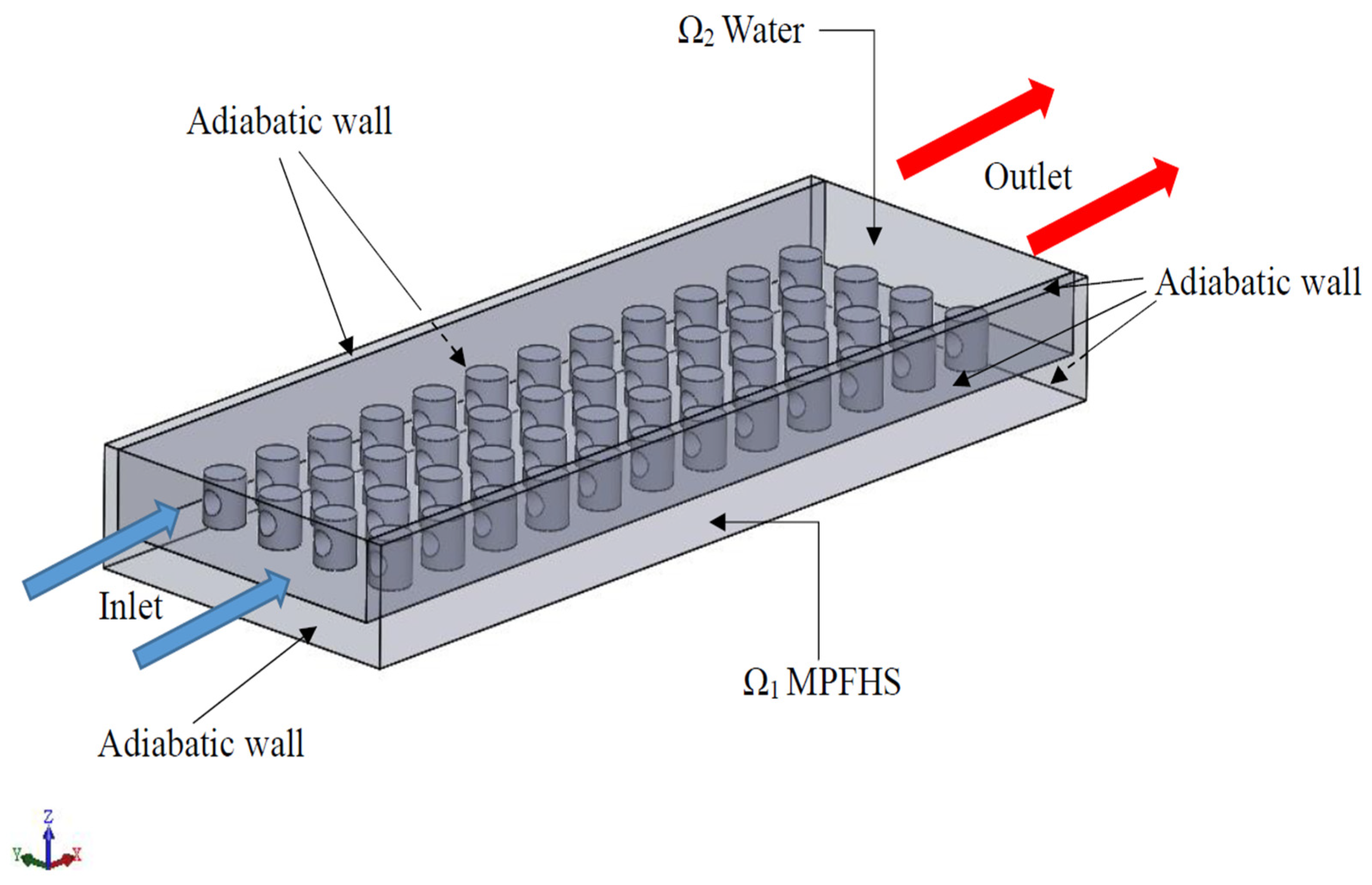
The computational model of the MPFHS used in this study is shown in Figure 1. The entire computational domain consists of two regions: Ω1 represents the MPFHS, and Ω2 represents the pure-water flow region. The thermophysical properties of the pure water and copper heat sink are listed in Table 1. It is clear that the water properties are treated as temperature-dependent [15] and this makes the problem nonlinear. A heat flux of q = 150,000 W/m2 is applied at the bottom surface Ab of the heat sink and the ambient temperature is taken as T = 26.85 °C (300 K). The heat-sink surfaces are subject to a conduction–convective conjugate boundary condition with water and the channel walls are assumed adiabatic.
The steady-state heat conduction equation for the three-dimensional MPFHS region Ω1 can be expressed as
k 1 2 T 1 = 0 ;   in   Ω 1
where T11) denotes the temperature distribution in the MPFHS, and k1 is the thermal conductivity of the MPFHS. A constant heat flux q is applied at the bottom plate of MPFHS Ab, i.e.,
( k 1 ) T 1 z   | A b = q
The front boundary of the domain is defined as the water inlet, where a uniform inlet velocity uin of 0.053 m/s (Re = 200), 0.212 m/s (Re = 800), and 0.318 m/s (Re = 1200) is prescribed.
The fluid flow in region Ω2 is assumed to be a three-dimensional, incompressible, steady-state laminar flow. The effects of gravity, buoyancy, thermal radiation, and viscous dissipation are neglected. In addition, the governing equations are formulated by considering the temperature-dependent density, ρ2(T2), dynamic viscosity, μ2(T2), specific heat capacity, cp2(T2), and thermal conductivity, k2(T2) [15]. The continuity, momentum, and energy equations in Ω2 are given by Equations (3)–(5), respectively.
ρ 2 ( T 2 ) U = 0
ρ 2 ( T 2 ) U U = P + μ 2 ( T 2 ) [ U + ( U ) T ]
ρ 2 ( T 2 ) c p 2 ( T 2 ) U T 2 = k 2 ( T 2 ) T 2
In the above equations, T22) denotes the temperature distribution in the water, U is velocity matrix and P is pressure.
In addition, the Ω1–Ω2 interface is assumed to satisfy the perfect thermal contact condition, i.e., k 1 T 1 n = k 2 T 2 n   and   T 1 = T 2 . The software package CFD-ACE+ is utilized to compute the solutions for the above direct problem in Ω.
In addition, the following parameters are defined for further investigation [16]:
Nusselt number, Nu:
Nu = h D h k 2
Heat transfer coefficient, h:
h = q e f f T a v g T
Reynolds Number, Re:
Re = ρ 2 u in   D h μ 2
Hydraulic diameter, Dh:
D h = 4 A c L i n
Friction factor, f:
f = Δ P ( ρ 2 u i n 2 / 2 ) ( L i n / D h )
Thermal performance factor, η:
η = ( N u e n h a n c e d N u u n i f o r m ) ( f e n h a n c e d f u n i f o r m ) 1 3
Effective heat flux, qeff:
q e f f = q A b w A c s
Here, Tbw is the average base temperature, Tavg is the average temperature at the solid–liquid interface, T is the ambient temperature, Abw is the bottom surface area of the heat sink, Acs is the solid–liquid interface area, k2 is the thermal conductivity of water, q is the bottom heat flux, Dh is the hydraulic diameter of the inlet channel, uin is the inlet velocity, Lin is the inlet width, ρ2 is the density of water, μ2 is the dynamic viscosity of water, and ΔP is the pressure difference between the inlet and outlet. The subscript ‘enhanced’ denotes the cases after design enhancement, and the subscript ‘uniform’ refers to the MPFHS-S uniform configuration.
A non-slip boundary condition is imposed on all solid walls, meaning the velocity on every wall surface is set to zero. Using CFD-ACE+, the three-dimensional conjugate heat transfer problem within the MPFHS and the pure-water flow regions can be solved.

2.2. Optimal Design for an MPFHS

This study extends the MPFHS design originally proposed by Li and Jing [16], who introduced four fin-height distribution configurations: the uniform fin-height arrangement (referred to as uniform in the present work), the constant-step fin-height distribution (Design #1), the increasing-step fin-height distribution (Design #2), and the decreasing-step fin-height distribution (Design #3). In the uniform arrangement, all fins have the same height. In Design #1, the height difference, Δh, between two adjacent fins remains constant throughout the heat sink. In Design #2, the fin height, hi, increases from the inlet to the outlet, and the height difference between adjacent fins, Δhi, increases along the flow direction with a uniform positive increment, δ1. Conversely, in Design #3, although the fin height, hi, also increases from the inlet to the outlet, the height difference between adjacent fins, Δhi, decreases along the flow direction with a uniform negative increment, δ2.
Building upon the above MPFHS configurations, the present study combines the Design #2 and Design #3 fin arrangements. While maintaining the overall heat-sink volume and the height of the first-row fins at the inlet h1, a hybrid fin-height configuration, referred to as Design #4, is proposed in conjunction with an additional perforation design. The design parameters include the values of δ1, δ2, and the perforation radius R, with the objective of achieving the lowest possible Tbw.
Design #2 and Design #3 [16] are combined to form a hybrid height-step distribution (i.e., Design #4), where its fin-height equation can be obtained as:
h i = h 1 + δ 1 i ( i 1 ) 2 + δ 2 12 ( 12 1 ) 2 ( 12 i ) ( 12 + 1 i ) 2   ,   i   =   2 ,   3 , , 12
Here h1 denotes the first fin height and its value is fixed and specified. It should be noted that when δ2 = 0, Equation (13) denotes the Design #2 arrangement, while when δ1 = 0, Equation (13) represents the Design #3 arrangement.
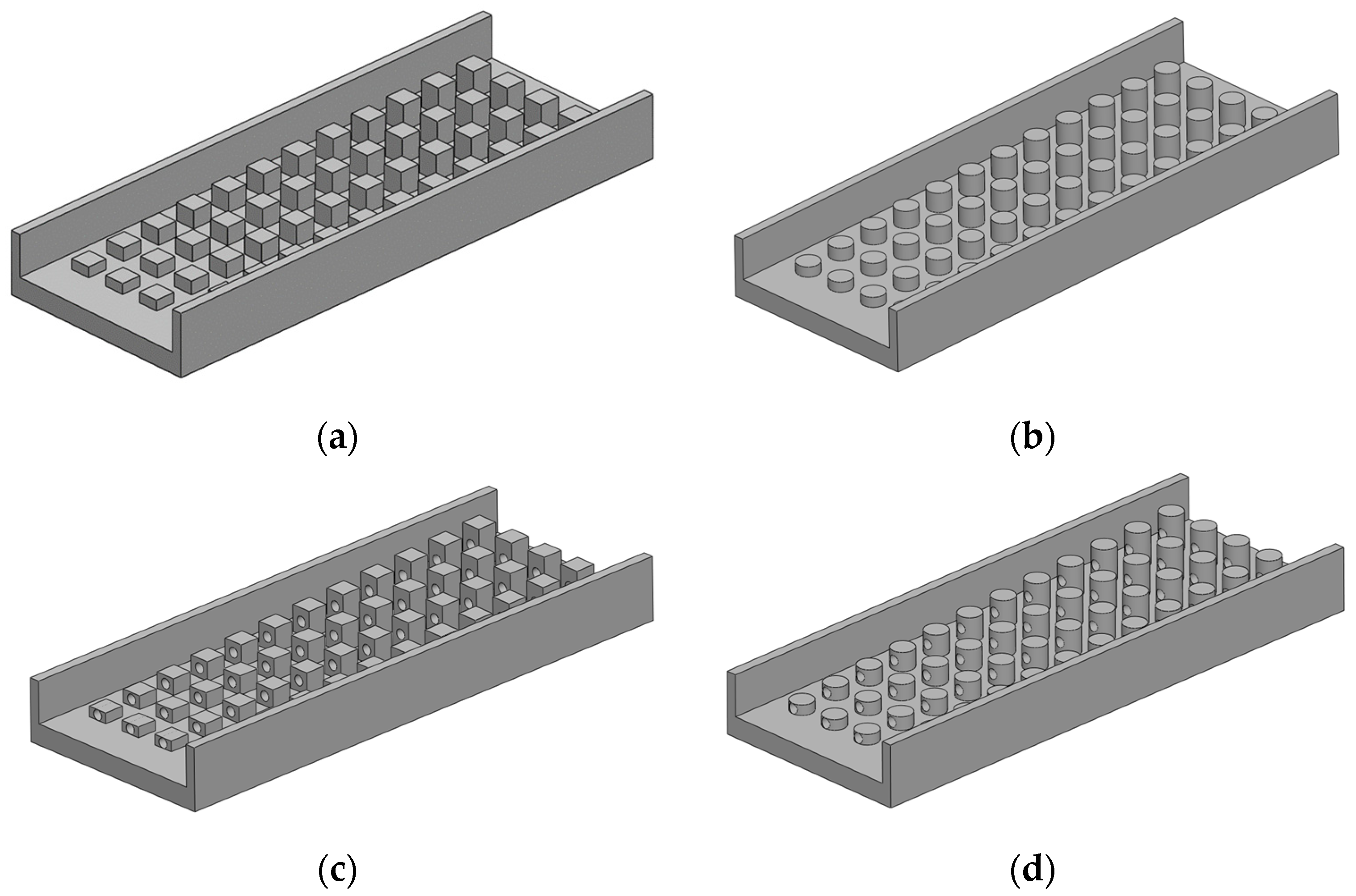
In addition, four different fin geometries are considered for MPFHS in the work, they are square fin MPFHS-S, circular fin MPFHS-C, square fin with perforations MPFHS-Sp and circular fin with perforations MPFHS-Cp. The resulting four fin configurations are shown in Figure 2 for the Design #4 fin-height arrangement.
The total fin volume with perforations in one column of heat sink, i.e., 12 pin fins, for the Design #1 and Design #4 MPFHSs can be given in Equations (14) and (15), respectively:
V = 12 h 1 A s + 66 Δ h A s 12 V p
V = 12 h 1 A s + δ 1 i = 1 11 i i + 1 2 + δ 2 i = 1 11 132 i i 1 2 A s 12 V p = 12 h 1 A s + ( 286 δ 1 + 506 δ 2 ) A s 12 V p
where Vp denotes the fin perforation volumes. In Equation (15), δ2 = 0 and δ1 = 0 denote the total fin volume for the Design #2 and Design #3 MPFHSs, respectively. For unperforated fins, Vp = 0.
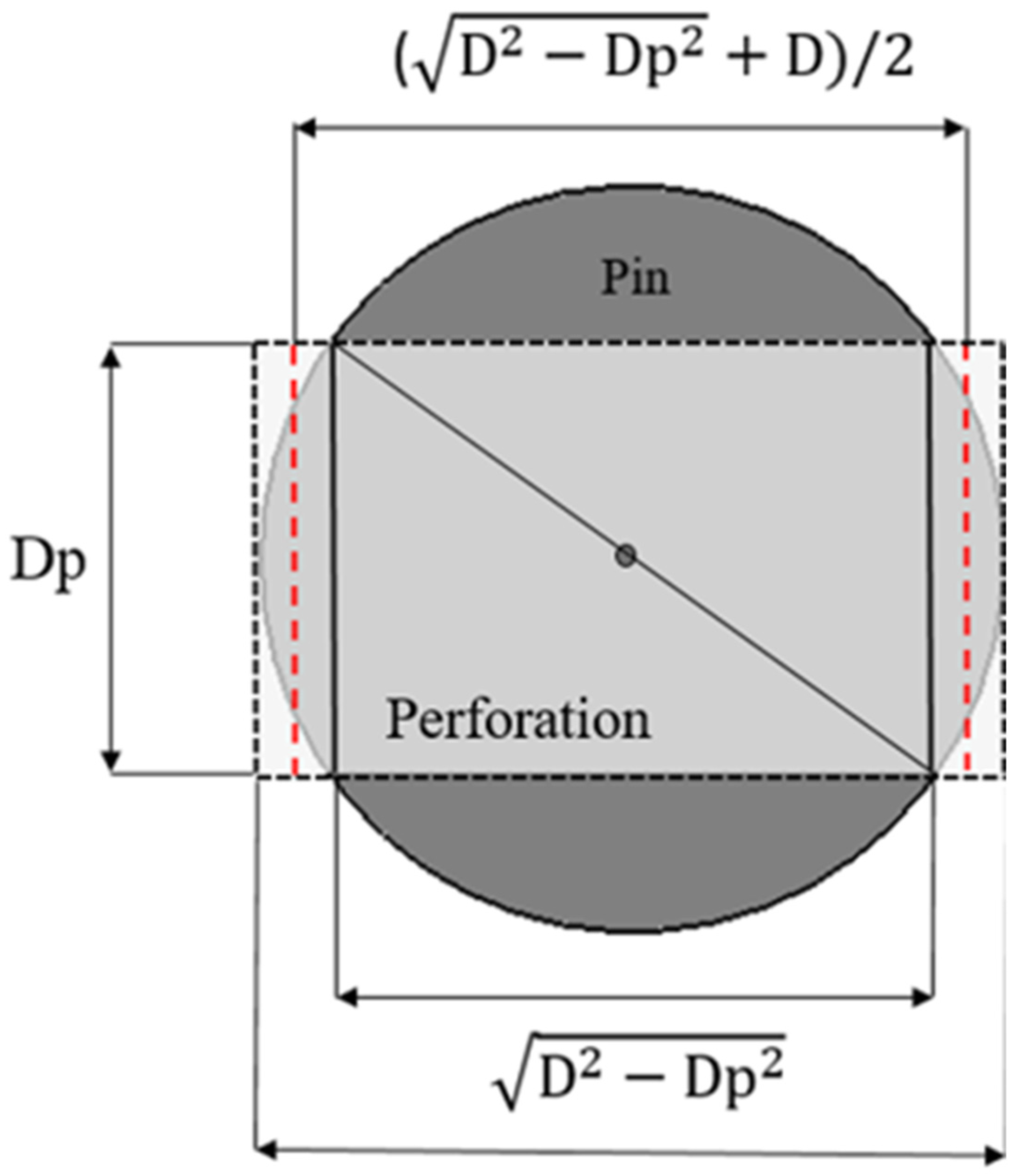
Since the perforation volume of MPFHS-Cp, Vp in Equation (15), cannot be calculated precisely, an approximate method is adopted in this study and Figure 3 indicates how to calculate the approximation perforation volume for MPFHS-Cp. The perforation volume Vp is approximated by multiplying the cross-sectional area of the perforation by the average value of the circumscribed and inscribed lengths between the perforation and the pin fin. The relations are expressed as follows:
V P   = ( D 2 D P 2 ) + D 2 × π D P 2 4
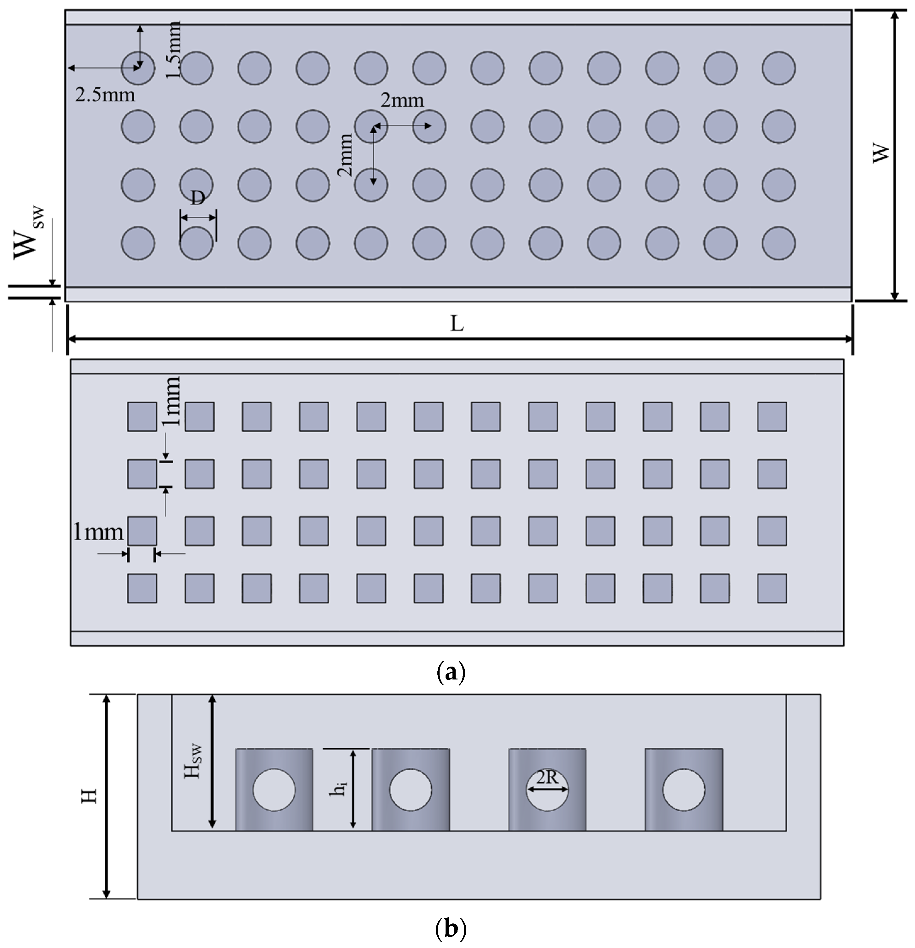
The overall geometry and arrangement of the MPFHS-Sp and MPFHS-Cp used in this study are shown in Figure 4, where L = 27 mm, W = 10 mm, and H = 3 mm. The inlet height HSW = 2 mm, the center-to-center fin spacing is 2 mm, and the wall thickness WSW = 0.5 mm.

3. The Objective Function

To solve this optimal design problem, the minimization of average base temperature Tbw is taken as the objective, and is defined as
J [ Ω ( B i ) ] = [ T bw ( B i ) ] 2 ,   i = 1   to   3
where B = Bi = {Β1, Β2, Β3} = {δ1, δ2, R} denote the design variables, where R = Dp/2. The purpose of this work is to determine the optimal geometric shape B for the MPFHS. Through the minimization of the objective function (17), a three-dimensional heat-sink configuration capable of achieving the lowest base temperature can be systematically obtained.

Minimization with LMM

According to the minimization procedure of the LMM [19], the objective function in Equation (17) is differentiated with respect to each unknown design variable Bi, and the right-hand side of the equation is set to zero. The mathematical definition is given as follows:
J [ Ω ( B i ) ] B i   = T bw ( B i ) B i [ T bw ] = 0 ,   I = 1   to   n
Since Equation (18) constitutes a nonlinear system, a Taylor series expansion of Tbw(Bi) is performed while neglecting the higher-order terms, thereby yielding a linear equation. In addition, to improve computational efficiency, a damping factor μ that controls the convergence rate is introduced. By combining this with the LMM, the MPFHS design problem can be solved. The corresponding mathematical formulations for LMM are expressed as follows [19]:
( F + μ n I ) Δ B = E
F = ψ T ψ
E = ψ T T b w
Δ B = B n + 1 B n
In the above equations, the superscript n denotes the iteration number, and the superscript T represents the matrix transpose, I is the identity matrix, and Ψ is the Jacobian matrix. The Jacobian matrix is evaluated numerically by perturbing each design variable individually, substituting the perturbed values into the direct problem, and calculating the corresponding changes in the average base temperature. Its mathematical definition is given as follows:
ψ = T bw B T
Based on the above definitions, Equation (23) can be rewritten in the following form:
B n + 1 = B n + ( Ψ T Ψ + μ n I ) 1 Ψ T T b w
In Equation (24), the selection of the damping factor μ is crucial, as it affects the convergence characteristics and the number of iterations during the computation. In general, μ is a positive variable. When μ = 0, Equation (24) reduces to the mathematical form of Newton’s method. When μ approaches infinity, Equation (24) transforms into the form of the Steepest Descent method. Therefore, to ensure the stability of the computational process, the Steepest Descent method is adopted at the beginning of the iterative procedure by selecting a very large value of μ. As the solution gradually approaches the correct value, the convergence rate of the Steepest Descent method becomes slow. At this stage, the value of μ is gradually reduced. When μ eventually approaches zero, the computed objective value becomes close to the initially expected value, and the equation then takes the form of Newton’s method. In this way, the solution of the MPFHS design problem can be approached iteratively.

4. Numerical Calculation Procedure

Based on the theoretical derivations and governing equations established in Section 2 and Section 3, the LMM can be employed to solve the MPFHS design problem. The calculation procedure of the algorithm can be systematically summarized as follows:
  • Initialization: A set of fin-geometry design parameters is first specified as the initial guess Bi0, which serves as the basis for the first iteration.
  • Direct problem solution: The direct problem is solved using CFD-ACE+ [23]. With the assistance of a subroutine (.dll), the predicted average base temperature Tbw is obtained.
  • Jacobian matrix construction: A Jacobian matrix Ψ is constructed according to Equation (23).
  • Design variables update: The corrected design variables Bin+1 are calculated using Equation (24). These updated parameters are then substituted into Step 2 to solve the direct problem again.
  • Iteration and convergence: Steps 2 to 4 are repeated, and the iterative process follows the minimization procedure of the LMM until the objective function satisfies the convergence criterion ε = 10−4.

5. Results and Discussion

This study compares four different fin configurations, square pin fins, circular pin fins, perforated square pin fins, and perforated circular pin fins, utilized in the uniform and Design #1 to Design #4 MPFHSs. Numerical simulations are conducted to calculate the performances of these MPFHSs in terms of the average base temperature Tbw, Nusselt number Nu, pressure drop ΔP, friction factor f and thermal performance factor η, under various Reynolds numbers. The objective of this work is to identify an MPFHS that achieves the lowest average base temperature Tbw.

5.1. Grid Independent Test

In this study, a systematic grid-independence test was conducted to determine an appropriate mesh density for the uniform MPFHS-S configuration with a fin height of 1 mm. For the case with T = 300 K, q = 150,000 W/m2 and Re = 200 [15], five different mesh sizes were evaluated, 584,000; 1,068,000; 1,765,000; 2,729,000; and 4,743,000 cells, while monitoring two key parameters, ΔP and Tbw. In addition, the computation time for each case was also recorded. Convergence was considered achieved when the relative residual dropped below 1 × 10⁻⁵, and the maximum number of iterations for each simulation was set to 1000.
The results show that as the mesh count increases, the variations in ΔP and Tbw gradually stabilize. In particular, at 2,729,000 cells, the results are already close to full convergence, i.e., ΔP differs by only +0.146% compared with the finest mesh, and Tbw is lower by merely 0.016%. This indicates that the solution is sufficiently converged and that further refinement yields only marginal accuracy improvements. On the other hand, computation time grows nonlinearly with the number of cells, ranging from 7 to 148 min. The 2,729,000 cell case requires approximately 59 min, about 57% less time than the finest mesh, demonstrating a clear improvement in computational efficiency. Considering both accuracy and efficiency, the mesh with 2,729,000 cells was selected as the standard mesh for this study. The detailed results of the grid-independence test are presented in Table 2. The computed Tbw obtained in this work using 2,729,000 cells is 337.0996 K, whereas Bhandari and Prajapati [15] reported a value of approximately 338 K in Figure 11 of their work. The close agreement between these results confirms the accuracy of the present numerical solution.
The parameters h1 = 0.5 mm and V = 12 mm3 are fixed for all design cases considered in this study; therefore, the perforation radius R must be less than 0.25 mm. However, due to manufacturing limitations, the thickness of the material between the perforation and the outer surface of the pin fin cannot be too thin. Consequently, R is restricted to a maximum value of 0.245 mm, and the additional constraint R ≤ 0.245 mm is imposed during the optimization process.

5.2. The Performances for Existing MPFHSs

Before investigating the optimal design of MPFHS with hybrid fin heights for both solid and perforated fins, it is essential first to evaluate the hydraulic and thermal performance of the existing heat sinks, namely the uniform, Design #1, Design #2, and Design #3 fin-height configurations, across the four fin geometries: MPFHS-S, MPFHS-C, MPFHS-Sp and MPFHS-Cp.
For the solid-fin case (Vp = 0) in the MPFHS-S and MPFHS-C configurations, the design variable Δh for Design #1 can be determined using Equation (14). In Design #2, where δ2 = 0, the design variable δ1 can be obtained directly from Equation (15). Similarly, in Design #3, where δ1 = 0, the design variable δ2 can also be determined directly from Equation (15). Subsequently, the values of Tbw, Nu, ΔP, f, η and number of iterations can be calculated and are summarized in Table 3, Table 4 and Table 5 for Re = 200, 800, and 1200, respectively.
For the perforated-fin cases in the MPFHS-Sp and MPFHS-Cp configurations, an initial value of R is assumed and Δh is evaluated from Equation (14). The LMM is then applied to minimize the objective function and determine the optimal design variables (R, Δh). Likewise, for Design #2 (δ2 = 0) and Design #3 (δ1 = 0), the optimal sets (R, δ1) and (R, δ2) are obtained using the same procedure under the volume constraint in Equation (15).
However, for Design #2, the volume removed by the perforations is redistributed to increase the fin height in order to satisfy the constant-volume constraint. Consequently, some fins become taller than the channel height, resulting in failure of the grid generation process. To avoid this numerical difficulty, the parameter δ2 cannot be set to zero. Instead, δ2 = 0.0085 is adopted in the present study, which ensures that all fin heights remain below the channel height. Because this value is sufficiently small, the geometric characteristics of Design #2 are essentially preserved.
The results indicate that the optimized perforation radius consistently reaches its upper bound R = 0.245 mm, demonstrating that a larger perforation radius yields a more significant reduction in the average base temperature Tbw within the investigated design space. The computed design variables, along with the corresponding values of Tbw, Nu, ΔP, f, and η, are also summarized in Table 3, Table 4 and Table 5 for Re = 200, 800, and 1200, respectively. It is evident that the Tbw values for the Design #1, Design #2, and Design #3 configurations are consistently lower than those of the uniform arrangement. This indicates that the designs proposed by Li and Jing [16] remain effective for the present MPFHSs with different pin-fin geometries. In addition, circular fins always perform better than square fins, and fin perforation further reduces Tbw.

5.3. The Optimal Design for MPFHS with Hybrid Fin Heights and Perforations

The present study combines the Design #2 and Design #3 fin-height configurations to construct a hybrid fin-height arrangement, referred to as Design #4. Based on the previous results, the perforation radius was found to attain its maximum allowable value for optimal cooling performance under the specified h1. Consequently, R is fixed at 0.245 mm and excluded from the set of design variables in the subsequent optimization. Therefore, the design variable set for both the solid-fin and perforated-fin cases is defined as {δ1, δ2}.
An initial value of δ2 is first specified, and δ1 is subsequently determined from Equation (15). The LMM is then employed to minimize the objective function and obtain the optimal values of the design variables {δ1, δ2}. The computed design variables, together with the corresponding values of Tbw, Nu, ΔP, f, η and the number of iterations are also summarized in Table 3, Table 4 and Table 5 for Re = 200, 800, and 1200, respectively. For the MPFHS-S Design #4 case at Re = 200, with the initial guess {δ10, δ20} = {0, 0.0119}, corresponding to the geometry of MPFHS-S Design #3, only three iterations are required to obtain the optimal values of {δ1, δ2} = {0.0253, 0.00203}. The corresponding Tbw values at the initial step and after each iteration are 333.3504 K, 331.0934 K, 330.9156 K, and 330.9095 K, respectively. This implies a rapid convergence rate for the LMM in the current fin profile design problem.
These tables show that, for every pin-fin geometry, the Tbw values of the Design #4 arrangement are the lowest among all four designs. This confirms that the proposed hybrid fin-height configuration offers the lowest Tbw among the existing designs. Consistent with earlier observations, the Design #4 results also demonstrate that circular fins outperform square fins, and that fin perforation further decreases Tbw.
Based on the LMM optimization results, the optimized weighting factor δ2 exhibits different trends with increasing flow velocity for the non-perforated and perforated designs. For the non-perforated designs, δ2 increases gradually as the flow velocity increases, although its value remains sufficiently small that the optimized configuration still closely resembles Design #2. This result indicates that increasing the fin height toward the channel outlet enhances heat transfer, while adequate clearance above the fins must be maintained to facilitate fluid flow and minimize the average base temperature. In contrast, the perforated designs yield larger values of δ2, with only slight variations as the flow velocity increases.
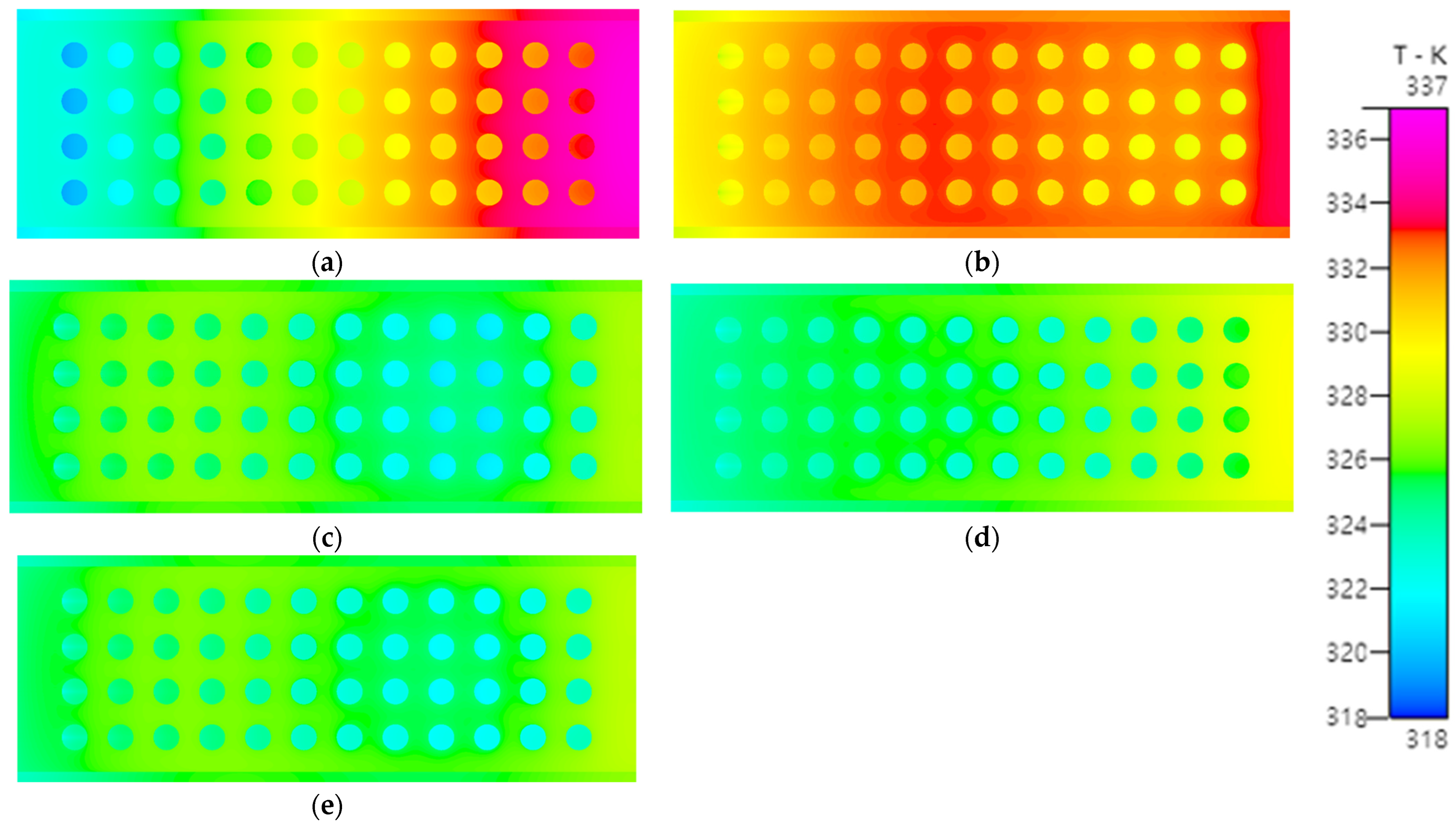
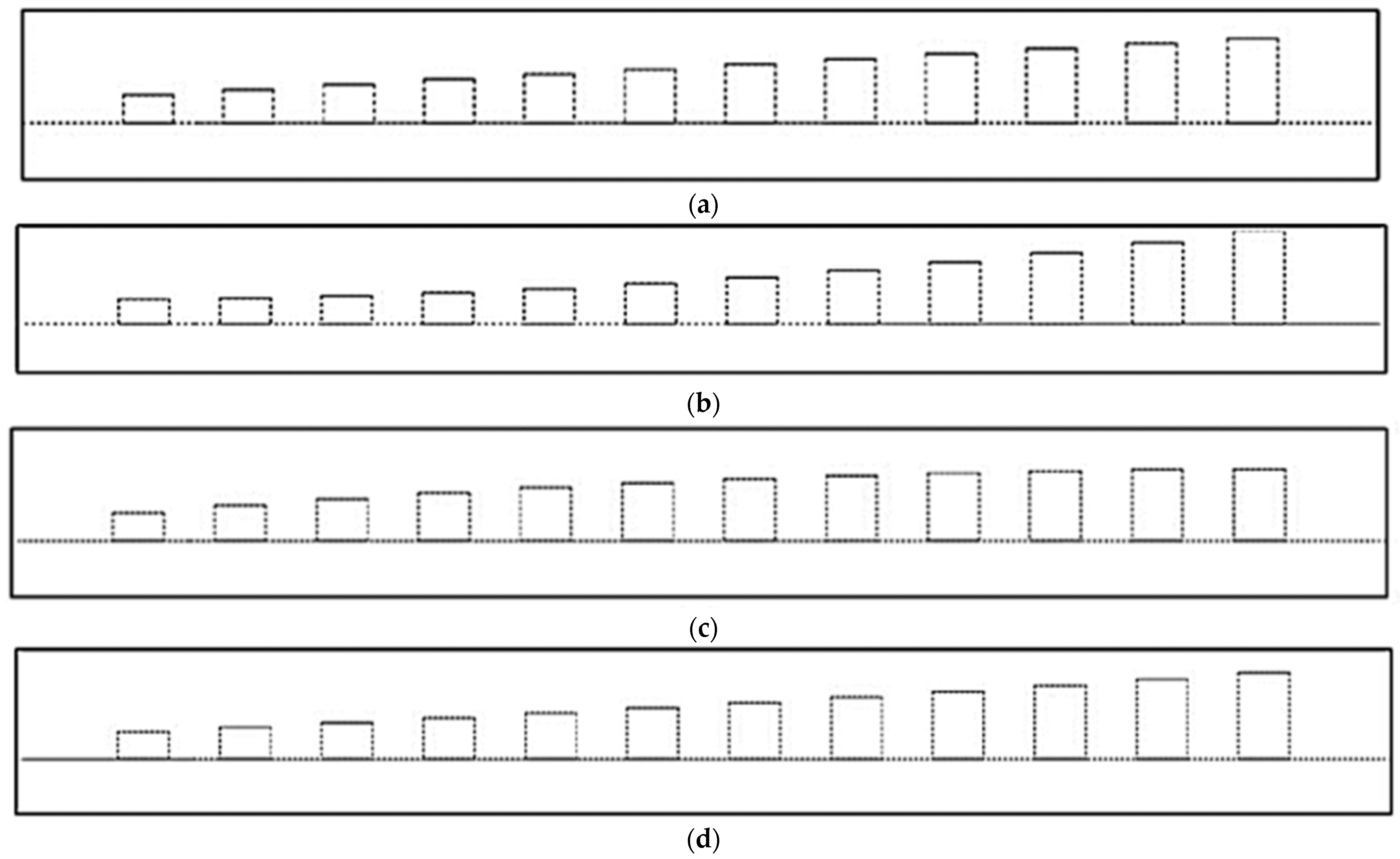
Figure 5a, Figure 5b, Figure 5c, Figure 5d, and Figure 5e respectively present the top-view temperature distributions of the uniform design, Design #1, Design #2, Design #3, and the optimized Design #4 MPFHS-CP at Re = 200. It is observed that the temperature distributions of the Design #2, Design #3, and Design #4 heat sinks are significantly lower than those of the uniform design and Design #1. Among Design #2, Design #3, and Design #4, the Design #3 heat sink exhibits higher temperatures, while the temperatures of the Design #2 and Design #4 heat sinks are close to each other. As stated earlier, the estimated δ2 for the Design #4 arrangement is relatively small, indicating that the fin-height profiles of Design #2 and Design #4 should be similar. However, due to the hybrid fin-height arrangement, the front and rear fin heights of Design #4 are higher and lower, respectively, than those of Design #2, as illustrated in Figure 6. Consequently, the temperature distribution of Design #4 appears more uniform, resulting in the lowest Tbw.
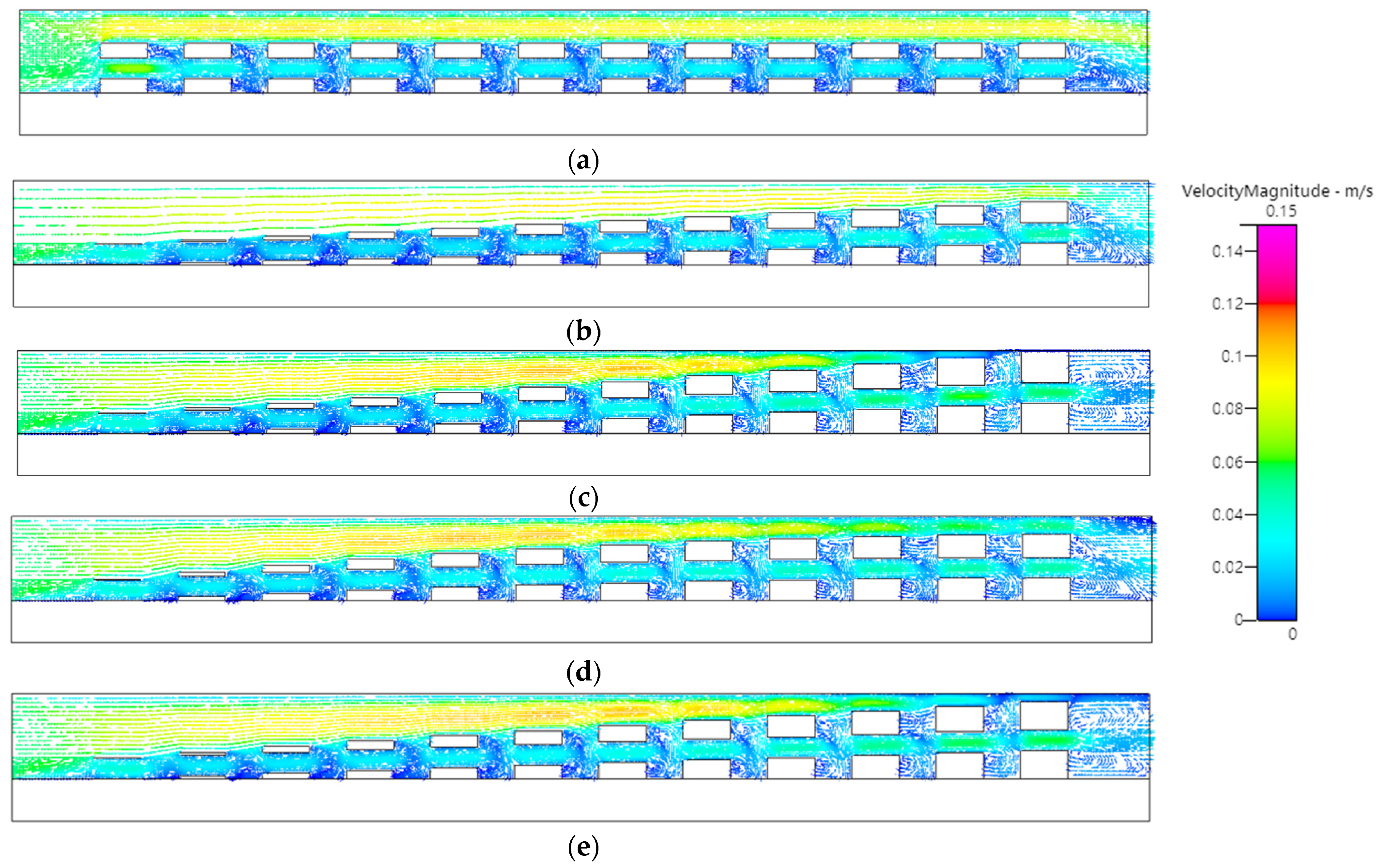
Figure 7a–e show the velocity distributions at Re = 200 and y = 4 mm cross-sections for the uniform design, Design #1, Design #2, Design #3, and Design #4 MPFHS-CP. From Figure 7c it can be observed that fin height h12 (last pin fin) is excessively high, blocking the water flow near the top region. Although the water velocity through the perforations increases, the heat dissipation capability becomes less effective. In the Design #4 heat sink Figure 7e, the fin height in this region is reduced, allowing water to pass through the top area more easily, which enhances the cooling performance and further reduces Tbw.
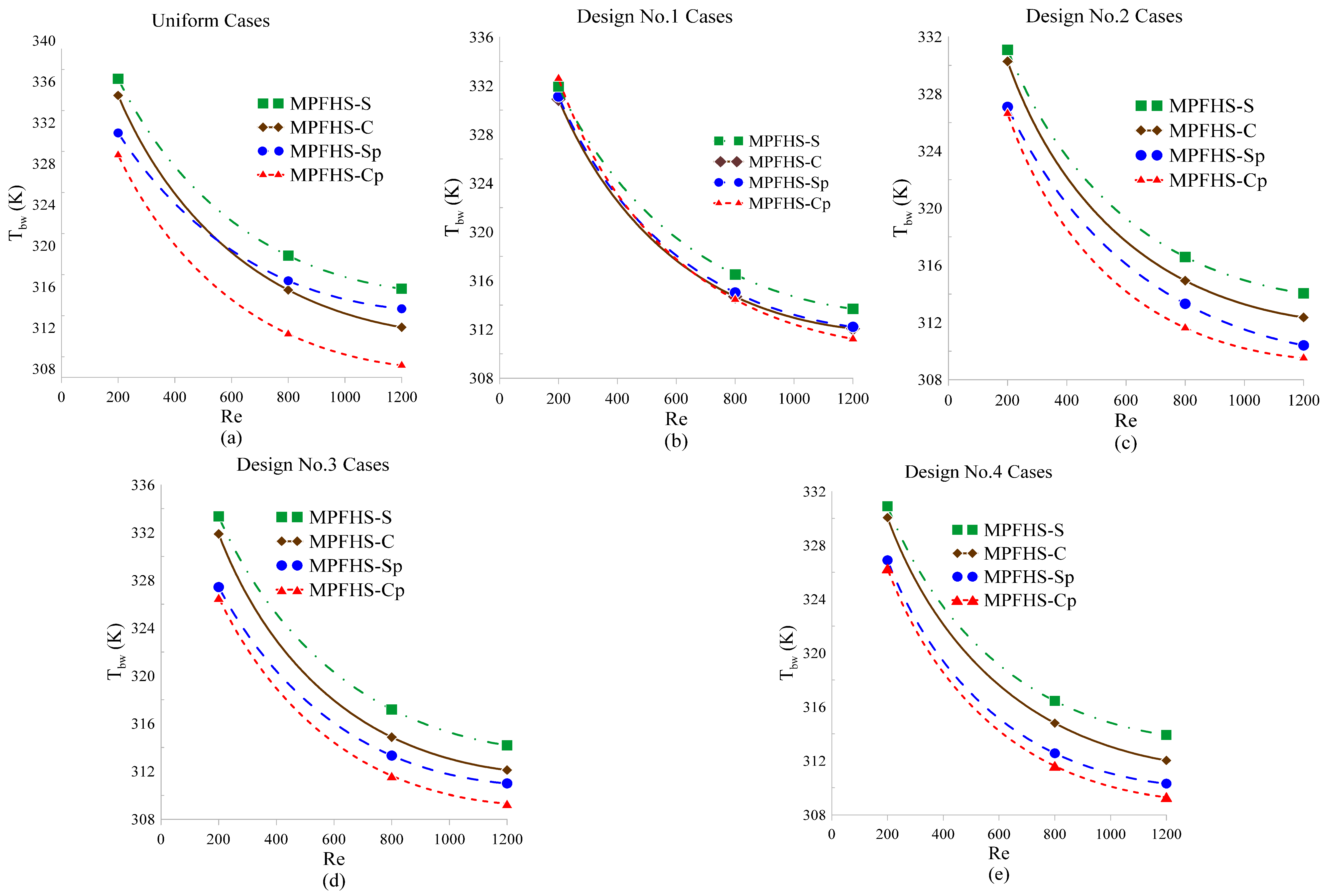
From the average base-plate temperature results shown in Figure 8, we observe that as the inlet Re increases, the temperature decreases across all cases. Furthermore, the Design #4 optimized by the LMM consistently yield the lowest temperatures among all design geometries, demonstrating the effectiveness of the hybrid fin-height arrangement. By combining the top-view temperature distributions (Figure 5) with the velocity distributions at the y = 4 mm cross-section (Figure 7), it can be seen that regions with higher flow velocity coincide with lower-temperature zones within the fin array. This confirms that higher flow velocities enhance heat removal.
As shown in Figure 8, the cooling enhancement provided by perforations is clearly evident. For a given fin-height configuration, circular fins exhibit better cooling performance than square fins, and all perforated-fin designs yield lower average base-plate temperatures, Tbw, than their corresponding solid-fin counterparts. It is also worth noting that increasing the flow velocity reduces the temperature differences among the design cases. For example, in the MPFHS-CP configuration, the temperature difference between the uniform design and Design #4 is 3.390 K at Re = 200, decreases to 0.606 K at Re = 800, and further diminishes to 0.022 K at Re = 1200. This indicates that, at high Reynolds numbers, the fin-height arrangement has only a minor influence on cooling performance. Instead, the fin geometry (square pin, circular pin, square-perforated pin, or circular-perforated pin) becomes the dominant factor governing the reduction in the average base-plate temperature.
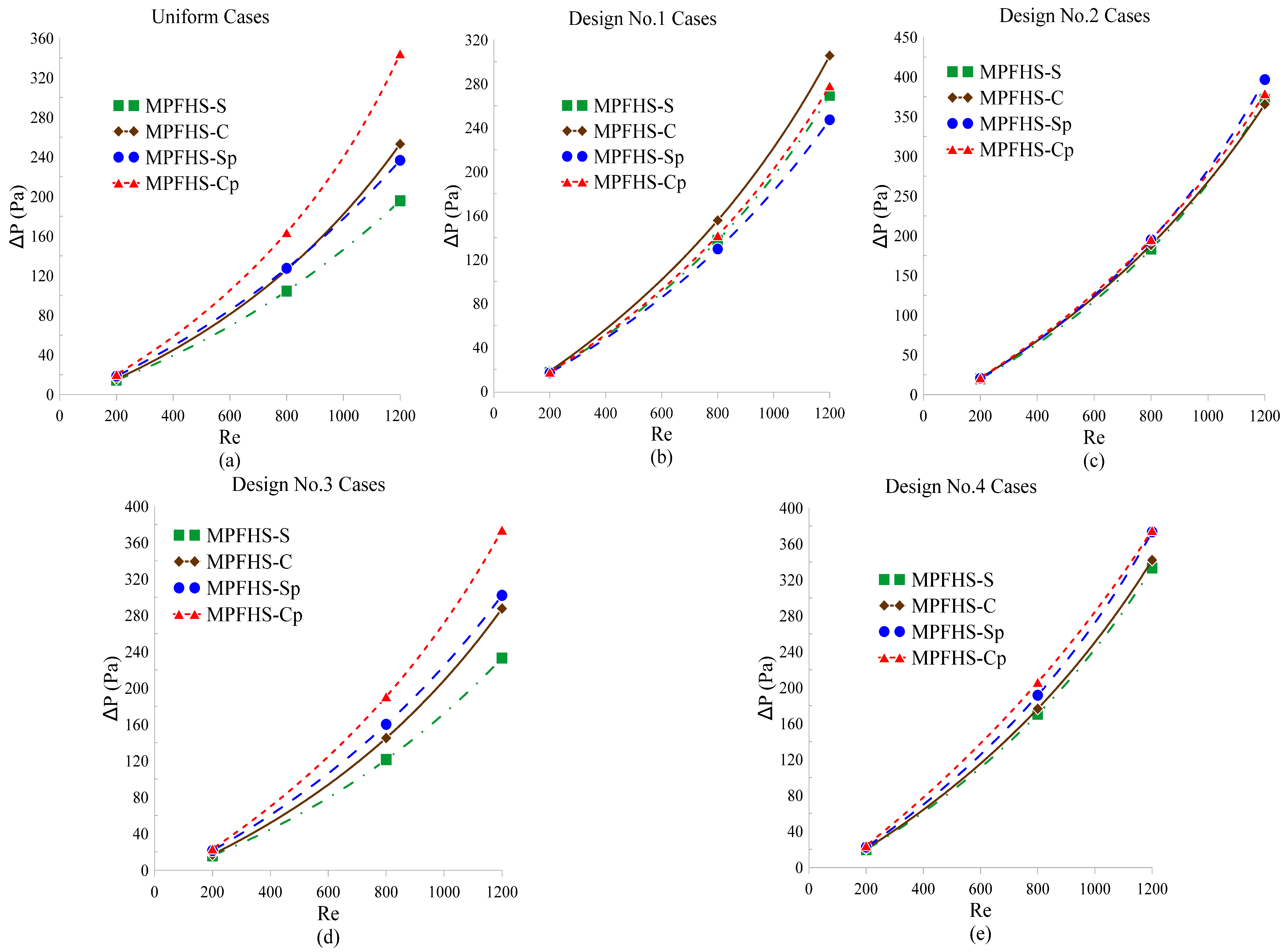
Figure 9 presents the pressure-drop performance of each design case under different Re; it can be observed that the pressure drop increases nonlinearly with the inlet Re. It is also learned that the perforated designs show higher pressure drops compared with the non-perforated ones. Based on the data from Table 3, Table 4 and Table 5, the pressure drop increases by an average of 14.8% at Re = 200, 10.7% at Re = 800, and 10.3% at Re = 1200 for perforated designs relative to non-perforated designs. Since the objective function of this study focuses on reducing the average base-plate temperature Tbw, pressure drop was not included in the optimization process. Therefore, the energy efficiency of each design case remains to be further evaluated.
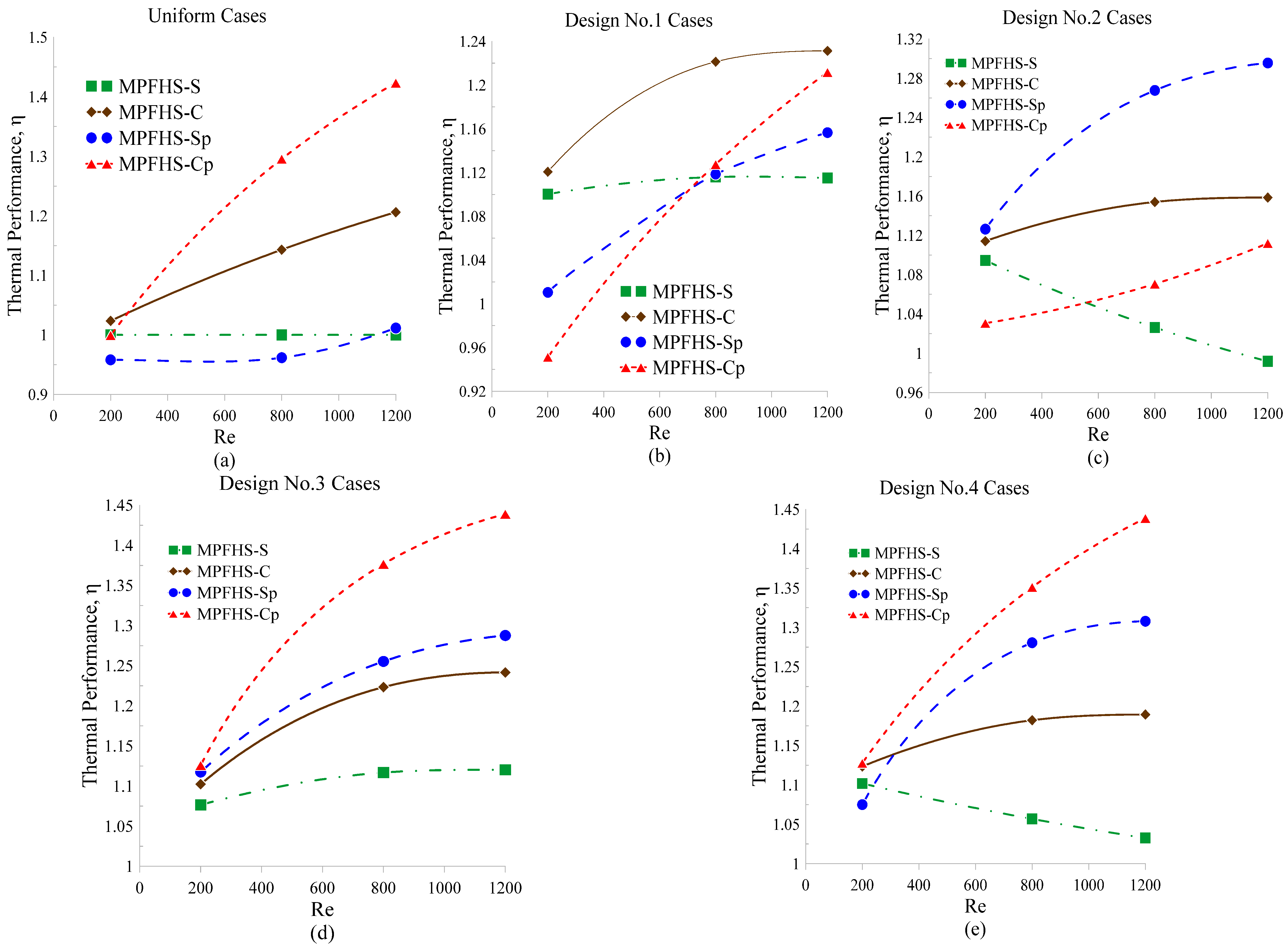
To evaluate the overall cooling efficiency of the MPFHS and balance the trade-off between pressure drop and temperature performance, a thermal performance factor η was introduced and calculated using Equation (11). In this study, the uniform MPFHS-S served as the baseline configuration (i.e., η = 1). Figure 10 presents the thermal performance factors of the various MPFHS design cases under different inlet Reynolds numbers. The results indicate that the uniform, Design #3, and Design #4 MPFHS-CP configurations exhibit particularly good performance at inlet Reynolds numbers of 800 and 1200, even though the thermal performance factor η was not included as an optimization objective.

6. Conclusions

Building upon the uniform, constant-step (Design #1), increasing-step (Design #2), and decreasing-step (Design #3) configurations proposed by Li and Jing [16], this study presents a systematic optimization analysis focusing specifically on the thermo-hydraulic performance of a hybrid-step fin-height distribution (Design #4) across varying inlet velocities. Both solid and perforated pin fins with square and cylindrical cross-sections are investigated at Reynolds numbers of Re = 200, 800, and 1200 using CFD-ACE+ coupled with the Levenberg–Marquardt method (LMM). The resulting thermo-fluid behavior is comprehensively evaluated in terms of temperature distribution, pressure-drop characteristics, and thermal performance factor.
  • Temperature distribution
The LMM optimization results indicate that Design #4 effectively reduces the average bottom-wall temperature (Tbw) across all flow velocities, significantly outperforming the traditional uniform and Design #1 MPFHSs.
  • In perforated designs (MPFHS-SP and MPFHS-CP), the perforations disrupt the thermal boundary layer and promote fluid flow in the wake regions of the fins. This eliminates heat accumulation, leading to further temperature reduction.
  • As the inlet Re increases, Tbw decreases across all designs. However, at higher velocities (Re = 800 to 1200), the temperature gap between different height distributions narrows. This suggests that at high flow rates, the fin geometry (specifically whether it is perforated) becomes the dominant factor in cooling, while the influence of height arrangement diminishes.
2.
Pressure-drop characteristics
As flow velocity increases, the pressure drop exhibits nonlinear growth.
  • Increasing Re from 200 to 800 results in an average pressure-drop increase of over eight times.
  • While perforated designs significantly lower temperatures, they introduce a 10–15% increase in pressure drop. This aligns with fluid dynamics theories regarding porosity and pore size in laminar flow regimes.
3.
Thermal performance factor (η)
To comprehensively assess the engineering practicality of each design, this study introduces the thermal performance factor (η) as an indicator balancing temperature reduction and pressure drop.
  • At low flow conditions (Re = 200), the optimized Design #4 yields the highest η value. Its perforated configuration achieves significant cooling benefits with only a modest pressure-drop penalty.
  • At moderate to high flow conditions (Re = 800 and 1200), the cylindrical-perforated configuration (MPFHS-CP) delivers the most outstanding overall performance, although its increased pressure drop must be considered.
  • As the flow velocity increases, Design #3 provides slightly less temperature reduction than Design #4; however, due to its lower pressure drop, it ultimately exhibits a more competitive thermal performance factor.
This study confirms that combining hybrid height-step distributions with perforated fin designs significantly enhances the performance of micro pin-fin heat sinks, making them highly promising for high-power electronic cooling applications with stringent thermal requirements. These results provide a theoretical foundation and concrete design guidelines for the advancement of microfluidic cooling technologies.

Author Contributions

Conceptualization, C.-H.H.; methodology, C.-H.H.; software, C.-P.H.; validation, C.-P.H.; formal analysis, C.-H.H.; investigation, C.-H.H. and C.-P.H.; resources, C.-H.H.; data curation, C.-P.H.; writing—original draft, C.-P.H.; writing—review and editing, C.-H.H.; supervision, C.-H.H.; project administration, C.-H.H.; funding acquisition, C.-H.H. All authors have read and agreed to the published version of the manuscript.

Funding

This work was supported in part through the National Science and Technology Council, Taiwan, grant number NSTC-115-2221-E-006-141-MY3.

Data Availability Statement

The original contributions presented in this study are included in the article. Further inquiries can be directed to the corresponding author.

Conflicts of Interest

The authors declare no conflict of interest.

Abbreviations

Abbase area (mm2)
Abwthe bottom surface area of the heat sink (mm2)
Acthe liquid interface area (mm2)
Acsthe solid–liquid interface area (mm2)
Asbase area of single fin (mm2)
Bidesign variable
Dpin fin diameter (mm)
Dhhydraulic diameter (mm)
ffriction factor
fenhancedfriction factor of the designed case
funiformfriction factor of the MPFHS-S uniform case
Hheight of the heat sink (mm)
Hswheight of the entrance (mm)
hheat transfer coefficient (W/m2-K)
hiheight of the ith fin (mm)
kthermal conductivity (W/m-K)
Llength of the heat sink (mm)
Linwidth of the entry (mm)
Mdynamic viscosity of water
NuNusselt number
NuenhancedNusselt number of the designed case
NuuniformNusselt number of the MPFHS-S uniform case
qbottom heat flux (W/m2)
qeffeffective heat flux (W/m2)
Rradius of perforation (mm)
ReReynolds number
Tavgaverage temperature at the solid–liquid interface (K)
Tbwaverage base temperature (K)
Tininlet temperature (K)
Toutoutlet temperature (K)
Tambient temperature (K)
uininlet velocity (m/s)
Vvolume of fins (mm3)
Vpvolume of the fin perforation (mm3)
Wwidth of heat sik (mm)
Wswthickness of fin (mm)
Greek symbols
ΨJacobian matrix
Δhheight difference (mm)
ΔPpressure drop (N/mm2)
ηcoefficient of thermal performance
δheight difference between two adjacent pin fins
Ωcomputational domain
εstopping criterion
ρdensity (kg/m3)
μweighting parameter
μ2dynamic viscosity (kg/m-s)

References

  1. Irfan, H.M.; Khan, M.M.; Shahzad, M.W. Hydro-thermal performance of an I-shaped pin fin microchannel heat sink with variable pin fin height, thickness and orientation. Int. Commun. Heat Mass Transf. 2025, 160, 108256. [Google Scholar] [CrossRef] [Scilit]
  2. Abuska, M.; Çorumlu, V. A comparative experimental thermal performance analysis of conical pin fin heat sink with staggered and modified staggered layout under forced convection. Therm. Sci. Eng. Prog. 2023, 37, 101560. [Google Scholar] [CrossRef] [Scilit]
  3. Al-Damook, A.; Kapur, N.; Summers, J.L.; Thompson, H.M. An experimental and computational investigation of thermal air flows through perforated pin heat sinks. Appl. Therm. Eng. 2015, 89, 365–376. [Google Scholar] [CrossRef] [Scilit]
  4. Al-Abboodi, N.K.F.; Khalaf, K.A.; Ridha, H.; Al-Azawy, M.G. Thermal and Flow Analysis of Different Shaped Pin Fins for Improved Heat Transfer Rate. Int. J. Heat Technol. 2022, 40, 201–210. [Google Scholar] [CrossRef] [Scilit]
  5. Alpha, N.A.; Aondover, I.H.; Kuhe, A. Experimental and numerical studies of the effect of perforation configuration on heat transfer enhancement of pin fins heat sink. Heat Transf. 2024, 53, 2525–2555. [Google Scholar] [CrossRef] [Scilit]
  6. Maji, A.; Bhanja, D.; Patowari, P.K. Numerical investigation on heat transfer enhancement of heat sink using perforated pin fins with inline and staggered arrangement. Appl. Therm. Eng. 2017, 125, 596–616. [Google Scholar] [CrossRef] [Scilit]
  7. Adhyaru, J.; Uma, M.; Praveena, V.; Sethuramalingam, P. Optimization of Thermal and Pressure Drop Performance in Circular Pin Fin Heat Sinks Using the TOPSIS Method. Energies 2024, 17, 6340. [Google Scholar] [CrossRef] [Scilit]
  8. Benouis, F.Z.; Amer, Y.O.; Arıcı, M.; Meziane, S. Designing and optimizing a novel heat sink for the enhancement of hydrothermal performances: Modelling and analysis using artificial neural network. Eng. Anal. Bound. Elem. 2023, 155, 766–778. [Google Scholar] [CrossRef] [Scilit]
  9. Al-Muhsen, N.F.O.; Al-Khafaji, O.R.S.; Ismail, F.B. Thermal Performance Optimization of Perforated Fins for Flat Plate Heat Sinks Using CFD Approach. Int. J. Heat Technol. 2023, 41, 1052–1062. [Google Scholar] [CrossRef] [Scilit]
  10. Yousfi, A.; Lahcene, B.; Alqurashi, F.; Djamel, S.; Teggar, M.; Laouer, A.; Arici, M.; Kchaou, M. Effect of Trenched Hemispherical Pin Fins on Cooling Performance of Heat Sink. Adv. Sci. Technol. Res. J. 2024, 18, 33–44. [Google Scholar] [CrossRef] [Scilit]
  11. Yan, Y.; Zhao, T.; He, Z.; Yang, Z.; Zhang, L. Numerical investigation on the characteristics of flow and heat transfer enhancement by micro pin-fin array heat sink with fin-shaped strips. Chem. Eng. Process. Process Intensif. 2021, 160, 108273. [Google Scholar] [CrossRef] [Scilit]
  12. Wen, M.Y.; Yeh, C.H. Forced convective performance of perforated circular pin-fin heat sinks. Heat Mass Transf. 2017, 53, 1713–1723. [Google Scholar] [CrossRef] [Scilit]
  13. Kore, S.S.; Yadav, R.; Chinchanikar, S.; Tipole, P.; Dhole, V. Experimental Investigations of Conical Perforations on the Thermal Performance of Cylindrical Pin Fin Heat Sink. Int. J. Ambient Energy 2022, 43, 3431–3442. [Google Scholar] [CrossRef] [Scilit]
  14. Maji, A.; Deshamukhya, T.; Choubey, G.; Choubey, A. Performance evaluation of perforated pin fin heat sink using particle swarm optimization and MCDM techniques. J. Therm. Anal. Calorim. 2022, 147, 5133–5150. [Google Scholar] [CrossRef] [Scilit]
  15. Bhandari, P.; Prajapati, Y.K. Thermal performance of open microchannel heat sink with variable pin fin height. Int. J. Therm. Sci. 2021, 159, 106609. [Google Scholar] [CrossRef] [Scilit]
  16. Li, H.; Jing, D. Hydraulic and thermal performances of micro pin fin heat sink with increasing pin fin height. Case Stud. Therm. Eng. 2024, 53, 103912. [Google Scholar] [CrossRef] [Scilit]
  17. Hossain, M.I.; Chowdhury, M.S.H.; Ahmed, S.S.U.; Hamja, A.; Siddique, I.J. Forced convective heat transfer over twisted and perforated forked pin fin heat sink: A numerical study. Int. J. Therm. Sci. 2025, 211, 109719. [Google Scholar] [CrossRef] [Scilit]
  18. Muralikrishna, Y.; Kumar, M.M.J.; Aravind, B.; Sahu, M.K. Comparative studies on performance of plain, perforated, threaded, and threaded–perforated pin fin: A numerical approach. Heat Transf. 2023, 52, 3333–3352. [Google Scholar] [CrossRef] [Scilit]
  19. Marquardt, D.W. An algorithm for least-squares estimation of nonlinear parameters. J. Soc. Ind. Appl. Math. 1963, 11, 431–441. [Google Scholar] [CrossRef] [Scilit]
  20. Huang, C.-H.; Liu, L.W. Optimal Position and Perforated Radius of Punched Vortex Generators for Heat Sink. Case Stud. Therm. Eng. 2022, 32, 101916. [Google Scholar] [CrossRef] [Scilit]
  21. Huang, C.-H.; Chung, K.J. Optimal Design of Perforated Fins for LED Radial Heat Sink Module with Varied Hole Numbers and Sizes. Appl. Therm. Eng. 2024, 242, 122451. [Google Scholar] [CrossRef] [Scilit]
  22. Huang, C.-H.; Xu, E.H. Optimization of Natural Convection Heat Sinks with Inverted Trapezoidal Fins and Elliptical Perforations. Int. J. Therm. Sci. 2026, 222, 110581. [Google Scholar] [CrossRef] [Scilit]
  23. ESI-CFD Inc. CFD-ACE+ User’s Manual; ESI-CFD Inc.: Paris, France, 2026. [Google Scholar]
Figure 1. The computational domain of MPFHS.
Mathematics 14 03227 g001
Figure 2. The (a) MPFHS-S, (b) MPFHS-C, (c) MPFHS-Sp and (d) MPFHS-Cp fin configurations for the Design #4 fin-height arrangement.
Mathematics 14 03227 g002
Figure 3. A graphical representation of calculating the approximate volume of each perforation.
Mathematics 14 03227 g003
Figure 4. The (a) top and (b) front views of the MPFHS-Sp and MPFHS-Cp.
Mathematics 14 03227 g004
Figure 5. The top-view temperature distributions for MPFHS-Cp with (a) uniform, (b) Design #1, (c) Design #2, (d) Design #3 and (e) Design #4 fin heights at Re = 200.
Mathematics 14 03227 g005
Figure 6. The fin-height distributions for (a) Design #1, (b) Design #2, (c) Design #3 and (d) Design #4 MPFHSs.
Mathematics 14 03227 g006
Figure 7. The velocity distributions for MPFHS-Cp with (a) uniform, (b) Design #1, (c) Design #2, (d) Design #3 and (e) Design #4 fin heights at Re = 200 and y = 4 mm.
Mathematics 14 03227 g007
Figure 8. The Tbw of MPFHSs with (a) uniform, (b) Design #1, (c) Design #2, (d) Design #3 and (e) Design #4 fin heights at various Re numbers.
Mathematics 14 03227 g008
Figure 9. The ΔP of MPFHSs with (a) uniform, (b) Design #1, (c) Design #2, (d) Design #3 and (e) Design #4 fin heights at various Re numbers.
Mathematics 14 03227 g009
Figure 10. The η of MPFHSs with (a) uniform, (b) Design #1, (c) Design #2, (d) Design #3 and (e) Design #4 fin heights at various Re numbers.
Mathematics 14 03227 g010
Table 1. The physical properties of copper and water.
PropertyCopper [16]Water [15]
Density
ρ(T), kg/m3
8960765.33 + 1.8142T − 0.0035T2
Specific Heat
Cp(T), J/kg-K
38528,070 − 281.7T + 1.25T2 − (2.48 × 10⁻³)T3 + (1.857 × 10⁻⁶)T4
Thermal Conductivity k(T), W/m-K387.6−0.5752 + (6.397 × 10⁻³)T − (8.151 × 10⁻⁶)T2
Dynamic Viscosity
μ(T), kg/m-s
N/A9.67 × 10−2 − (8.207 × 10⁻⁴)T +
(2.344 × 10⁻⁶)T2 − (2.244 × 10⁻⁹)T3
Table 2. The results of the grid independent tests.
Grid NumbersTbw (K)ΔP (Pa)Time (s)
584,000337.566314.2014427
1,068,000337.298214.3429937
1,765,000337.171414.40512005
2,729,000337.099614.43593547
4,743,000337.044914.47508927
Table 3. The computational results at Re = 200.
Design CasesVariables, mmTbw, KNuΔP, N/ m 2 fηIterations
MPFHS-S uniformN/A337.09967.716014.43601.24691N/A
MPFHS-S Design #1Δh = 0.0909331.95449.022317.32361.49631.1003N/A
MPFHS-S Design #2δ1 = 0.0210, δ2 = 0331.09339.382519.79431.70981.0945N/A
MPFHS-S Design #3δ1 = 0, δ2 = 0.0119333.35048.598016.00651.38261.0765N/A
MPFHS-S Design #4δ1 = 0.0253, δ2 = 0.00203330.90959.420219.63461.69601.10183
MPFHS-C uniformN/A335.47108.097315.55761.34381.0235N/A
MPFHS-C Design #1Δh = 0.0909330.90349.371218.36841.58661.1207N/A
MPFHS-C Design #2δ1 = 0.0210, δ2 = 0330.27909.737020.97561.81181.1141N/A
MPFHS-C Design #3δ1 = 0, δ2 = 0.0119331.88359.025717.24901.48991.1023N/A
MPFHS-C Design #4δ1 = 0.0250, δ2 = 0.00217330.06859.761420.61221.78041.12343
MPFHS-Sp uniformR = 0.245331.81348.031018.50191.59810.9581N/A
MPFHS-Sp Design #1Δh = 0.1252, R = 0.245331.11728.205316.82731.45341.0104N/A
MPFHS-Sp Design #2δ1 = 0.0139, δ2 = 0.0085, R = 0.245327.090610.073022.48071.94181.1263N/A
MPFHS-Sp Design #3δ1 = 0, δ2 = 0.0163, R = 0.245327.43079.843521.48031.85531.1175N/A
MPFHS-Sp Design #4δ1 = 0.0076, δ2 = 0.012, R = 0.245326.902610.095322.49501.94301.12857
MPFHS-Cp uniformR = 0.245329.66988.639420.30381.75370.9993N/A
MPFHS-Cp Design #1Δh = 0.1277, R = 0.245332.59837.815317.42851.50540.9512N/A
MPFHS-Cp Design #2δ1 = 0.0139, δ2 = 0.0085, R = 0.245326.63169.062821.37051.84591.0306N/A
MPFHS-Cp Design #3δ1 = 0, δ2 = 0.0163, R = 0.245326.551810.189723.29562.01221.1259N/A
MPFHS-Cp Design #4δ1 = 0.0073, δ2 = 0.0122, R = 0.245326.279910.335824.19772.09011.12767
Table 4. The computational results at Re = 800.
Design CasesVariables, mmTbw, KNuΔP, N/ m 2 fηIterations
MPFHS-S uniformN/A319.852514.7101104.41100.56371N/A
MPFHS-S Design #1Δh = 0.0909316.513117.5597137.56030.74261.1159N/A
MPFHS-S Design #2δ1 = 0.0210, δ2 = 0316.596118.2142183.40020.99021.0262N/A
MPFHS-S Design #3δ1 = 0, δ2 = 0.0119317.186217.2738121.39400.65541.1168N/A
MPFHS-S Design #4δ1 = 0.0212, δ2 = 0.00488316.446018.3032170.37470.91981.05683
MPFHS-C uniformN/A316.510817.8944125.83460.67941.1431N/A
MPFHS-C Design #1Δh = 0.0909314.690220.5233155.63410.84021.2213N/A
MPFHS-C Design #2δ1 = 0.0210, δ2 = 0314.930120.6723188.54891.01791.1540N/A
MPFHS-C Design #3δ1 = 0, δ2 = 0.0119314.860520.0841145.17100.78371.2233N/A
MPFHS-C Design #4δ1 = 0.0198, δ2 = 0.00512314.601020.7186176.57270.95321.18224
MPFHS-Sp uniformR = 0.245317.405615.1211127.49140.68830.9617N/A
MPFHS-Sp Design #1Δh = 0.1252, R = 0.245315.031617.6826129.58730.69961.1185N/A
MPFHS-Sp Design #2δ1 = 0.0139, δ2 = 0.0085, R = 0.245313.312722.8498192.16271.03741.2676N/A
MPFHS-Sp Design #3δ1 = 0, δ2 = 0.0163, R = 0.245313.315621.2986160.22500.86501.2553N/A
MPFHS-Sp Design #4δ1 = 0.0112, δ2 = 0.010, R = 0.245312.561523.0619191.57811.03421.28066
MPFHS-Cp uniformR = 0.245312.223122.1328163.57200.88311.2955N/A
MPFHS-Cp Design #1Δh = 0.1277, R = 0.245314.457518.3719141.88840.76601.1275N/A
MPFHS-Cp Design #2δ1 = 0.0139, δ2 = 0.0085, R = 0.245311.625020.0874216.68971.16981.0706N/A
MPFHS-Cp Design #3δ1 = 0, δ2 = 0.0163, R = 0.245311.624124.7566190.73961.02971.3767N/A
MPFHS-Cp Design #4δ1 = 0.0076, δ2 = 0.0120, R = 0.245311.617024.9314206.12411.11281.35117
Table 5. The computational results at Re = 1200.
Design CasesVariables, mmTbw, KNuΔP, N/ m 2 fηIterations
MPFHS-S uniformN/A316.632717.7049195.62790.46941N/A
MPFHS-S Design #1Δh = 0.0909313.687421.9669269.45790.64651.1151N/A
MPFHS-S Design #2δ1 = 0.0210, δ2 = 0314.048221.7484371.62740.89170.9918N/A
MPFHS-S Design #3δ1 = 0, δ2 = 0.0119314.171421.0279233.07980.55931.1203N/A
MPFHS-S Design #4δ1 = 0.0192, δ2 = 0.00544313.625121.9855333.32090.79981.03264
MPFHS-C uniformN/A312.875323.2670253.02510.60711.2061N/A
MPFHS-C Design #1Δh = 0.0909312.068625.2968305.61970.73331.2313N/A
MPFHS-C Design #2δ1 = 0.0210, δ2 = 0312.360325.2638365.54300.87711.1585N/A
MPFHS-C Design #3δ1 = 0, δ2 = 0.0119312.103624.9955287.59730.69001.2416N/A
MPFHS-C Design #4δ1 = 0.0188, δ2 = 0.00565312.028925.3709342.11550.82081.18944
MPFHS-Sp uniformR = 0.245314.677119.0793236.55240.56761.0115N/A
MPFHS-Sp Design #1Δh = 0.1252, R = 0.245312.213422.1368247.19730.59311.1565N/A
MPFHS-Sp Design #2δ1 = 0.0139, δ2 = 0.0085, R = 0.245310.402328.4841374.72830.89911.2955N/A
MPFHS-Sp Design #3δ1 = 0, δ2 = 0.0163, R = 0.245310.983026.3499302.08590.72481.2876N/A
MPFHS-Sp Design #4δ1 = 0.0112, δ2 = 0.010, R = 0.245310.308028.7244373.44620.89601.30797
MPFHS-Cp uniformR = 0.245309.164330.4235344.29400.82611.4232N/A
MPFHS-Cp Design #1Δh = 0.1277, R = 0.245311.226524.1244278.14280.66731.2117N/A
MPFHS-Cp Design #2δ1 = 0.0139, δ2 = 0.0085, R = 0.245309.517325.2235411.40360.98711.1120N/A
MPFHS-Cp Design #3δ1 = 0, δ2 = 0.0163, R = 0.245309.316631.6227374.04970.89751.4390N/A
MPFHS-Cp Design #4δ1 = 0.00023, δ2 = 0.0162, R = 0.245309.142531.6459375.17890.90021.43877
Disclaimer/Publisher’s Note: The statements, opinions and data contained in all publications are solely those of the individual author(s) and contributor(s) and not of MDPI and/or the editor(s). MDPI and/or the editor(s) disclaim responsibility for any injury to people or property resulting from any ideas, methods, instructions or products referred to in the content.