1. Introduction
Modern industry increasingly demands low-noise and lightweight equipment. In response, vibration problems have drawn extensive research attention from scholars and engineers [
1,
2,
3]. In industrial practice, dynamic vibration absorption, vibration isolation, and damping enhancement are prevalent technical approaches for vibration control [
4]. Among these, dynamic vibration absorbers (DVAs) are frequently employed in engineering practice to suppress vibration due to their distinct advantages, including high reliability, low maintenance costs, and ease of installation [
5,
6].
The concept of the DVA was first proposed by Frahm in his patent filed in 1909 [
7]. Over the past 100 years, numerous scholars have conducted extensive research on the key issues encountered in its practical engineering applications [
8,
9,
10]. In terms of parameter design, Brennan et al. [
11] focused on controlling global structural vibration using a tunable vibration neutralizer, deriving an expression for the optimal ratio between the neutralizer mass and the structural modal mass. To address the influence of locations on vibration suppression, Lee et al. [
12] employed a genetic algorithm to optimize the locations of pendulum-type DVAs. Recently, addressing space-constrained vibration control, Li et al. [
13] ingeniously leveraged the inertial effect of a tuned inerter eddy current damper to amplify damping and inertance, developing a compact absorber which was successfully applied for civil seismic protection. Furthermore, nonlinear dynamic vibration absorption technologies have also garnered considerable attention [
14,
15]. The explored directions include nonlinear metamaterials [
16,
17,
18], dual quasi-zero-stiffness absorbers [
19], and coupled modeling of nonlinear absorbers for broadband vibration suppression [
20,
21].
Current DVA designs predominantly focus on the suppression of vibration subjected to unidirectional harmonic excitations [
22,
23,
24]. However, in engineering practice, mechanical systems and structures are frequently subjected to excitations that exhibit multi-directional characteristics. For instance, shipboard equipment such as water pumps, motors, and reciprocating pumps serves as multiple excitation sources. Consequently, the vibration modes of the structure are often dominated by the coupling effects of these sources, resulting in complex, multidimensional vibration behaviors. Therefore, designing a DVA with low directional sensitivity is of great significance for engineering applications [
25].
Relevant research has been conducted to address multi-directional vibration suppression [
26]. With the continuous evolution of metamaterial mechanics [
27,
28,
29,
30,
31], Liu et al. [
32] utilized the local resonance bandgap effect to design a multi-dimensional quasi-zero-stiffness metamaterial for multi-directional isolation. Zou et al. [
33] proposed a piezoelectric smart platform achieving multi-directional isolation through active control methods. In addition, Shi et al. [
34] employed the multi-directional characteristics of metal rubber to design a secondary isolation system for random vibration. Although these studies address multi-directional suppression through different mechanisms, none of these studies treat the mass of the auxiliary rigid support structures as a design variable. The lightweighting of these supports is therefore overlooked.
To address the challenges of multidirectional vibration suppression and the excessive added mass of conventional absorbers in engineering practice, this study proposes a lightweight design method for isotropic DVAs based on an elastic shell architecture. This method overcomes the conventional limitation of treating the shell as a rigid body. This study makes two contributions. First, an isotropic dynamic model coupling spring and shell stiffnesses is established. This model reveals a critical failure mode: the isotropy degrades during the lightweight design process due to shear deformation. Second, to address this issue, a collaborative design framework is constructed. This framework employs topology optimization for configuration design and introduces a Kriging surrogate model [
35,
36,
37] to optimize the reconstructed parameters. By constraining the shear stiffness, the framework successfully achieves mass reduction of the shell while preserving the overall isotropy of the absorber. Finally, the feasibility and effectiveness of this design method are verified through simulations and experiments.
The remainder of this paper is organized as follows.
Section 2 establishes the isotropic dynamic model of coupling spring and shell stiffnesses, providing the theoretical basis for the lightweight design.
Section 3 presents a systematic framework for collaborative design, integrating topology and parameter optimization. This framework encompasses shear-resistant topology optimization of the shell, parameter optimization, and the spring design method.
Section 4 demonstrates the complete lightweight design process and simulation verification, using a 50 Hz DVA as a case study.
Section 5 further validates the isotropic characteristics of the proposed method through prototype experiments. Finally,
Section 6 summarizes the conclusions of this study.
2. Isotropic Dynamic Model of Coupling Spring and Shell Stiffnesses for Natural Frequency Calculation
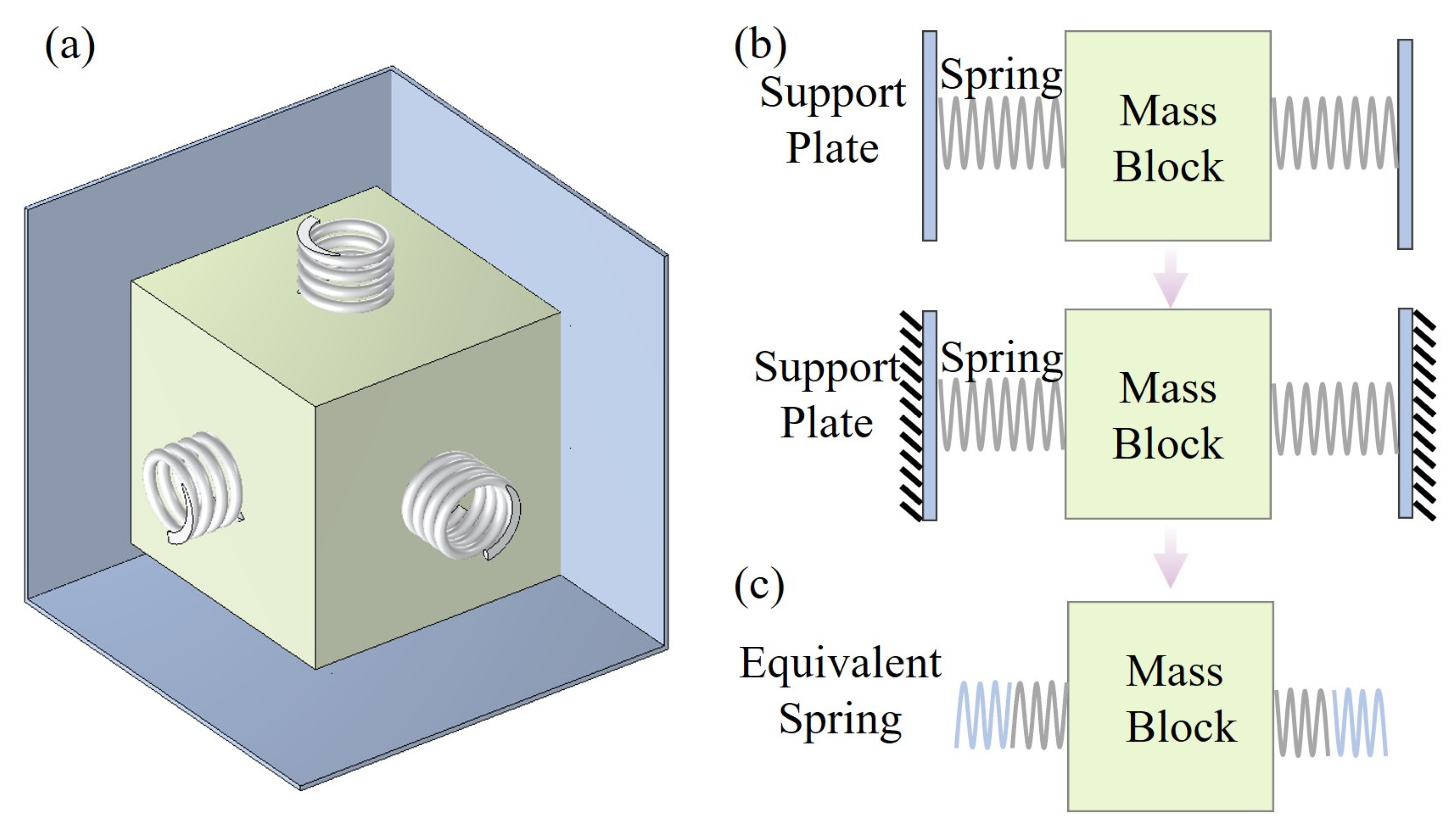
The spring-mass block type DVA is simple to design. This study proposes an isotropic configuration of a rigid shell, as shown in
Figure 1a. This absorber consists of six panels of a cubic shell, six springs, and a mass block. The same spring components are uniformly distributed on each surface of the mass block. This arrangement produces an absorber structure with isotropic mechanical properties. Furthermore, in practical applications, the spring and shell components undergo small deformations. Accordingly, linear elasticity is considered in this study. In conventional DVA designs, the shell panels are generally assumed to be rigid. As shown in
Figure 1b, taking a pair of one-way spring components as an example, this rigid shell theoretically ensures the isotropic mechanical characteristics of the structure. On this basis, to accurately calculate the natural frequency of the system, both the axial stiffness and shear stiffness of the springs must be taken into account. The calculation formulas for shear stiffness and axial stiffness [
38] are given as Equations (1) and (2):
where
and
denote the shear stiffness and axial stiffness of the spring, respectively.
represents the effective height of the spring,
is the wire diameter,
is the Young’s modulus of the spring material,
v is the Poisson’s ratio,
is the mean coil diameter, and
n indicates the number of active coils. In addition,
represents the axial load applied to the spring. Since this study considers the spring in its free state, a value approaching zero is assigned to
when calculating the shear stiffness.
In Equation (1), the parameter
is defined as
where
and
denote the equivalent shear stiffness and equivalent bending stiffness of the spring, respectively. They are calculated as follows:
It should be noted that all formulas in Equations (1)–(5) assume that the spring operates within the linear elastic range. In addition, the shear stiffness formulas in Equations (1) and (3)–(5) further assume that the upper and lower end surfaces of the spring remain parallel during lateral loading.
Metal springs inherently possess very low damping. Therefore, assuming the damping effect is negligible, the equation of motion for the system can be expressed as
Considering that the springs are mounted on the surfaces of the cubic mass block, the total stiffness is derived from 4 springs acting in shear and 2 springs acting in the axial direction. Using the stiffness components from Equations (1) and (2), the equivalent stiffness of the system is derived. Thus, the natural frequency derived from Equation (6) is expressed as
Given that 50 Hz is a prevalent vibration frequency for mechanical equipment in engineering applications, a DVA with a target natural frequency of 50 Hz and a 4 kg mass block is selected as a case study. Here, the conventional rigid shell design illustrated in
Figure 1b is adopted. The parameters of the spring are as follows: Young’s modulus
, Poisson’s ratio
, density
, wire diameter
, mean coil diameter
, effective height
and effective number of coils
. Aluminum is selected as the shell material, with Young’s modulus
, Poisson’s ratio
, and density
. In the simulation model, a 160 mm internal cubic space is reserved to install the spring and a 108 mm long cube mass.
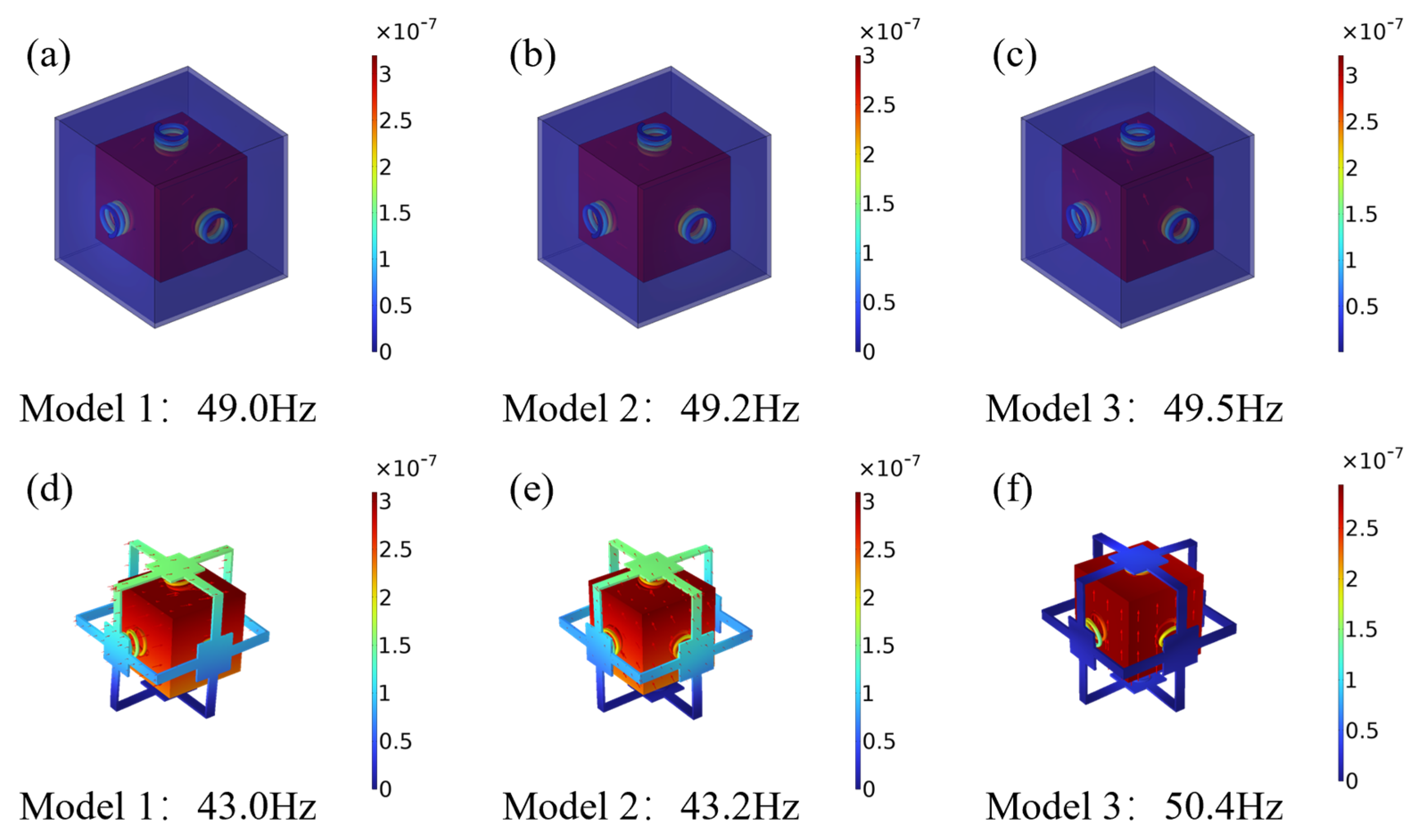
Additionally, fixed constraints are applied to the four corners of the bottom surface in consideration of common installation scenarios. To guarantee effective vibration suppression at the target frequency, the natural frequencies of the three translational modes need to be controlled within a 1 Hz deviation from 50 Hz. Under this stiffness criterion, the shell thickness must reach 3 mm, with the corresponding first three translational mode shapes illustrated in
Figure 2a–c. This design results in a shell mass of up to 1.29 kg, accounting for 32.3% of the mass block.
In conventional designs, the thick shell guarantees rigidity, meaning isotropy failure is not an issue. However, this high mass ratio severely constrains the lightweight design of vibration absorbers. To reduce the weight, the shell must be thinned, which invalidates the rigid-body assumption. Therefore, this study proposes a design strategy in which the shell is considered as an elastic component possessing both axial and shear stiffnesses. The simplified mechanical model is illustrated in
Figure 1c, using a unidirectional spring pair as an example. On this basis, an isotropic dynamic model of coupling spring and shell stiffnesses is established. Specifically, based on force equilibrium, these two components are subjected to the same internal force, while their total deformation is the superposition of their individual deformations. Dividing the total displacement by the shared force yields the standard series stiffness relationship. Consequently, the expressions for the equivalent axial stiffness and equivalent shear stiffness of the system are derived as follows:
where
and
denote the equivalent axial stiffness and equivalent shear stiffness of the series stiffness system, respectively. Additionally,
denotes the shell axial stiffness and
represents the shear stiffness. Based on the stiffness superposition comprising four equivalent shear components and two equivalent axial components for the translational modes of the mass block, the differential equation of motion is established as Equation (10).
Consequently, based on the isotropic dynamic model of coupling spring and shell stiffnesses, the natural frequency calculation formula is derived as follows:
During the lightweight design, the in-plane shear stiffness of individual panels may become insufficient. When this occurs, the installation boundary conditions significantly compromise the isotropic characteristics of the absorber. Specifically, the absorber is typically installed by fixing the four corners of the bottom surface. This results in the constraint stiffness of the bottom being significantly higher than that of the side surfaces, thereby introducing directional stiffness discrepancies. Consequently, the stiffness parameters ( and ) of the six faces are no longer identical, and Equation (11) will no longer be applicable.
To verify this, the lightweight “cross-shaped” shell scheme shown in
Figure 2d–f is examined as a case study. In this configuration, fixed constraints are applied to the four ends of the bottom cross structure, and the geometric parameters are set to a wall thickness of 3 mm and a rib width of 13 mm. Additionally, a central square area with a side length of 50 mm is reserved to accommodate the springs. To match the target frequency, the effective number of coils
n is adjusted to 3, while the remaining parameters are kept consistent with the conventional rigid shell scheme. The results indicate that although the shell mass is successfully reduced to 0.26 kg, the in-plane shear stiffness of the side panels is severely insufficient. Consequently, the structure fails to effectively counteract the anisotropy induced by the boundary constraints. This produces a frequency spread of 7.4 Hz among the three translational mode shapes. Such a large spread is unacceptable in practical applications.
To address this issue, this study establishes a targeted topology optimization model aiming to enhance the shear resistance of the initial configuration. This ensures that while achieving lightweight design, the impact of installation boundary conditions on the isotropic mechanical characteristics is minimized.
3. Lightweight Design Method for Isotropic Dynamic Vibration Absorbers
Topology optimization is an advanced numerical design method within the field of structural optimization [
39]. It uses algorithms to decide the retention and removal of material, achieving an optimal material distribution [
40]. This results in innovative structures that are both high-performing and resource-efficient. Although topology optimization effectively reveals optimal load transmission paths and material distribution patterns, the resulting irregular curvilinear boundaries often lead to complex machining processes and increased fabrication difficulty. To simultaneously achieve high mechanical performance and engineering manufacturability, geometric features are extracted from the topology optimization results for parametric reconstruction. This process serves as the foundation for subsequent parameter optimization design.
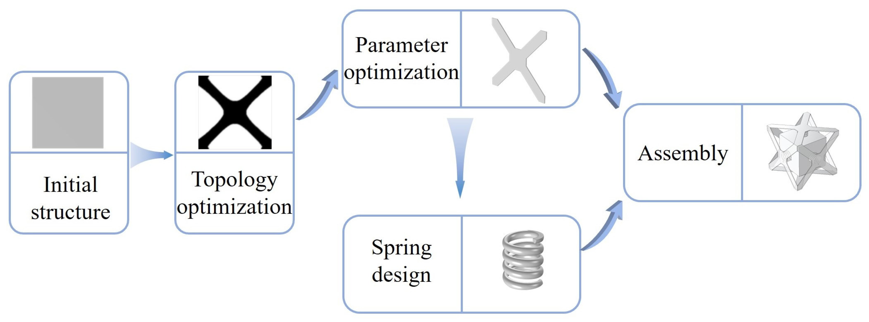
This study establishes an efficient multi-stage design framework, as shown in
Figure 3. First, a topology optimization model targeting shear resistance is established. By focusing on the design of a single shell panel, the computational scale is significantly reduced. Next, a Kriging surrogate model is introduced for parameter optimization, with the displacement difference set as a constraint. This approach effectively reduces the number of simulation iterations, ensuring high computational efficiency. Consequently, the spring parameters are determined by utilizing the shear and axial stiffness of the optimized shell to perform an inverse derivation based on the isotropic dynamic model of coupling spring and shell stiffnesses. Finally, the assembly of the ‘shell–spring–mass block’ system is completed.
3.1. Shear-Resistant Topology Optimization of the Shell Panel
Over the past few decades, topology optimization has evolved significantly, resulting in various mature algorithms. Representative approaches include Solid Isotropic Material with Penalization (SIMP), the Level Set Method, and Evolutionary Structural Optimization [
41]. Among these, the SIMP method is adopted in this study due to its simplicity, strong robustness, and high computational efficiency [
42,
43]. The fundamental principle of SIMP is to establish a relationship between the elastic modulus and element density by introducing an interpolation function and a penalization mechanism. Specifically, this relationship is defined by the following interpolation formula:
where the design variable
describes the material distribution, and
serves as the penalization factor, typically set to 3. The parameter
is a small value approaching zero, significantly lower than the elastic modulus of the solid material
, introduced to prevent singularity in the stiffness matrix. Furthermore, to eliminate checkerboard patterns and enhance boundary discreteness, the design variables are first filtered using a Helmholtz filter [
44], as defined in Equation (13), and subsequently projected via a tanh function [
45], as shown in Equation (14).
where
denotes the filtered design variable,
represents the projected design variable, and
= 8 specifies the projection slope.
Based on this optimization algorithm, this section conducts the lightweight design of the shell structure of the DVA. Given the macroscopic cubic configuration of the absorber, the design space can be effectively reduced by leveraging structural symmetry. Consequently, a global analysis of the entire shell is unnecessary. Instead, a single square panel is extracted to serve as the independent design domain. The final hexahedral shell, possessing isotropic characteristics, is constructed by assembling six of these optimized panels.
When the absorber experiences lateral vibration, the shell panels primarily undergo shear deformation. As previously analyzed, if the panel shear stiffness is insufficient, the structural isotropy is severely destroyed. Accordingly, the corresponding mathematical model can be expressed as
where
denotes the total strain energy of the structure.
represents the spatial coordinate vector in the design domain.
represents the volume constraint imposed on the design domain. The condition
implies that the global displacement within
is zero, representing the application of fixed constraints. Additionally, the constraints
are used to impose periodic boundary conditions and limit the plate to only undergo shear deformation.
The homogenization theory based on strain energy is introduced to clarify the objective function. The numerical procedure of the homogenization relies on the equivalence between the energy of the homogenized media,
WH, and the total strain energy,
W, stored in the unit cell induced by the prescribed test strains
ε as
where
denotes the equivalent volume of the plate, and
is homogenized stiffness matrix.
is induced strain field by the prescribed test strains
ε.
is the stiffness matrix of the basic material.
Using , which is realized by the constraints in the optimization model, the total strain energy W can represent the shear modulus G. Thus, this approach effectively guides the topology optimization algorithm to generate a structural configuration with optimal shear resistance.
As shown in
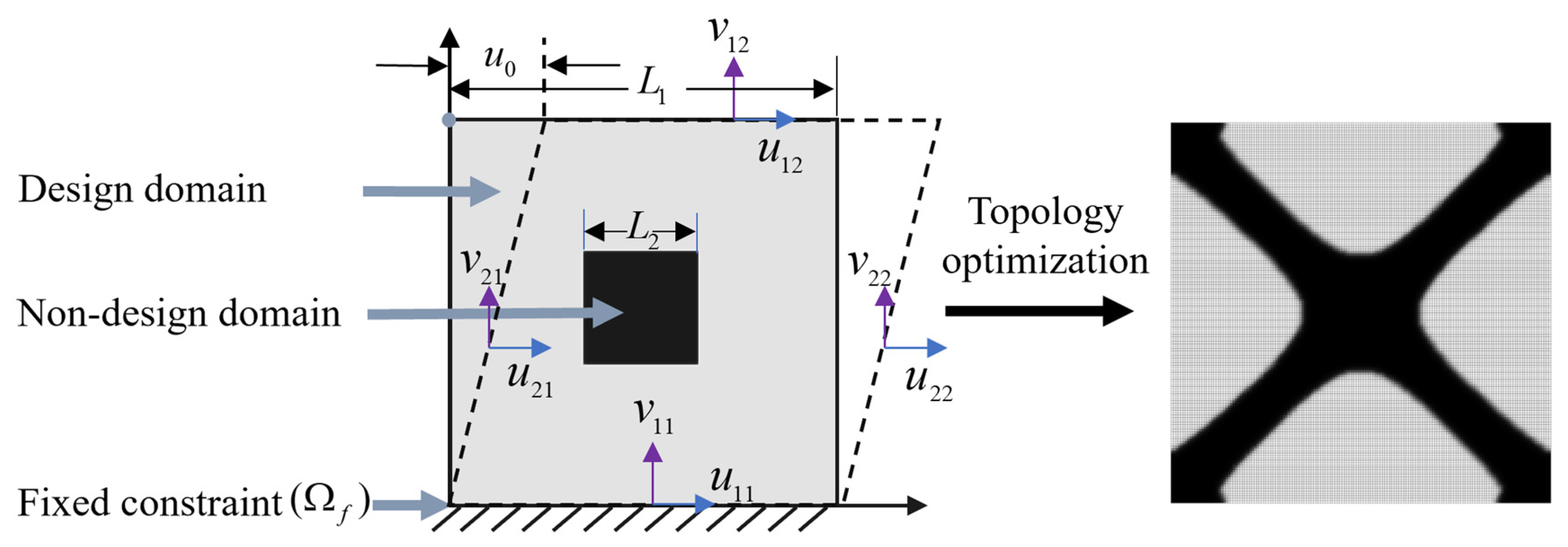
Figure 4 (left), the geometric configuration of the topology optimization model is defined as a square plate with a side length of
mm. To reserve the installation position for the spring components, a central square area with a side length of
mm is set as the non-design domain, while the remaining area serves as the design domain. The constraints and loading conditions for the optimization process are established as follows: (1) A fixed constraint is imposed on the bottom edge of the plate. (2) To simulate the shear condition, apply an X-direction displacement load with an amplitude of
to the top-left vertex, and restrict the entire structure to only undergo shear deformation. (3) A material volume fraction constraint is enforced.
The final optimized configuration is presented in
Figure 4 (right), revealing that the material distribution exhibits distinct X-shaped topological characteristics.
3.2. Parameter Optimization of the Elastic Shell Structure
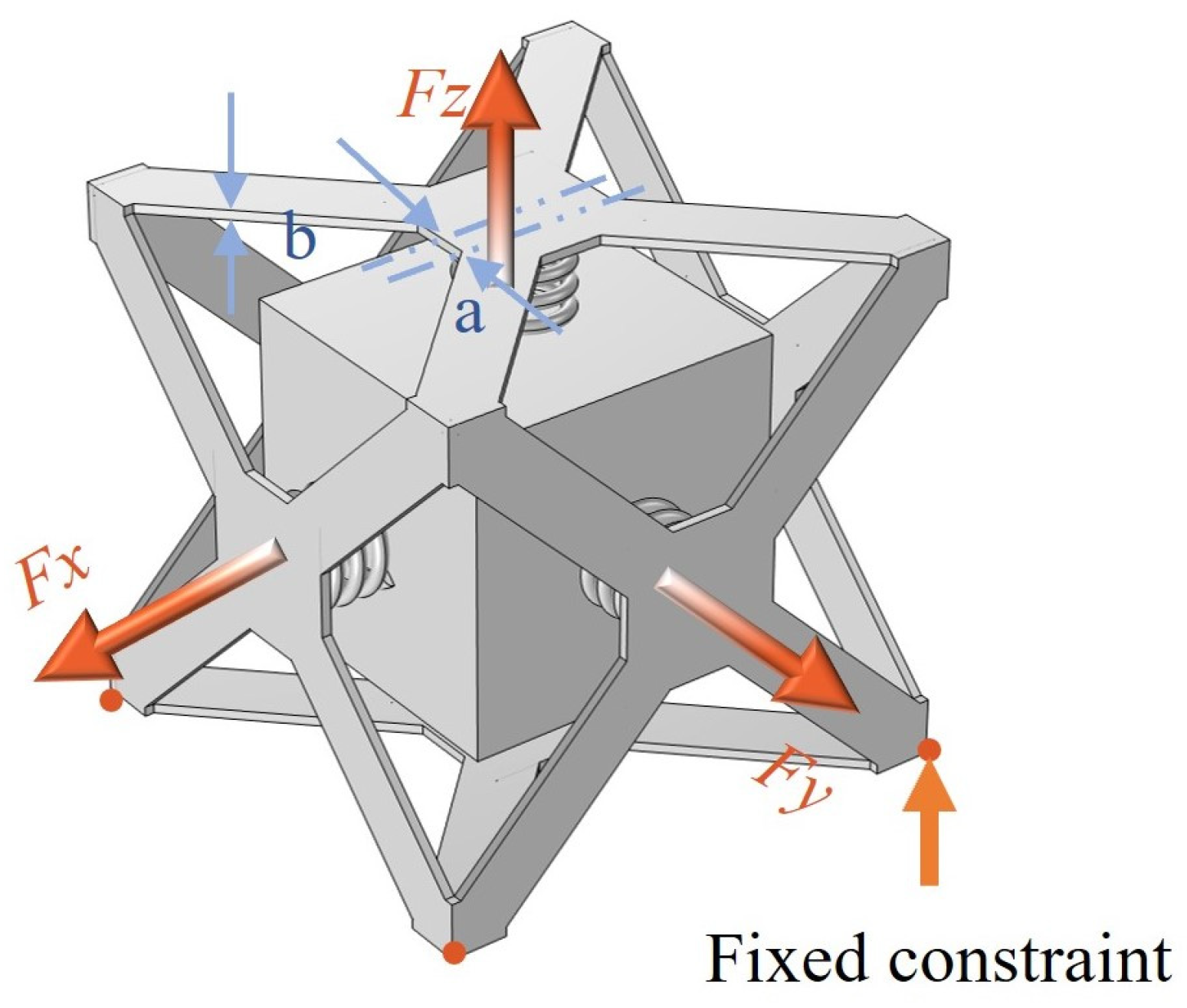
Based on the X-shaped configuration derived from topology optimization, this study focuses on two critical design parameters for systematic analysis: the distance a between the inner endpoint of the X-shaped strut and the plate centerline, and the plate thickness .
To approximate the overall loading conditions of the absorber, springs corresponding to the target frequency of the rigid shell are employed for the simulation. As illustrated in
Figure 5, a three-dimensional parametric geometric model of the DVA is established. In accordance with actual engineering installation conditions, fixed constraints are applied to the four corners of the bottom surface of the DVA. Subsequently, equal-amplitude excitation forces are then applied to the mass block in the X, Y, and Z directions, forming three loading cases. The displacement response amplitude of the mass block is calculated for each case. From these displacements, the stiffness of the absorber in the three directions is evaluated.
The mathematical model for parameter optimization is formulated as
where
denotes the total volume of the shell structure.
and
respectively represent the maximum and minimum values of the displacement response amplitude in the direction of the excitation force under the three working conditions.
is the average of these three displacement amplitudes.
is the constraint intensity coefficient, where a smaller value indicates a higher degree of isotropy. The constraint intensity is defined as the ratio of the difference between the maximum and minimum displacements to the average displacement.
denotes the global stiffness matrix dependent on design variables
a and
,
and
represent the global nodal displacement vector and load vector, respectively. This equality constraint ensures that the static equilibrium condition is satisfied throughout the optimization process. Additionally,
implies zero displacement, representing fixed constraints.
It should be noted that perfect isotropy is not attainable in this bottom-fixed absorber configuration due to the inherent asymmetry of the boundary conditions. The constraint intensity coefficient quantifies the acceptable deviation from perfect isotropy. A smaller value of enforces a tighter isotropy requirement at the cost of reduced lightweighting potential, representing a design trade-off that can be adjusted according to specific engineering needs.
Additionally, it is worth noting that within the linear elastic range, the displacement
u is linearly related to the applied force
through the stiffness
. When equal-amplitude excitation forces are applied in the three orthogonal directions, the maximum, minimum, and average displacements can be expressed as
where
,
, and
denote the structural stiffnesses in the
,
, and
directions, respectively.
and
represent the minimum and maximum values among
,
, and
.
Substituting these expressions into the definition of constraint intensity
yields
As shown above, the force magnitude cancels out completely in the ratio. Therefore, depends solely on the stiffness variation among the three orthogonal directions and is entirely independent of the applied force magnitude. Consequently, the specific value of the excitation force does not affect the optimization results, and the boundary conditions employed in the parameter optimization adequately represent the isotropy requirement under real loading conditions.
To accelerate the convergence of the iterative parameter optimization process, a Kriging surrogate modeling strategy is employed in this study. Mathematically, the Kriging model formulates the unknown response
as a combination of a global polynomial regression trend and a localized stochastic deviation, which is strictly expressed as
where
denotes the input vector of design variables (parameters
a and
b in this study),
is a vector of basis functions, and
is the corresponding vector of regression coefficients. The term
represents a stationary Gaussian random process with zero mean and variance
, which is utilized to capture highly nonlinear local variations. The spatial correlation between any two sampled points,
and
, is governed by the correlation function, and their covariance can be expressed as
where
is the spatial correlation function. In this study, the classical Gaussian correlation function is adopted to accurately quantify the distance weights between samples, wherein the unknown hyper-parameters
are determined via the maximum likelihood estimation method.
Based on this rigorous theoretical framework, an initial sample set comprising the design variables (a and b) and their corresponding constraint intensity values is obtained via high-fidelity simulations. By training the model with these samples, a highly accurate and continuous nonlinear mapping between the geometric parameters and the constraint intensity is established in the design space. This surrogate model facilitates the rapid identification of global optimal parameters while significantly reducing computational costs.
3.3. Spring Design
The stiffness of a single shell panel is difficult to quantify analytically, owing to its geometric complexity and boundary constraints. This poses a major obstacle in determining the spring parameters. To address this, a spring–shell series stiffness system is introduced as a baseline model. Finite element simulation is used to calculate its overall equivalent stiffness. In this simulation model, the optimized configuration is adopted for the shell panel, while the spring parameters are consistent with those of the conventional rigid shell scheme. Subsequently, based on the theoretical series stiffness Equations (8) and (9), an inverse derivation is performed. This establishes Equations (25) and (26) for calculating the stiffness of a single shell panel.
where
and
denote the spring axial stiffness and shear stiffness of the conventional rigid shell design scheme, respectively.
Figure 6a illustrates the finite element simulation setup for the series stiffness system. In the model, fixed constraints are applied to the four bottom corners of the panel. Meanwhile, displacement loads are respectively applied to the spring in the Y and Z directions. By extracting the reaction force data at the fixed constraints, the equivalent shear stiffness and equivalent axial stiffness of the series stiffness system are calculated.
It is noteworthy that if the effective height
, Young’s modulus
, wire diameter
, and mean coil diameter
are kept constant, the ratio
α between the shear stiffness and axial stiffness of the spring remains nearly constant, even if the effective number of coils
n is varied. This characteristic significantly reduces the complexity of the parameter solution. Based on this ratio relationship, Equation (11) is further derived as Equation (27).
Since both
and
in Equation (27) are known quantities, there is only one variable
in this formula. Therefore, in the design phase, precise matching of the stiffness required for the target frequency can be achieved by simply adjusting the effective number of coils
n. Considering the boundary condition that requires the spring ends to be ground flat, the relationship between the effective number of coils
n and the design number of coils
is given by Equation (28).
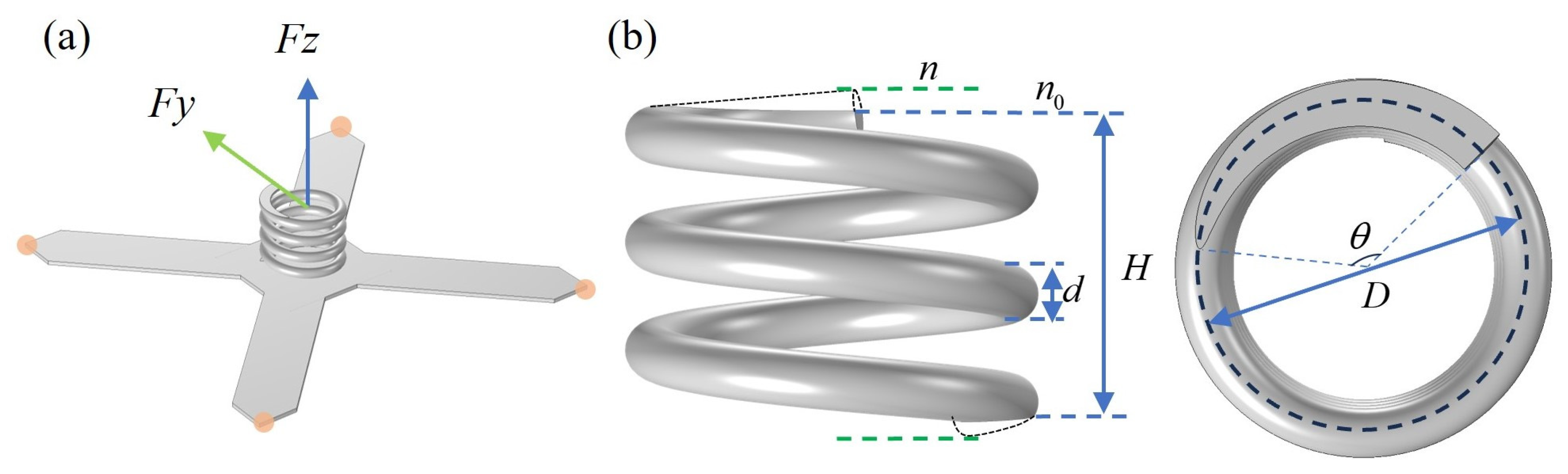
The spring design parameters are illustrated in
Figure 6b, where
represents the angle formed between the lines connecting the center to the start and end points of the ground flat end. Notably, since the total stiffness of a series system is always lower than that of any individual component, a physical feasibility domain exists for this design method. Specifically, the total stiffness required for the target absorber must be lower than the sum of four times the shear stiffness and two times the axial stiffness of the optimized shell. This is a necessary prerequisite to ensure that the spring stiffness has a positive real solution and the structure is physically achievable.
4. Optimization Design Case Study
4.1. Lightweight Design of the Shell
This study optimizes a vibration absorber with a target natural frequency of 50 Hz and a mass block of 4 kg. The single shell panel is defined as a square with a side length of 160 mm. The material properties of the aluminum shell are consistent with those described in
Section 2. Within this panel, a central square area with a side length of 50 mm is designated as the non-design domain. Based on the topology optimization results, the initial configuration is determined to be an X-shaped structure.
During the parameter optimization stage, considering geometric constraints, the range for parameter a is set to [1, 25] mm, and the range for parameter is set to [1, 5] mm. To achieve lightweight design while satisfying the design constraints, a grid discretization method is adopted to obtain initial sample data for the Kriging model. The step sizes for parameters a and are set to 1 mm and 0.5 mm, respectively. Consequently, a sample database containing 108 initial sample points, along with their constraint intensity and shell volume data, is constructed. This lays the foundation for the subsequent surrogate model training.
As illustrated in
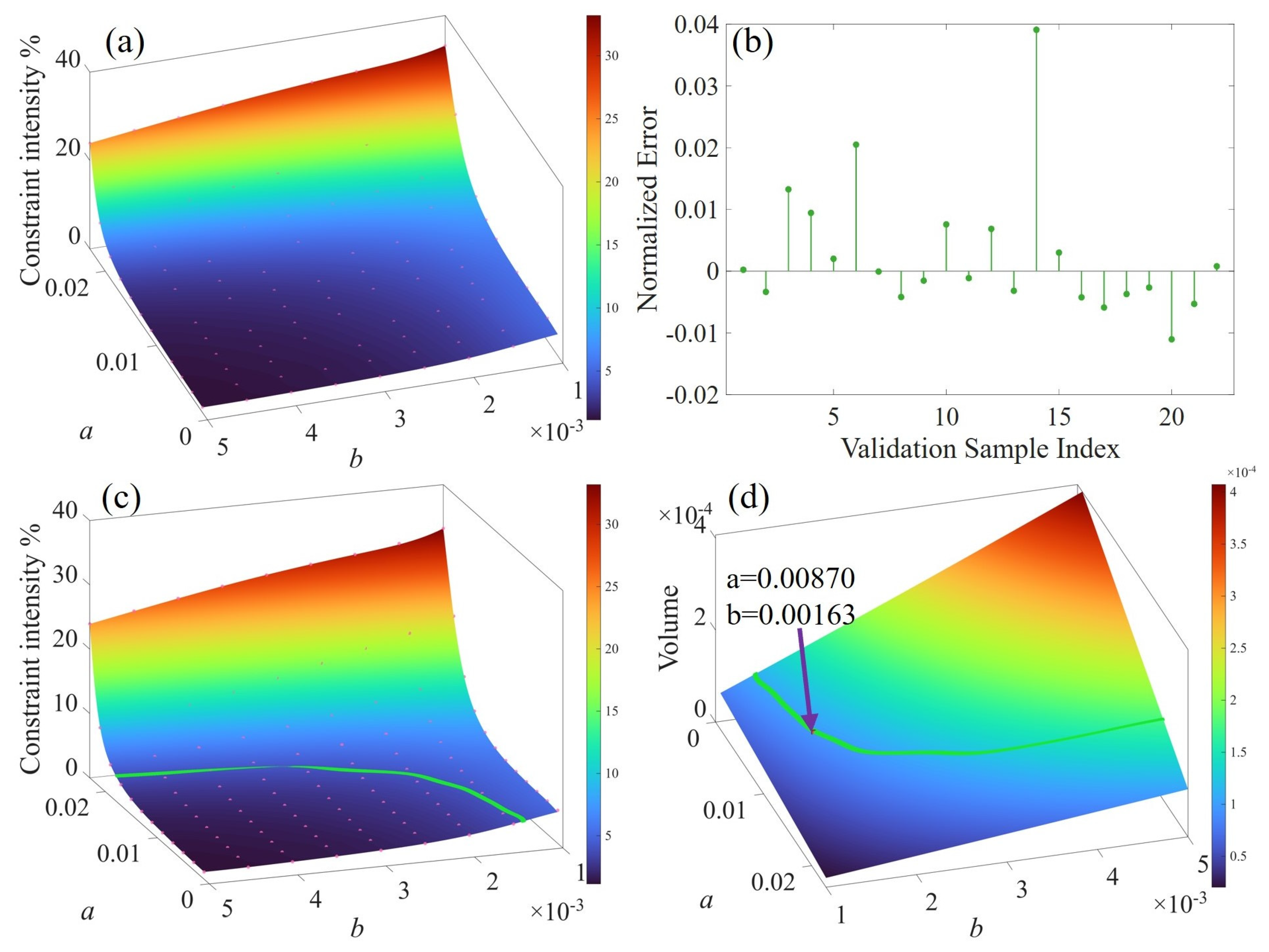
Figure 7a, the Kriging response surface is fitted using 80% of the sample data, marked as pink points, while the remaining 20% is used for cross-validation. The normalized error is defined as the ratio of the prediction deviation to the mean of the true sample values. As shown in
Figure 7b, the error analysis reveals that the maximum error is within 4%, and the error for 90% of the samples is below 2%. These results indicate that the constructed Kriging model can effectively replace physical simulations, satisfying the prediction accuracy requirements for structural optimization.
Given the reliability of the verification results, the complete sample database is used to construct the final Kriging surrogate model. To determine the minimum shell mass that satisfies the constraint intensity, the parameters
a and
are discretized with high density within the design space (1000 divisions per axis). Then, the model is used to calculate the corresponding constraint intensity.
Figure 7c displays the response surface of the constraint intensity fitted using the complete sample set. Based on the constraint intensity coefficient
set in this study, the green markers in the figure visually define the feasible design domain. This domain corresponds to a constraint intensity range of 3.96% to 4.04%.
The constraint intensity
is defined in Equation (22). By transforming the equation, we obtain
Based on
and
,
Thus, is used to constrain the dispersion between the natural frequencies in three directions. Generally, is a small positive value, which is set to 0.04 in this study.
The shell volume is uniquely determined by the geometric parameters
a and
.
Figure 7d displays the response surface of the volume fraction, fitted using approximately
discrete sampling points. The red marker in the figure indicates the global minimum volume solution that satisfies the isotropic constraints. For this optimized shell configuration, the corresponding geometric parameters are
and
.
4.2. Static Analysis
Based on the determined optimal parameters
a and
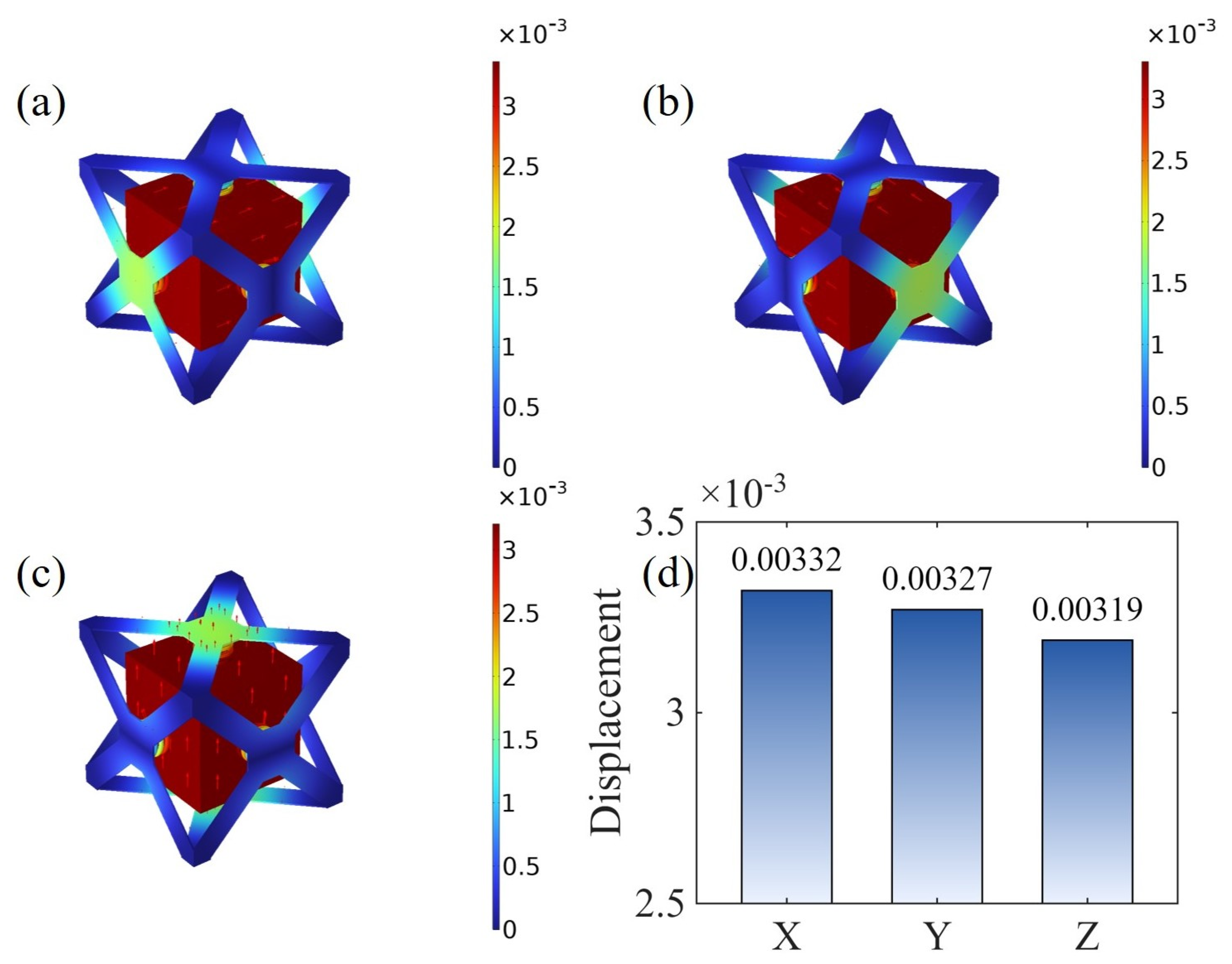
, the geometric configuration of the absorber shell is reconstructed. To verify its mechanical performance, the same boundary constraints and loading conditions as in the parameter optimization stage are applied. The resulting displacement fields under these conditions are illustrated in
Figure 8a–c. Subsequently, the displacement components in the X, Y, and Z directions corresponding to the loading surfaces are extracted, as shown in
Figure 8d. Based on the data in
Figure 8d, the actual constraint intensity is calculated to be 4.0%. This result not only verifies the prediction accuracy of the surrogate model but also ensures that the optimized absorber possesses excellent isotropic mechanical characteristics.
4.3. Determination of Spring Parameters
Based on the optimized geometric parameters a and , the equivalent axial and shear stiffnesses of the series stiffness system are obtained via finite element simulation. This system is composed of the spring from the conventional rigid shell scheme and the optimized shell. Subsequently, using Equations (25) and (26), the axial and shear stiffnesses of the single optimized shell panel are calculated to be approximately N/m and N/m, respectively.
Adopting the spring material and geometric parameters defined in
Section 2. Based on these values, the coefficient
α in Equation (27) is calculated to be 1.65. Consequently, the target shear stiffness of the spring is inversely determined to be approximately
N/m using this equation.
Through a parametric sweep of the effective number of coils, the mapping relationship between the coil number and shear stiffness is established. Matching the target stiffness yields an effective number of coils . In this design, the parameter corresponds to 1.5. Thus, the design number of coils is set to 2.7.
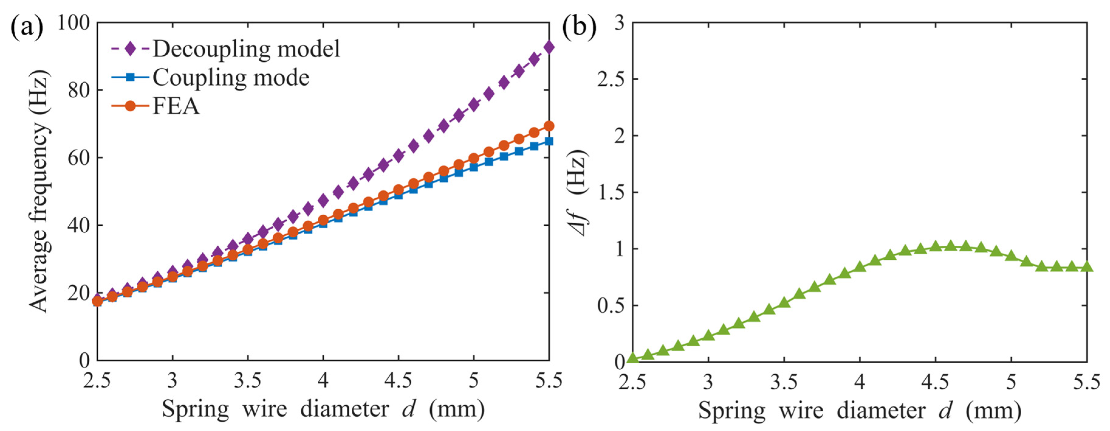
To further verify the general applicability of the optimized shell structure and investigate the influence of spring parameters on the dynamic characteristics of the DVA, a parametric analysis is conducted on the spring wire diameter . In this analysis, the effective height and the design number of coils are kept constant at 26 mm and 2.7, respectively. Meanwhile, the wire diameter is varied from 2.5 mm to 5.5 mm. The natural frequencies of the absorber are calculated using two distinct methods. The first approach is a decoupling model relying on a rigid-body assumption for the shell. The second approach is a coupling model accounting for the combined stiffness of the spring and the shell. These analytical results are subsequently compared with the average natural frequencies of the translational modes obtained via finite element analysis.
As illustrated in
Figure 9a, tuning the spring wire diameter enables the absorber to cover a broad natural frequency range from 18 Hz to 70 Hz. Notably, as the wire diameter increases, the deviation between the decoupling model and the simulated true values grows sharply. This leads to severe overestimation of the system’s natural frequencies. This discrepancy arises because the elastic deformation of the shell itself becomes non-negligible when coupled with high-stiffness springs. Such deformation invalidates the rigid-body assumption inherent in the decoupling model. In contrast, the proposed coupling model maintains high consistency with the finite element analysis results across the entire parameter sweep. This demonstrates the superior accuracy and necessity of the coupling model for designing lightweight absorbers with precise natural frequencies.
Furthermore, evaluating the isotropic characteristics of the optimized structure across different target frequencies is crucial. In this study, structural isotropy is formally evaluated based on modal stiffness equivalence. According to the fundamental dynamic formula , the natural frequency is determined by the square root of the ratio of stiffness to mass. For the cubic absorber configuration, the mass of the block is identical in the three orthogonal directions, such that the natural frequency in each direction depends solely on its corresponding modal stiffness. Therefore, a tight clustering of the three translational frequencies mathematically guarantees modal stiffness equivalence.
To quantify this property, the difference between the maximum and minimum natural frequencies among the first three translational modes is defined as
. This specific metric is extracted from the finite element analysis and plotted in
Figure 9b. The results indicate that although the spring stiffness changes significantly with the wire diameter, the metric
consistently remains at a low level. The global maximum of this frequency difference does not exceed 1.1 Hz. This observation confirms that the excellent isotropic performance of the optimized shell is not compromised by variations in the spring parameters.
In addition to geometric parameters, the elastic modulus of the spring material directly governs the spring stiffness. If the elastic modulus of the spring after manufacturing deviates from the nominal design value, the actual natural frequency of the absorber will shift accordingly.
4.4. Modal Analysis and Shell Mass Assessment
The final isotropic DVA is assembled from 6 optimized shell panels, 6 stiffness-matched springs, and a 4 kg mass block.
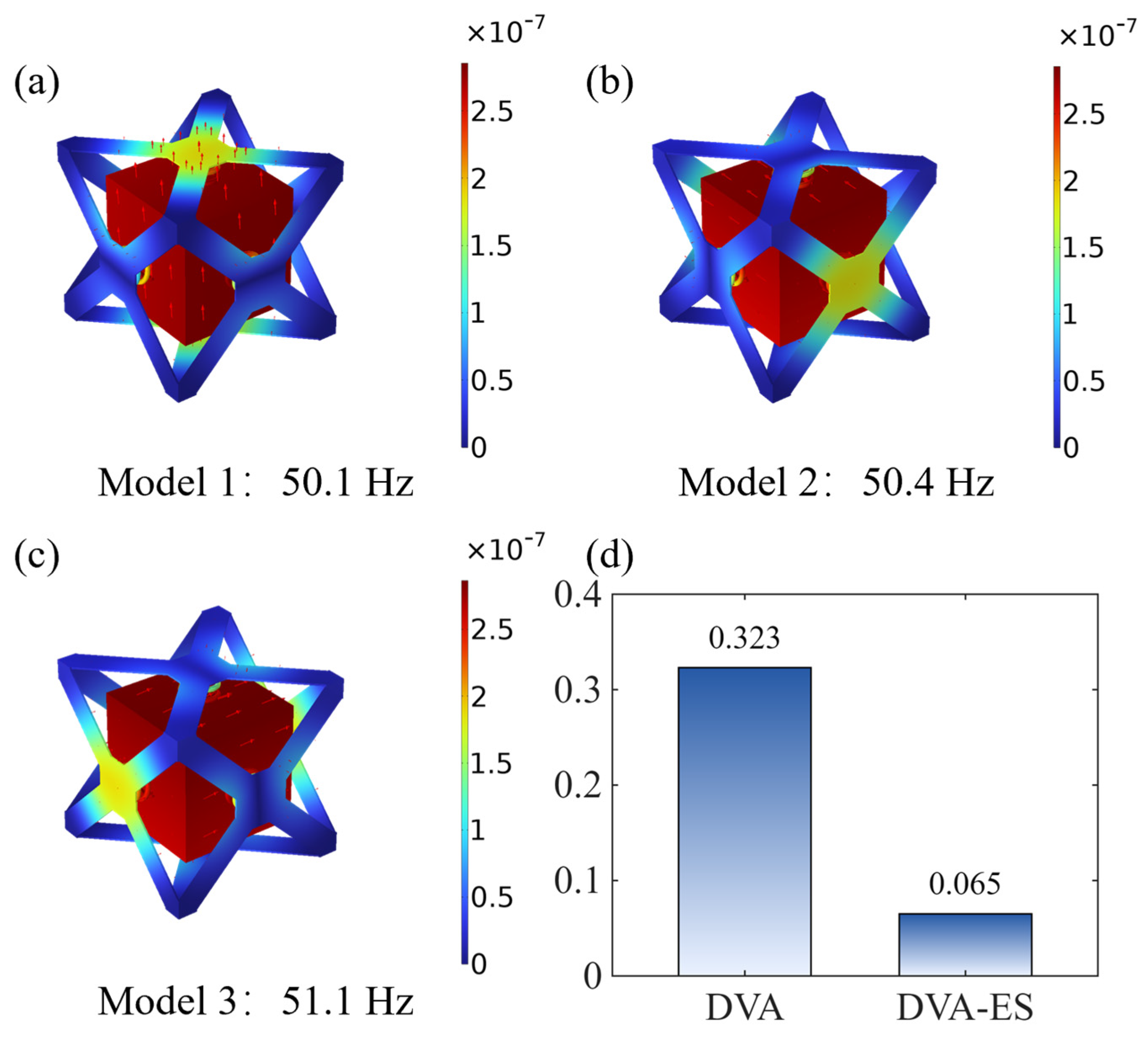
Figure 10a–c display the first three translational mode shapes obtained via finite element simulation. The corresponding natural frequencies match the 50 Hz design target with a relative error of less than 3%. Furthermore, the frequency spread of the three translational modes is 1 Hz. This high degree of spectral concentration validates the effectiveness of the lightweight design method for isotropic DVA proposed in this paper.
Beyond frequency characteristics,
Figure 10d further highlights the lightweight advantages of the optimized elastic shell configuration. The mass of the conventional rigid shell reaches 1.29 kg, accounting for 32.3% of the mass block. In contrast, the mass of the optimized elastic shell in this study is approximately 0.26 kg. This represents a mass reduction of 79.8%. Consequently, the mass ratio drops to 6.5%, which corresponds to a decrease of 25.8% compared to the rigid shell scheme. These results fully demonstrate that the proposed design method achieves significant lightweighting while ensuring isotropic dynamic performance. Therefore, the method holds great value for reducing manufacturing costs and enhancing engineering practicality.
4.5. Vibration Suppression Effectiveness in a Beam Model
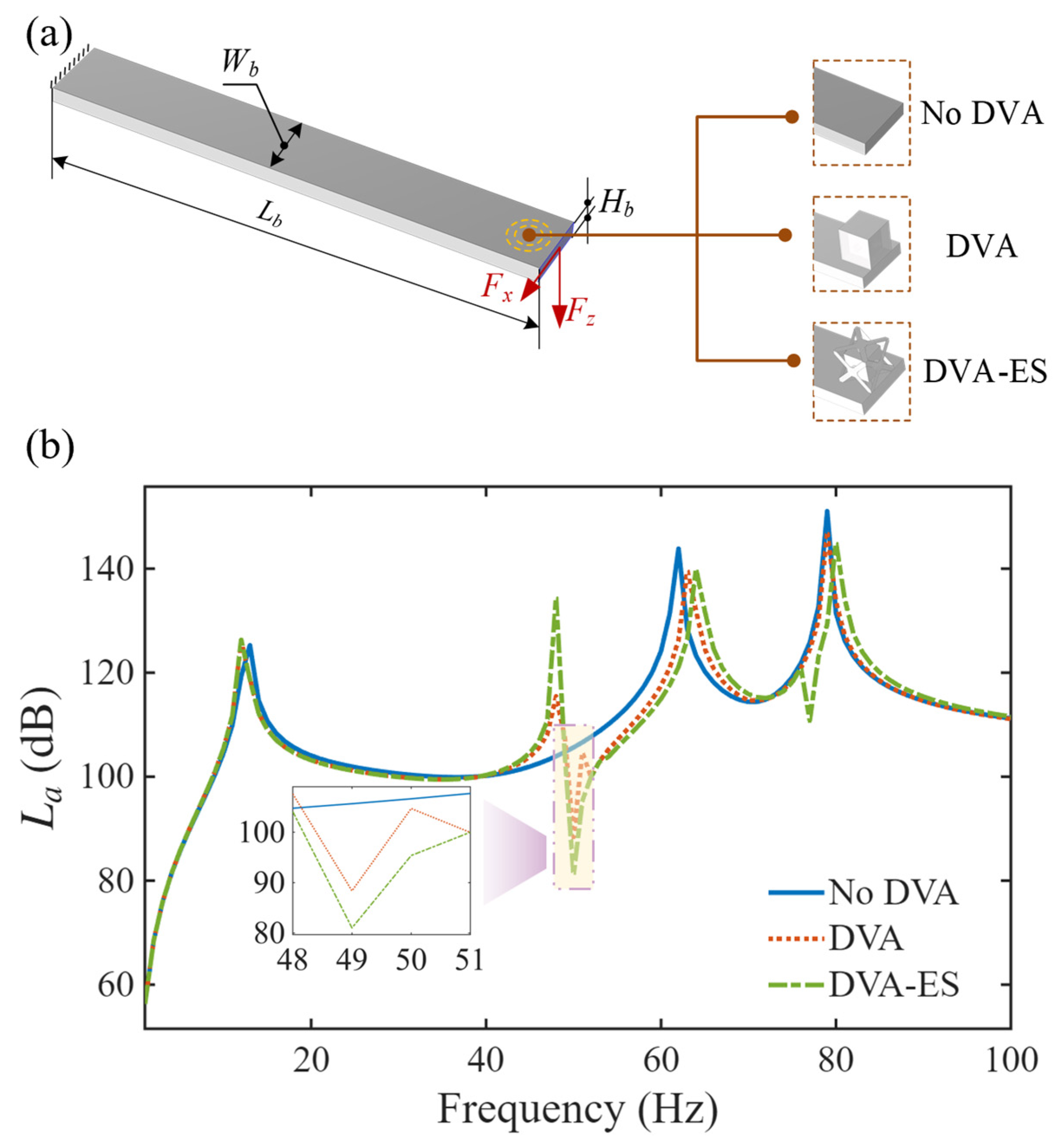
To assess the effectiveness of the optimized design in structural vibration suppression, a beam model is established, as illustrated in
Figure 11a. Its dimensional parameters are
and
. The material properties of the beam are set as follows: Young’s modulus
, Poisson’s ratio
, and density
. The total mass of the beam is 282.6 kg. A fixed constraint is applied to one end of the beam, while the other end is subjected to excitation forces in the X and Z directions with an amplitude of 10 N. The conventional rigid shell DVA and the DVA with optimized elastic shell are separately installed at the free end of the beam.
To ensure a fair comparison, the total mass of the two DVAs is kept constant. This constraint also reflects engineering practice, where the total added mass of a vibration absorber is often strictly limited. The shell is structurally necessary but contributes nothing to vibration suppression. For the DVA with optimized elastic shell, the shell mass is approximately 0.26 kg and the mass block is 4 kg. In contrast, the conventional DVA features a shell mass of approximately 1.29 kg and a mass block of 2.97 kg. Regarding its springs, the effective number of coils is adjusted to 2.5 and the wire diameter is set to 4 mm to match the target frequency, while the remaining parameters are consistent with the baseline design defined in
Section 2. The first three translational modal frequencies of this configuration are 49.8 Hz, 50.4 Hz, and 51.0 Hz, confirming that the absorber remains tuned to the 50 Hz target. Consistent with the theoretical assumption established earlier, metal springs inherently possess extremely low damping. Therefore, the damping ratio was set to zero in this finite element simulation.
In this study, the loading surface is defined as the assessment region to quantitatively evaluate the structural vibration level. The surface-averaged root mean square (RMS) acceleration is computed for this area and utilized as the critical metric for measuring vibration amplitude. The corresponding formula is expressed as
where
represents the area of the loading surface, while
,
, and
denote the acceleration magnitudes of the local region in the X, Y, and Z directions, respectively.
To quantitatively evaluate the vibration amplitude in terms of decibels, the surface-averaged RMS acceleration (
) is converted into the acceleration level (
). The corresponding formula is expressed as
where
is the reference acceleration.
The frequency response curves for three cases are presented in
Figure 11b: the primary system without a DVA (labeled as ‘No DVA’), the system with the conventional rigid shell DVA (labeled as ‘DVA’), and the system incorporating the DVA with optimized elastic shell (labeled as ‘DVA-ES’). For the ‘No DVA’ case, the acceleration level of the loading surface at the target frequency of 50 Hz is 105.6 dB. After installing the conventional rigid shell DVA (‘DVA’), a certain suppression effect is observed at 50 Hz, where the response decreases to 88.4 dB, corresponding to a reduction of 17.2 dB. Significantly, the DVA with optimized elastic shell (‘DVA-ES’) further reduces the acceleration level to 81.0 dB, achieving an additional attenuation of 7.4 dB compared to the rigid shell scheme. These results indicate that, under the condition of constant total mass, increasing the mass of the mass block significantly enhances the vibration reduction performance. This validates the effectiveness and engineering significance of the optimized design.
Table 1 and
Table 2 summarize the performance differences between the two designs.
Table 1 compares the absorbers at an equal mass block of 4 kg. Max. deviation denotes the maximum percentage deviation of an individual natural frequency from the 50 Hz design target.
Table 2 compares the absorbers at an equal total mass of 4.26 kg. As described in the beam model, the rigid-shell DVA must use a 2.97 kg mass block to satisfy this constraint. The DVA-ES accommodates the full 4 kg block.
5. Experimental Verification of Isotropic Properties
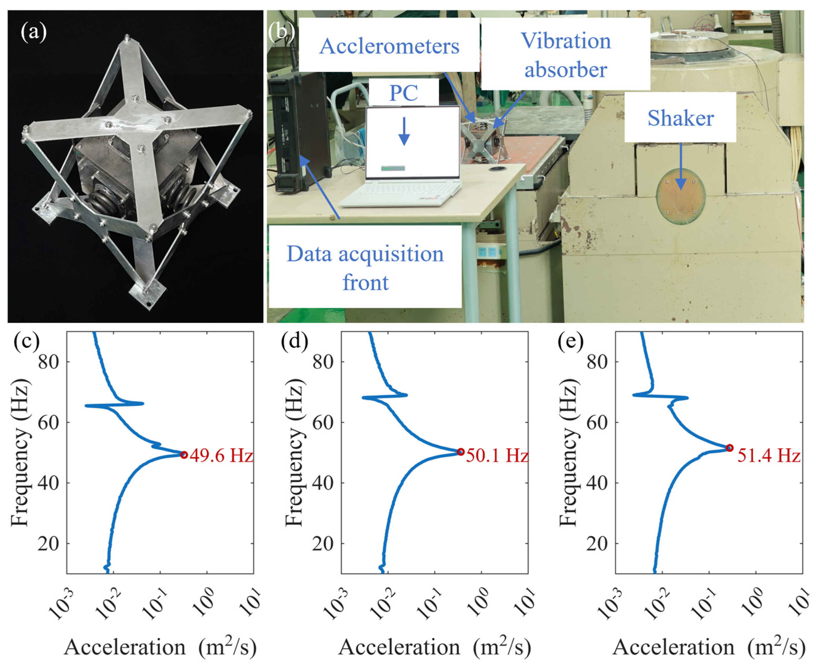
A DVA prototype was designed and manufactured specifically to verify the isotropic properties of the optimized structure. In consideration of practical assembly requirements, additional assembly features were incorporated into the shell structure during fabrication. These features include screws and fasteners, an extra base plate for bottom fixation, connectors between the springs and the shell panels, and geometric allowances at the shell-to-shell joints. The final fabricated prototype is presented in
Figure 12a, which has a measured shell mass of 0.32 kg.
As illustrated in
Figure 12b, a vibration test bench was set up for the systematic verification of the elastic shell DVA’s dynamic characteristics. During the test, sine sweep acceleration excitation of 0.1 g was applied individually along the three orthogonal directions (X, Y, and Z). The sweep range was configured from 5 to 100 Hz.
The collected signals were processed via denoising and Fast Fourier Transform (FFT) to obtain the logarithmic spectrum characteristics within the 10–90 Hz frequency band, as presented in
Figure 12c–e. In the figure, red markers denote the positions of the resonance peaks. The measured results reveal that the first three natural frequencies of the DVA are 49.6 Hz, 50.1 Hz, and 51.4 Hz, respectively. The maximum relative error between the measured natural frequencies and the 50 Hz design target is 2.8%. Analysis of the experimental data indicates that the difference between the maximum and minimum natural frequencies of the three translational modes is 1.8 Hz.
The finite element simulation gives a frequency spread of 1.0 Hz among the first three translational modes. The experimental measurement yields 1.8 Hz, an increase of only 0.8 Hz. This small difference confirms that the absorber retains excellent isotropic behavior. The discrepancy between simulation and experiment may be attributed to manufacturing tolerances and non-ideal assembly. Manufacturing introduces geometric and material uncertainties. The shell panels carry machining tolerances, and material properties can vary across production batches. In addition, the simulation assumes perfectly rigid connections among all components, whereas the physical prototype is joined with screws. These mechanical joints introduce local compliance that the finite element model does not capture. This additional compliance may amplify the stiffness differences among the three directions. Nevertheless, the measured frequency spread remains small. This confirms that the proposed design method is robust to the imperfections in the practical manufacturing and assembly.
6. Conclusions
This study proposes a collaborative design method based on an elastic shell architecture. It addresses the contradiction between multi-directional vibration suppression and lightweighting of DVAs. Two key components are established: an isotropic dynamic model of coupling spring and shell stiffnesses, and a collaborative design framework integrating topology and parameter optimization. Together, they realize the lightweight design of isotropic absorbers. The X-shaped elastic shell obtained through topology optimization effectively overcomes the anisotropy caused by insufficient shear stiffness. The experimental measurements show a frequency spread of only 1.8 Hz among the three translational modes. This result validates both the stiffness coupling model and the collaborative design framework. Compared with the conventional rigid shell scheme, this configuration achieves a mass reduction of 79.8% while satisfying mechanical performance requirements. Benefiting from the increased ratio of effective vibration mass, the optimized absorber exhibits stronger suppression capability under the constraint of equal total mass. The simulation results indicate that its vibration response is further reduced by 7.4 dB compared to the rigid shell scheme.
Furthermore, this proposed method exhibits excellent engineering applicability. The optimized structure is relatively simple and can be easily produced using traditional machining methods rather than expensive 3D printing techniques. This ensures low manufacturing complexity and significantly reduces production costs. Additionally, the design framework is highly scalable. Although demonstrated through a specific case study with a 4 kg mass and a 50 Hz target frequency, this methodology is not restricted to these parameters. It can be readily applied to design isotropic absorbers with varying mass configurations and different target frequencies to meet diverse industrial demands.
The proposed design method provides new theoretical support and engineering solutions for addressing the challenges of lightweight design in complex multi-directional vibration control. It should be noted that the present study assumes rigid mounting conditions, under which the proposed method has been validated. Future work will extend this framework in two directions: accounting for flexible mounting conditions to broaden engineering applicability, and integrating damping materials and variable-stiffness absorber analysis for enhanced dynamic performance.