Article

Variable-Step Semi-Implicit Solver with Adjustable Symmetry and Its Application for Chaos-Based Communication

1
Youth Research Institute, Saint Petersburg Electrotechnical University “LETI”, 197022 Saint Petersburg, Russia
2
Computer-Aided Design Department, Saint Petersburg Electrotechnical University “LETI”, 197022 Saint Petersburg, Russia
*
Authors to whom correspondence should be addressed.
Mathematics 2025, 13(8), 1229; https://doi.org/10.3390/math13081229
Submission received: 10 March 2025 / Revised: 2 April 2025 / Accepted: 6 April 2025 / Published: 9 April 2025

Abstract

:
In this article, we introduce a novel approach to numerical integration based on a modified composite diagonal (CD) method, which is a variation of the semi-implicit Euler–Cromer method. This approach enables the finite-difference scheme to maintain the dynamic regime of the solution while adjusting the integration time step. This makes it possible to implement variable-step integration. We present a variable-step MCD (VS-MCD) version with a simple and stable Hairer step size controller. We show that the VS-MCD method is capable of changing the dynamics of the solution by changing the symmetry coefficient (reflecting the ratio between two internal steps within the composition step), which is useful for tuning the dynamics of the obtained discrete model, with no influence of the appropriate step size. We illustrate the practical application of the developed method by constructing a direct chaotic communication system based on the Sprott Case S chaotic oscillator, demonstrating high values in the largest Lyapunov exponent (LLE). The tolerance parameter of the step size controller is used as the modulation parameter to insert a message into the chaotic time series. Through numerical experiments, we show that the proposed modulation scheme has competitive robustness to noise and return map attacks in comparison with those of modulation methods based on fixed-step solvers. It can also be combined with them to achieve an extended key space.

1. Introduction

In the history of ordinary differential equation (ODE) solvers, computationally efficient explicit algorithms with enhanced stability and accuracy and the ability to preserve geometric structures, such as the energy or symplectic properties, when simulating conservative dynamical systems were first combined into semi-implicit algorithms like the Euler–Cromer and Störmer–Verlet algorithms, which were originally applied to Hamiltonian systems [1,2,3]. The development of semi-implicit and diagonal implicit methods aimed to generalize these techniques for all classes of differential equations [4,5,6]. However, these methods did not meet the conditions of symmetry, making them unsuitable for application in composition schemes. Further research led to the development of symplectic partitioned Runge–Kutta methods [7] and implicit–-explicit Runge–-Kutta methods [8]. There have also been efforts to develop methods that combine explicit and implicit approaches [9,10,11].
Recently, diagonally implicit numerical integration methods, abbreviated as D-methods, were introduced and explored [12,13]. These methods could be applied to dissipative ODEs and bridge the gap between the simplicity of explicit schemes and the robustness of fully implicit approaches. A defining feature of D-methods is their diagonal implicitness, which refers to the structure of their system equations. Unlike fully implicit methods that require nonlinear systems to be solved in their full matrix form, D-methods allow for the decoupling of equations into a diagonal form. Thus, they may be efficiently resolved using line-by-line straightforward iterative techniques, such as the simple iteration method outlined in [12,14], line by line. Consequently, they are computationally lightweight while retaining stability for stiff systems, making them viable for complex dynamical problems beyond Hamiltonian mechanics, including non-conservative and dissipative systems.
A special form of D-method, the composition D-method (CD) or the self-adjoint semi-implicit method, has demonstrated a particular perspective in the simulation of chaotic systems. The self-adjoint property of the CD method ensures time reversibility and symmetry, critical for maintaining the accuracy of long-term simulations [12,15,16]. Unlike some numerical schemes that artificially dampen chaos or induce periodicity, the CD method preserves the inherent chaotic behavior of both conservative and dissipative systems [17]. This robustness prevents trajectories from deviating into non-chaotic orbits (a common issue in discrete approximations), making it invaluable for studying phenomena like turbulence, celestial mechanics, or chaotic oscillators. As highlighted in [17], the CD method’s ability to retain chaotic dynamics without suppression underscores its superiority in applications requiring accurate long-term stability and the structural integrity of solutions. All of these aforementioned points make it attractive to apply CD methods in various practical systems based on chaos.
Applications of chaos are presented in many different fields, such as sensors with enhanced sensitivity [18,19,20], pseudo-random number generators [21], image encryption algorithms [22], signal denoising [23,24], and chaos-based communication systems (CCSs) [25,26,27], which include a number of approaches. One particular approach is to embed a binary message into the chaotic carrier, which is called a direct CCS (DCCS). Restoring a message from a chaotic carrier can be performed using cross-correlation (as well as other numerical operations) or through the synchronization of the chaotic oscillator on the receiver side with the chaotic waveform obtained from a communication channel. Such types of DCCSs are called non-coherent and coherent, respectively. A coherent CCS allows for more precise manipulation of the chaotic carrier, resulting in more secure communication, with a lower possibility of a third party detecting and reading the message [26]. Coherent DCCSs use such types of modulation as chaos-based CDMA, chaotic symbolic dynamics, modulation based on multistability [28,29], and chaotic shift keying (CSK), which is subdivided into several approaches, including frequency-modulated CSK [30], quadrature CSK [31,32,33], parameter modulation (PM), and symmetry coefficient modulation (SCM) [34]. The last method uses a CD solver with variable symmetry and demonstrates a flexible trade-off between the noise resistance, security, and possible transfer rates.
Our new finding is that the variable-step modified CD (VS-MCD) method allows for the creation of finite-difference schemes of chaotic oscillators that accurately synchronize with each other [35] only when the parameters of the step controller match, even if the parameters of the continuous models of synchronized oscillators are identical. This finding allows the variable-step settings in the solver to be used as the modulation parameters for chaotic communication systems, providing yet another element of the secure key space. The main advantage of the new method, however, is its high robustness to additive noise based on the fact that the variable-step modulation forms a phase-like modulation.
Given the above, the novelty and contributions of this study are as follows:
  • We propose a new formulation of the symmetry parameter for the CD method, which is expressed in such a way that does not depend on a particular value of the integration step. This expression makes it straightforward to combine the CD method with any variable-step controller, e.g., that presented in [36]. We investigate the proposed method using two chaotic systems and show that the chaotic regimes depend mainly on the symmetry coefficient but not on the step size, except at large step size values at the edge of stability.
  • We propose a novel symmetry coefficient modulation approach to chaotic communication by implementing modulation through a variable-step-size controller parameter, namely tolerance (tol). We illustrate the developed approach with the CSS based on the Sprott Case S chaotic oscillator.
  • We analyze the parameters of the developed communication system by using a quantified return map analysis (QRMA) to measure the confidentiality and bit error rate (BER) to measure noise immunity. A comparative analysis is presented which shows that the modulation technique developed has a higher performance compared to that of alternative modulation approaches in both systems estimated at lower signal-to-noise ratio (SNR) levels.
Schematically, the renewed family of CSK methods is presented in Figure 1 as a Euler diagram. Each circle represents an independent type of modulation: through a parameter of the continuous system; through a symmetry coefficient (for methods from the CD family) or another adjustable parameter of the numerical methods (for the Runge–Kutta method and other methods); or through tolerance or another parameter of the variable-step controller. The intersections of the circles show that these methods can be applied in combination with each other. Particularly, all three modulation methods can be combined, and each of them (except symmetry) can involve two or more variable parameters, forming a key space of high dimensionality.
The rest of this paper is organized as follows. In Section 2, we present a composite diagonal method with fixed and variable steps, as well as equations for the chaotic oscillators under study and the scheme of the chaotic communication system. In Section 3, we present the results of our numerical study, including the metrics for CCS estimation. Section 4 discusses the results presented and concludes this paper.

2. Materials and Methods

2.1. Composite Diagonal Methods with a Fixed Integration Step

Let us consider a CD method Ψ [12] with the integration step size h:
Ψ h = Φ h 2 * Φ h 2 .
It is a composition of a pair of basic adjoint D-methods Φ h 2 and Φ h 2 * taken with a halved step size h 2 . Consider the application of the CD method to the following third-order autonomous initial value problem:
x ˙ y ˙ z ˙ = f ( x , y , z ) ,
where f = ( f 1 , f 2 , f 3 ) .
In the proposed entry, Φ h 2 is the Euler–Cromer method, which has the following finite-difference scheme:
x n + 1 2 = x n + h 2 f 1 ( x n , y n , z n ) , y n + 1 2 = y n + h 2 f 2 ( x n + 1 2 , y n , z n ) , z n + 1 2 = z n + h 2 f 3 ( x n + 1 2 , y n + 1 2 , y n ) .
In another case, Φ h 2 * is a diagonal-implicit D-method written in the reverse order:
z n + 1 = z n + 1 2 + h 2 f 3 ( x n + 1 2 , y n + 1 2 , z n + 1 ) , y n + 1 = y n + 1 2 + h 2 f 2 ( x n + 1 2 , y n + 1 , z n + 1 ) , x n + 1 = x n + 1 2 + h 2 f 1 ( x n + 1 , y n + 1 , z n + 1 ) .
However, as was shown in our works, dividing the step in half is only a special case from the general family of CD methods. Scheme (1) may be modified by introducing the symmetry coefficient s, applied to the step size h, which is now split into two non-equal parts:
h 1 = ( 1 s ) h , h 2 = s h .
Then, the CD method with the integration steps h 1 and h 2 can be written as follows:
Ψ h = Φ h 2 * Φ h 1 .
In the literature, the value s is called the symmetry coefficient [38].
A notable limitation of CD methods is their dimensionality constraint: they are defined for systems of a dimension N 2 . For first-order systems ( N = 1 ), the scheme collapses into explicit and implicit Euler methods, losing its distinctive advantages. This restriction arises because the diagonal structure of the method relies on coupling between multiple system variables, which is absent in one-dimensional systems. However, in practice, one-dimensional systems are rare, and this drawback is not significant.

2.2. A Novel Expression of the Symmetry Coefficient

In the classical CD method, the symmetry parameter s directly affects the step size, essentially its scaling factor. This makes it difficult to use with variable-step controllers. To solve this issue, a new symmetry scaling factor s is introduced, further called the symmetry distortion coefficient, which affects the step size additively rather than multiplicatively. Let us begin with the following considerations:
s = ( s 1 2 ) h .
With this new notation, the integration steps h 1 and h 2 are calculated as follows:
h 1 = h ( 1 s ) = h ( 1 s h 1 2 ) = 1 2 h s , h 2 = h s = h ( s h + 1 2 ) = 1 2 h + s .
An important point is the range of changes in the parameters considered. The size of the integration step is determined during the modeling process, depending on the complexity of the problem. In terms of geometry, the old symmetry coefficient s should range from 0 to 1 [38]. However, in another study, it was found that the symmetry coefficient could go beyond this range [34]. This approach resembles compositional schemes. As for the new symmetry coefficient s , we recommend that it be slightly smaller than the integration step size for practical use. This coefficient can be considered a small disturbance.
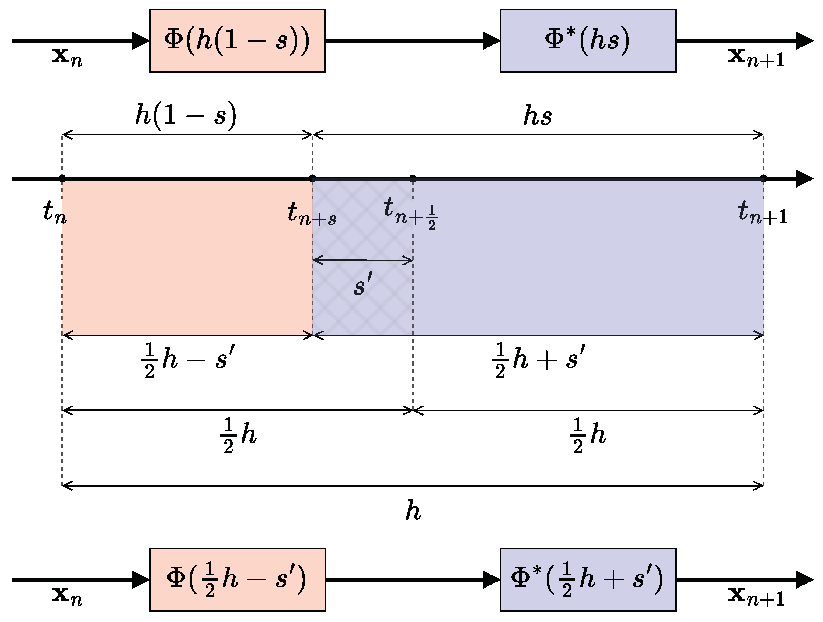
Figure 2 shows a graphical representation of the old and new symmetry coefficients. In the upper part of the figure, there is an integration step with variable symmetry which affects the step size multiplicatively [38]. At the bottom of the figure, there is an integration step with novel variable symmetry which affects the step size additively. The central part of the figure shows that these methods may be equivalent in cases of numerical integration over time. When using this formula to calculate the step values h i , the resulting mathematical models of chaotic signal generators are completely equivalent; however, the exact value of the symmetry distortion coefficient s remains constant for different values of the integration step.
Now, having received a new parameter for the integration method which does not depend on the integration step, we can synthesize extrapolation schemes that preserve the discrete modes obtained by changing the coefficient s . Using these extrapolation schemes, we can implement controlled-step solvers, which are described in more detail in the next subsection.

2.3. CD Methods with Variable Integration Steps

Let us explain a technique for increasing the order of the numeral integration method using extrapolation schemes [36]. Take some sequence m 1 < m 2 < < m k with a length equal to k; for each element in the sequence, we obtain the step sizes h j = h m j . The solutions obtained with the steps h j where T j , 1 = Ψ h m j Ψ h m j Ψ h m j give the first column of the extrapolation table:
T 1 , 1 T 2 , 1 T 2 , 2 T 3 , 1 T 3 , 2 T 3 , 3 T k , 1 T k , 2 T k , k 1 T k , k .
The terms in the table which are located to the right of T j , 1 are calculated consistently, moving through the columns using the following expression:
T j , i + 1 = T j , i + T j , i T j 1 , i ( m j m j i ) p 1 ,
where p = 2 for the symmetric method, and p = 1 in the opposite case. As a result, T k , k contains a high-order approximation.
Let us describe the variable-time-step approach based on extrapolation solvers. At the beginning, we obtain the error between the high-order approximation and the estimation approximation.
e r r n = T k , k 1 T k , k .
Next, to compute the new step size, we use a standard Hairer regulator for extrapolation methods without step rejection [36]:
h n + 1 = 0.94 h n ( 0.65 t o l e r r n ) 1 2 k 1 ,
where t o l is the desired tolerance value used as the modulation parameter;
e r r n is the error (9) at the current integration step;
h n is the step size used at the current integration step;
h n + 1 is the step size at the next integration step.
Let us consider the application of the variable symmetry CD method for the third-order autonomous initial value problem. Using the step sizes h 1 and h 2 described by (6), we obtain the following finite-difference scheme (FDS):
x n + s = x n + h 1 f 1 ( x n , y n , z n ) , y n + s = y n + h 1 f 2 ( x n + s , y n , z n ) , z n + s = z n + h 1 f 3 ( x n + s , y n + s , z n ) , z n + 1 = z n + s + h 2 f 3 ( x n + s , y n + s , z n + 1 ) , y n + 1 = y n + s + h 2 f 2 ( x n + s , y n + 1 , z n + 1 ) , x n + 1 = x n + s + h 2 f 1 ( x n + 1 , y n + 1 , z n + 1 ) .
To find out whether the method is symmetric, we can rewrite the FDS in the reverse time direction:
x n s = x n h 1 f 1 ( x n , y n , z n ) , y n s = y n h 1 f 2 ( x n s , y n , z n ) , z n s = z n h 1 f 3 ( x n s , y n s , z n ) , z n 1 = z n s h 2 f 3 ( x n s , y n s , z n 1 ) , y n 1 = y n s h 2 f 2 ( x n s , y n 1 , z n 1 ) , x n 1 = x n s h 2 f 1 ( x n 1 , y n 1 , z n 1 ) .
Carry the terms with h 1 and h 2 to the left side of the equation to make the time steps positive.
x n = x n s + h 1 f 1 ( x n , y n , z n ) , y n = y n s + h 1 f 2 ( x n s , y n , z n ) , z n = z n s + h 1 f 3 ( x n s , y n s , z n ) , z n s = z n 1 + h 2 f 3 ( x n s , y n s , z n 1 ) , y n s = y n 1 + h 2 f 2 ( x n s , y n 1 , z n 1 ) , x n s = x n 1 + h 2 f 1 ( x n 1 , y n 1 , z n 1 ) .
To determine whether this method remains invariant, the following permutation can be performed. This approach is used to analytically prove symmetry [40]: x n x n + 1 ; y n y n + 1 ; z n z n + 1 ; x n s x n + s ; y n s y n + s ; z n s z n + s ; x n 1 x n ; y n 1 y n ; z n 1 z n .
x n + 1 = x n + s + h 1 f 1 ( x n + 1 , y n + 1 , z n + 1 ) , y n + 1 = y n + s + h 1 f 2 ( x n + s , y n + 1 , z n + 1 ) , z n + 1 = z n + s + h 1 f 3 ( x n + s , y n + s , z n + 1 ) , z n + s = z n + h 2 f 3 ( x n + s , y n + s , z n ) , y n + s = y n + h 2 f 2 ( x n + s , y n , z n ) , x n + s = x n + h 2 f 1 ( x n , y n , z n ) .
And rewriting the system in reverse order,
x n + s = x n + h 2 f 1 ( x n , y n , z n ) , y n + s = y n + h 2 f 2 ( x n + s , y n , z n ) , z n + s = z n + h 2 f 3 ( x n + s , y n + s , z n ) , z n + 1 = z n + s + h 1 f 3 ( x n + s , y n + s , z n + 1 ) , y n + 1 = y n + s + h 1 f 2 ( x n + s , y n + 1 , z n + 1 ) , x n + 1 = x n + s + h 1 f 1 ( x n + 1 , y n + 1 , z n + 1 ) .
After all of the transformations, we see that h 1 and h 2 are swapped and consequently that the method is not symmetric in terms of self-adjointness. Therefore, we need to use p = 1 in extrapolation schemes (8). However, it is important to note that the order in which the explicit and implicit parts are calculated remains the same. This suggests that the Taylor series expansion is similar to a symmetric CD when s is small.

2.4. Chaotic Oscillators Under Consideration

In further work, we investigate two chaotic ODEs: a Sprott Case S system [41] and the Chen system [42].

2.4.1. Sprott Case S System

Case S is one of the simple chaotic flows that was presented by J.C. Sprott in his classical work back in 1994. The system is dissipative with an unstable saddle equilibrium point and remains chaotic over a wide range of parameter values. One of the remarkable properties of this system is its relatively high values for the largest Lyapunov exponent (LLE), among other simple chaotic flows.
The equation for the Sprott Case S system is as follows:
x ˙ = x a y , y ˙ = x + z 2 , z ˙ = b + x .
Typical parameter values are a = 4 , b = 1 , with the LLE = 0.188 at these values. The finite-difference scheme obtained using the MCD method is as follows:
x n + s = x n + h 1 x n a y n , y n + s = y n + h 1 x n + s + z n 2 , z n + s = z n + h 1 b + x n + s , z n + 1 = z n + s + h 2 b + x n + s , y n + 1 = y n + s + h 2 x n + s + z n + 1 2 , x n + 1 = x n + s h 2 a y n + 1 1 + h 2 .

2.4.2. The Chen System

To preserve space in the main text of this paper, we have placed a description and analysis of the Chen system in Appendix A. We show that the observations that are valid for the Sprott Case S system are also found for the Chen system.

2.5. A Chaotic Communication System with Variable-Step Modulation

A scheme of the proposed chaos-based communication system is presented in Figure 3 and generally resembles the scheme for parameter or symmetry coefficient modulation [34]. A continuous chaotic system is first converted into a discrete chaotic map using the VS-MCD method. This method involves a tolerance parameter tol that adjusts the integration step size. Changing tol alters the system’s dynamics without changing the main parameters (a and b for Sprott Case S) or the symmetry distortion coefficient s . The tolerance parameter tol is modulated to switch between two values, t o l 1 and t o l 2 , corresponding to the binary symbols ‘0’ and ‘1’. Then, the transceiver signal X ( t ) enters the communication channel, where white Gaussian noise p ( t ) is added. The receiver synchronizes with the transmitted signal using the Pecora–Carroll method [35] with the two slave chaotic systems X 1 * ( t ) and X 2 * ( t ) . The detector determines which of the two oscillators on the receiver side, with the parameter t o l 1 or t o l 2 , is more accurately synchronized with the input signal and decides which symbol is being transmitted. If the synchronization error exceeds a certain threshold, the detector recognizes this as the absence of a transmission in the channel.
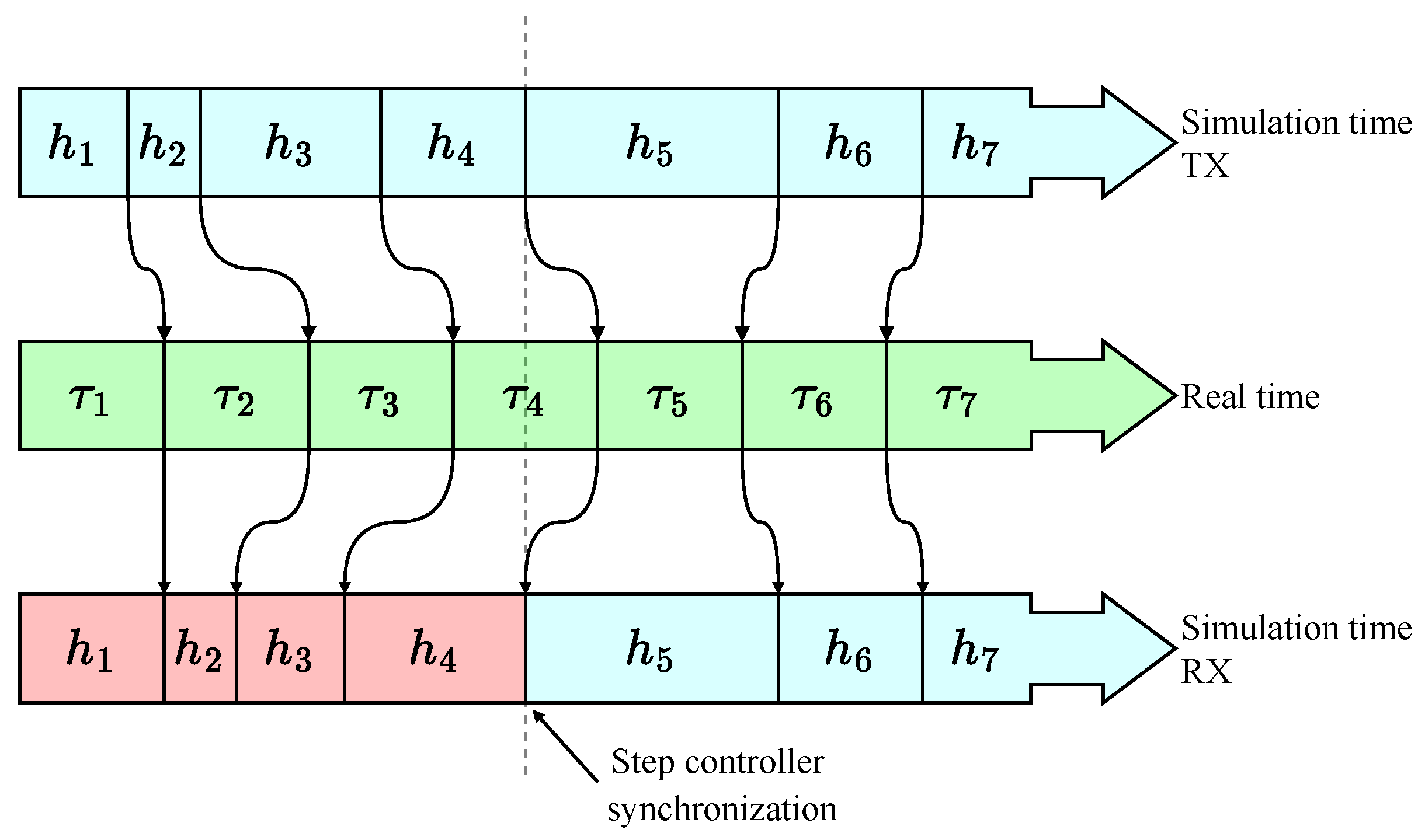
On the transmitter side, the discrete signal is generated with a variable step, but it cannot be transmitted with a variable step in real time because in digital systems, only constant-rate sampling is generally possible. Interpolation of a variable-step solution to a constant step will cause information loss, and the receiver will not be able to recover the message. Thus, the following scheme is proposed; see Figure 4. There, three-time axes are presented: for the transmitter variable, steps h i ; for the real-time variable, steps τ i ; and for the receiver variable, time h j . The signal is transmitted as if the intervals h i correspond to the intervals τ i . Due to the fact that on the receiver side, the step controller selects steps similar to those of h i , if the parameters t o l match, the systems can synchronize with high accuracy. In real time, this modulation appears as a slight compression and stretching of the signal in phase, which, as will be shown later, contributes to the increased resistance to noise in the channel.

2.6. The Quantified Return Map Analysis

A quantified return map analysis (QRMA) is a method proposed in [43] and developed in [39] which can be used to find small differences in signals of a complex form, e.g., chaotic. It is based on the return map concept [44], which consists of finding the peaks and valleys of a signal and mapping them onto a two-dimensional plane. The amplitude, or the amplitude–phase distribution, of local extrema may be taken into account during this process. Amplitude return maps use arrays of the peak values (amplitudes) X m and X m + 1 and valleys Y m and Y m + 1 of a signal to map them onto a two-dimensional plane:
A = X m + Y m 2 , B = X m Y m , C = X m + 1 + Y m 2 , D = X m + 1 Y m .
The arrays are taken without the first element. The A and C arrays obtained are used as point coordinates along the horizontal axis, while B and D are along the vertical axis.
In the amplitude–phase variant of the algorithm, the A and C arrays are calculated accounting for the time distribution:
A = Δ T p e a k s + 1 Δ T p e a k s , B = X m .
where Δ T p e a k s + 1 is an array of the peak times without the first element, and Δ T p e a k s is an array of the peak times without the last element. Figure 5 presents an example of finding the local maxima to construct a phase return map.
The quantification method is based on representing the plane of the return maps as a two-dimensional histogram. For the estimated waveform segments corresponding to binary symbols ‘0’ and ‘1’, the difference between the histograms is calculated, and the percentage of mismatched areas is estimated [43]:
θ ( x ) = x x ϵ 0 x < ϵ ϵ N 1 , Δ i , j = | X i , j Y i , j | | Θ ( X i , j ) Θ ( Y i , j ) | , i , j [ 1 , N ] , D = i = 1 N j = 1 N θ ( Δ i , j ) θ ( X i , j ) + θ ( Y i , j ) .
where Θ is the Heaviside step function, N ( N × N ) is the 2D histogram resolution, and ϵ is a threshold for filtering out infrequent points that may eventually affect the value of the difference between the two return maps. Thresholding reduces the sensitivity of the QRMA to noise, as well as to various anti-RMA countermeasures, such as return map blurring [45].

3. Results

3.1. The Simulation Setup

All of the numerical experimental results were obtained using the the following simulation setup: the initial conditions for the master system X m ( 0 ) = [ 0.1 ; 0 ; 0 ] ; the initial conditions for both slave systems X s ( 0 ) = [ 1.1 ; 1 ; 1 ] ; the modulated parameters t o l 1 = 4 · 10 6 and t o l 2 = 6 · 10 6 ; the maximal integration time step h m a x = 0.5 ; the minimal integration time step h m a x = 0.001 ; the initial integration time step h 0 = 0.01 ; the extrapolation sequence { 1 , 2 , 3 } ; the bit transmission time τ = 15 s; and the transient time for the master and slave before modulation T T = 500 s.

3.2. The Influence of the Symmetry Distortion Coefficient on the ODE Dynamics

The discrete models obtained using MCD methods demonstrate rich dynamical properties. For example, if the value of the perversion coefficient s is large enough, then the resulting dynamic will also be affected. The order of the composition method also affects the resulting dynamics.
Figure 6 demonstrates the dynamical behavior of the Sprott Case S chaotic system under varying values for the symmetry distortion coefficient s . The figure comprises three main components: a bifurcation diagram, a plot of the largest Lyapunov exponent (LLE), and phase portraits. The bifurcation diagram shows the transitions between periodic and chaotic regimes as s changes, with the horizontal axis representing s and the vertical axis depicting the local maxima of the third state variable z m a x . The LLE plot next to the bifurcation diagram quantifies the degree of chaos, where positive values indicate chaotic dynamics. The phase portraits depict the structure of the system’s attractor in the x z phase space for specific s values, revealing how the symmetry distortion alters the geometry of the chaotic attractor.

3.3. The Bifurcation Diagrams and s-h Diagrams

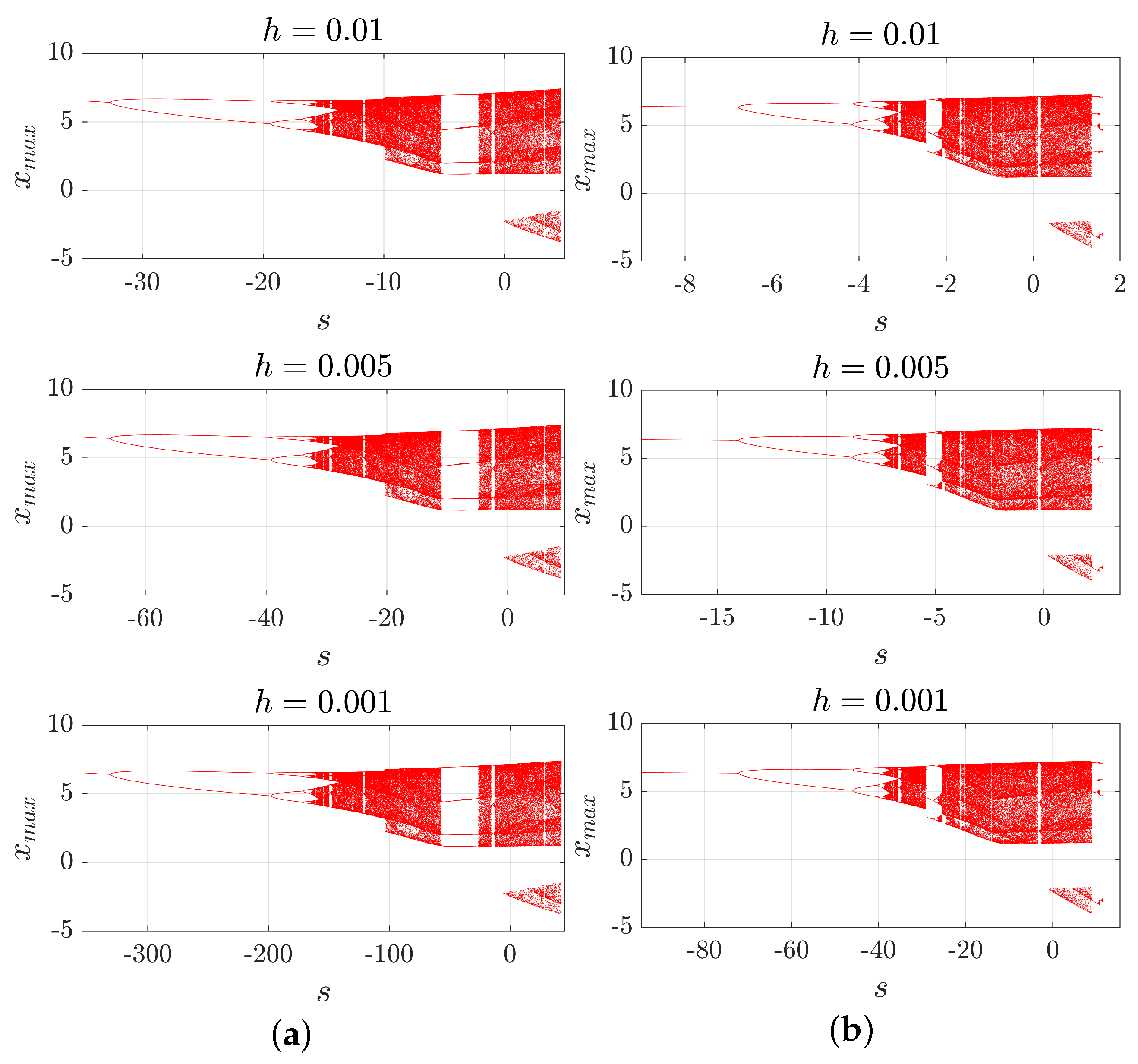
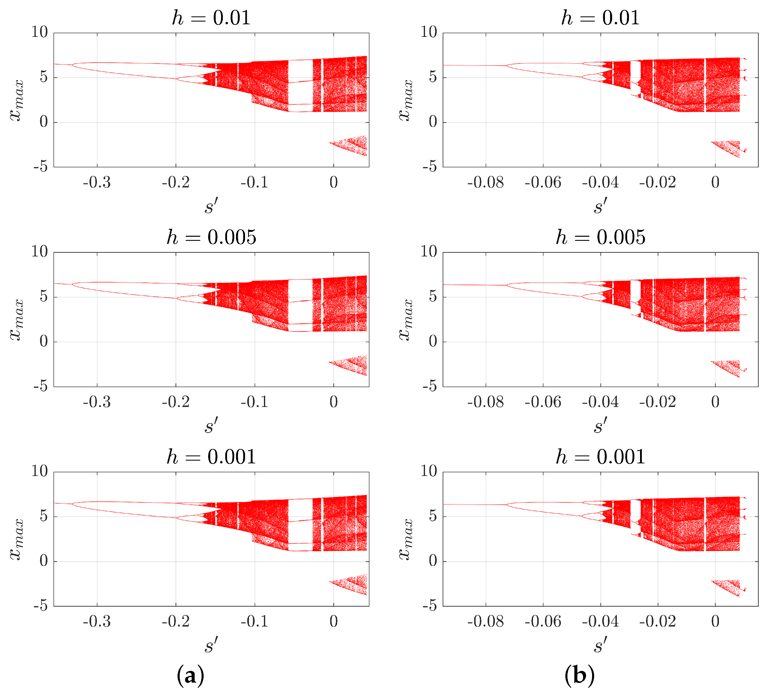
In the following Figure 7 and Figure 8, with a numerical example, we show that the use of the CD method with the variable symmetry coefficient s requires the selection of s at each integration step value h to keep the same dynamical regime, while the use of the symmetry distortion coefficient s does not create such dependence. Although it is clear from definitions (4) and (6), we will provide the corresponding bifurcation diagrams for the sake of clarity.
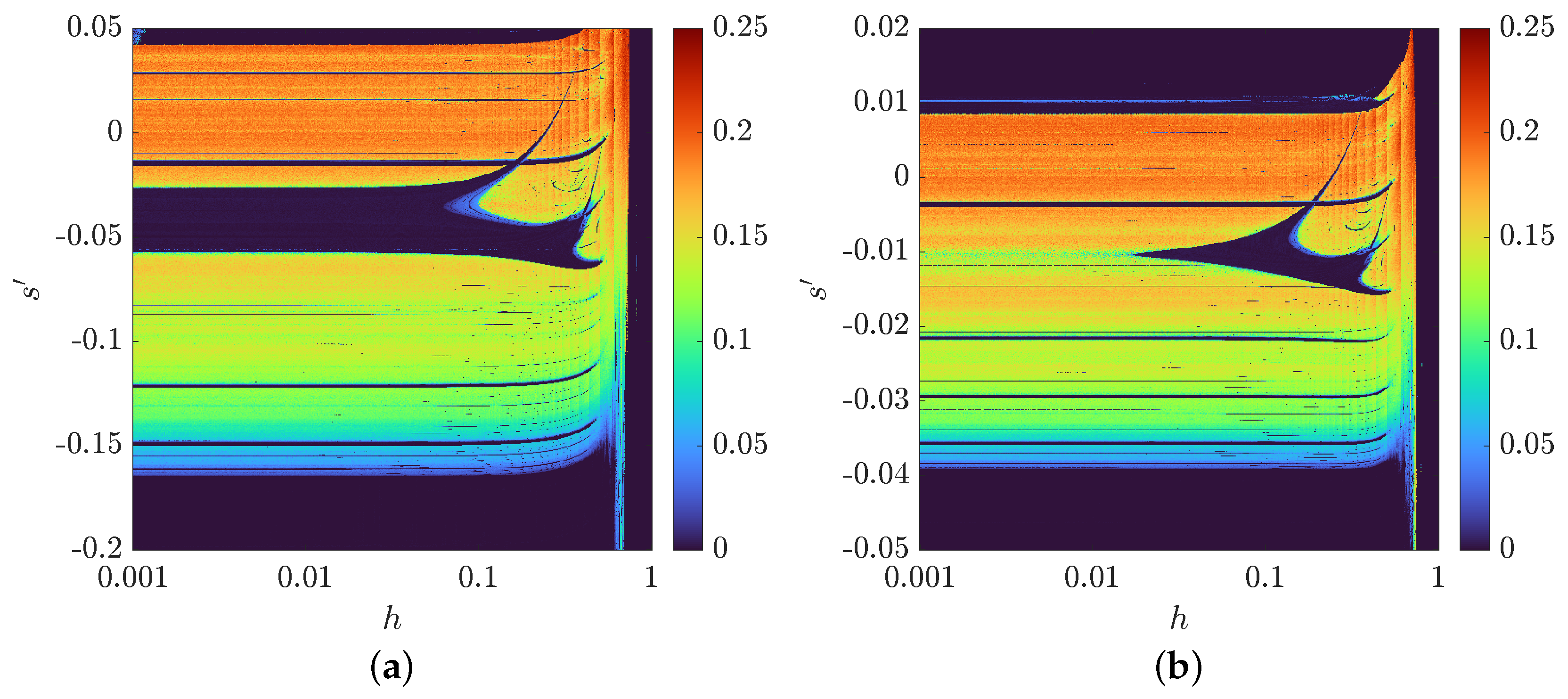
Figure 9 shows a 2D bifurcation diagram with respect to the step size h and the coefficient s for two cases: a finite-difference scheme in version (5) and in its permuted version:
Ψ h = Φ h 2 Φ h 1 * .
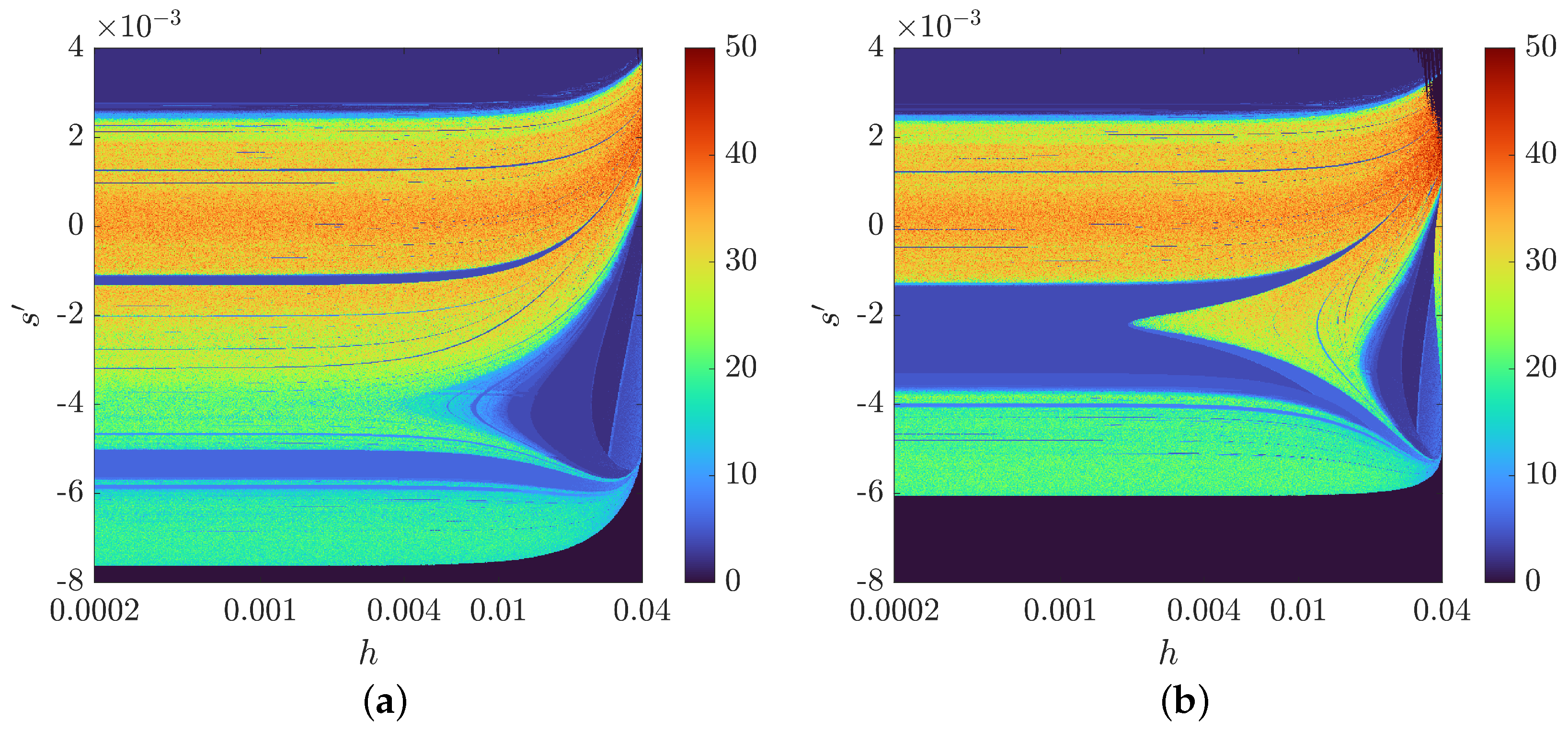
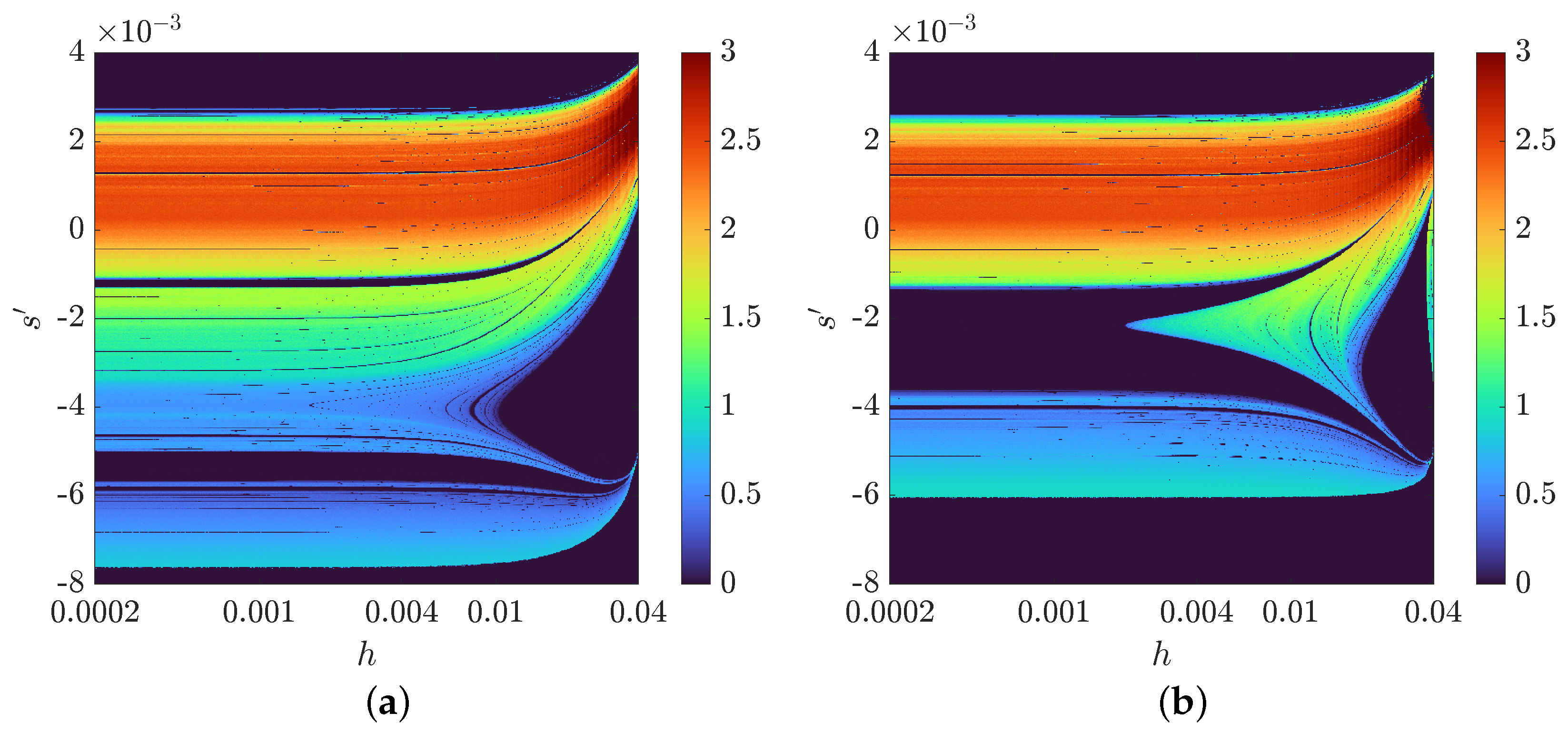
In Figure 9a, we used the first proposed variant (5), i.e., when implicitness occurred in the second half. In Figure 9b, instead of Φ h 1 , we used Φ h 1 * , and vice versa; instead of Φ h 2 * , we used Φ h 2 ; see (21). The color denotes the number of orbits obtained using the DBSCAN clustering algorithm [46]: black regions correspond to the absence of oscillations, blue regions correspond to periodic oscillations, and orange regions correspond to regions with developed chaotic motion. When s = 0 , the method is symmetric, and these lines are equal in both diagrams. Other values lead to the distortion of symmetry and thus changes in the dynamics. When the integration step is relatively small, there is no change in the dynamics for each value of s . Also, we can observe regions of parameter values where dynamic changes occur due to discretization with a relatively large integration step. Two-dimensional largest Lyapunov exponent (2D LLE) diagrams for the Case S system are shown in Figure 10.
The same analysis provided for the Chen system is presented in Appendix A. The analysis of Chen’s system is given for generality so that the reader can confirm that the observations found in the study of the Sprott Case S system are similarly found for Chen’s system.

3.4. A Variable-Time-Step Approach to Coherent Chaotic Communication

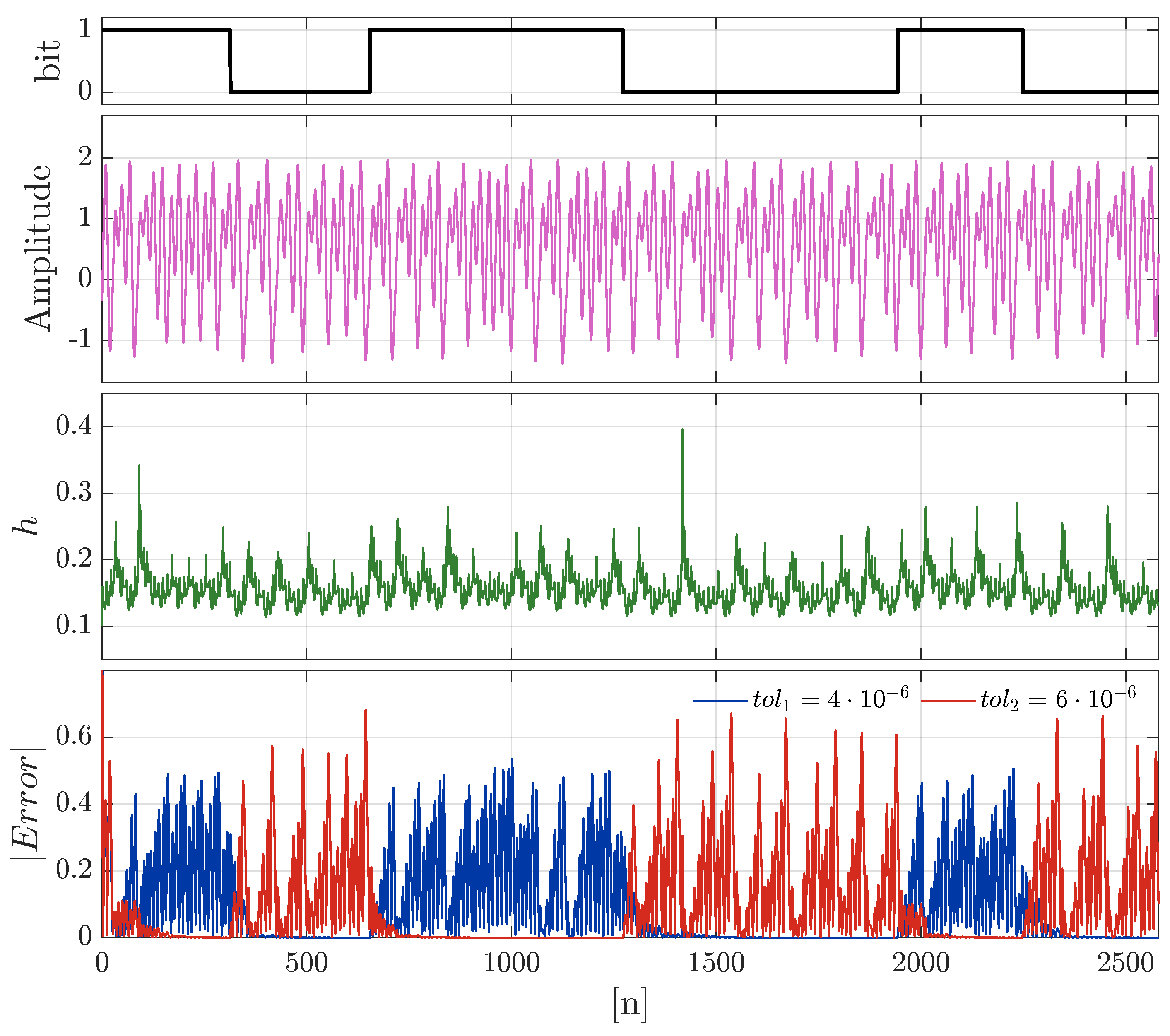
Figure 11 presents the time series of a message transmission process and the synchronization errors of the two systems on the receiver side. Recall that the value of the step controller t o l is used as the modulation parameter. One can see that visually, the transmission of information in a chaotic carrier cannot be identified, and high-precision analysis methods are needed to detect the very fact of transmission.

3.5. Privacy and Noise Tolerance Analysis

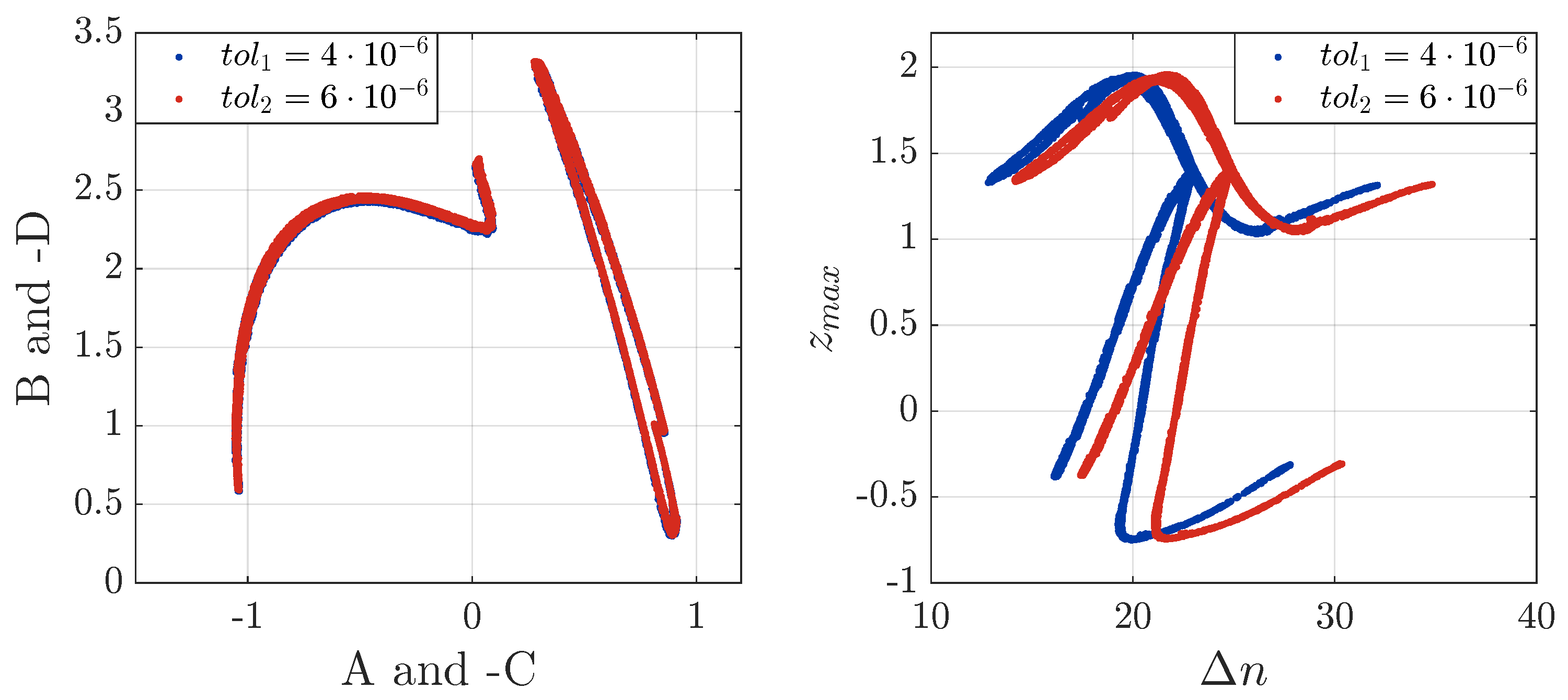
Let us investigate the properties of the developed chaotic communication system. Above, in (19) and Figure 5, we have shown how to calculate the return map based on the local maxima and inter-peak intervals. Figure 12 (the left part) shows that the classical return map analysis is not efficient. The reason for this is that the proposed modulation method is a kind of phase modulation and has no influence on the amplitude. In contrast, the right-hand plot in Figure 12 shows the effectiveness of the phase return map in reliably distinguishing between chaotic waveforms generated with a given difference in the t o l parameter and in the absence of noise.
Below, numerical estimations of the phase return map analysis (QRMA)’s effectiveness, as well as the tolerance to noise in the channel, are presented; see Figure 13. The figure shows two plots that compare the dependence of the bit error rate (BER) and the QRMA on the signal-to-noise ratio (SNR).
The left part of Figure 13 shows how the BER changes as a function of the SNR. As the SNR increases, the BER decreases, indicating an improvement in the quality of data transmission. It can be seen that changing the parameter Δ t o l (the difference in the parameter values when transmitting the binary symbols ‘0’ and ‘1’) by a factor of 2 leads to a decrease in the BER by 10%, which becomes critical at an SNR below 15–20 dB. Note that a BER above 10% is impractical, as it can hardly be corrected with self-repairing coding. With that, at an SNR = 25 dB bit errors do not occur.
The plot of the QRMA vs. the SNR shows how the privacy (estimated by the QRMA metric) varies with the SNR. Increasing the noise in the signal leads to a higher transmission confidentiality, which is consistent with previous research but stays in clear contradiction to the transmission quality in terms of the BER. Here, changing the parameter Δ t o l by a factor of 2 leads to a decrease in privacy by about 20%, which can be significant.
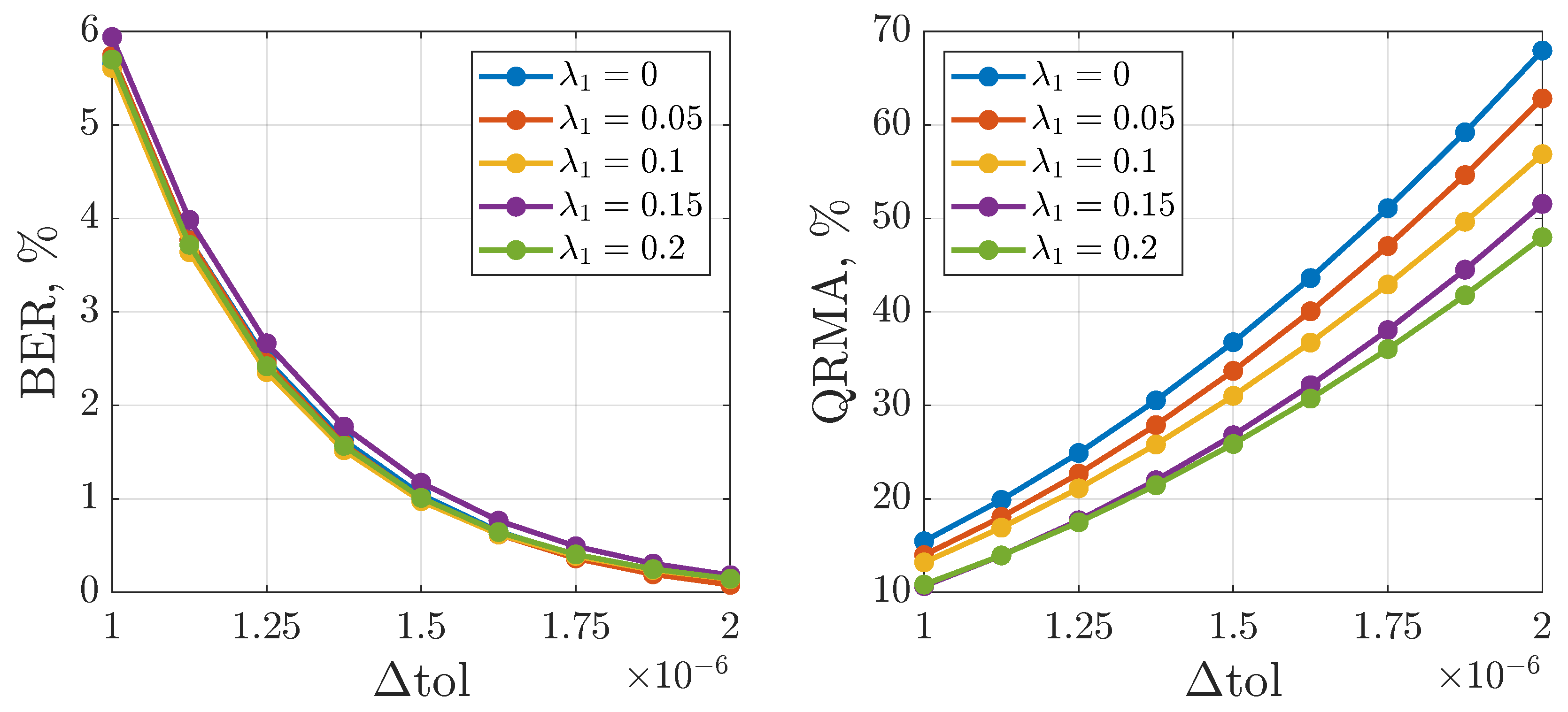
As the parameters in Figure 14, we chose the values of the largest Lyapunov exponent, denoted as λ , to test the hypothesis that a higher LLE value improves the performance of the chaotic communication system. And this is indeed observed.
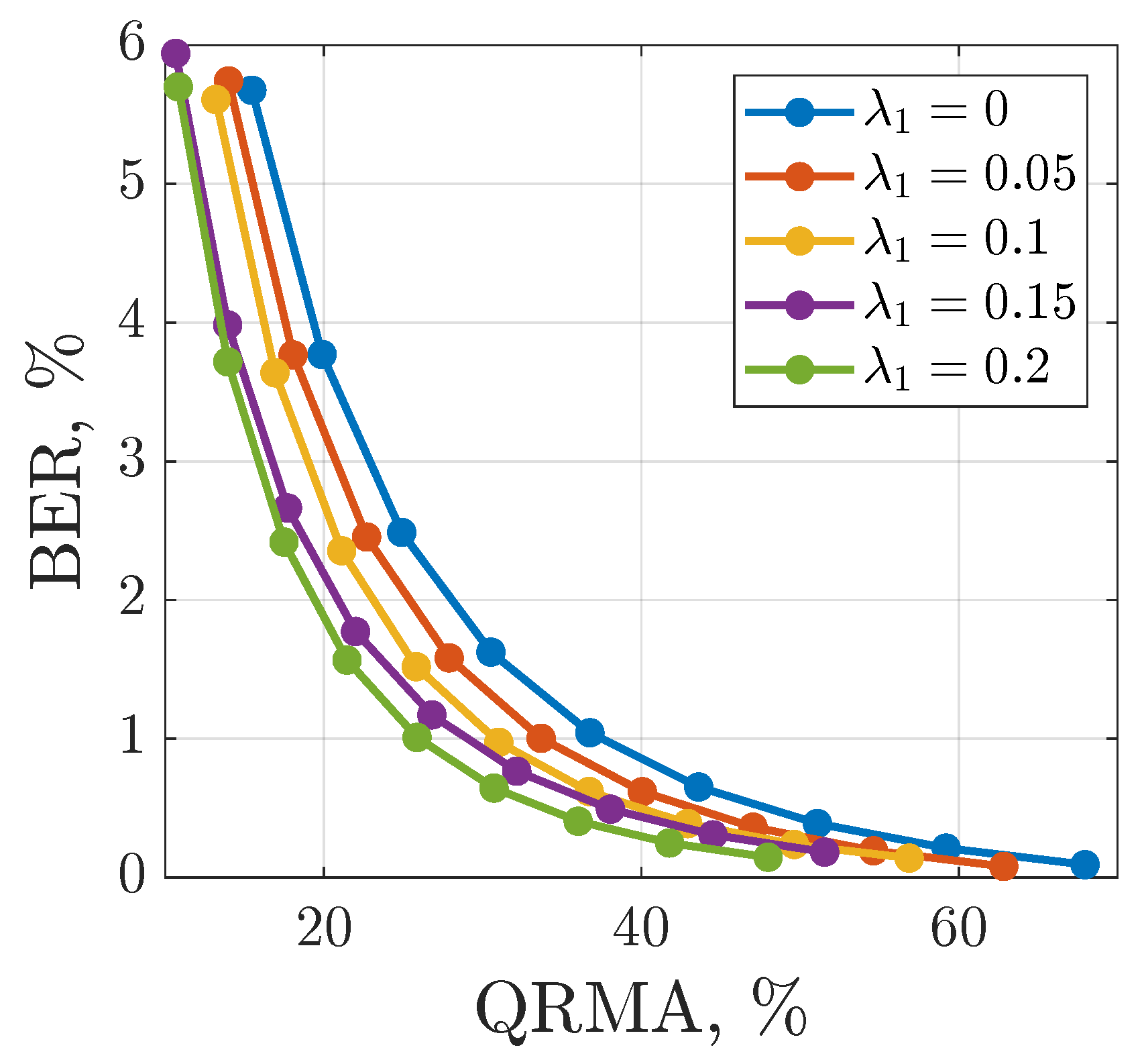
In addition to the obvious improvement in quality with an increased Δ t o l (a decreased BER) and increased privacy (an improved QRMA), selecting system parameters that provide a higher LLE value can also improve the performance of the system by about a percent in the sense of the BER and by about 10% in the sense of the QRMA. An LLE value = 0 corresponds to a periodic regime, while an LLE = 0.2 corresponds to developed chaos. The value of symmetry distortion s according to Figure 6 was chosen as the parameter with which to vary the LLE.
For specific practical applications, it makes sense to construct a Pareto front which allows us to choose the parameters of the transmitter according to both criteria, noise immunity and privacy; see Figure 15. This plot presents straightforward confirmation that increasing the chaos measure (LLE) reduces the BER and simultaneously increases the privacy.
To summarize the results obtained using different modulation methods and compare the proposed method with them, Figure 16 is provided. As one can see, the results of the developed modulation method significantly overcome those previously published. Variable-step modulation optimized for noise resistance shows an almost zero BER with the QRMA estimate lower than the values for PM, SCM, and VMPM at any level of BER.

4. Conclusions

This study introduced a novel variable-step modified composite diagonal (VS-MCD) numerical integration method. Its key feature is the symmetry distortion coefficient s , which, unlike in the classical CD method, is independent of the step size, allowing for seamless integration with variable-step controllers like the Hairer controller. This approach enhances the precision of reproducing the system dynamics without compromising stability or accuracy, which is useful for many practical applications, e.g., for chaos-based communications.
We applied the VS-MCD method to a chaos-based communication system based on the Sprott Case S oscillator, using the tolerance parameter t o l as a modulation parameter to embed binary messages into chaotic signals. This method improves the privacy by expanding the key space and enhances the noise resistance because the tolerance modulation is a kind of phase modulation, and the change in the amplitude of the transmitted signal in the presence of noise in the channel has a minor impact on the quality of transmission. Numerical experiments show that increasing Δ t o l two times reduced the BER by 10% at a low SNR (<20 dB) and increased the transmission secrecy estimated using a quantified return map analysis (QRMA) by approximately 20%. The system achieved a near-zero BER at SNR levels above 25 dB, which is a superior result in comparison to those of other similar modulation techniques, and also showed lower QRMA values at the same SNR level. Also, we found that choosing the system parameters to provide higher largest Lyapunov exponents (LLE = 0.2) improved the overall communication system’s performance, with a 10% decrease in the QRMA estimate and a slight improvement in the BER.
Future research will focus on the methodology for selecting the optimal system parameters, integrating it with other modulation techniques, and the hardware implementation.

Author Contributions

Conceptualization: V.R. and T.K. Data curation: A.M. and Y.B. Formal analysis: Y.B. Funding acquisition: T.K. Investigation: V.R. and I.B. Methodology: V.R. and T.K. Project administration: T.K. Resources: A.M. Software: V.R., I.B. and M.G. Supervision: T.K. Validation: A.M. and Y.B. Visualization: M.G. Writing—original draft: V.R. and I.B. Writing—review and editing: A.M., Y.B. and M.G. All authors have read and agreed to the published version of the manuscript.

Funding

This study was supported by the grant of the Russian Science Foundation (RSF), project 20-79-10334.

Data Availability Statement

The original contributions presented in this study are included in the article. Further inquiries can be directed to the corresponding author(s).

Conflicts of Interest

The authors declare no conflicts of interest.

Abbreviations

The following abbreviations are used in this manuscript:
BERBit error rate
CDComposite diagonal (method)
CCSChaotic communication system
CSKChaotic shift keying
DCCSDirect chaotic communication system
DOFDegree of freedom
FDSFinite-difference scheme
LLELargest Lyapunov exponent
ODEOrdinary differential equation
PMParameter modulation
SCMSymmetry coefficient modulation
SNRSignal-to-noise ratio
VMPMVariable-step parameter modulation
VS-MCDVariable-step modified composite diagonal (method)
QRMAQuantified return map analysis

Appendix A. A Study on the Dynamics of the Chen System Implemented Using the VS-MCD Method
The Chen system resembles the classical Lorenz attractor and also exhibits complex chaotic behavior. This system is widely used as a model to study chaotic phenomena. e.g., in the field of chaotic communications [48,49,50], chaos control [51,52] and others. The ODE for the Chen system is as follows:
x ˙ = α ( y x ) , y ˙ = ( c α ) x x z + c y , z ˙ = x y β z .
The typical parameter values are α = 35 , β = 3 , c = 28 . The system has one trivial and two non-trivial equilibrium points. The finite-difference scheme for the Chen system obtained using the MCD method is as follows:
x n + s = x n + h 1 α ( y n x n ) , y n + s = y n + h 1 ( c α ) x n + s x n + s z n + c y n , z n + s = z n + h 1 x n + s y n + s β z n , z n + 1 = z n + s + h 2 x n + s y n + s 1 + h 2 β , y n + 1 = y n + s + h 2 x n + s c α z n + 1 1 h 2 c , x n + 1 = x n + s + h 2 α y n + 1 1 + h 2 α .
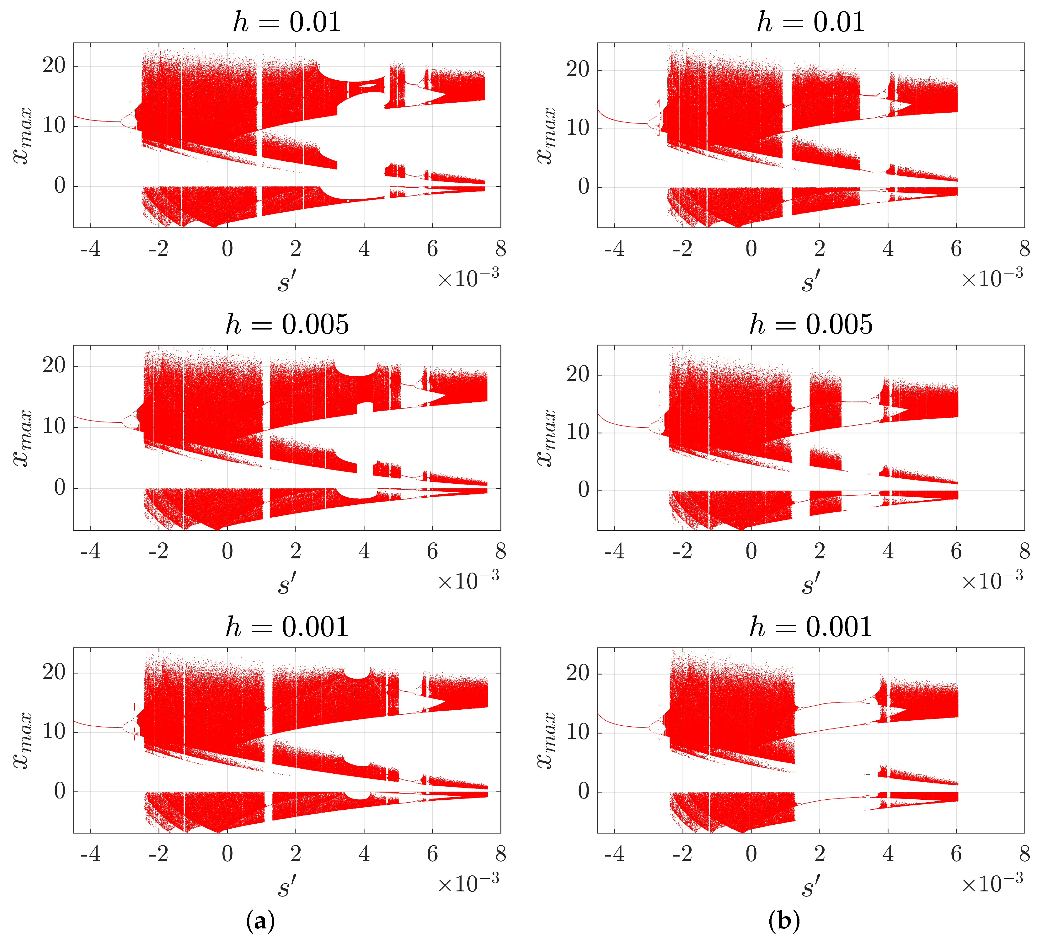
In Figure A1, we show through a numerical example that the use of the symmetry distortion coefficient s demonstrates the minor dependence of the system dynamics on the integration step, and the order of self-adjoint half calculation is more critical.
Figure A2 shows a 2D bifurcation diagram with respect to the step size h and the coefficient s for two cases: a finite-difference scheme in version (1) and its permuted version. The color denotes the number of orbits obtained using the DBSCAN clustering algorithm: black regions correspond to the absence of periodicity in movement, blue regions correspond to periodic oscillations, and orange regions correspond to regions with developed chaotic motion. When s = 0 , the method is symmetric, and these lines are equal in both diagrams. Other values lead to the distortion of symmetry and thus changes in the dynamics. Two-dimensional largest Lyapunov exponent (2D LLE) diagrams for the Chen system are shown in Figure A3.
Figure A1. Bifurcation diagrams with respect to the parameter s for the Chen system. (a) An implicit in the second half. (b) An implicit in the first half.
Mathematics 13 01229 g0a1
Figure A2. Two-dimensional bifurcation diagram with respect to the parameters h and s for the Chen system. (a) An implicit in the second half. (b) An implicit in the first half.
Mathematics 13 01229 g0a2
Figure A3. Two-dimensional LLE diagrams with respect to the parameters h and s for the Chen system. (a) An implicit in the second half. (b) An implicit in the first half.
Mathematics 13 01229 g0a3

References

  1. Timberlake, T.; Hasbun, J.E. Computation in classical mechanics. Am. J. Phys. 2008, 76, 334–339. [Google Scholar] [CrossRef]
  2. Hairer, E.; Lubich, C. Long-term analysis of the Störmer–Verlet method for Hamiltonian systems with a solution-dependent high frequency. Numer. Math. 2016, 134, 119–138. [Google Scholar] [CrossRef]
  3. Yang, B.; Wang, Z.; Tian, H.; Liu, J. Symplectic dynamics and simultaneous resonance analysis of memristor circuit based on its van der Pol oscillator. Symmetry 2022, 14, 1251. [Google Scholar] [CrossRef]
  4. Nørsett, S.P. Semi-Explicit Runge-Kutta Methods; Department of Mathematics, University of Trondheim: Trondheim, Norway, 1974. [Google Scholar]
  5. Alexander, R. Diagonally implicit Runge–Kutta methods for stiff ODE’s. SIAM J. Numer. Anal. 1977, 14, 1006–1021. [Google Scholar] [CrossRef]
  6. Zhang, H.; Qian, X.; Song, S. Novel high-order energy-preserving diagonally implicit Runge–Kutta schemes for nonlinear Hamiltonian ODEs. Appl. Math. Lett. 2020, 102, 106091. [Google Scholar] [CrossRef]
  7. Diele, F.; Marangi, C. Explicit symplectic partitioned Runge–Kutta–Nyström methods for non-autonomous dynamics. Appl. Numer. Math. 2011, 61, 832–843. [Google Scholar] [CrossRef]
  8. Wolke, R.; Knoth, O. Implicit–explicit Runge–Kutta methods applied to atmospheric chemistry-transport modelling. Environ. Model. Softw. 2000, 15, 711–719. [Google Scholar] [CrossRef]
  9. Rousseau, G.; Kapral, R. Asynchronous algorithm for integration of reaction–diffusion equations for inhomogeneous excitable media. Chaos Interdiscip. J. Nonlinear Sci. 2000, 10, 812–825. [Google Scholar] [CrossRef]
  10. Shi, Y.; Green, W.H.; Wong, H.W.; Oluwole, O.O. Accelerating multi-dimensional combustion simulations using GPU and hybrid explicit/implicit ODE integration. Combust. Flame 2012, 159, 2388–2397. [Google Scholar] [CrossRef]
  11. Tunc, H.; Sari, M. A new implicit-explicit local method to capture stiff behavior with covid-19 outbreak application. arXiv 2021, arXiv:2104.05817. [Google Scholar]
  12. Butusov, D.N.; Ostrovskii, V.Y.; Karimov, A.I.; Andreev, V.S. Semi-explicit composition methods in memcapacitor circuit simulation. Int. J. Embed. Real-Time Commun. Syst. (IJERTCS) 2019, 10, 37–52. [Google Scholar] [CrossRef]
  13. Butusov, D.; Tutueva, A.; Fedoseev, P.; Terentev, A.; Karimov, A. Semi-implicit multistep extrapolation ODE solvers. Mathematics 2020, 8, 943. [Google Scholar] [CrossRef]
  14. Burden, R.L.; Faires, J.D. 2.2 fixed-point iteration. In Numerical Analysis, 3rd ed.; PWS Publishers: Boston, MA, USA, 1985; p. 64. [Google Scholar]
  15. Holder, T.; Leimkuhler, B.; Reich, S. Explicit variable step-size and time-reversible integration. Appl. Numer. Math. 2001, 39, 367–377. [Google Scholar] [CrossRef]
  16. Butusov, D.; Rybin, V.; Karimov, A. Fast time-reversible synchronization of chaotic systems. Phys. Rev. E 2025, 111, 014213. [Google Scholar] [CrossRef]
  17. Tutueva, A.; Butusov, D. Avoiding dynamical degradation in computer simulation of chaotic systems using semi-explicit integration: Rössler oscillator case. Fractal Fract. 2021, 5, 214. [Google Scholar] [CrossRef]
  18. Shi, H.; Fan, S.; Xing, W.; Sun, J. Study of weak vibrating signal detection based on chaotic oscillator in MEMS resonant beam sensor. Mech. Syst. Signal Process. 2015, 50, 535–547. [Google Scholar] [CrossRef]
  19. Fiderer, L.J.; Braun, D. Quantum metrology with quantum-chaotic sensors. Nat. Commun. 2018, 9, 1351. [Google Scholar] [CrossRef]
  20. Karimov, T.; Druzhina, O.; Karimov, A.; Tutueva, A.; Ostrovskii, V.; Rybin, V.; Butusov, D. Single-coil metal detector based on spiking chaotic oscillator. Nonlinear Dyn. 2022, 107, 1295–1312. [Google Scholar] [CrossRef]
  21. Estudillo-Valdez, M.A.; Adeyemi, V.A.; Tlelo-Cuautle, E.; Sandoval-Ibarra, Y.; Nuñez-Perez, J.C. FPGA realization of four chaotic interference cases in a terrestrial trajectory model and application in image transmission. Sci. Rep. 2023, 13, 12969. [Google Scholar] [CrossRef]
  22. Zolfaghari, B.; Koshiba, T. Chaotic image encryption: State-of-the-art, ecosystem, and future roadmap. Appl. Syst. Innov. 2022, 5, 57. [Google Scholar] [CrossRef]
  23. Luo, W.; Cui, Y. Signal denoising based on Duffing oscillators system. IEEE Access 2020, 8, 86554–86563. [Google Scholar] [CrossRef]
  24. Michel, L.; Ghanes, M.; Plestan, F.; Aoustin, Y.; Barbot, J.P. A noise less-sensing semi-implicit discretization of a homogeneous differentiator: Principle and application. In Proceedings of the 2021 European Control Conference (ECC), Delft, The Netherlands, 29 June–2 July 2021; IEEE: Piscataway, NJ, USA; 2021; pp. 2340–2345. [Google Scholar]
  25. Eisencraft, M.; Fanganiello, R.; Grzybowski, J.; Soriano, D.; Attux, R.; Batista, A.; Macau, E.; Monteiro, L.H.A.; Romano, J.; Suyama, R.; et al. Chaos-based communication systems in non-ideal channels. Commun. Nonlinear Sci. Numer. Simul. 2012, 17, 4707–4718. [Google Scholar] [CrossRef]
  26. Kaddoum, G. Wireless chaos-based communication systems: A comprehensive survey. IEEE Access 2016, 4, 2621–2648. [Google Scholar] [CrossRef]
  27. Yuningsih, S.H.; Supian, S.; Sukono, S.; Subiyanto, S. Wireless chaos-based communication system: Literature Review. Int. J. Quant. Res. Model. 2021, 2, 46–54. [Google Scholar] [CrossRef]
  28. Pisarchik, A.N.; Jaimes-Reátegui, R.; Rodríguez-Flores, C.; García-López, J.; Huerta-Cuéllar, G.; Martín-Pasquín, F.J. Secure chaotic communication based on extreme multistability. J. Frankl. Inst. 2021, 358, 2561–2575. [Google Scholar] [CrossRef]
  29. Burkin, I.; Kuznetsova, O. An approach to generating extremely multistable chaotic systems. J. Math. Sci. 2022, 262, 779–789. [Google Scholar] [CrossRef]
  30. Capligins, F.; Babajans, R.; Cirjulina, D.; Kolosovs, D.; Litvinenko, A. Frequency-modulated antipodal Chaos Shift Keying Chaotic Communication on Field Program Gate Array: Prototype Design and Performance Insights. Appl. Sci. 2025, 15, 1156. [Google Scholar] [CrossRef]
  31. Cirjulina, D.; Babajans, R.; Kolosovs, D. Experimental Study on Quadrature Chaos Shift Keying Communication System. In Proceedings of the 2024 IEEE Workshop on Microwave Theory and Technology in Wireless Communications (MTTW), Riga, Latvia, 2–4 October 2024; IEEE: Piscataway, NJ, USA; 2024; pp. 29–32. [Google Scholar]
  32. Cirjulina, D.; Babajans, R.; Capligins, F.; Litvinenko, A. Experimental Study on Colpitts Chaotic Oscillator-Based Communication System Application for the Internet of Things. Appl. Sci. 2024, 14, 1180. [Google Scholar] [CrossRef]
  33. Cirjulina, D.; Babajans, R.; Kolosovs, D. Design particularities of quadrature chaos shift keying communication system with enhanced noise immunity for IoT applications. Entropy 2025, 27, 296. [Google Scholar] [CrossRef]
  34. Rybin, V.; Karimov, T.; Bayazitov, O.; Kvitko, D.; Babkin, I.; Shirnin, K.; Kolev, G.; Butusov, D. Prototyping the symmetry-based chaotic communication system using microcontroller unit. Appl. Sci. 2023, 13, 936. [Google Scholar] [CrossRef]
  35. Pecora, L.M.; Carroll, T.L. Synchronization in chaotic systems. Phys. Rev. Lett. 1990, 64, 821. [Google Scholar] [CrossRef] [PubMed]
  36. Hairer, E.; Norsett, S.; Wanner, G. Solving Ordinary Differential Equations I: Nonstiff Problems; Springer: Berlin/Heidelberg, Germany, 1993; Volume 8. [Google Scholar] [CrossRef]
  37. Cuomo, K.M.; Oppenheim, A.V. Chaotic signals and systems for communications. In Proceedings of the 1993 IEEE International Conference on Acoustics, Speech, and Signal Processing, Minneapolis, MN, USA, 27–30 April 1993; IEEE: Piscataway, NJ, USA; 1993; Volume 3, pp. 137–140. [Google Scholar]
  38. Karimov, T.; Rybin, V.; Kolev, G.; Rodionova, E.; Butusov, D. Chaotic communication system with symmetry-based modulation. Appl. Sci. 2021, 11, 3698. [Google Scholar] [CrossRef]
  39. Babkin, I.; Rybin, V.; Andreev, V.; Karimov, T.; Butusov, D. Coherent Chaotic Communication Using Generalized Runge–Kutta Method. Mathematics 2024, 12, 994. [Google Scholar] [CrossRef]
  40. Hairer, E.; Lubich, C.; Wanner, G. Geometric numerical integration illustrated by the Störmer–Verlet method. Acta Numer. 2003, 12, 399–450. [Google Scholar] [CrossRef]
  41. Sprott, J.C. Some simple chaotic flows. Phys. Rev. E 1994, 50, R647. [Google Scholar] [CrossRef]
  42. Chen, G.; Ueta, T. Yet another chaotic attractor. Int. J. Bifurc. Chaos 1999, 9, 1465–1466. [Google Scholar] [CrossRef]
  43. Rybin, V.; Butusov, D.; Rodionova, E.; Karimov, T.; Ostrovskii, V.; Tutueva, A. Discovering chaos-based communications by recurrence quantification and quantified return map analyses. Int. J. Bifurc. Chaos 2022, 32, 2250136. [Google Scholar] [CrossRef]
  44. Pérez, G.; Cerdeira, H.A. Extracting messages masked by chaos. Phys. Rev. Lett. 1995, 74, 1970. [Google Scholar] [CrossRef]
  45. Li, S.; Chen, G.; Alvarez, G. Return-map cryptanalysis revisited. Int. J. Bifurc. Chaos 2006, 16, 1557–1568. [Google Scholar] [CrossRef]
  46. Hou, G.; Wang, J.; Fan, Y. Wind power forecasting method of large-scale wind turbine clusters based on DBSCAN clustering and an enhanced hunter-prey optimization algorithm. Energy Convers. Manag. 2024, 307, 118341. [Google Scholar] [CrossRef]
  47. Rybin, V.; Butusov, D.; Babkin, I.; Pesterev, D.; Arlyapov, V. Some properties of a discrete Lorenz system obtained by variable midpoint method and its application to chaotic signal modulation. Int. J. Bifurc. Chaos 2024, 34, 2450009. [Google Scholar] [CrossRef]
  48. Jiang-Feng, X.; Le-Quan, M.; Guan-Rong, C. A Chaotic Communication Scheme Based on Generalized Synchronization and Hash Functions. Chin. Phys. Lett. 2004, 21, 1445. [Google Scholar] [CrossRef]
  49. Sadoudi, S.; Azzaz, M.S.; Djeddou, M.; Benssalah, M. An FPGA real-time implementation of the Chen’s chaotic system for securing chaotic communications. Int. J. Nonlinear Sci. 2009, 7, 467–474. [Google Scholar]
  50. Ali, N.M.; Jamal, R.K. A novel secure communication system using Chen’s chaotic model. Opt. Quantum Electron. 2022, 54, 641. [Google Scholar] [CrossRef]
  51. Li, C.; Chen, G. Chaos in the fractional order Chen system and its control. Chaos Solitons Fractals 2004, 22, 549–554. [Google Scholar] [CrossRef]
  52. Chen, S.; Yang, Q.; Wang, C. Impulsive control and synchronization of unified chaotic system. Chaos Solitons Fractals 2004, 20, 751–758. [Google Scholar] [CrossRef]
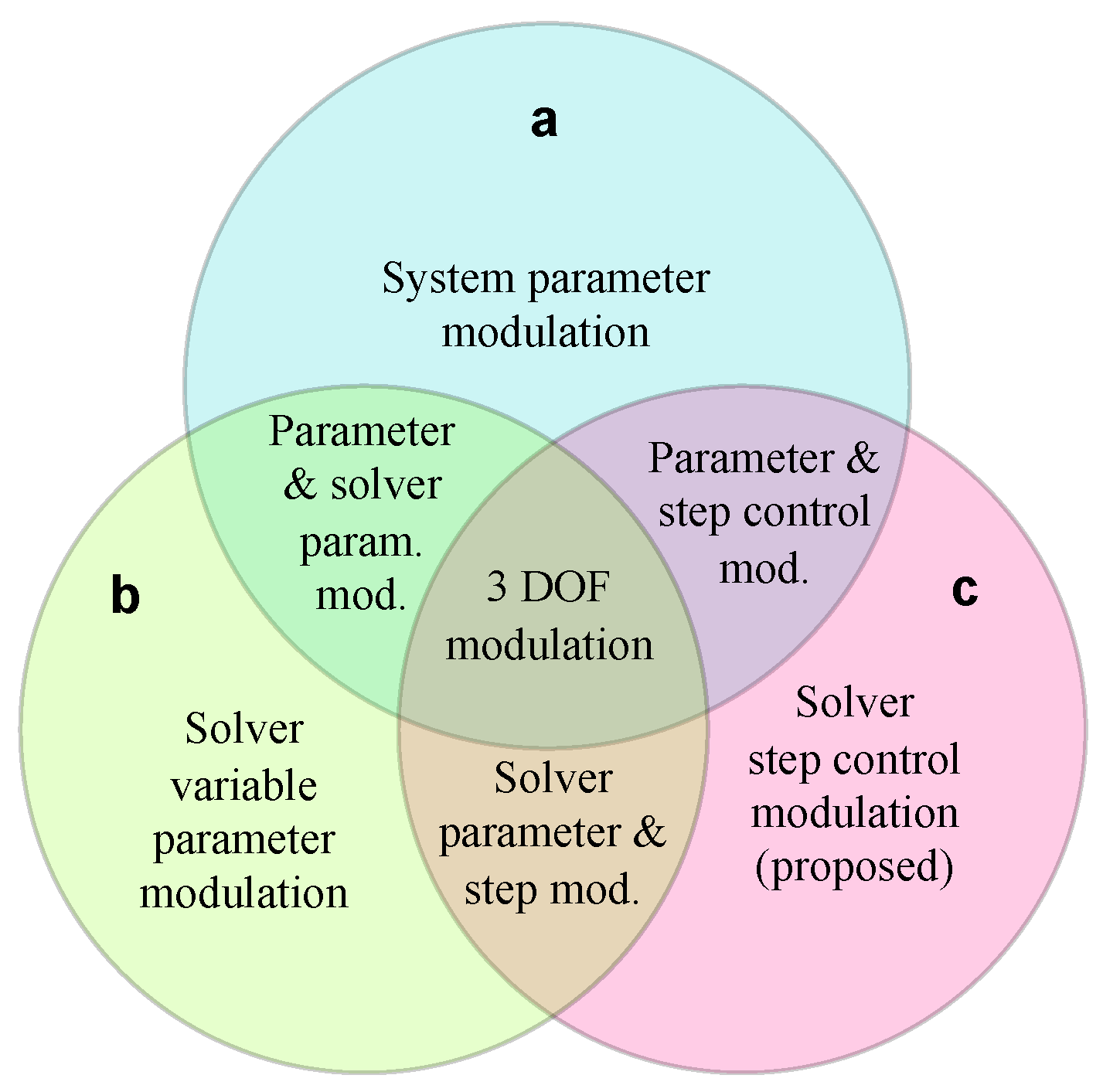
Figure 1. Family of modulation methods for digital direct chaotic communication systems and the location of the presented method: (a) bifurcation parameter modulation [37]; (b) solver variable parameter modulation, e.g., symmetry coefficient modulation (SCM) [38] and Runge–Kutta α parameter modulation [39]; (c) a proposed modulation scheme based on changing the settings of the variable-step solver.
Mathematics 13 01229 g001
Figure 2. Graphical representation of symmetry (s) and symmetry distortion ( s ) coefficients.
Mathematics 13 01229 g002
Figure 3. The proposed chaotic communication scheme.
Mathematics 13 01229 g003
Figure 4. Mapping between simulated and real-time values in the proposed communication system. The marked time point labels the establishment of synchronization between the step controllers on the receiver side and the transmitter side. After this moment, the same integration steps are set in both the TX and RX models. TX stands for the transmitter and RX for the receiver.
Mathematics 13 01229 g004
Figure 5. Example of a signal with the local peaks found used to form X m and X m + 1 and the inter-peak intervals Δ T p e a k s and Δ T p e a k s + 1 . Here, n denotes the number of discrete samples.
Mathematics 13 01229 g005
Figure 6. Bifurcation diagram, largest Lyapunov exponent (LLE) values, and phase portraits of Sprott Case S system with different symmetry distortion coefficient s values. Other system parameters are a = 4, b = 1. The color correlates with phase portraits above.
Mathematics 13 01229 g006
Figure 7. A bifurcation diagram with respect to the parameter s for the Case S system. (a) An implicit in the second half. (b) An implicit in the first half. The diagrams look similar, but the values of the parameter s at the horizontal axes are stretched at different step values.
Mathematics 13 01229 g007
Figure 8. A bifurcation diagram with respect to the parameter s for Case S system. (a) An implicit in the second half. (b) An implicit in the first half. The diagrams look almost similar, and the values of the parameter s on the horizontal axes are similar for different step values, depending primarily on the sequence of self-adjoint half calculation.
Mathematics 13 01229 g008
Figure 9. A 2D bifurcation diagram with respect to the parameters h and s for a Sprott Case S system. (a) An implicit in the second half. (b) An implicit in the first half.
Mathematics 13 01229 g009
Figure 10. A 2D LLE diagram with respect to the parameters h and s for a Case S system. (a) An implicit in the second half. (b) An implicit in the first half.
Mathematics 13 01229 g010
Figure 11. Example of transmitting a message using the proposed approach. The message ‘10110010’ is sent, which is seen in the upper plot. A chaotic signal with an embedded message is presented below, as well as an integration step and the synchronization error between the two systems on the receiver side, with different t o l parameters for the step controllers. A Sprott Case S oscillator with the standard parameters is used.
Mathematics 13 01229 g011
Figure 12. A classical amplitude return map (left) and phase return map for chaotic communication using variable-step modulation (right).
Mathematics 13 01229 g012
Figure 13. The BER and QRMA vs. the SNR for the proposed CSS.
Mathematics 13 01229 g013
Figure 14. BER vs. Δ t o l and QRMA vs. Δ t o l estimation.
Mathematics 13 01229 g014
Figure 15. QRMA vs. BER estimation for different LLE values ( λ 1 ). The different points at each line correspond to the different SNR levels presented in Figure 14.
Mathematics 13 01229 g015
Figure 16. Comparison of the proposed modulation method with those previously published. Here, PM = parameter modulation [34], VMPM = variable mid-point modulation [47], SCM = symmetry coefficient modulation [34], VSM = variable-step modulation (this work). For each modulation type, two lines are presented, with the parameters optimized for a lower BER and a lower QRMA estimate, respectively. Different points on each line correspond to different SNR levels, as labeled in dB.
Mathematics 13 01229 g016
Disclaimer/Publisher’s Note: The statements, opinions and data contained in all publications are solely those of the individual author(s) and contributor(s) and not of MDPI and/or the editor(s). MDPI and/or the editor(s) disclaim responsibility for any injury to people or property resulting from any ideas, methods, instructions or products referred to in the content.