Article

Adaptive Approximate Predefined-Time Guaranteed Performance Control of Uncertain Spacecraft

Xi’an Key Laboratory of Intelligence, Xi’an Technological University, Xi’an 710021, China
*
Author to whom correspondence should be addressed.
Mathematics 2025, 13(5), 832; https://doi.org/10.3390/math13050832
Submission received: 13 February 2025 / Revised: 26 February 2025 / Accepted: 27 February 2025 / Published: 1 March 2025
(This article belongs to the Special Issue Finite-Time/Fixed-Time Stability and Control of Dynamical Systems)

Abstract

:
This brief tackles the predefined-time attitude tracking problem with guaranteed performance for rigid spacecraft subject to uncertain inertia, external disturbances, and actuator partial failure. Firstly, a nonlinear prescribed performance function (NPPF) is constructed, and a non-singular predefined-time terminal sliding mode (NPTSM) surface integrating with the NPPF is introduced. Secondly, adaptive non-singular predefined-time guaranteed performance control (ANPTGPC) is designed to tackle the robust attitude tracking problem of rigid spacecraft with predefined-time stability. It is proven that attitude tracking errors can be constrained in the preset tracking performance bound within predefined time. They tend to a small region centered around zero in predefined time and then converge to zero asymptotically. Features of the proposed ANPTGPC include an absence of a model, nonsingularity, predefined-time stability with performance quantified, fast transience, and high steady-state accuracy. Numerical simulation results validate the effectiveness and improved performance of the proposed approach.

1. Introduction

Recently, due to the fast transient, high-precision performance, and better disturbance rejection property of finite-time stabilization [1], several elegant finite-time attitude tracking control schemes of spacecraft have been developed. More detailedly, the authors of [2] explore the finite-time attitude tracking control for spacecraft with external disturbances. The authors of [3] developed an adaptive bounded attitude tracking approach by using non-singular terminal sliding mode (NTSM) finite-time technique. The authors of [4] exploit a finite-time attitude control approach incorporating the finite-time observer for spacecraft. The authors of [5] introduced a new NTSM control to obtain high precision and strong robustness for uncertain rigid spacecraft.
However, the settling time of the above-mentioned finite-time control strategies relies heavily on the initial condition, which is against the essence of the finite-time technique that implies that the tracking error tends to originate in a uniform finite time. To overcome this weakness, the authors of [6] introduced the notion of fixed-time control, which means that the settling time is independent of the initial condition and uniformly bounded a priori. Observing these advantages of fixed-time control, several fixed-time attitude control approaches [7,8,9,10,11,12,13] for spacecraft have been developed. Specifically, the authors of [7] designed a fault-tolerant fixed-time attitude control to achieve the attitude stabilization of rigid spacecraft with actuator faults and saturation. However, unfortunately, the authors of [8] point out that the saturation function of [7] is untenable. The authors of [9] formulated an adaptive fixed-time singularity-free control for spacecraft to solve the attitude stabilization problem, which implies that the desired angular velocity is constant. However, the time-varying desired kinematics and angular velocity may be more realistic in practical engineering. Thus, it is quite essential to focus on the fixed-time attitude tracking problem of rigid spacecraft. Subsequently, based on the Modified Rodrigues Parameters (MRPs), the authors of [10] proposed a fixed-time attitude tracking approach for rigid spacecraft. The authors of [11] explored the fault-tolerant fixed-time control for rigid spacecraft attitude tracking formulated by unit quaternion to avoid the geometric singularity of MRPs. To achieve the low-cost wireless network, the authors of [12] presented a novel fixed-time control with input quantization for spacecraft attitude tracking. However, the foregoing fixed-time control can only assure the tracking errors tend to a small neighborhood of origin instead of origin. In order to overcome this minor defect, the authors of [13] developed the fixed-time integral NTSM attitude tracking control by utilizing the bi-limit homogeneous technique for uncertain rigid spacecraft.
In spite of recognizing these appealing features of fixed-time stability control, it is often difficult, and sometimes impossible, to achieve a desired convergence within a predefined settling time by tuning the controller gains. Hence, the authors of [14,15] introduced the definition of predefined-time stability, which means the settling time can be explicitly designed as a tuning parameter a priori by the user. More specifically, the authors of [16] develop a predefined-time stability controller to tackle the attitude tracking problem of a spacecraft subject to endogenous and exogenous uncertainties. In [17], a novel adaptive predefined-time attitude control is proposed for rigid spacecraft with inertia uncertainties. In [18], an approximation-free predefined-time control scheme with attitude constraint was constructed for rigid spacecraft subject to external disturbances. Utilizing the predefined-time nonsingular sliding mode technique, the authors of [19] explored a predefined-time preset bounded control for rigid spacecraft attitude tracking in the presence of bounded external disturbances. The authors of [20] designed a new predefined-time attitude tracking approach for rigid spacecraft subject to an uncertain inertia matrix and disturbance.
However, the attitude tracking control performances, including overshoot, undershoot, and convergence rate, are another important issue associated with the spacecraft subject to inertia uncertainties and disturbances. This observation can be found in pieces of literature, such as [21,22], which point out that tracking control performance issues including overshoot, undershoot, and convergence rate are hard to be established analytically for a nonlinear system, which may seriously decrease the reliability of the control system. Recognizing this problem, much attention has been paid to the prescribed performance attitude control of rigid spacecraft, and several efficient attitude control schemes have been explored. In [23], an appointed-time attitude control scheme with prescribed performance was developed for spacecraft subject to external disturbances and parameter uncertainties. The authors of [24] proposed an appointed-time fault-tolerant control to address the robust attitude tracking problem of spacecraft suffering from external disturbances and actuator faults. To obtain finite-time stability, a novel nonlinear prescribed performance function was introduced, and the finite-time prescribed performance control was designed for spacecraft in [25].
Up to now, little of the attitude tracking control of uncertain rigid spacecraft with predefined-time guaranteed performance has been reported. As far as we know, only the authors of [26] have exploited the attitude tracking control with predefined-time stability and guaranteed performance for uncertain rigid spacecraft suffering from external disturbances. However, actuator faults of spacecraft may dramatically deteriorate the attitude tracking performance, and even pose a serious hazard for the space task [27]. It is important to note that the problem of a predefined-time guaranteed performance of the fault-tolerant attitude control of uncertain rigid spacecraft with actuator faults has not been addressed. It could be that guaranteed performance attitude control is an effective technique to achieve more safety and high accuracy of the spacecraft with multiple uncertainties [11].
Inspired by the above mentioned observations, this brief presents the ANPTGPC for rigid spacecraft subject to inertia uncertainties, external disturbances, and actuator faults. There are threefold main contributions of this brief.
(1)
Different from references [23,24,25], the proposed ANPTGPC provides the proof of the predefined-time stability with the Lyapunov method, and can ensure that the closed-loop system of the spacecraft attitude tracking is predefined-time stability instead of the so-called appointed-time or finite-time stability of the closed-loop system without the proof. Compared with reference [26], this paper develops an NPPF with predefined time convergence instead of exponential convergence.
(2)
A NPTSM surface is constructed with prescribed performance tracking errors, and a robust fault-tolerant ANPTGPC is proposed, which can ensure that the convergence time and transient performances can be easily defined by the user. In contrast to the above fixed time control schemes [7,8,9,10,11,12,13], the maximum upper bound of the settling time with the proposed ANPTGPC can be explicitly designed by the user instead of a complex calculation.
(3)
Contrary to references [16,17,18,19,20], the proposed ANPTGPC can quantify and analyze the transient performances by using the introduced NPPF. It is proven that the attitude tracking error remains in the preset performance bound within a predefined time.
(4)
The proposed ANPTGPC includes appealing features, such as the absence of a model, non-singularity, predefined-time stability, and guaranteed performance (i.e., prescribed transience, steady-state precision, and overshoot).

2. Preliminaries and Problem Statement

2.1. Preliminaries

To facilitate the subsequent stability analysis of our approach, the following preliminaries are first introduced.
Definition 1 
(Fixed-time stability [6]). Suppose the system
x ˙ ( t ) = f ( x ( t ) ) , t > t 0 , x ( t 0 ) = x 0 , x n
where f ( x ) : n n is a discontinuous nonlinear function on an open neighborhood of the origin. Suppose it is finite-time stable, and the settling time T ( x 0 ) satisfies T max > 0 : T ( x 0 ) T max , x 0 n . Then, the origin of (1) is said to be fixed-time stable on the small neighborhood of the origin.
Definition 2 
(Predefined-time stability [14,15]). Consider the system (1). Suppose it is fixed-time stable and the settling-time T ( x 0 ) : n is uniformly upper bounded by
T ( x 0 ) T c , x 0 n
Then, the origin of system (1) is said to be predefined-time stable, and T c > 0 is called the predefined time.
Lemma 1 
([14,15]). Suppose the continuous function V : n + U 0 is positive and definite with real numbers 0 < η < 1 and T c > 0 such that
V ˙ ( x ) π η T c ( V 1 η 2 x + V 1 + η 2 x )
Then, the origin of system (1) is globally predefined-time stable, and T c is the predefined-time.
Lemma 2 
([17]). Consider the system (1). If there is a positive definite continuous function V : n + U 0 satisfying
V ˙ ( x ) π η T c V 1 η 2 x + V 1 + η 2 x + δ 0
where 0 < δ 0 < , then the origin of system (1) is approximate predefined-time stable, and 2 T c is the predefined-time.
Lemma 3 
([28,29]). For real positive numbers a 1 , a 2 , , a n > 0 , 0 < p 0 < 2 , and p 1 > 1 , the following inequality holds:
a 1 2 + a 2 2 + + a n 2 p 0 a 1 p 0 + a 2 p 0 + + a n p 0 2
( a 1 p 1 + a 2 p 1 + + a n p 1 ) n 1 p 1 ( a 1 + a 2 + + a n ) p 1

2.2. Spacecraft Model and Properties

The attitude kinematics and dynamics of a rigid spacecraft with partial loss of actuator effectiveness can adequately be formulated as [30,31]
q ˙ = G ( q ) ω
J ω ˙ = ω × J ω + Γ u + d
G ( q ) = 1 2 1 q T q 2 I + q × + q q T
where the matrix Γ = d i a g ( γ 1 ( t ) , γ 2 ( t ) , γ 3 ( t ) ) 3 × 3 denotes the actuator health condition, and γ i ( t ) satisfies 0 < γ 0 γ i ( t ) 1 , ( i = 1 , 2 , 3 ) . It is worth noting that γ i ( t ) = 1 represents the actuator fault-free of the spacecraft, and γ 0 γ i ( t ) 1 indicates the ith actuator of the spacecraft with partial loses its effort [32,33]. q 3 is the modified Rodrigues parameter denoting the orientation with respect to an inertial frame, ω 3 denotes the angular velocity, u 3 is the control torque, J 3 × 3 denotes the symmetric positive-definite inertia matrix of the spacecraft, d 3 represents unknown external disturbances, and the operation · × 3 × 3 is a skew-symmetric matrix and given by
z × = 0 z 3 z 2 z 3 0 z 1 z 2 z 1 0 , z = z 1 , z 2 , z 3 3
The properties of matrix G ( q ) are given as follows [34]:
G T ( q ) G ( q ) = 1 + q T q 4 2 I
G ( q ) = 1 + q T q 4
Based on (7) and (8), the spacecraft model can be formed as [31]
M ( q ) q ¨ + C ( q , q ˙ ) q ˙ = P T Γ u + P T d
where the matrices P, M ( q ) , C ( q , q ˙ ) 3 × 3 are defined as
P ( q ) = G 1 ( q )
M ( q ) = P T J P
C ( q , q ˙ ) = M ( q ) G ˙ P P T ( J P q ˙ ) × P
The following properties and assumptions are exploited for the rigid spacecraft formulated by (7) and (8) (i.e., (13)).
Property 1 
([3]). The unknown symmetric and positive inertia matrix J is bounded as J m z 2 z T J z J M z 2 , where J m and J M are positive constants.
Property 2 
([31]). The matrix M ˙ q 2 C ( q , q ˙ ) is skew symmetric, and satisfies the equation z T M ˙ q 2 C ( q , q ˙ ) z = 0 for any vector z 3 .
Assumption A1 
([3]). Suppose the external disturbance d is bounded as d ϑ with unknown positive constant ϑ.

2.3. Problem Statement

Our objective is to design a singularity-free and fault-tolerant ANPTGPC for the rigid spacecraft subject to uncertainties and actuator faults such that the attitude tracking errors tend to a small region centered on zero in predefined time with guaranteed performance.
To quantify this objective, the prescribed performance of the attitude tracking error is defined by
κ 1 ρ ( t ) < e i ( t ) < κ 2 ρ ( t )
κ 1 = κ , e i ( 0 ) 0 1 , e i ( 0 ) < 0 , κ 2 = 1 , e i ( 0 ) 0 κ , e i ( 0 ) < 0
where ρ ( t ) is the prescribed performance function, and is designed subsequently, 0 < κ < 1 , and the tracking error e ( t ) 3 is defined as [31]
e ( t ) = q ( t ) q d ( t )
where q d 3 denotes the desired attitude.
Using (19), (13) can be rewritten as
M ( q ) e ¨ + C ( q , q ˙ ) q ˙ = M ( q ) q ¨ d + P T Γ u + P T d

3. Control Development

3.1. Nonlinear Prescribed Performance Function (NPPF)

First, the NPPF is introduced to obtain the guaranteed performance within predefined time T c :
ρ t = s i g λ 1 t T c ρ 0 ρ + ρ , if t T c ρ , if t > T c
where λ > 2 , s i g λ ( · ) = · λ s i g n · , ρ 0 and ρ are positive constants, 0 < T c < is predefined convergence time, ρ 0 = ρ 0 e i 0 , i = 1 , 2 , 3 indicates the maximum initial error, and ρ < ρ 0 represents the maximum allowable steady-state error.
Taking the time derivative of ρ ( t ) , it yields
ρ ˙ t = λ T c 1 t T c λ 1 ρ 0 ρ , if t T c 0 , if t > T c
Remark 1. 
It is worth noting that the designed NPPF ρ ( t ) and the first derivative ρ ˙ t are continuous and smooth. In contrast to the existing prescribed performance function (PPF) [21,22] given by ρ ¯ t = ρ 0 ρ exp l t + ρ with a positive constant l, the proposed NPPF can ensure that the guaranteed performance is achieved within predefined time T c , which means lim t T c ρ t = ρ instead of lim t ρ ¯ t = ρ . The prescribed bounds with different NPPF are shown in Figure 1, where T c = 5 , 10 , 20 , ρ 0 = 0.1 , ρ = 0.001 , and κ = 0.8 .

3.2. Error Transformation

The transformation function is directly borrowed from the work of [21,22]
ε 1 i t = Y e i t ρ t
where Y · is a strictly increase and smooth function, and given by
Y x = ln κ + x t κ 1 x t , x 0 0
Y x = ln κ 1 + x t κ x t , x 0 < 0
where Y 0 = 0 , and Y · satisfies
Y : κ , 1 , , e i 0 0
Y : 1 , κ , , e i 0 < 0
The derivative of (23) with respect to time yields
ε ˙ 1 i t = α i e ˙ i t + γ t e i t
α i = Y e i t e i t ρ t ρ t 1 ρ t > 0
γ t = ρ ˙ t ρ t
From (28), the vector form can be written as
ε ˙ 1 t = A ε 2
ε 2 t = e ˙ t + γ t e t
where A = d i a g α i is a diagonal positive-definite matrix.
The time derivative of (32) is
ε ˙ 2 t = e ¨ t + γ ˙ t e t + γ t e ˙ t
Both sides of (33) multiply by M ( q ) , we have
M ( q ) ε ˙ 2 t = M ( q ) e ¨ t + M ( q ) γ ˙ t e t + γ t e ˙ t
After substituting M ( q ) e ¨ ( t ) from (20) into (34), we obtain
M ( q ) ε ˙ 2 t = M ( q ) q ¨ d C ( q , q ˙ ) q ˙ + P T Γ u + P T d + M ( q ) γ ˙ t e t + γ t e ˙ t

3.3. NPTSM Design

The definition of matrices F ε 1 3 × 3 , W ( ε 1 ) 3 × 3 , and vectors s i g · 3 are given by
F ( ε 1 ) = d i a g ν ε 11 , ν ε 12 , ν ε 13
W ( ε 1 ) = d i a g ε 11 μ , ε 12 μ , ε 13 μ
s i g z = s i g n z 1 , s i g n z 2 , s i g n z 3 T , z 3
s i g α z = z 1 α s i g n z 1 , , z 3 α s i g n z 3 T
Motivated by the work of [5,26], the NPTSM is designed as
S = ε 2 + π λ m A μ T 1 α s i g 1 + μ ( ε 1 ) + β f ( ε 1 )
with 0 < μ < 1 , α = 2 1 + μ 2 3 μ 2 , β = 2 1 μ 2 , f ( ε 1 ) = g ( ε 11 ) , g ( ε 12 ) , g ( ε 13 ) T , T 1 is user-defined convergence time, and g ( · ) is given by
g ( x ) = s i g 1 μ x if x > δ a x + b s i g r 0 x if x δ
where δ is a small positive constant, and x , 1 < r 0 2 , a and b are given as follows, respectively:
a = r 0 1 + μ r 0 1 δ μ , b = μ 1 r 0 δ 1 μ r 0
Remark 2. 
Note that the proposed NPTSM given by (40) is quite different from the one in [5,11,13,16,17,18,19,20]. The prescribed performance errors ε 1 and ε 2 are constructed in the proposed NPTSM that implies the tracking errors satisfy the NPPF given by (21) all the time and converge to a preset small set centered on zero within predefined time, while the conventional NTSM in [5,11,13,16,17,18,19,20] only involves the attitude and angular velocity tracking errors.
Taking the derivative of g ( x ) yields
ν ( x ) = 1 μ x μ if x > δ a + b r 0 x r 0 1 if x δ
In order to facilitate the subsequent stability analysis, we first propose the following proposition.
Proposition 1. 
Given the spacecraft described by (7) and (8) (i.e., (13)) with NPTSM (40), S = 0 can assure that ε 1 tends to a preset small region centered on zero in predefined time and then goes to zero asymptotically.
Please see the proof in Appendix A.

4. Uncertain Inertia Matrix Linear Parametrization

Taking derivative of (40) with respect to time leads to
S ˙ = ε ˙ 2 + π λ m A μ T 1 α 1 + μ W ( ε 1 ) + β F ( ε 1 ) ε ˙ 1
Both sides of (44) multiply by M ( q ) , we obtain
M ( q ) S ˙ = M q ε ˙ 2 + π α 1 + μ W + β F ε ˙ 1 λ m A μ T 1
Substituting M ( q ) ε ˙ 2 from (35) into (45) yields
M ( q ) S ˙ = χ C ( q , q ˙ ) S + P T Γ u + P T d
χ = M ( q ) q ¨ d + M ( q ) γ ˙ t e t + γ t e ˙ t + C ( q , q ˙ ) ( S q ˙ ) + π M ( q ) α 1 + μ W + β F λ m A μ T 1 ε ˙ 1
To isolate the uncertain inertia matrix J from χ , a linear operator L : 3 3 × 6 acts on χ , and we can obtain [31]
χ = φ q , q d , q ˙ , q ˙ d , q ¨ d θ
where φ q , q d , q ˙ , q ˙ d , q ¨ d 3 × 6 and θ 6 are given by
φ = P T L P q ¨ d + L P G ˙ P q ˙ S + ( P q ˙ ) × L P q ˙ S + L P γ ˙ t e t + γ t e ˙ t + L π P α 1 + μ W + β F ε ˙ 1 λ m A μ T 1
θ = J 11 , J 22 , J 33 , J 12 , J 13 , J 23 T
where J i j denotes the component of the inertia matrix J.
Based on (48), (46) can be expressed as
M ( q ) S ˙ = φ q , q d , q ˙ , q ˙ d , q ¨ d θ C ( q , q ˙ ) S + P T Γ u + P T d

5. Controller Formulation

The adaptive nonsingular guaranteed performance control (ANGPC) is proposed as follows:
u = u 0 + u 1 + u 2
u 0 = G T ( q ) φ q , q d , q ˙ , q ˙ d , q ¨ d θ ^ + 4 S S ϑ ^
u 1 = k 0 G T ( q ) S
u 2 = 1 γ 0 γ 0 u 0 + u 1 P S P S
where k 0 and γ 0 are positive constants, θ ^ and ϑ ^ denote the parameter estimate of θ and ϑ , respectively, and the adaptation update laws (AULs) are given by
θ ^ ˙ = Λ φ T q , q d , q ˙ , q ˙ d , q ¨ d S k 3 θ ^
ϑ ^ ˙ = 4 k S k 4 ϑ ^
where k, k 3 and k 4 are positive constants, Λ is a diagonal positive-definite constant matrix, and the estimation error θ ˜ and ϑ ˜ are given by
θ ˜ = θ θ ^
ϑ ˜ = ϑ ϑ ^
After replacing Γ ( u 0 + u 1 ) as u 0 + u 1 ( I 3 Γ ) ( u 0 + u 1 ) , and the closed-loop dynamics (51) can be rewritten as
M ( q ) S ˙ = φ q , q d , q ˙ , q ˙ d , q ¨ d θ C ( q , q ˙ ) S + P T d + P T u 0 + u 1 ( I 3 Γ ) ( u 0 + u 1 ) + Γ u 2
Theorem 1. 
Given the spacecraft described by (7) and (8), S, θ ˜ and ϑ ˜ are uniformly ultimately bounded (UUB) with the proposed ANGPC (52)–(55) and AULs (56)–(57).
Please see the proof in Appendix B.
In order to achieve predefined time stability, the partial control u 1 of the ANGPC is modified as
u 1 M = π G T ( q ) k 1 s i g 1 + μ 1 S + k 2 s i g 1 μ 1 S μ 1 T 2
where k 1 = 1 2 1 + μ 1 2 3 μ 1 2 and k 2 = 1 2 1 μ 1 2 are positive constants, and 0 < μ 1 < 1 , T 2 > 0 is the user-defined time.
Substituting (53) and (61) into (60), we obtain
M ( q ) S ˙ = φ q , q d , q ˙ , q ˙ d , q ¨ d θ ˜ 4 S S ϑ ^ + P T d π k 1 s i g 1 + μ 1 S + k 2 s i g 1 μ 1 S μ 1 T 2 C ( q , q ˙ ) S + P T ( I 3 Γ ) ( u 0 + u 1 ) + Γ u 2
Theorem 2. 
Given the rigid spacecraft described by (7) and (8) (i.e., (13)) subject to uncertainties and the actuator effectiveness faults, the proposed ANPTGPC defined by (52), (53), (61), and (55) guarantees that the tracking errors remain within the preseted performance bound (17) in predefined time T < T max = T 1 + 2 T 2 .
Please see the proof in Appendix C.
Remark 3. 
In accordance with the existing [3,9,10], the sliding surface S cannot reach S = 0 , we can only obtain approximatively S = 0 . For this case, S converges to the following region by using Lemma 2.
Δ 2 = lim t T ¯ c S V 3 min [ Δ 1 2 2 μ 1 , Δ 1 2 2 + μ 1 ]
After the sliding surface reaches to the region Δ 2 , (41) can be rewritten as
S i = ε 2 i + π ρ 0 2 μ T 1 α s i g 1 + μ ( ε 1 i ) + β f ( ε 1 i ) = ψ i
ψ i Δ 2
Thus, Equation (64) also can be rewritten as
ε 2 i + π ρ 0 2 μ T 1 α ¯ s i g 1 + μ ( ε 1 i ) + β f ( ε 1 i ) = 0
α ¯ = α ψ i 2 μ T 1 π ρ 0 s i g 1 + μ ( ε 1 i )
Similar to [9], as long as the parameter α is chosen satisfying α ¯ = α ψ i 2 μ T 1 π ρ 0 s i g 1 + μ ( ε 1 i ) > 0 , the equivalent sliding surface (66) can directly use Proposition 1, we can obtain that attitude tracking error will go to a small region in predefined time T < T max = T 1 + 2 T 2 .
Remark 4. 
In contrast to the appointed-time prescribed performance attitude tracking control schemes of the rigid spacecraft [23,24], the proposed ANPTGPC can ensure that the closed-loop system of the spaceraft approximate predefined time stability instead of asymptotic stability.
Remark 5. 
To eliminate chattering of the proposed controller, the following vector function H S is adopted to replace the discontinuous vector functions in (53) and (55)
H S = Q T Q Q > δ 5 Q T δ 5 Q δ 5
where Q = S or P S and δ 5 is a small positive constant denoting the width of commonly-used boundary layer.

6. Illustrative Example

Simulations are conducted on the rigid spacecraft to demonstrate the effectiveness performance of ANPTGPC. Similar to [10], the inertia matrix of the rigid spacecraft is J = 20 0 0.09 ; 0 17 0 ; 0.09 0 15 kg · m , the initial angular velocity and attitude are selected as ω ( 0 ) = [ 0 , 0.05 , 0 ] T rad / s and q ( 0 ) = [ 0.11 , 0.08 , 0.06 ] T , respectively, and the initial desired angular velocity is ω d ( t ) = [ 0.15 sin ( π t 100 ) , 0.2 sin ( π t 150 ) , 0.3 sin ( π t 200 ) ] rad / s , and the initial attitude is selected as q d ( 0 ) = [ 0 , 0 , 0 ] T , and the bounded external disturbances are chosen as d ( t ) = [ 0.3 sin ( t ) , 0.4 cos ( 1.5 t ) , 0.5 sin ( 2 t + 1 ) ] N · m .

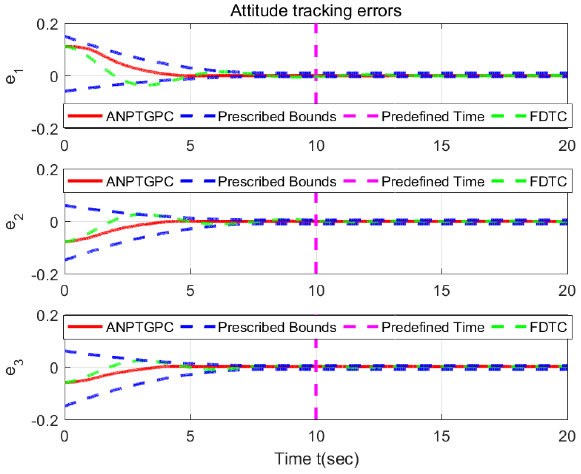
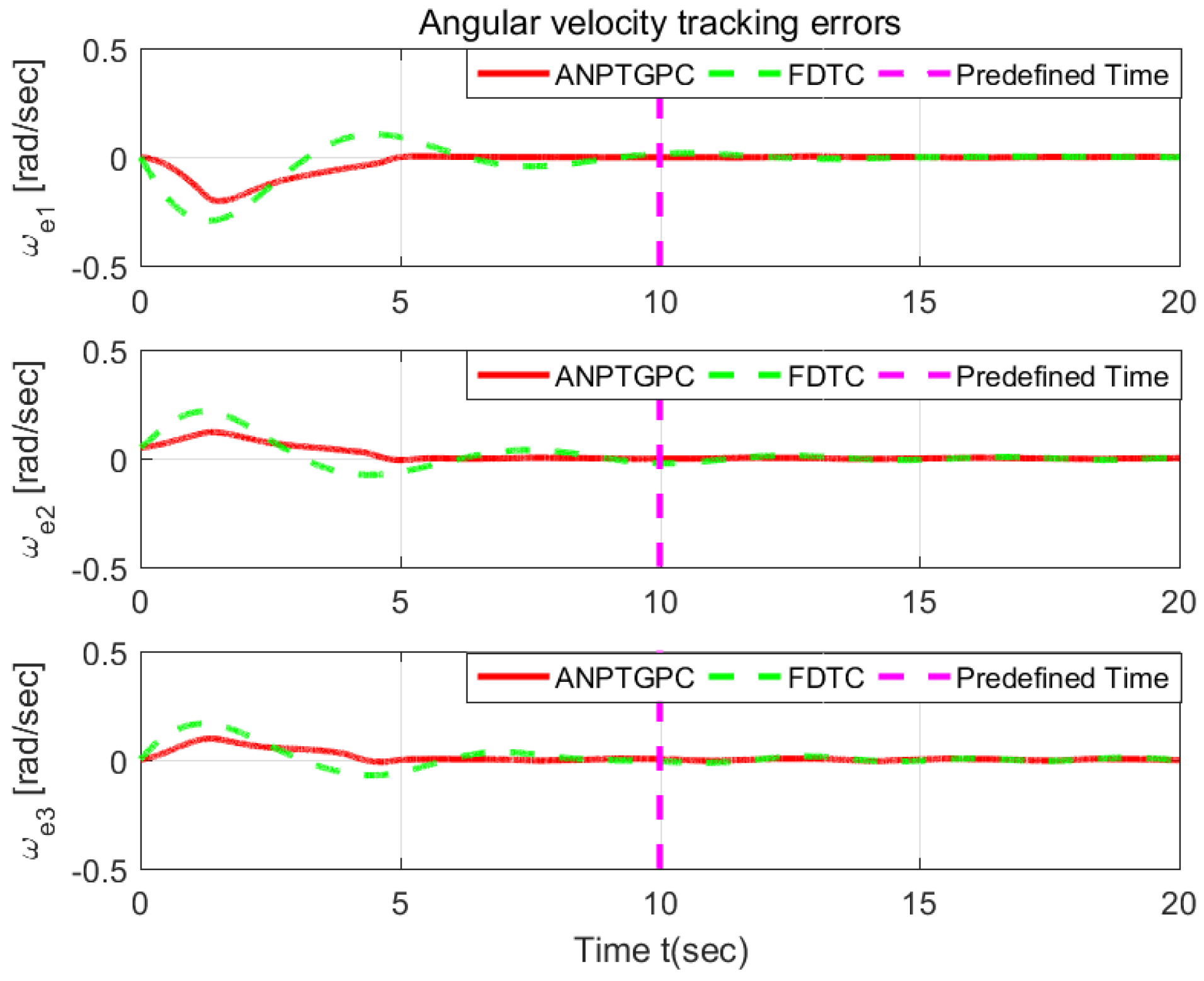
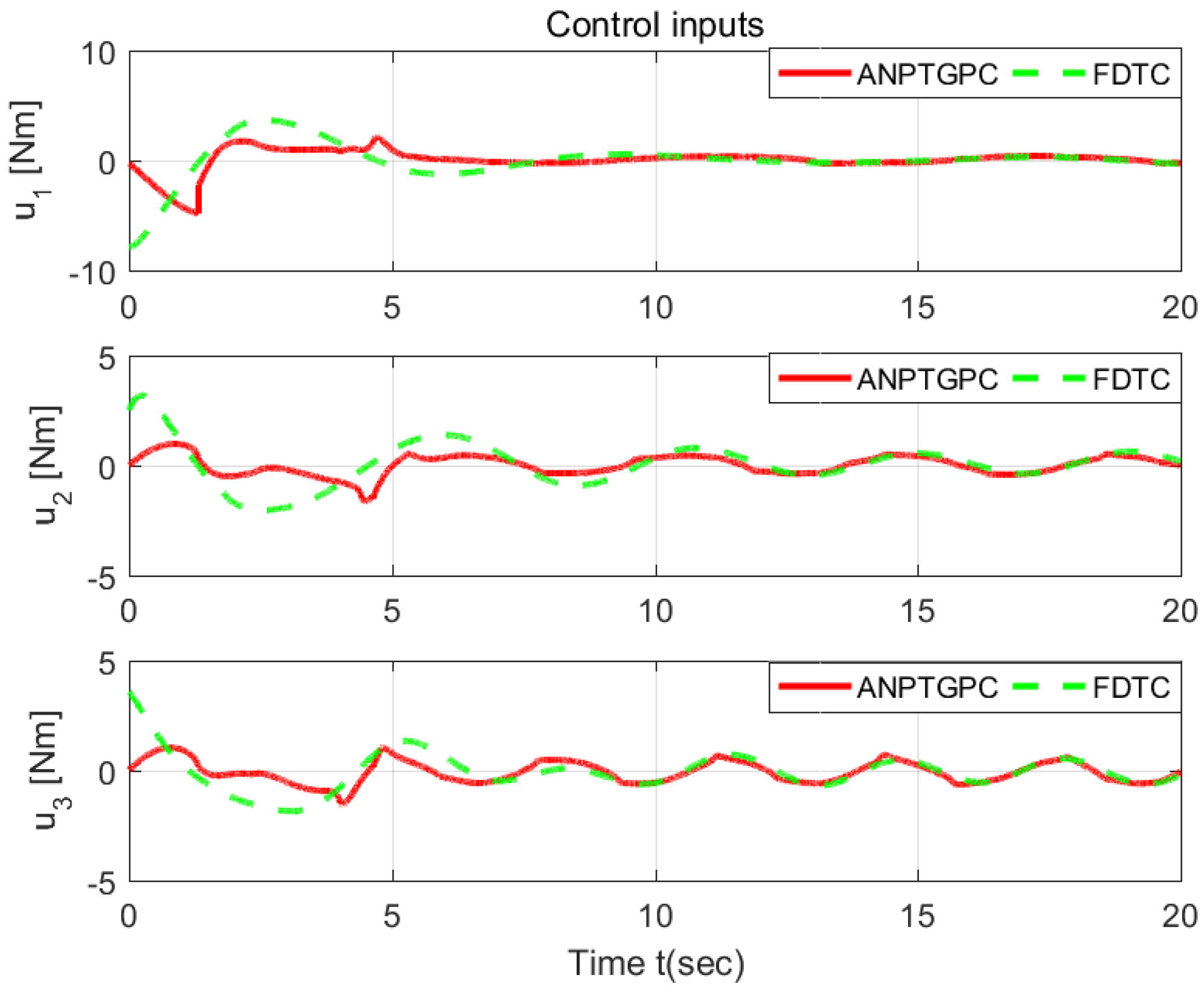
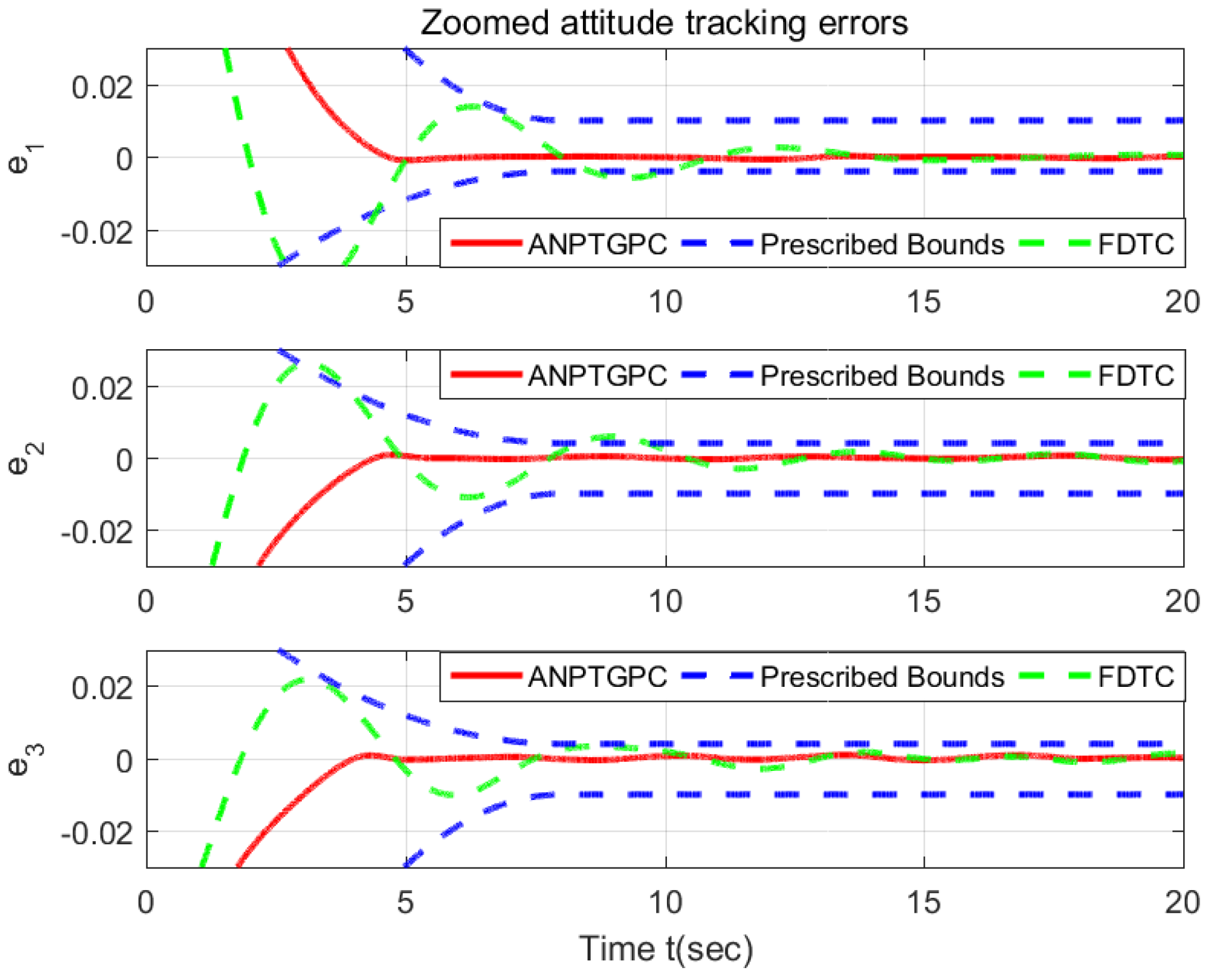
6.1. Validation the Proposed ANPTGPC

Firstly, the numerical simulation is demonstrated to verify the effectiveness of the proposed ANPTGPC. It is assumed that the spacecraft subject to the actuator partially loses its effort, and the actuator fault matrix is formulated as Γ = d i a g ( 0.95 + 0.03 sin ( 10 t ) , 0.85 + 0.02 sin ( 20 t ) , 0.75 + 0.01 sin ( 30 t ) ) and γ 0 = 0.74 . The parameters of the proposed ANPTGPC are selected as ρ 0 = 0.15 , ρ = 0.01 , λ = 2 , T c = 8 , μ = 0.3 , T 1 = 3 , T 2 = 3 , r 0 = 1.5 , δ = 0.1 , μ 1 = 0.8 , k = 15 , k 3 = 1 , k 4 = 0.1 , Λ = d i a g 1 , 1 , 1 , 1 , 1 , 1 , and δ 5 = 0.01 .
The simulation results performed on the actuator faulted spacecraft with ANPTGPC is illustrated in Figure 2, Figure 3 and Figure 4. It is clear that attitude tracking errors and angular velocity tracking errors remain the preseted region in predefined time. The proposed ANPTGPC obtains a favorable tracking performance for the spacecraft in the presence of partial loss of actuator effectiveness faults in Figure 2. It should be pointed out that the corresponding parameters of the prescribed performance function and predefined time function can be defined by the user a priori according to the requirement of engineering, and the result will change dynamically.
Secondly, the numerical simulation is illustrated to verify the predefined-time feature of the proposed controller that the convergence time can be defined by the user a priori and is independent on the initial conditions. This numerical simulation is accomplished with three different initial conditions (simpified as IC), q ( 0 ) = 0.11 , 0.08 , 0.06 T (IC1), q ( 0 ) = 1.11 , 1.08 , 1.06 T (IC2), and q ( 0 ) = 2.11 , 2.08 , 2.06 T (IC3).
The control parameters are the same as mentioned above. Clearly, the rapid convergence under three initial conditions can be assured, as we see in Figure 5 and Figure 6. The convergence time of the system with these three different initial conditions is almost the same, which shows an independence on the initial conditions.

6.2. Comparison with the FDTC

Comparison with the fixed-time attitude tracking control (FDTC) [10] is performed on the fault-free spacecraft to illustrate the effectiveness and improved performance of the proposed approach.
The FDTC of [10] is given by
u A = G T ( M 1 e ˙ + G T N + u n ) + u S + u M
u n = J ¯ 0 j = 1 2 l 1 j s i g ν j ( x j ) + j = 1 2 l 2 j s i g υ j ( x j )
u S = G T J ¯ 0 β 1 S p 3 p 3 q 3 q 3 + α 1 S γ 2 + κ s i g n ( S )
u M = G T ϑ ^ 2
where e is the attitude tracking error, and x 1 = e , x 2 = e ˙ , l 1 j , l 2 j , ν j > 1 , 0 < υ j < 1 , α 1 , β 1 and κ are positive constants. γ 2 = p 1 p 1 2 q 1 2 q 1 + m 1 m 1 2 n 1 2 n 1 + ( m 1 m 1 2 n 1 2 n 1 p 1 p 1 2 q 1 2 q 1 ) s i g n ( S 1 ) . These odd integrators p 3 , q 3 , p 1 , q 1 , m 1 , and n 1 are positive, S, M 1 , N, and J ¯ 0 are given as follows:
S = e ˙ t 0 t J ¯ 0 u n d r
M 1 = G T J 0 G T G ˙ + ( J 0 R ω d ) × G 1 + G T ( R ω d ) × J 0 + J 0 ( R ω d ) × ( J 0 G 1 e ˙ ) × G 1
N = ( R ω d ) × J 0 R ω d + J 0 R ω ˙ d
J ¯ 0 = G T J 0 G 1
and the output of the observer is ϑ ^ 2 given as follows:
ϑ ^ ˙ 1 = ι ϑ ^ 1 + ι ϑ ^ 2 ϑ sgn κ 2 ε 1
ϑ ^ ˙ 2 = κ 3 ε 1 κ 4 ϑ sgn p 0 p 0 q 0 q 0 κ 5 ϑ sgn γ 4 κ 6 s i g n ( ϑ sgn )
with ε 1 = ϑ ^ 1 ϑ 1 , ι , κ i , i = 2 6 are positive numbers. ϑ sgn = κ 1 s i g n ( ε 1 ) , ϑ sgn e = ϑ sgn ϑ sgn ι ι , γ 4 = p 0 p 0 2 q 0 2 q 0 + m 0 m 0 2 n 0 2 n 0 + ( m 0 m 0 2 n 0 2 n 0 p 0 p 0 2 q 0 2 q 0 ) s i g n ( ϑ sgn e 1 ) . p 0 , q 0 , m 0 , and n 0 are positive odd integrators.
The parameters of the FDTC are selected same as in [10] as: l 1 i = 0.3 , l 2 i = 0.6 , i = 1 , 2 , v 1 = 19 / 17 , v 2 = 19 / 18 , υ 1 = 17 / 19 , υ 2 = 17 / 18 , α 1 = β 1 = 1 , m 1 = 5 , n 1 = 3 , p 1 = 7 , q 1 = 9 , ι = 11 , m 3 = 11 , n 3 = 9 , p 3 = 9 , q 3 = 17 , κ = 0.02 , κ 1 = 0.17 , κ 2 = 0.074 , κ 3 = 0.056 , κ 4 = κ 5 = 0.1 , and κ 6 = 0.2 .
Due to the comparisons conducting on the fault-free spacecraft, the actuator fault matrix is chosen as Γ = d i a g ( 1.0 , 1.0 , 1.0 ) , and γ 0 = 1 . The other parameters are selected as ρ 0 = 0.15 , ρ = 0.01 , λ = 2 , T c = 10 , μ = 0.3 , T 1 = 3 , T 2 = 5 , r 0 = 1.5 , δ = 0.1 , μ 1 = 0.8 , k = 15 , k 3 = 1 , k 4 = 0.1 , Λ = d i a g 1 , 1 , 1 , 1 , 1 , 1 , and δ 5 = 0.01 .
As we see from the comparisons in Figure 7, Figure 8, Figure 9, Figure 10 and Figure 11, FDTC in [10] fails to constrain the attitude tracking error to the prescribed transient and steady-state error bounds, whereas the proposed ANPTGPC can achieve the guaranteed tracking performance. Furthermore, the developed approach is simple and obtains a fast transient in Figure 10 and Figure 11. It is worth pointing out that a quite favorable faster transient of the proposed ANPTGPC is achieved without an excessive control input over that of the DFTC in Figure 9.

7. Conclusions

This paper introduces a nonlinear prescribed performance function (NPPF), and a simple ANPTGPC based on NPPF and NPTSM is proposed to address the predefined-time attitude tracking for rigid spacecraft with model uncertainties, bounded external disturbances, and actuator faults. Lyapunov stability theory is used to prove the predefined time stability of closed-loop systems with guaranteed performance. The appealing features of the proposed ANPTGPC include the absence of a model, fault-tolerance, non-singularity, and predefined-time stability with guaranteed performance. Numerical simulations and comparisons are illustrated to validate the effectiveness and improved performance of the proposed control. However, we can only obtain approximate predefined time stability instead of the strict predefined time stability. Our future work can address this weakness.

Author Contributions

Conceptualization, L.H. and Z.W.; methodology, Z.W.; software, C.C.; validation, H.Y., Z.W. and C.C.; formal analysis, Z.W.; investigation, L.H.; resources, L.H.; data curation, L.H.; writing—original draft preparation, Z.W.; writing—review and editing, Z.W.; visualization, C.C.; supervision, L.H.; project administration, Z.W.; funding acquisition, Z.W. All authors have read and agreed to the published version of the manuscript.

Funding

This work was supported by the Education Department of Shaanxi Province with Grant/Award Numbers 21JK0675 and the Natural Science Foundation of Shaanxi Province with Grant/Award Numbers 2023-JC-QN-0738.

Data Availability Statement

The data that support the findings of this study are available from the corresponding author upon reasonable request.

Acknowledgments

The authors would like to thank the anonymous reviewers, Associate Editor, and Editor for their valuable comments, which were helpful in improving the quality of this article.

Conflicts of Interest

The authors declare no conflicts of interest.

Appendix A. Proof of Proposition 1

Proof. 
Once the sliding surface S = 0 is achieved, from (40), we have
ε 2 = π λ m A μ T 1 α s i g 1 + μ ( ε 1 ) + β f ( ε 1 )
For system (A1), the following positive-definite Lyapunov function candidate is selected:
V 1 = 1 2 ε 1 T ε 1
Taking the derivative of V 1 with respect to time along (A1), we obtain
V ˙ 1 = ε 1 T ε ˙ 1 = ε 1 T A ε 2
(i)
For the case ε 1 i > δ
Using the definitions of (A1), (39), and (41), (A3) can be rewritten as
V ˙ 1 π λ m A λ m A μ T 1 α i = 1 3 ε 1 i 2 + μ + β i = 1 3 ε 1 i 2 μ
Recalling the definitions of α and β in (40), (A4) can be explicitly expressed as
V ˙ 1 π μ T 1 2 1 + μ 2 3 μ 2 i = 1 3 ε 1 i 2 + μ + 2 1 μ 2 i = 1 3 ε 1 i 2 μ
Applying Lemma 3 yields
V ˙ 1 π μ T 1 ε 1 2 1 + μ 2 + ε 1 2 1 μ 2
In light of (A2), it is obvious that (A6) is given by
V ˙ 1 π μ T 1 V 1 1 + μ 2 + V 1 1 μ 2
It is clear that, by invoking Lemma 1, ε 1 i converges to a small region in predefined time T 1 .
(ii)
For the case ε 1 i δ
By virture of the definition of (41), we have
V ˙ 1 = ε 1 T A π λ m A μ T 1 α s i g 1 + μ ( ε 1 ) + β f ( ε 1 ) π λ m A μ T 1 α i r 0 1 + μ r 0 1 δ μ i = 1 3 ε 1 i 2 π λ m A μ T 1 α i μ 1 r 0 δ 1 μ r 0 i = 1 3 ε 1 i 1 + r 0
Utilizing the fact δ 1 r 0 ε 1 i 1 r 0 for the selection of 1 < r 0 2 , we obtain
V ˙ 1 π λ m A μ T 1 δ μ i = 1 3 α i ε 1 i 2 0
Clearly, we have V ˙ 1 0 from (A9). Furthermore, V ˙ 1 = 0 means that ε 1 = 0 . Thus, utilizing the LaSalle’s invariance theorem [35], we can conclude that the transformed error ε 1 i will converge to zero asymptotically. In light of (23), we can obtain that the attitude tracking error will go to a small region in predefined time, and then converge to zero asymptotically. □

Appendix B. Proof of Theorem 1

Proof. 
We select the positive definite-Lyapunov function candidate as follows:
V 2 = 1 2 S T M q S + 1 2 θ ˜ T Λ 1 θ ˜ + 1 2 ϑ ˜ k 1 ϑ ˜
After taking the time derivative of Equation (A10), we have
V ˙ 2 = 1 2 S T M ˙ q S + S T M q S ˙ + θ ˜ T Λ 1 θ ˜ ˙ + ϑ ˜ k 1 ϑ ˜ ˙
If (60) and (53) are substituted into (A11), and Property 2, Assumption 1, and P T 4 are utilized, then
V ˙ 2 S T φ q , q d , q ˙ , q ˙ d , q ¨ d θ ˜ + 4 S ϑ ˜ θ ˜ T Λ 1 θ ^ ˙ ϑ ˜ ϑ ^ ˙ k + S T P T u 1 P T ( I 3 Γ ) u 0 + u 1 + P T Γ u 2
Using (54) and (55) and the facts that I 3 Γ = λ M ( I 3 Γ ) 1 γ 0 and γ 0 λ m ( Γ ) , we obtain
V ˙ 2 S T φ q , q d , q ˙ , q ˙ d , q ¨ d θ ˜ + 4 S ϑ ˜ θ ˜ T Λ 1 θ ^ ˙ ϑ ˜ ϑ ^ ˙ k S T k 0 S + P S 1 γ 0 u 0 + u 1 1 γ 0 u 0 + u 1 P S
Substituting (56) and (57) into (A13), and applying the facts that θ ˜ i θ ^ i = θ ˜ i θ i θ ˜ i θ ˜ i 2 2 + θ i 2 2 and ϑ ˜ ϑ ^ ϑ ˜ 2 2 + ϑ 2 2 yields
V ˙ 2 i = 1 6 Λ i i 1 k 3 θ ˜ i 2 2 θ i 2 2 k 4 k ϑ ˜ 2 2 ϑ 2 2 S T k 0 S = S T k 0 S 1 2 k 3 θ ˜ T Λ 1 θ ˜ 1 2 k 4 ϑ ˜ k 1 ϑ ˜ + 1 2 k 3 θ T Λ 1 θ + 1 2 k 4 ϑ k 1 ϑ
By utilizing the fact that S T k 0 S k 0 8 J M 1 2 S T M q S , we have
V ˙ 2 ι V 2 + δ 1
ι = min k 0 8 J M , 1 , δ 1 = 1 2 k 3 θ T Λ 1 θ + 1 2 k 4 ϑ k 1 ϑ
Clearly, using Theorem 4.18 in [36], we obtain that S, θ ˜ and ϑ ˜ are UUB. Furthermore, based on the definitions in (40), (32), (23), and (19), ε 1 , ε 2 , e, e ˙ , q, and q ˙ are also UUB.
Hence, this term S T φ θ ˜ + 4 S ϑ ˜ is bounded and is assumed as
S T φ q , q d , q ˙ , q ˙ d , q ¨ d θ ˜ + 4 S ϑ ˜ δ 2
where δ 2 is a positive constant. □

Appendix C. Proof of Theorem 2

Proof. 
We propose the positive definite-Lyapunov function candidate as follows:
V 3 = 1 2 S T M q S
Differentiating V 3 with respect to time, it can be concluded that
V ˙ 3 = 1 2 S T M ˙ q S + S T M q S ˙
Substituting M ( q ) S ˙ from (62) into (A19), and utilizing property 2, assumption 1, P T 4 , it can be concluded that
V ˙ 3 S T φ q , q d , q ˙ , q ˙ d , q ¨ d θ ˜ + 4 S ϑ ˜ + π S T k 1 s i g 1 + μ 1 S + k 2 s i g 1 μ 1 S μ 1 T 2 + S T P T ( I 3 Γ ) u 0 + u 1 + P T Γ u 2
Similar to (A13), after substituting u 2 from (55) into (A20), and utilizing (A17), we obtain
V ˙ 3 π S T k 1 s i g 1 + μ 1 S + k 2 s i g 1 μ 1 S μ 1 T 2 + δ 2
By utilizing the definition of k i , i = 1 , 2 and the fact that V 3 8 J M S 2 = 8 J M S T S , as well as Lemmas 3 and 4, we have
V ˙ 3 σ π μ 1 T 2 V 3 1 + μ 1 2 + V 3 1 μ 1 2 + δ 2
where σ = min 1 8 J M 1 + μ 1 2 , 1 8 J M 1 μ 1 2 . From Theorem 1, it is clear that S is UUB, which means that V 3 is bounded, and π μ 1 T 2 V 3 1 + μ 1 2 + V 3 1 μ 1 2 δ 3 with the positive constant δ 3 . Hence, (A22) can be rewritten as
V ˙ 3 π μ 1 T 2 V 3 1 + μ 1 2 + V 3 1 μ 1 2 + δ 4
with the positive constant δ 4 = max δ 2 , δ 2 + σ 1 δ 3 .
According to Lemma 2, it is clear that S converges to a small region in predefined time from (A23). In light of Proposition 1, we can obtain that attitude tracking error will go to a small region in predefined time, and then converge to zero asymptotically. □

References

  1. Bhat, S.P.; Bernstein, D.S. Finite-time stability of continuous autonomous systems. SIAM J. Control Optimiz. 2000, 38, 751–766. [Google Scholar] [CrossRef]
  2. Du, H.; Li, S.; Qian, C. Finite-time attitude tracking control of spacecraft with application to attitude synchronization. IEEE Trans. Autom. Control 2011, 56, 2711–2717. [Google Scholar] [CrossRef]
  3. Lu, K.; Xia, Y. Adaptive attitude tracking control for rigid spacecraft with finite-time convergence. Automatica 2013, 49, 3591–3599. [Google Scholar] [CrossRef]
  4. Zou, A. Finite-time output feedback attitude tracking control for rigid spacecraft. IEEE Trans. Control Syst. Technol. 2014, 22, 338–345. [Google Scholar] [CrossRef]
  5. Wang, Z.; Su, Y.; Zhang, L. A new nonsingular terminal sliding mode control for rigid spacecraft attitude tracking. J. Dyn. Sys. Meas. Control 2018, 140, 051006. [Google Scholar] [CrossRef]
  6. Polyakov, A. Nonlinear feedback design for fixed-time stabilization of linear control systems. IEEE Trans. Autom. Control 2012, 57, 2106–2110. [Google Scholar] [CrossRef]
  7. Jiang, B.; Hu, Q.; Friswell, M.I. Fixed-time attitude control for rigid spacecraft with actuator saturation and faults. IEEE Trans. Control Syst. Technol. 2016, 24, 1892–1898. [Google Scholar] [CrossRef]
  8. Esmailzadeh, S.M.; Golestani, M. Comment on fixed-time attitude control for rigid spacecraft with actuator saturation and faults. IEEE Trans. Control Syst. Technol. 2018, 27, 1846. [Google Scholar] [CrossRef]
  9. Chen, Q.; Xie, S.; Sun, M.; Xie, S.; He, S. Adaptive nonsingular fixed-time attitude stabilization of uncertain spacecraft. IEEE Trans. Aerosp. Electron. Syst. 2018, 54, 2937–2950. [Google Scholar] [CrossRef]
  10. Gao, J.; Fu, J.; Zhang, S. Adaptive fixed-time attitude tracking control for rigid spacecraft with actuator faults. IEEE Trans. Ind. Electron. 2019, 66, 7141–7149. [Google Scholar] [CrossRef]
  11. Wang, Z.; Su, Y.; Zhang, L. Fixed-time fault-tolerant attitude tracking control for rigid spacecraft. J. Dyn. Sys. Meas. Control 2020, 142, 024502. [Google Scholar] [CrossRef]
  12. Sun, H.; Hou, L.; Zong, G.; Yu, X. Fixed-time attitude tracking control for spacecraft with input quantization. IEEE Trans. Aerosp. Electron. Syst. 2018, 55, 124–134. [Google Scholar] [CrossRef]
  13. Wang, Z.; Su, Y.; Zhang, L. Fixed-time attitude tracking control for rigid spacecraft. IET Control Theory Appl. 2020, 14, 790–799. [Google Scholar] [CrossRef]
  14. Sanchez-Torres, J.; Sanchez Edgar, N.; Loukianov Alexander, G. Predefined-time stability of dynamical systems with sliding modes. In Proceedings of the 2015 American Control Conference, Chicago, IL, USA, 1–3 July 2015; pp. 5842–5846. [Google Scholar]
  15. Jimenez-Rodriguez, E.; Munoz-Vazquez, A.; Sanchez-Torres, J.; Defoort, M.; Loukianov Alexander, G. A Lyapunov-like characterization of predefined-time stability. IEEE Trans. Autom. Control 2020, 65, 4922–4927. [Google Scholar] [CrossRef]
  16. Wang, F.; Miao, Y.; Li, S.C.; Hwang, I. Attitude control of rigid spacecraft with predefined-time stability. J. Frankl. Inst. 2020, 4212–4221. [Google Scholar] [CrossRef]
  17. Xie, S.; Chen, Q. Adaptive nonsingular predefined-time control for attitude stabilization of rigid spacecrafts. IEEE Trans. Circuits Syst. II-Express Briefs 2022, 69, 189–193. [Google Scholar] [CrossRef]
  18. Xie, S.; Chen, Q.; He, X. Predefined-time approximation-free attitude constraint control of rigid spacecraft. IEEE Trans. Aerosp. Electron. Syst. 2023, 59, 347–358. [Google Scholar] [CrossRef]
  19. Ye, D.; Zou, A.; Sun, Z. Predefined-time predefined-bounded attitude tracking control for rigid spacecraft. IEEE Trans. Aerosp. Electron. Syst. 2022, 58, 464–472. [Google Scholar] [CrossRef]
  20. Wang, W.; Hou, M.; Fu, Y.; Liu, B. Continuous precise predefined-time attitude tracking control for a rigid spacecraft. Int. J. Control 2023, 96, 922–934. [Google Scholar] [CrossRef]
  21. Bechlioulis, C.; Rovithakis, G. Prescribed performance adaptive control for multi-input multi-output affine in the control nonlinear systems. IEEE Trans. Autom. Control 2010, 55, 1220–1226. [Google Scholar] [CrossRef]
  22. Bechliouliss, C.; Rovithakis, G. Robust adaptive control of feedback linearizable MIMO nonlinear systems with prescribed performance. IEEE Trans. Autom. Control 2008, 53, 2090–2099. [Google Scholar] [CrossRef]
  23. Yin, Z.; Suleman, A.; Luo, J.; Wei, C. Appointed-time prescribed performance attitude tracking control via double performance functions. Aerosp. Sci. Technol. 2019, 93, 105337. [Google Scholar] [CrossRef]
  24. Liu, M.; Shao, X.; Ma, G. Appointed-time fault-tolerant attitude tracking control of spacecraft with double-level guaranteed performance bounds. Aerosp. Sci. Technol 2019, 92, 337–346. [Google Scholar] [CrossRef]
  25. Gao, S.; Liu, X.; Jing, Y.; Dimirovski, G. Finite-Time Prescribed Performance Control for Spacecraft Attitude Tracking. IEEE/ASME Trans. Mechatron. 2022, 27, 3087–3098. [Google Scholar] [CrossRef]
  26. Wang, Z.; Ma, J.; Wang, C. Predefined-time guaranteed performance attitude tracking control for uncertain rigid spacecraft. IET Control Theory Appl. 2022, 16, 1807–1819. [Google Scholar] [CrossRef]
  27. Hasan, M.; Haris, M.; Qin, S. Fault-tolerant spacecraft attitude control: A critical assessment. Prog. Aerosp. Sci. 2022, 130, 100806. [Google Scholar] [CrossRef]
  28. Yu, S.; Yu, X.; Shirinzadeh, B.; Man, Z. Continuous finite-time control for robotic manipulators with terminal sliding mode. Automatica 2005, 41, 1957–1964. [Google Scholar] [CrossRef]
  29. Zuo, Z.; Tie, L. SDistributed Robust finite-time nonlinear consensus protocols for multi-gent systems. Int. J. Syst. Sci. 2016, 47, 1366–1375. [Google Scholar] [CrossRef]
  30. Sanyal, A.; Fosbury, A.; Chaturvedi, N.; Bernstein, D. Inertia-free spacecraft attitude tracking with disturbance rejection and almost global stabilization. AIAA J. Guid. Control Dyna 2009, 32, 1167–1178. [Google Scholar] [CrossRef]
  31. Wong, H.; de Queiroz, M.S.; Kapila, V. Adaptive tracking control using Synthesized velocity from attitude measurements. Automatica 2001, 37, 947–953. [Google Scholar] [CrossRef]
  32. Cai, W.; Liao, X.; Song, Y. Indirect robust adaptive fault-tolerant control for attitude tracking of spacecraft. AIAA J. Guid. Control Dyna 2008, 31, 1456–1463. [Google Scholar] [CrossRef]
  33. Bustan, D.; Sani, S.; Pariz, N. Adaptive fault-tolerant spacecraft attitude control design with transient response control. IEEE/ASME Trans. Mechatron. 2013, 19, 1404–1411. [Google Scholar]
  34. Tsiotras, P. Further passivity results for the attitude control problem. IEEE Trans. Autom. Control 1998, 43, 1597–1600. [Google Scholar] [CrossRef]
  35. Slotine, J.J.E.; Li, W. Applied Nonlinear Control; Prentice Hall: Englewood Cliffs, NJ, USA, 1991. [Google Scholar]
  36. Khalil, H. Nonlinear Systems; Prentice Hall: Englewood Cliffs, NJ, USA, 2002. [Google Scholar]
Figure 1. NPPF with different predefined time T c .
Mathematics 13 00832 g001
Figure 2. Attitude tracking errors.
Mathematics 13 00832 g002
Figure 3. Angular velocity tracking errors.
Mathematics 13 00832 g003
Figure 4. Control inputs.
Mathematics 13 00832 g004
Figure 5. Attitude tracking errors with different IC.
Mathematics 13 00832 g005
Figure 6. Angular velocity tracking errors with different IC.
Mathematics 13 00832 g006
Figure 7. Comparison of attitude tracking errors.
Mathematics 13 00832 g007
Figure 8. Comparison of angular velocity tracking errors.
Mathematics 13 00832 g008
Figure 9. Comparison of control inputs.
Mathematics 13 00832 g009
Figure 10. Comparison of zoomed attitude tracking errors.
Mathematics 13 00832 g010
Figure 11. Comparison of zoomed angular velocity tracking errors.
Mathematics 13 00832 g011
Disclaimer/Publisher’s Note: The statements, opinions and data contained in all publications are solely those of the individual author(s) and contributor(s) and not of MDPI and/or the editor(s). MDPI and/or the editor(s) disclaim responsibility for any injury to people or property resulting from any ideas, methods, instructions or products referred to in the content.

