Abstract
Unmanned aerial vehicles (UAVs) are a promising technology for future sixth-generation (6G) wireless networks. They are airborne vehicles that act either as as flying relays or base stations (BS) to provide the line-of-sight (LOS) transmission, enable wide-area coverage, and increase the spectral efficiency. In this work, a UAV is employed to forward information from the BS to distant users using a decode-and-forward (DF) protocol. The BS serves ground users through UAV by employing non-orthogonal multiple access (NOMA). The UAV relay will be wirelessly powered and harvests energy from the BS by applying a simultaneous wireless information and power transfer (SWIPT) technique. To further improve overall performance, the near user will act as a full-duplex (FD) relay to forward the far user’s information by applying cooperative non-orthogonal multiple access (C-NOMA). The proposed scheme considers a practical detection order using a feasible successive interference cancellation (SIC) operation. Additionally, a relay power control method is introduced for the near user to guarantee a reliable cooperative link. In the proposed scheme, a low-complexity closed-form power allocation is derived to maximize the minimum achievable rate. Numerical results demonstrate that the power allocation scheme significantly improves the far user’s rate performance, and the proposed scheme guarantees a higher target rate and outperforms the conventional NOMA, half-duplex (HD) C-NOMA, and FD C-NOMA with fixed power allocation (FPA) and fractional transmit power allocation (FTPA) schemes.
Keywords:
unmanned aerial vehicle (UAV); cooperative communication; non-orthogonal multiple access (NOMA); full-duplex (FD); SWIPT; maximal ratio combining (MRC); power allocation MSC:
94A05; 90B18; 90-10
1. Introduction
Next-generation wireless technology, including the sixth generation (6G), will encounter tremendous mobile data traffic and remarkably improve the quality of service (QoS) such as data rate, latency, and wide-communication coverage [1]. One of the main goals of future generation is to maximize the coverage and connect the unconnected in rural and natural disaster situation areas by merging the air, ground, and space networks [2]. Non-terrestrial network (NTN) systems are a promising innovation for 6G future wireless networks, offering an effective solution to provide services in unconnected areas [3]. Unmanned aerial vehicles (UAVs) are expected to be potential means for future wireless networks and are capable to enable transmission to out-of-range ground users in ultra-dense, rural, or natural disaster-affected areas [2,4]. With the high demand for mobile data traffic, non-orthogonal multiple access (NOMA), simultaneous wireless information and power transfer (SWIPT), and cooperative communication are potential technologies expected to meet these requirements. Next-generation multiple access (NGMA) techniques have been widely investigated as an essential enabler for accommodation a large number of connected devices while enhancing the spectral efficiency [5]. NOMA is emerging as a strong contender for NGMA, and an advanced scheme that can enhance the data rate, reduce latency and enables multiple users to share the same spectrum efficiently [6,7].
1.1. Related Work
Research on downlink (DL) NOMA with UAVs, SWIPT, and cooperative communication has been widely investigated. NOMA has been extensively explored in the literature due to its ability to deliver superior performance compared to existing multiple access schemes. One of the distinguishing features of NOMA is its capability to leverage the near user’s awareness of other users’ information, enabling integration with cooperative communication techniques [8]. Cooperative NOMA (C-NOMA) can enhance spatial diversity to improve the far user’s rate and expand cell coverage. In C-NOMA, the near user with better channel gains acts as a relay to transmit the far user’s signal, thereby enhancing the reception reliability of the far user, as it receives its information from the near user and the base station (BS) [9]. Research on C-NOMA initially focused on half-duplex (HD) mode [10], and the result demonstrated that the outage probability performance can attain the maximum achievable diversity gains. In [11], a C-NOMA system with SWIPT was studied, where the near user harvested energy to forward the information to the far user. Nevertheless, the near user’s rate was significantly decreased due to the additional timeslot required for HD mode.
Full-duplex (FD) technique is a promising solution to address the additional timeslot problem, as it allows the near user to transmit and receive simultaneously, effectively doubling spectral efficiency [12]. In [12], outage performance of Full-duplex (FD) C-NOMA system was investigated, where two users were paired using device-to-device (D2D) cooperation. In [13], the performance of the total sum rate in the FD C-NOMA system, incorporating energy harvesting and beamforming, was maximized. The maximization of the minimum achievable rate is formulated in [14] for two NOMA users, with the strong user functioning as a HD/FD relay. In [15], a practical performance analysis of the FD C-NOMA system was examined, focusing on maximizing minimum achievable rate. In [16], the outage performance of cooperative relaying-based NOMA with SWIPT was analyzed, addressing two scenarios where the direct link between the BS and the far user did not exist and another where it was present. In [17], a user pairing and power control scheme for hybrid HD/FD C-NOMA was derived, in which the near user assisted the transmission between the BS and the far user. Additionally, the outage and throughput analysis of the FD C-NOMA system using imperfect successive interference cancellation (SIC) was studied in [18], where the BS communicated with the far user through a dedicated relay.
Recently, UAVs became a key technology to support next-generation cellular networks. Due to their higher placement, UAVs can be utilized to enable an air-to-ground transmission for ground users by performing as a BS or flying relay [19,20]. Consequently, the wireless connectivity and the channel of the far user will be improved. The integration of NOMA with UAVs was explored in [21], where the ergodic capacity and outage probability performance of a UAV-assisted NOMA system were analyzed. In [22], UAV-enabled C-NOMA with hardware impairments was investigated, and the optimal power and time allocation were derived. Moreover, the sum rate maximization of a fixed altitude UAV-assisted C-NOMA system using harvested energy was studied in [23]. In [24], hybrid HD/FD UAV-relay assisted ground NOMA user were studied, and the sum rate maximization of the system was formulated. In [25], a deep deterministic policy gradient (DDPG) framework was introduced to optimize mobility management, reduce handover failures, and mitigate path loss in UAV-RIS-assisted networks. The framework jointly optimizes UAV trajectories and RIS phase shifts to improve throughput, energy efficiency, and line-of-sight probability, while effectively reducing outage probability and handover failure rates. A secure multiple UAV-assisted multi-user multiple-input multiple-output (MU-MIMO) system was investigated in [26] to reduce power consumption and improve secrecy. The proposed scheme optimized power allocation, precoding, and UAV trajectory using a recurrent convolutional neural network (RCNN) and deep unfolding. In [27], the outage probability of a UAV-aided agricultural Internet of Things (Agri-IoT) network using SWIPT and multiple-input single-output (MISO)-NOMA was examined. The proposed scheme used a transmit antenna selection (TAS) technique to optimize the outage probability performance under imprecise channel state information (CSI). The outage probability and intercept probability performances for a UAV-assisted system with two users using NOMA were analyzed in [28]. Moreover, a proposed artificial noise scheme was investigated, which helps to increase the physical-layer security of the near user. In [29], a hybrid transmission technique is studied to enhance reliability in Ultra-Reliable and Low-Latency Communication (URLLC). The proposed hybrid scheme dynamically switches between Terahertz link and millimetre wave (mmWave) link, and it achieves high reliability and making it as an efficient solution for future networks.
In existing works, the signal from the source, which is in this case UAV, and the near user are mostly assumed to be fully resolvable at the far user; hence, the two signal-to-noise ratios (SNRs) can be added directly by applying maximal ratio combining (MRC) [12,13,14]. However, the analysis in those papers is not practical as they assume the two signals will cause no interference to each other [30,31]. This assumption is particularly challenging as the successive interference cancellation (SIC) operation demands that the UAV’s NOMA superposed signal for the near and far users to be considerably weaker or stronger than the relayed far user’s signal. Even when this condition is satisfied, the far user signal will receive its information from the UAV node and the near user with all interference when the SIC process is firstly applied. Therefore, a more practical FD C-NOMA approach with a feasible SIC process is required.
1.2. Motivation and Contributions
A UAV-assisted FD C-NOMA with the use of SWIPT is presented in this paper. The wireless powered UAV is flying in a fixed altitude to receive the NOMA signal from the BS and forward it to the distant users. The UAV employs SWIPT to meet the high demand of transmission power. In this work and unlike [12,13,14], the far user utilizes a feasible SIC process to decode its own signal from the UAV and near user. After performing SIC, the far user applies MRC to merge the two SNRs. This method firstly allows the far user to extract its own signal from the UAV, including all interference components from both the UAV and the near user. The far user then identifies the near user’s signal within the UAV NOMA superposed signal and cancels it using SIC. Subsequently, the far user can obtain the relayed signal from the near user with no interference, which then can be combined with the signal from the UAV by MRC. Furthermore, the capacity equations of the proposed system are formulated, and a power control mechanism is implemented to maintain an efficient cooperative link to the far user while reducing the impact of self-interference (SI). To this end, the major contributions of this paper can be summarized as follows:
- A feasible detection order for practical SIC implementation is employed by the far user to decode its signal received from the UAV and the near user.
- The capacity equations for the proposed UAV-assisted FD C-NOMA system with a practical SIC operation model are derived. Additionally, a power control mechanism is implemented introduced to ensure a reliable cooperative link for the far user while mitigating SI effects. It guarantees that the signal-to-interference-plus-noise ratio (SINR) of the cooperative link does not exceed the SINR at the near user when detecting the far user’s information.
- Combining the proposed scheme with power splitting SWIPT for the UAV to simultaneously receive information and harvest energy for cooperative transmission is investigated.
- Finally, a low-complexity closed-form solution is derived to maximize the minimum achievable rate (Max–Min) for the proposed scheme. The power allocation problem is reformulated into a quasi-concave form, which is subsequently converted into multiple sets of convex problems to find the optimal solution. Moreover, the optimization problem is solved using a power control approach with the objective of maximizing the minimum achievable rate.
1.3. Paper Organization
The rest of this paper is organized as follows: Section 2 describes the system model used in this study. Section 3 presents the performance analysis of the proposed UAV-assisted FD C-NOMA system. In Section 4, the power control scheme for the near user’s transmission power is illustrated. Section 5 describes the formulation of the closed-form power allocation schemes. In Section 6, numerical simulation results to evaluate the system’s performance are presented. Lastly, Section 7 concludes the paper.
2. System Model and Assumptions
A UAV-aided full-duplex cooperative NOMA communication system is considered, in which the wirelessly powered UAV is deployed to enable the communication between the terrestrial BS and two NOMA users located outside the coverage area, as shown in Figure 1. The wirelessly powered UAV flies at a fixed altitude and employs SWIPT to meet the high transmission power demands. The UAV acts as a decode-and-forward (DF) relay when the BS is unable to transmit the superposed signals to two NOMA users beyond its coverage area due to factors such as long distances, large obstacles, or emergency scenarios like natural disasters. In addition, the UAV harvests energy form the BS and is equipped with a single antenna. Furthermore, it assists two distant users through power-domain NOMA and operates in HD modes, with the entire transmission process occurred in two timeslots. The near user contains a single transmit antenna and a single receive antenna and applies FD protocol. It is also capable of temporarily storing the far user signal and forward it to the far user . Subsequently, receives two copies of its own information from the UAV and . It is important to mention that SI arises in the FD C-NOMA mode. The CSI is assumed to be perfectly known at the BS, but in practice channel estimation is needed. In practice, CSI is estimated through pilot signals, which might cause errors or feedback delay. Imperfect or outdated CSI leads to mismatches between the actual and estimated channel gains. As a result, the accuracy of power allocation and the achievable SINR will be degraded.
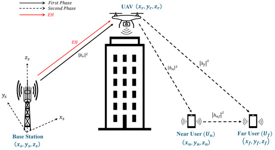
Figure 1.
System Model of the proposed UAV-assisted FD C-NOMA Scheme.
All terminals are considered a three-dimensional (3D) Cartesian coordinates. The BS and UAV are located at different coordinates known as and , respectively. Moreover, the far user is positioned as and the near user has location coordinates identified by . The distance between the BS and UAV is denoted as , and the distance between the UAV and user i is denoted as , where , and is the distance between and . According to the 3GPP report, the line-of-sight (LoS) possibility between the UAV and the BS, as well as ground users, approaches nearly 100% when the UAV’s height is around 100 m in the urban macro-cellular scenario and above 40 m in the rural area [32,33]. Therefore, the three channels consist of the connection between the BS and the UAV relay, as well as the channels between the UAV relay and the two NOMA users are assumed to experience independent and identically distributed (i.i.d) Rician fading. The channel coefficients for those links are given as , , where is the free space pathloss, is modelled as Rician fading, represents the log-normal shadowing, and i illustrate the connections between the terminals, in which link r is the connection between the BS and the UAV, link f refers to the connection between the UAV and the far user , and link n is the connection between the UAV and the near user . The channel gains are considered to be in ascending order as . In this work, the link between the two NOMA users is assumed to behave as a non-LoS (NLoS), and hence, the channel gain is represented as , where is the effect of Rayleigh fading and is the log-normal shadowing. In addition, all channels are slowly varying over the two timeslots and remain the same. The following assumptions define the system model.
Assumption 1.
The BS communicates with two static NOMA users and located at fixed coordinates via wirelessly powered UAV at a fixed altitude. The considered propagation environment can be applied to rural, emergency, or suburban scenarios, where direct communication between the BS and users is limited due to long distances or weak coverage.
Assumption 2.
The UAV operates in HD mode, and the near user applies FD protocol with residual SI effect and simultaneously receives and forwards the far user signal.
Assumption 3.
All links experience flat fading; BS-UAV and UAV-ground users links follow Rician fading, while - follows Rayleigh fading.
Assumption 4.
CSI is assumed to be perfectly known at the BS.
Assumption 5.
The channel gains are considered to be in ascending order as .
Assumption 6.
The UAV employs SWIPT with power-splitting factor ρ.
Assumption 7.
The SIC is assumed to be perfect.
3. Performance Analysis
In this section, the capacity equation of the near and far users are derived. In addition, the rate expressions of UAV-assisted FD C-NOMA and the power control of the cooperative transmission by the near user are formulated.
3.1. Phase 1: Direct Transmission (From the BS to the UAV)
In this work, a power allocation is used in which , where and are the power allocation for the far and near users, respectively. It should be noted and . In the first phase the BS transmits a superposed signal simultaneously to the UAV. The received observation at the UAV can be written as
where is the information symbol for user i, is the total BS transmission power, and is the additive white Gaussian noise (AWGN) with power spectral density . In order to avoid the UAV draining its own battery while assisting both NOMA users, SWIPT is employed for the UAV to receive its information and harvest energy simultaneously. With power splitting technique, the received power by the UAV is split by a power-splitting factor for energy harvesting and information decoding. Consequently, the received observation at the UAV after using SWIPT can be given as
ranges between 0 and 1. A value of implies that the entire received power is used for energy harvesting, whereas indicates that all the power is utilized for information decoding. The resulting signal-to-interference-plus-noise ratio (SINR) at the UAV for detecting the far user’s signal after applying SWIPT is given
The detected signal is then removed from the received signal by SIC, and hence, the signal-to-noise ratio (SNR) at the UAV for detecting the near user’s signal with SWIPT can be expressed as
The power-splitting receiver at the UAV is assumed to harvest only the signal power, while the noise power is considered negligible [34]. Consequently, the harvested energy at the UAV can be written as
in which 0 < < 1 is the energy efficiency conversion factor and T is the duration of the entire time frame. Accordingly, by utilizing the entirety of the harvested energy for relaying purposes, the UAV’s transmit power for forwarding the signal to both NOMA users can be formulated as
The value of depends on and , which depends on the UAV’s ability to harvest energy.
3.2. Phase 2: Cooperative Transmission (From the UAV to )
In this subsection, the capacity expression for the near user is derived. The following proposition provides the resulting formula for the near user’s capacity.
Proposition 1.
The achievable rate for the near user is written as
Proof.
The UAV transmits the superposed signal simultaneously in the second timeslot to both and . The received signal at can be written as
in which is SI effect due to the use of FD mode, denotes the SI channel, represents the SI rejection factor, is the transmit power of the near user during cooperative transmission to the far user , and is the additive white Gaussian noise (AWGN). The near user initially detects and decodes the far user’s signal , which has a received SINR as
The detected signal is then cancelled from the received signal by SIC, and hence, the received SNR at to detect its own signal can be written as
In practice, imperfect SIC may cause a small amount of residual interference after signal cancellation, which slightly reduces the achievable user rate. Although will receive the NOMA signal from the UAV, it will also receive a relayed signal from . The details are discussed in the next subsection.
3.3. Phase 2: Cooperative Transmission (From the UAV to + from to )
In this subsection, the capacity expression for the far user is derived. Theorem 1 presents the expression for the far user’s capacity in the following.
Theorem 1.
The achievable rate for the far user is given as
Proof.
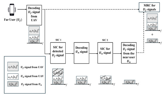
The near user forwards the far user’s signal using FD relaying while simultaneously receiving the new NOMA superposed signal from the UAV. Consequently, obtains two copies of its information: the first directly from the UAV and the second from the near user after a slight delay. Accordingly, the received signal at can be expressed as
where is the additive white Gaussian noise (AWGN). As shown in the above equation and Figure 2, the received signal at the far user consists of three signals: (1) the signal for the far user in the combined signal from the UAV’s superposed NOMA transmission; (2) the signal for the near user from the same NOMA UAV transmission; and (3) the relayed version of forwarded by the near user with a one-timeslot delay. Unlike conventional approaches, this work consider the relayed signal from the near user as interference when decoding the NOMA signal from the UAV. As in conventional NOMA, more power is allocated to the far user than the near user . Therefore, first attempts to decode its own signal from the UAV transmission while treating both the near user’s signal and the relayed signal from as interference. Consequently, the received SINR at for decoding its signal from the UAV can be given as
Figure 2.
Feasible SIC condition in UAV-assisted FD C-NOMA systems.
Subsequently, the far user applies SIC to eliminate the NOMA signal and isolate the near user’s signal, which is then decoded and removed from the combined signal. Finally, the far user decodes the relayed signal transmitted from the near user without interference. With the power control strategy introduced in the following section, the direct link from the UAV to (link n) is guaranteed to have higher transmission power than the cooperative relaying link (link ). Therefore, the received SINR at for detecting the near user’s signal is written as
After successfully detecting the near user’s signal , it is eliminated from the received signal through a second stage of SIC. Subsequently, the far user decodes the relayed signal from the near user without any interference. Therefore, the resulting received SNR can be expressed as
4. Power Control of Cooperative Transmission
In this section, a power control mechanism is introduced to adaptively adjust and guarantee feasible SIC, aiming to mitigate the impact of SI and ensure that the cooperative link’s SNR does not surpass the SINR at for decoding the signal intended for . The relaying power is determined based on the minimum achievable rate between the cooperative link from to and the direct link from the UAV to to detect signal. As a result, link n consistently has higher power than than , enabling to the use of the practical SIC. The power control of of transmit power is given in the following proposition.
Proposition 2.
The power control of transmit power to apply cooperative transmission is expressed as
Proof.
It is worth noting that we use a Fixed Power Allocation (FPA) for , , and . These values are then used to obtain the power allocation to maximize the minimum achievable user rate. After that, the power control is calculated again based on the new values of and to find the final solution.
5. Problem Formulation and Power Allocation for UAV-Assisted Full-Duplex Cooperative NOMA
This section presents the problem formulation and derives the power allocation scheme aimed at maximizing the minimum achievable rate.
5.1. Problem Formulation
In this subsection, the power allocation problem of the proposed system employing SWIPT is addressed. The primary objective of C-NOMA is to enhance the far user’s achievable rate. Consequently, the aim of this study is to maximize the minimum achievable rate across all users in the network. Mathematically, this power allocation problem is formulated as the following optimization problem
where is the maximum UAV transmission power, and constraints (17b) and (17c) represent the maximum power constraint to ensure that the allocated power is always positive. It is evident that the optimization problem (17) is non-convex due to the non-convex nature of its objective function. To solve this problem, is firstly obtained from the power control mechanism proposed in the last section. After examining the characteristics of Problem (17), the following proposition is presented.
Proposition 3.
With a given , problem (17) is quasi-concave.
Proof.
Given that is constant, the problem can be reformulated as a quasi-concave problem, as demonstrated in Appendix A. □
As a result, based on Proposition 3, the closed-form expression is derived by reformulating the problem as a sequence of convex feasibility problems to determine the optimal solution [35]. Therefore, the feasibility optimization problem is expressed as
5.2. Power Allocation
In this subsection, the optimal power allocation and the closed form power allocation solution for the proposed UAV-assisted FD C-NOMA system employing SWIPT are derived. Firstly, the following theorem is established to obtain the optimal power allocation.
Theorem 2.
The optimal solution to problem (19) for a given φ is written as
where , and indicate the Max–Min SINR.
Proof.
It can be observed that problem (19) is convex, as both the objective function and its constraints are convex because of their linear nature. Consequently, it is necessary to derive the the Lagrangian function corresponding to the optimization problem (19), which can be written as
in which , , and are the Lagrange multipliers corresponding to (19c) and (19d). By differentiating against and , the Karush–Kuhn–Tucker (KKT) conditions is derived and given as
From (26), it is clear that because is strictly a positive value. Also, due to NOMA transmission and the requirement for feasible SIC, is always larger than . Therefore, as both and are positive and equal to one. Also, due to (25) and (26) because all power is positive. As , (25) and (26) can be can equated to obtain the optimal power allocation. As a result of rearranging Equations (25) and (26), and are obtained as
In order to obtain the closed-form power allocation solution in (20) and (21), needs to be solved to obtain the closed-form result of the optimization problem. Therefore, Theorem 3 is obtained to solve .
Theorem 3.
The closed form power allocation solution for the original optimization problem (17) is given by (20) and (21), where the optimal β is written as
where and
Proof.
Finally, the power allocation to maximize the minimum achievable rate for both users can be calculated directly in closed-form by substituting (29) into (20) and (21). To further enhance the performance, the updated values of and is substituted into (16) to resolve again. Using the new relayed transmission power, β in (29) is calculated and substituted into (20) and (21) to obtain the optimal closed-form power allocation solution. The process of obtaining the final closed-form solution for the proposed scheme is illustrated in Figure 3. The closed-form power allocation is solved directly, and all parameters are obtained through direct substitution. Therefore, the computational complexity is constant, .
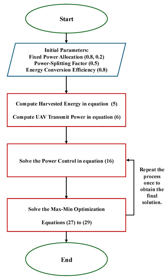
Figure 3.
Flowchart of the Max–Min Optimization Process.
6. Simulation Results
This paper investigates a UAV-assisted C-NOMA system with SWIPT consisting of a BS, a relayed UAV, and two users, denoted as and . The system parameters, including the models for the path loss and shadowing used in this paper are summarized in Table 1. Numerical simulation results for the proposed system model are presented in this section, including evaluations of the sum rate, individual far user rate, and outage probability. This section compares the performance of the proposed FD C-NOMA scheme with Max–Min against FPA FD C-NOMA, FD C-NOMA with Fractional Transmit Power Allocation (FTPA) [36], HD C-NOMA, and conventional NOMA. The energy conversion efficiency is set to 0.8 and power-splitting factor is fixed at 0.5. The SI is assumed to experience independent and identically distributed (i.i.d) Rician fading with a Rician factor of 5 dB [37]. In addition, the Rician factor for the BS-UAV link is 10 dB, and 6 dB for the links between the UAV and both NOMA users. The channel model and parameters for all communication links are shown in Table 2. The FPA power allocation ratio of and is and , respectively.

Table 1.
Simulation Parameters.
Table 2.
Channel Models and Parameters for Different Communication Links.
Figure 4 shows the achievable far user rate performance versus , with ranging from 20 dBm to 40 dBm. The far user is analyzed first since the main objective of C-NOMA is to enhance the performance of the weaker user. It is important to highlight that the proposed power control method is implemented in all schemes, including FD-FTPA and FD-FPA. It can be seen that the proposed FD schemes outperforms the HD and conventional NOMA. This is due to the use of FD cooperation and power control approach. The results also show that the proposed Max–Min power allocation for FD C-NOMA outperform FTPA and FPA FD C-NOMA schemes. This improvement occurred because the proposed approaches are designed to maximize the minimum achievable rate particularly for the far user which has the worst channel conditions. Moreover, the Max–Min performance improves after the second iteration, where the power control in (16) is recalculated using the updated value of and in (20) and (21). Then, the new is used to resolve and again, leading to the final solution. It is clear that the Max–Min final solution outperforms all other schemes, leading to enhance the far user rate.
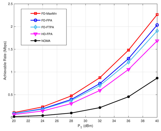
Figure 4.
Far user rate performance versus .
Figure 5 illustrates the achievable sum rate performance versus . The proposed FD scheme attains significantly better sum rate performance compared to the HD C-NOMA and the conventional NOMA because of applying FD technique. The FD cooperation enables the near user to achieve a higher rate while assisting the far user in improving its performance. The HD C-NOMA scheme performs better than conventional NOMA because of using cooperative communication. The proposed FD C-NOMA with Max–Min achieves a slightly lower sum rate than FPA, as its objective is to maximize the minimum achievable rate and guarantee that the near user and far user meet the minimum target rate. This leads to enhance the far user rate while maintaining a sum rate close to the FPA scheme. Although the FTPA scheme achieves the highest sum rate among all schemes, its far user performance is significantly worse, which limits the effectiveness of cooperative communication.
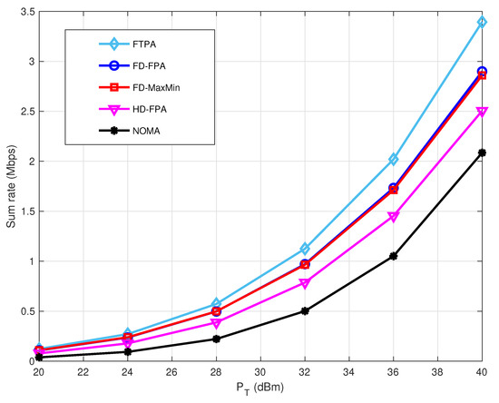
Figure 5.
Sum rate performance versus .
Figure 6 provides the achievable far user rate performance versus the UAV- distance , which varies from 100 m to 300 m. It is important to note that the D2D user pair separation is maintained at approximately 25 m in all cases to investigate effect of the UAV position. The proposed FD scheme always achieves higher rates compared to HD C-NOMA and NOMA. Moreover, the proposed FD C-NOMA with Max–Min outperforms the other schemes across all distances. While the performance of FD-FPA and FD-FTPA is close at larger distances, the Max–Min approach continues to achieve better results. This is because the Max–Min power allocation factors are adaptive and depend on the channel conditions.
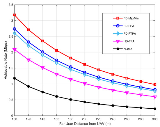
Figure 6.
Far user rate performance versus .
Figure 7 depicts the achievable far user rate performance versus the BS-UAV distance , which varies from 100 m to 1000 m. It is important to note that while the BS-UAV distance increases, the D2D user pair separation from the UAV remains fixed, as given in Table 1. This is done to investigate whether the far user performance is more degraded by increasing the BS-UAV separation or the UAV-user separation. A comparison of Figure 6 and Figure 7 shows that the far user achieves better performance when the BS-UAV distance is increased, rather than when the UAV-user distance is increased. The main reason is that the BS-UAV link is assumed to be LoS and the UAV is powered by the BS, whereas both NOMA users experience stronger shadowing and receive lower power from the UAV compared to the BS. Furthermore, the proposed FD scheme consistently achieves higher rates compared to HD C-NOMA and conventional NOMA. In addition, the proposed FD C-NOMA with Max–Min outperforms all other schemes across the entire range of distances.
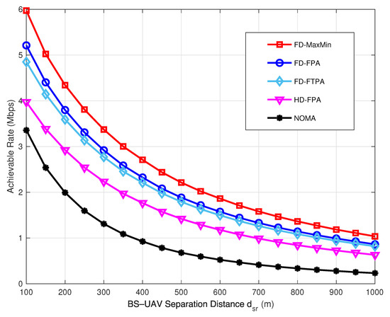
Figure 7.
Far user rate performance versus BS-UAV Separation .
The achievable far user rate performance versus the UAV altitude is evaluated in Figure 8. The UAV altitude is ranged from 40 m to 200 m and is fixed at 40 dBm. In the proposed system model, the UAV altitude is set to 100 m to ensure the LoS link and to achieve a reasonable rate performance. Even at higher UAV altitudes, the proposed schemes can maintain high performance without draining the UAV’s power, because of using SWIPT. It is clear that the proposed FD C-NOMA schemes achieve superior performance compared to both HD C-NOMA and conventional NOMA across all UAV altitudes. In particular, the FD C-NOMA with Max–Min consistently outperforms the other schemes, demonstrating its ability to achieve higher target rates under different scenarios. The far user rate is always improved with FD Max–Min, as the power allocation dynamically adapts to the channel coefficients.
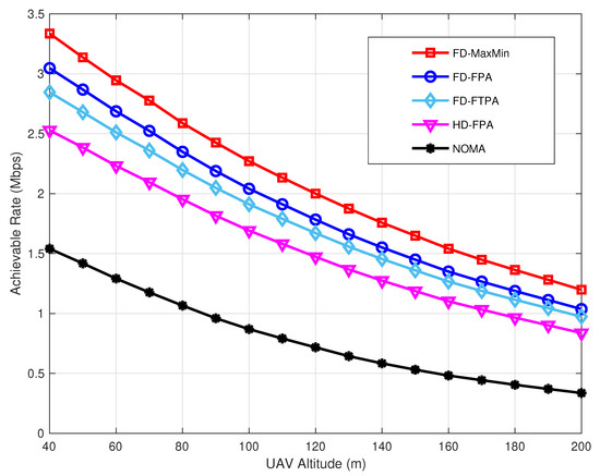
Figure 8.
Far user rate performance versus UAV Altitude.
The achievable far user rate performance versus the power-splitting factor when is fixed at 40 dBm is evaluated in Figure 9. It should be noted that when , all received power is allocated to energy harvesting, whereas when , all power is used for information decoding. The results clearly show that the proposed FD C-NOMA schemes perform better than the other schemes. Furthermore, FD C-NOMA with Max–Min outperforms FD-FPA and FD-FTPA, because of its adaptive Max–Min power allocation. In the proposed system model, is set to 0.5, meaning that half of the received power is allocated to energy harvesting and the other half to information decoding. This is because the target is to achieve higher rate with greater fairness. In addition, by comparing the cases of and , it is evident that the performance difference is small, and hence, allocating half the power to information decoding is preferable over a small rate improvement.
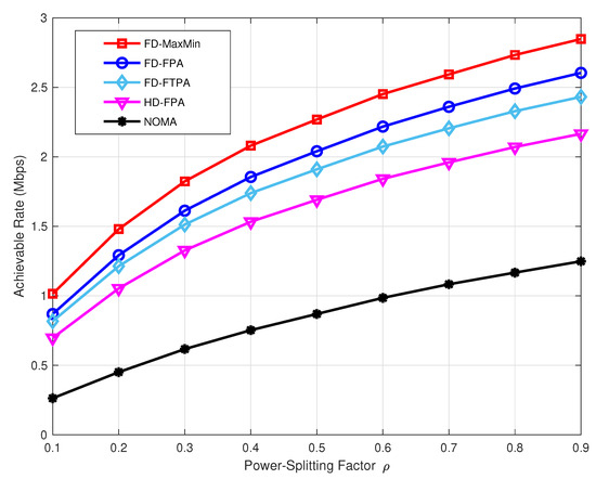
Figure 9.
Far user rate performance versus power-splitting factor .
Finally, Figure 10 shows the outage probability as a function of the minimum target rate when is fixed at 40 dBm. It is clear that the proposed FD schemes perform better than both HD C-NOMA and conventional NOMA. In particular, the FD scheme with Max–Min optimization achieves the lowest outage probability, especially in the low outage region. Therefore, the proposed schemes can support higher target rates while maintaining low outage, enhancing their effectiveness for C-NOMA systems.
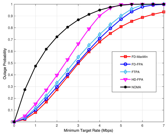
Figure 10.
Outage probability versus minimum target rate.
7. Conclusions
This paper explores the potential of UAV-assisted FD C-NOMA in a practical scenario to enhance the user rate performance. Both users are located beyond the BS coverage area and served using a flying UAV. The UAV is deployed using SWIPT to send the NOMA signals for both users and meet the high demand of transmission power. Additionally, the study investigated the power allocation strategy aimed at maximizing the minimum achievable rate for a practical UAV-assisted FD C-NOMA system employing SWIPT. Unlike conventional C-NOMA, this work proposed a detection order for decoding the far user signal from the UAV and the near user using a practical SIC operation. Also, a power control mechanism is proposed to adapt the near user transmission power dynamically, ensuring a reliable link for the far user. Specifically, the strategy guarantees that the SINR of the cooperative link does not surpass the SINR at the near user when detecting the far user’s information. This control mechanism reduces the SI effect at the near user, thereby enhancing the overall performance. Furthermore, the power control approach is employed to solve the optimization problem. Numerical simulation results show that the proposed scheme outperforms the HD C-NOMA and conventional NOMA. Finally, the proposed FD C-NOMA with Max–Min optimization outperforms all other schemes in terms of achievable rate, as the power allocation factors are adaptive and depend on channel gains.
Future work will consider several practical scenarios. First, the impact of imperfect SIC detection will be explored to evaluate system robustness. Second, imperfect CSI will be investigated to assess the effect of estimation accuracy and the utilization of time and energy resources. Third, the integration of MIMO and TAS techniques will be studied to exploit array gains, improve the Max–Min achievable rate, and reduce the SI effect. Finally, optimization of a variable power-splitting factor will be investigated to enhance the overall performance, balance energy harvesting and information decoding, and reduce SI effect.
Funding
The authors would like to acknowledge the Deanship of Graduate Studies and Scientific Research, Taif University for funding this work.
Data Availability Statement
The original contributions presented in this study are included in the article. Further inquiries can be directed to the corresponding author.
Acknowledgments
The authors would like to acknowledge the Deanship of Graduate Studies and Scientific Research, Taif University for funding this work.
Conflicts of Interest
The author declares no conflicts of interest.
Abbreviations
The following abbreviations are used in this manuscript:
| UAVs | Unmanned aerial vehicles |
| 6G | Sixth generation |
| BS | Base Station |
| QoS | Quality of Service |
| NTN | Non-terrestrial network |
| DF | Decode-and-Forward |
| NOMA | Non-orthogonal Multiple Access |
| NGMA | Next-generation multiple access |
| SWIPT | Simultaneous wireless information and power transfer |
| FD | Full-duplex |
| HD | Half-duplex |
| C-NOMA | Cooperative NOMA |
| MIMO | Multiple-input multiple-output |
| TAS | Transmit antenna selection |
| SIC | Successive interference cancellation |
| MRC | Maximal ratio combining |
| D2D | Device-to-device |
| SI | Self-interference |
| Max-Min | Maximize minimum achievable rate |
| CSI | Channel state information |
| LoS | Line-of-sight |
| NLoS | non-LoS |
| AWGN | Additive white Gaussian noise |
| SINR | Signal-to-interference-plus-noise ratio |
| SNR | Signal-to-noise ratio |
| FPA | Fixed power allocation |
| FTPA | Fractional transmit power allocation |
| KKT | Karush-Kuhn-Tucker |
Appendix A. Proof of the Quasi-Concavity of Problem the Objective Function (17)
Following [35], the optimization problem is quasi-concave when the objective function itself is quasi-concave and the constraints are convex. Constraints (17b) and (17c) are convex since they are linear. To establish that the objective function is quasi-concave, it is necessary to show that all its superlevel sets are convex. After straightforward derivations, the objective function in (17) can be reformulated into the following linear expressions.
where Thus, the objective function is quasi-concave, as all superlevel sets are convex.
References
- Zhang, Z.; Xiao, Y.; Ma, Z.; Xiao, M.; Ding, Z.; Lei, X.; Karagiannidis, G.K.; Fan, P. 6G Wireless Networks: Vision, Requirements, Architecture, and Key Technologies. IEEE Veh. Technol. Mag. 2019, 14, 28–41. [Google Scholar] [CrossRef]
- Hayat, S.; Yanmaz, E.; Muzaffar, R. Survey on Unmanned Aerial Vehicle Networks for Civil Applications: A Communications Viewpoint. IEEE Commun. Surv. Tutor. 2016, 18, 2624–2661. [Google Scholar] [CrossRef]
- Rinaldi, F.; Maattanen, H.L.; Torsner, J.; Pizzi, S.; Andreev, S.; Iera, A.; Koucheryavy, Y.; Araniti, G. Non-Terrestrial Networks in 5G & Beyond: A Survey. IEEE Access 2020, 8, 165178–165200. [Google Scholar] [CrossRef]
- Li, B.; Fei, Z.; Zhang, Y. UAV Communications for 5G and Beyond: Recent Advances and Future Trends. IEEE Internet Things J. 2019, 6, 2241–2263. [Google Scholar] [CrossRef]
- Liu, Y.; Zhang, S.; Mu, X.; Ding, Z.; Schober, R.; Al-Dhahir, N.; Hossain, E.; Shen, X. Evolution of NOMA Toward Next Generation Multiple Access (NGMA) for 6G. IEEE J. Sel. Areas Commun. 2022, 40, 1037–1071. [Google Scholar] [CrossRef]
- Makki, B.; Chitti, K.; Behravan, A.; Alouini, M.S. A Survey of NOMA: Current Status and Open Research Challenges. IEEE Open J. Commun. Soc. 2020, 1, 179–189. [Google Scholar] [CrossRef]
- Maraqa, O.; Rajasekaran, A.S.; Al-Ahmadi, S.; Yanikomeroglu, H.; Sait, S.M. A Survey of Rate-Optimal Power Domain NOMA with Enabling Technologies of Future Wireless Networks. IEEE Commun. Surv. Tutor. 2020, 22, 2192–2235. [Google Scholar] [CrossRef]
- Islam, S.M.R.; Avazov, N.; Dobre, O.A.; Kwak, K.-s. Power-Domain Non-Orthogonal Multiple Access (NOMA) in 5G Systems: Potentials and Challenges. IEEE Commun. Surv. Tutor. 2017, 19, 721–742. [Google Scholar] [CrossRef]
- Ding, Z.; Lei, X.; Karagiannidis, G.K.; Schober, R.; Yuan, J.; Bhargava, V.K. A Survey on Non-Orthogonal Multiple Access for 5G Networks: Research Challenges and Future Trends. IEEE J. Sel. Areas Commun. 2017, 35, 2181–2195. [Google Scholar] [CrossRef]
- Ding, Z.; Peng, M.; Poor, H.V. Cooperative Non-Orthogonal Multiple Access in 5G Systems. IEEE Commun. Lett. 2015, 19, 1462–1465. [Google Scholar] [CrossRef]
- Liu, Y.; Ding, Z.; Elkashlan, M.; Poor, H.V. Cooperative Non-orthogonal Multiple Access with Simultaneous Wireless Information and Power Transfer. IEEE J. Sel. Areas Commun. 2016, 34, 938–953. [Google Scholar] [CrossRef]
- Zhang, Z.; Ma, Z.; Xiao, M.; Ding, Z.; Fan, P. Full-Duplex Device-to-Device-Aided Cooperative Nonorthogonal Multiple Access. IEEE Trans. Veh. Technol. 2017, 66, 4467–4471. [Google Scholar] [CrossRef]
- Alsaba, Y.; Leow, C.Y.; Abdul Rahim, S.K. Full-Duplex Cooperative Non-Orthogonal Multiple Access with Beamforming and Energy Harvesting. IEEE Access 2018, 6, 19726–19738. [Google Scholar] [CrossRef]
- Liu, G.; Chen, X.; Ding, Z.; Ma, Z.; Yu, F.R. Hybrid Half-Duplex/Full-Duplex Cooperative Non-Orthogonal Multiple Access with Transmit Power Adaptation. IEEE Trans. Wirel. Commun. 2018, 17, 506–519. [Google Scholar] [CrossRef]
- Al-Ahmadi, S. On the Achievable Max-Min Rates of Cooperative Power-Domain NOMA Systems. IEEE Access 2020, 8, 173112–173122. [Google Scholar] [CrossRef]
- Men, J.; Ge, J.; Zhang, C. Performance Analysis for Downlink Relaying Aided Non-Orthogonal Multiple Access Networks with Imperfect CSI Over Nakagami-m Fading. IEEE Access 2017, 5, 998–1004. [Google Scholar] [CrossRef]
- Dinh, P.; Arfaoui, M.A.; Sharafeddine, S.; Assi, C.M.; Ghrayeb, A. A Low-Complexity Framework for Joint User Pairing and Power Control for Cooperative NOMA in 5G and Beyond Cellular Networks. IEEE Trans. Commun. 2020, 68, 6737–6749. [Google Scholar] [CrossRef]
- Aswathi, V.; Babu, A.V. Outage and Throughput Analysis of Full-Duplex Cooperative NOMA System with Energy Harvesting. IEEE Trans. Veh. Technol. 2021, 70, 11648–11664. [Google Scholar] [CrossRef]
- Mozaffari, M.; Saad, W.; Bennis, M.; Nam, Y.H.; Debbah, M. A Tutorial on UAVs for Wireless Networks: Applications, Challenges, and Open Problems. IEEE Commun. Surv. Tutor. 2019, 21, 2334–2360. [Google Scholar] [CrossRef]
- Wang, J.; Jiang, C.; Han, Z.; Ren, Y.; Maunder, R.G.; Hanzo, L. Taking Drones to the Next Level: Cooperative Distributed Unmanned-Aerial-Vehicular Networks for Small and Mini Drones. IEEE Veh. Technol. Mag. 2017, 12, 73–82. [Google Scholar] [CrossRef]
- Wan, X.; Yang, X.; Wang, Z.; Fan, Z.; Duo, B. Sum Rate Optimization Scheme of UAV-Assisted NOMA under Hardware Impairments. Appl. Sci. 2023, 13, 2971. [Google Scholar] [CrossRef]
- Arzykulov, S.; Celik, A.; Nauryzbayev, G.; Eltawil, A.M. UAV-Assisted Cooperative & Cognitive NOMA: Deployment, Clustering, and Resource Allocation. IEEE Trans. Cogn. Commun. Netw. 2022, 8, 263–281. [Google Scholar] [CrossRef]
- Mu, G. Joint beamforming and power allocation for wireless powered UAV-assisted cooperative NOMA systems. EURASIP J. Wirel. Commun. Netw. 2020, 2020, 55. [Google Scholar] [CrossRef]
- Amhaz, A.; Elhattab, M.; Sharafeddine, S.; Assi, C. UAV-Assisted Cooperative Downlink NOMA: Deployment and Resource Allocation. IEEE Trans. Veh. Technol. 2024, 73, 13651–13664. [Google Scholar] [CrossRef]
- Ullah, Y.; Adeoye, I.O.; Roslee, M.; Ismail, M.A.; Ali, F.; Ahmad, S.; Osman, A.F.; Ali, F.Z. DDPG-Based UAV-RIS Framework for Optimizing Mobility in Future Wireless Communication Networks. Drones 2025, 9, 437. [Google Scholar] [CrossRef]
- Ahmad, S.; Zhang, J.; Khan, A.; Ali, I.; Hayat, B.; Tian, Y. Learning-Based Power Minimization in Secure Multiple UAV-Aided MIMO Networks. IEEE Trans. Consum. Electron. 2025, 71, 4277–4291. [Google Scholar] [CrossRef]
- He, Y.; Huang, F.; Wang, D.; Zhang, R. Outage Probability Analysis of MISO-NOMA Downlink Communications in UAV-Assisted Agri-IoT with SWIPT and TAS Enhancement. IEEE Trans. Netw. Sci. Eng. 2025, 12, 2151–2164. [Google Scholar] [CrossRef]
- Cao, Z.; Yan, P.; Li, B.; Zou, Y.; Li, C.; Zhang, G.; Dang, S. Employing Artificial Noise for Secure NOMA-Aided UAV Transmissions. IEEE Internet Things J. 2025, 12, 2279–2282. [Google Scholar] [CrossRef]
- Alhulayil, M.; Abu Aqoulah, M.; López-Benítez, M.; Al-Mistarihi, M.F.; Alammar, M.; Al Ayidh, A. Integrated THz/mmWave Transmission Method for Enhanced URLLC Communications. IEEE Access 2025, 13, 62914–62929. [Google Scholar] [CrossRef]
- Alharbi, T.E.A.; So, D.K.C. Full-Duplex Decode-and-Forward Cooperative Non-Orthogonal Multiple Access. In Proceedings of the 2018 IEEE 87th Vehicular Technology Conference (VTC Spring), Porto, Portugal, 3–6 June 2018; pp. 1–6. [Google Scholar] [CrossRef]
- Alharbi, T.E.A.; Shen, K.Z.; So, D.K.C. Full-Duplex Cooperative Non-Orthogonal Multiple Access System with Feasible Successive Interference Cancellation. In Proceedings of the 2020 IEEE 91st Vehicular Technology Conference (VTC2020-Spring), Antwerp, Belgium, 25–28 May 2020; pp. 1–6. [Google Scholar]
- Muruganathan, S.D.; Lin, X.; Määttänen, H.L.; Sedin, J.; Zou, Z.; Hapsari, W.A.; Yasukawa, S. An overview of 3GPP release-15 study on enhanced LTE support for connected drones. IEEE Commun. Stand. Mag. 2021, 5, 140–146. [Google Scholar] [CrossRef]
- Xu, Y.; Zhang, T.; Yang, D.; Liu, Y.; Tao, M. Joint resource and trajectory optimization for security in UAV-assisted MEC systems. IEEE Trans. Commun. 2020, 69, 573–588. [Google Scholar] [CrossRef]
- Liu, L.; Zhang, R.; Chua, K. Wireless Information and Power Transfer: A Dynamic Power Splitting Approach. IEEE Trans. Commun. 2013, 61, 3990–4001. [Google Scholar] [CrossRef]
- Boyd, S.; Vandenberghe, L. Convex Optimization; Cambridge University Press: Cambridge, UK, 2004. [Google Scholar]
- Benjebbovu, A.; Li, A.; Saito, Y.; Kishiyama, Y.; Harada, A.; Nakamura, T. System-level performance of downlink NOMA for future LTE enhancements. In Proceedings of the 2013 IEEE Globecom Workshops (GC Wkshps), Atlanta, GA, USA, 9–13 December 2013; pp. 66–70. [Google Scholar] [CrossRef]
- Zhang, Z.; Long, K.; Vasilakos, A.V.; Hanzo, L. Full-Duplex Wireless Communications: Challenges, Solutions, and Future Research Directions. Proc. IEEE 2016, 104, 1369–1409. [Google Scholar] [CrossRef]


Disclaimer/Publisher’s Note: The statements, opinions and data contained in all publications are solely those of the individual author(s) and contributor(s) and not of MDPI and/or the editor(s). MDPI and/or the editor(s) disclaim responsibility for any injury to people or property resulting from any ideas, methods, instructions or products referred to in the content. |
© 2025 by the author. Licensee MDPI, Basel, Switzerland. This article is an open access article distributed under the terms and conditions of the Creative Commons Attribution (CC BY) license (https://creativecommons.org/licenses/by/4.0/).