Article

H Performance of FlexRay Protocol-Based Networked Control Systems Subjected to Randomly Occurring Cyber Attacks

School of Science, Jiangnan University, Wuxi 214122, China
*
Author to whom correspondence should be addressed.
Mathematics 2025, 13(21), 3515; https://doi.org/10.3390/math13213515
Submission received: 12 October 2025 / Revised: 28 October 2025 / Accepted: 30 October 2025 / Published: 2 November 2025
(This article belongs to the Section E: Applied Mathematics)

Abstract

This paper investigates the mean square exponential stability (MSES) and H performance analysis of discrete networked control systems (NCSs) based on the FlexRay protocol (FRP) when confronted with randomly occurring cyber attacks (ROCAs). In order to deal with network congestion due to the limited bandwidth, the FRP is used to schedule the information exchange. Besides, a comprehensive attack model is built by simultaneously considering false data injection (FDI) attacks and denial-of-service (DoS) attacks. Then, a mode-dependent output feedback controller is designed on this basis. Furthermore, sufficient conditions for the MSES and H performance of the considered system are derived under the mode-dependent Lyapunov function and average dwell time (ADT) constraints. Subsequently, the controller gains of two modes are determined by solving the recursive linear matrix inequalities (RLMIs) and the FRP-based MSES algorithm is also presented. The simulation verifies that the proposed algorithm maintains the system stability with good robustness and H performance under ROCAs.

1. Introduction

With the advancements in industrial automation and communication control technology, NCSs have gained wide adoption in engineering practice, owing to their advantages such as real-time performance, distributed architecture, scalability, ease of maintenance, and relatively low installation costs. These systems can flexibly adapt to increasingly complex and diverse application scenarios [1,2], achieving remarkable results across a range of fields, including sensor networks [3], power grids [4], autonomous vehicles [5] and geological exploration [6]. NCSs rely on shared communication networks to interconnect their components and enable the exchange of information. However, there are a series of challenges introduced in the network transmission, such as packet dropouts, cyber attacks, signal quantization, and other network-induced phenomena, which puts higher demands on the system stability and thus arouses a wide range of academic concerns about the stability of NCSs [7,8,9,10,11].
Currently, the automotive industry is moving towards autonomous driving and intelligent connected vehicles. Nevertheless, the openness and interconnectivity of NCSs also heighten the risk of cyber attacks, potentially compromising system performance and even disrupting system stability. For example, in 2015, Ukraine experienced large-scale cyber attacks that caused widespread power outages in several regions, affecting thousands of users [12]. While cyber attacks must be condemned, it is also of crucial importance to investigate the stability of NCSs that are exposed to cyber attacks. In recent decades, the modeling and in-depth study of cyber attacks have consistently been a research hotspot, with numerous research results on cyber attack issues being reported [13,14,15,16,17,18]. Cyber attacks can affect one of the CIA (Confidentiality, Integrity and Availability). Specifically, DoS attacks affect availability by flooding the target with a large volume of data, which depletes system resources or causes network congestion, ultimately rendering the system unable to provide normal services [15,16]. FDI attacks compromise data integrity through manipulation of its contents, thereby affecting system decision-making and operation [17,18]. Although data breaches can also impact confidentiality, this study primarily concentrates on the system stability under DoS and FDI attacks. Moreover, in practical network environments, the attacks typically occur randomly. Inspired by the attack model presented in [19,20], Bernoulli distributions are used to model the FDI attacks as well as the DoS attacks.
In addition to cyber security issues, network congestion has emerged as another significant challenge which urgently requires resolution. Network congestion and other network-induced phenomena become inevitable owing to the limited network bandwidth when a substantial quantity of data is accessed simultaneously on the network, posing serious challenges to the system stability. To effectively tackle network congestion problem and alleviate network burden, selecting an appropriate communication protocol has become even more crucial. In the existing literature, a variety of communication protocols have been extensively studied, including the try-once-discard protocol (TODP) [20,21], round-robin protocol (RRP) [22,23], and stochastic communication protocol (SCP) [24,25].
It is worth mentioning that FRP has received widespread attention due to its reliability and flexibility of data transmission in public network channels [26]. The FRP is a hybrid protocol that sends data packets during a predetermined communication cycle, which consists of regularly repeating static and dynamic segments [27]. Compared to other protocols, the FRP combines the advantages of time-triggered protocols (such as RRP) and event-triggered protocols (such as TODP), achieving reliable transmission of periodic data while dynamically adjusting data transmission based on event priority. Especially in the context of cyber attacks, the scheduling strategy may help improve the management of data transmission. Furthermore, the FRP has been proven to have faster, more flexible, and more reliable characteristics [28] and has achieved some preliminary results [26,29,30,31]. However, it is noteworthy that research on the FRP in the existing literature is limited, with the majority of studies focusing on continuous systems [27,28,32]. Despite the aforementioned research, the stability of discrete NCSs with the FRP has not been given enough attention, let alone the study of the effects of ROCAs on the system stability, which provides inspiration for our research.
In recent decades, common control methods primarily include H control [33,34,35,36], event-triggered control [37,38], fuzzy control [39,40], and so on. For example, in [33], a static output feedback H 2 / H fault-tolerant control strategy was proposed for nonlinear NCSs to address hybrid cyber attacks and hybrid-triggered mechanisms. However, these control methods do not fully consider the transmission characteristics and the real-time requirements of FRP, particularly in time-varying systems, and thus cannot be directly applicable to the model discussed in this paper. In contrast, the mode-dependent output feedback controller can flexibly adjust the controller gain based on the system’s current mode, ensuring good robustness in different modes and thus better aligning with the objective of this paper.
Upon reviewing the existing literature, the following significant observations can be drawn: (1) most studies primarily focus on the stability analysis of systems under a single communication protocol when subjected to cyber attacks [41,42], yet it does not delve into the system stability when two protocols, RRP and TODP, are involved in a communication cycle, especially when switching between the static and dynamic segments; and (2) most of the literature on FRP considers only a single fixed attack mode. Compared to a single fixed attack mode [43,44], ROCAs exhibit uncertainty and diversity, and their attack behavior is characterized by randomness and unpredictability in time, which can easily lead to the failure of traditional protection strategies and cause greater impact on the system stability and security [45,46]. Although the literature [47] studies the combination of FRP and hybrid cyber attacks, which primarily focuses on the system filtering problem, this paper specifically addresses the system stability issue, considering a distinct type of system and employing a different modeling approach for DoS attacks. Therefore, the conclusions of existing research are not applicable to the research question of this article. To address this, a more comprehensive and in-depth approach is urgently needed to investigate the stability of NCSs under the simultaneous consideration of the FRP and ROCAs.
In light of this, it is clear that we need to study in depth the transmission characteristics and components of the FRP within a communication cycle, with a particular focus on the stability when switching between static and dynamic segments. Specifically, we need to evaluate the system stability separately in the RRP and TODP modes, especially at the switching points. Therefore, when designing the output feedback controller, we must select an appropriate one based on the current system mode. To this end, a mode-dependent output feedback controller is proposed to make the system achieve MSES and satisfy the H performance. Compared with existing methods, the proposed controller design approach is less conservative and more flexible in dealing with system changes, making it of great practical significance.
Inspired by the abovementioned discussions, this article endeavors to present a FRP-based MSES algorithm for NCSs subjected to ROCAs. Below, we discuss the primary challenges encountered in this paper during the study of achieving MSES for the system.
  • How to construct a suitable switched system model to take full account for the transmission characteristics of the FRP and the impact of ROCAs?
  • How to make sure the system is stable when switching between the static and dynamic segments, especially at the switching point?
  • How to design a practical algorithm to calculate the controller gains?
To confront the challenges outlined above, the main contributions of the study are given as follows.
  • The closed-loop switched system with a mode-dependent output feedback controller is investigated for the first time within the framework of stability analysis, where the signal is transmitted by the FRP and the system is subjected to ROCAs.
  • Sufficient conditions for the MSES and H performance of the switched system are developed by utilizing a mode-dependent Lyapunov function in conjunction with the ADT approach. These conditions are employed to determine a set of matrices P ȷ ( ς ) ( ς ) instead of the conventional yet conservative matrix P ( ς ) . This approach serves to diminish conservatism while simultaneously ensuring the system stability when switching between the static and dynamic segments.
  • A FRP-based MSES algorithm, which is practical and feasible, is presented to determine the corresponding controller gain of each mode.
The subsequent sections of this paper are organized in the following manner. In Section 2, we construct a mode-dependent output feedback controller and a system model considering the characteristics of the FRP and the effects of ROCAs, and clearly state the primary objective of this paper. Section 3 derives in detail the sufficient conditions for the system stability and performance under ROCAs. Simultaneously, the specific expression for the controller gains are derived computationally. Section 4 demonstrates the effectiveness of the proposed theory and methodology by means of a specific simulation case. Section 5 highlights several possible directions for future research and extensions of this work. Finally, in Section 6, the study is summarized and conclusions are drawn.
Notations I n denotes the n-dimensional identify matrix. E { β } means the mathematical expectation of the random variable β . δ ( · ) represents the Kronecker delta function, such that δ ( a ) = 1 if a is equal to 0, and δ ( a ) = 0 for all other values of a. The notations of key variables and subscripts are summarized in Table 1.

2. Problem Formulation

2.1. System Model

As depicted in Figure 1a, the plant under consideration is as follows:
( ς + 1 ) = A ( ς ) ( ς ) + B ( ς ) N ( ς ) + E ( ς ) ϰ ( ς ) ð ( ς ) = C ( ς ) ( ς ) + D ( ς ) N ( ς ) O ( ς ) = F ( ς ) ( ς ) ,
where ( ς ) R n is the system state; ð ( ς ) R n ð is the measurement output measured by n ð sensors; ϰ ( ς ) R n ϰ is the control input; O ( ς ) R n O is the control output; N ( ς ) R n N represents the exogenous disturbance satisfying N ( ς ) L 2 [ 0 , + ) . A ( ς ) , B ( ς ) , C ( ς ) , D ( ς ) , E ( ς ) and F ( ς ) are time-varying matrices with appropriate dimensions.

2.2. FlexRay Protocol

In order to cope with network congestion, this paper adopts the FRP to schedule the data transmission between the sensor and the controller (as shown in Figure 1b, and at each time instant ς , as used in [26], only one sensor is allowed to transmit the signal. According to [26], transmission time is assumed to have negligible impact, and thus, it is also excluded from the analysis in our paper.
The communication cycle of the FRP with time length l 1 ( l 1 n ð ) , illustrated in Figure 1b, consists of a static segment dedicated to time-triggered scheduling, a dynamic segment dedicated to event-triggered scheduling, a symbol window, and a network idle time (NIT). The corresponding time lengths are set as Q 1 , Q 2 , Q 3 and Q 4 , respectively. The lengths of the symbol window and the NIT are considered negligible relative to Q 1 and Q 2 . Without loss of generality, they are neglected, i.e., Q 3 = Q 4 = 0 and assume that Q 1 = l n ð 2 , Q 2 = q ( l , q N ) , in which case l 1 = l + q . Further details can be found in [29].
It should be noted that owing to the different real-time requirements of each component in the measurement signal, components with high real-time requirements are scheduled with the RRP. Specifically speaking, it is assumed that the first l components of the measurement signal ð ( ς ) (i.e., ð ( 1 ) ( ς ) ) are scheduled by the RRP, while the rest of the components (i.e., ð ( 2 ) ( ς ) ) are scheduled by the TODP. In the light of the features of the FRP, the RRP is active during the static segments, while the TODP is executed during the dynamic segments.
For ease of expression, we denote
ð ( ς ) = ð ( 1 ) ( ς ) T , ð ( 2 ) ( ς ) T T , ð ¯ ( ς ) = ð ¯ ( 1 ) ( ς ) T , ð ¯ ( 2 ) ( ς ) T T ,
ð ( 1 ) ( ς ) = ð 1 ( ς ) , , ð l ( ς ) T , ð ( 2 ) ( ς ) = ð l + 1 ( ς ) , , ð n ð ( ς ) T ,
ð ¯ ( 1 ) ( ς ) = ð ¯ 1 ( ς ) , , ð ¯ l ( ς ) T , ð ¯ ( 2 ) ( ς ) = ð ¯ l + 1 ( ς ) , , ð ¯ n ð ( ς ) T .
In addition, time intervals of the static and dynamic segments are [ b l 1 + 1 , b l 1 + l ] and [ b l 1 + l + 1 , b l 1 + l + q ] ( b = 0 , 1 , 2 , ) , separately. For the sake of simplicity, the static segment interval [ b l 1 + 1 , b l 1 + l ] is abbreviated as S , and the dynamic segment interval [ b l 1 + l + 1 , b l 1 + l + q ] as D . The following will introduce the node selection rules in detail.
(1)
R R P :
σ ς mod ( ς 1 , l ) + 1 , ς S ,
where σ ς Z 1 { 1 , 2 , , l } represents the sensor node granted network access at time ς . For i Z 1 , through the zero-order holder (ZOH), there holds
ð ¯ i ( ς ) = ð i ( ς ) , i = σ ς , ς S ð ¯ i ( ς 1 ) , i σ ς , ς S 0 , ς D .
(2)
T O D P :
ξ ς min { arg max j = l + 1 , , n ð ð ˇ j T ( ς ) R j ð ˇ j ( ς ) } , ς D ,
where ξ ς Z 2 { l + 1 , , n ð } represents the sensor node granted network access at time ς and R j ( j Z 2 ) are weighted matrices, which are known positive definite matrices. Let ð ˇ j ( ς ) ð j ( 2 ) ( ς ) ð ¯ j ( 2 ) ( ς 1 ) , by virtue of the ZOH, ð ¯ j ( ς ) can be represented by
ð ¯ j ( ς ) = ð j ( ς ) , j = ξ ς , ς D ð ¯ j ( ς 1 ) , j ξ ς , ς D 0 , ς S .
It follows from (3) and (5) that one has
ð ¯ ( 1 ) ( ς ) = Φ σ ς ð ( 1 ) ( ς ) + ( I l Φ σ ς ) ð ¯ ( 1 ) ( ς 1 ) , ς S 0 , ς D ,
ð ¯ ( 2 ) ( ς ) = 0 , ς S Ω ξ ς ð ( 2 ) ( ς ) + ( I n ð l Ω ξ ς ) ð ¯ ( 2 ) ( ς 1 ) , ς D ,
where
Φ σ ς diag δ ( 1 σ ς ) , δ ( 2 σ ς ) , , δ ( l σ ς ) ,
Ω ξ ς diag δ ( l + 1 ξ ς ) , δ ( l + 2 ξ ς ) , , δ ( n ð ξ ς ) .
Remark 1.
At time instant ς, for RRP (TODP), only the component ð σ ς ( ς ) ( ð ξ ς ( ς ) ) of ð ( ς ) is updated, and the rest of the components are updated through the ZOH strategy, called segment-dependent ZOH strategy, which was firstly proposed in the literature [30].
Assumption 1.
The system starts from ς = 1 with ( 1 ) = 0 and ð ( 0 ) = 0 (i.e., zero initial condition), which is in the static segment, and the corresponding sensor node is σ 1 = 1 .
Remark 2.
To ease the process of the following analysis and derivation, suppose that the initial state ( 1 ) equals 0. Accordingly, the output ð ( ς 1 ) , which corresponds to ð ( 0 ) , is also assumed to be zero. In particular, this assumption does not affect the universality of the conclusions, as should be mentioned, and the results of the relevant analysis are equally valid for any initial condition [48,49].
To further enhance resource utilization efficiency and ensure data transmission quality, a switching signal is introduced to enable a smooth transition between the static and dynamic segments, denoted as ȷ ( ς ) :
ȷ ( ς ) 1 , ς S 0 , ς D .
According to (6), (7) and (8), we can obtain the measurement outputs under the FRP as bellow:
ð ¯ ( ς ) = ȷ ( ς ) I 1 ð ¯ ( 1 ) ( ς ) + ( 1 ȷ ( ς ) ) I 0 ð ¯ ( 2 ) ( ς ) = ȷ ( ς ) I 1 [ Φ σ ς ð ( 1 ) ( ς ) + ( I l Φ σ ς ) ð ¯ ( 1 ) ( ς 1 ) ] + ( 1 ȷ ( ς ) ) I 0 [ Ω ξ ς ð ( 2 ) ( ς ) + ( I n ð l Ω ξ ς ) ð ¯ ( 2 ) ( ς 1 ) ] = ȷ ( ς ) I 1 [ Φ σ ς I 1 T ð ( ς ) + ( I l Φ σ ς ) I 1 T ð ¯ ( ς 1 ) ] + ( 1 ȷ ( ς ) ) I 0 [ Ω ξ ς I 0 T ð ( ς ) + ( I n ð l Ω ξ ς ) I 0 T ð ¯ ( ς 1 ) ] = [ ȷ ( ς ) I 1 Φ σ ς I 1 T + ( 1 ȷ ( ς ) ) I 0 Ω ξ ς I 0 T ] ð ( ς ) + ȷ ( ς ) I 1 ( I l Φ σ ς ) I 1 T + ( 1 ȷ ( ς ) ) I 0 ( I n ð l Ω ξ ς ) I 0 T ð ¯ ( ς 1 ) ,
where
I 1 I l 0 ( n ð l ) × l , I 0 0 l × ( n ð l ) I n ð l .

2.3. Randomly Occurring Cyber Attacks

Taking the DoS attack and FDI attack into account on signal transmission, refer to Figure 1c, the actual measurement output is further written as:
ð ¯ ¯ ( ς ) = ν ς ð ¯ ( ς 1 ) + ( 1 ν ς ) ð ¯ ( ς ) + η ς ( ς ) = ν ς ð ¯ ( ς 1 ) + ( 1 ν ς ) ð ¯ ( ς ) + ( 1 ν ς ) η ς ( ς ) = ( 1 ν ς ) ȷ ( ς ) I 1 Φ σ ς I 1 T + ( 1 ȷ ( ς ) ) I 0 Ω ξ ς I 0 T ð ( ς ) + ν ς I n ð + ( 1 ν ς ) ȷ ( ς ) I 1 I l Φ σ ς I 1 T + ( 1 ȷ ( ς ) ) I 0 I n ð l Ω ξ ς I 0 T ð ¯ ( ς 1 ) + ( 1 ν ς ) η ς ( ς ) ,
where ( ς ) represents the false data injected by the attackers, ν ς and η ς are random Bernoulli distributed variables taking values of 0 or 1 with E { ν ς } = ν ¯ , E { η ς } = η ¯ .
Remark 3.
As in the literature [45], suppose that Bernoulli variables ν ς and η ς are uncorrelated with N ( ς ) and that ν ¯ and η ¯ are given known parameters.
Next, we will analyze the attack patterns of ROCAs and the corresponding system measurement output. It is noted that model (9) contains three special cases. Specifically, when ν ς = 0 and η ς = 0 the controller receives a normal signal that is not under attack; when ν ς = 1 the system suffers a DoS attack, the measurement signals cannot be updated, the last moment of transmission ð ¯ ( ς 1 ) is used as the actual measurement output signal; when ν ς = 0 and η ς = 1 , the system suffers a FDI attack, the actual measurement output is ð ¯ ( ς ) + ( ς ) .
Assumption 2.
Given a real constant matrix G , the following constraint should be satisfied for the occurrence of a FDI attack:
( ς ) 2 G ( ς ) .
Generally, attackers limit the energy of FDI attacks in order to enhance their stealthiness. Additionally, due to the physical constraints of NCSs and limited network bandwidth, the energy of FDI attacks is also constrained. Hence, it is reasonable to make such an assumption.

2.4. Controller Design

For system (1), we design the following controller:
ϰ ( ς ) = K ( ς ) ð ¯ ¯ ( ς ) ,
where ð ¯ ¯ ( ς ) represents the actual measurement output after the signal has been subjected to ROCAs during transmission and K ( ς ) is the controller gain to be determined. Then, substituting Equations (10) and (12) into (1) gives the closed-loop system state equation:
( ς + 1 ) = A ( ς ) ( ς ) + B ( ς ) N ( ς ) + E ( ς ) ϰ ( ς ) = A ( ς ) + E ( ς ) K ( ς ) ( 1 ν ς ) ȷ ( ς ) I 1 Φ σ ς I 1 T + ( 1 ȷ ( ς ) ) I 0 Ω ξ ς I 0 T C ( ς ) ( ς ) + B ( ς ) + E ( ς ) K ( ς ) ( 1 ν ς ) ȷ ( ς ) I 1 Φ σ ς I 1 T + ( 1 ȷ ( ς ) ) I 0 Ω ξ ς I 0 T D ( ς ) N ( ς ) + E ( ς ) K ( ς ) ν ς I n ð + ( 1 ν ς ) ȷ ( ς ) I 1 I l Φ σ ς I 1 T + ( 1 ȷ ( ς ) ) I 0 I n ð l Ω ξ ς I 0 T ð ¯ ( ς 1 ) + E ( ς ) K ( ς ) ( 1 ν ς ) η ς ( ς ) .

2.5. System Augmentation

Setting ¯ ( ς ) T ( ς ) ð ¯ T ( ς 1 ) T , then, an augmented system of (13) can be got:
¯ ( ς + 1 ) = A ¯ ( ς ) ¯ ( ς ) + B ¯ ( ς ) N ( ς ) + H ¯ ( ς ) ( ς ) ð ¯ ( ς ) = A ¯ ¯ ( ς ) ¯ ( ς ) + B 2 ( ς ) N ( ς ) O ¯ ( ς ) = F ¯ ( ς ) ¯ ( ς ) ,
where
A 1 ( ς ) ȷ ( ς ) I 1 Φ σ ς I 1 T + ( 1 ȷ ( ς ) ) I 0 Ω ξ ς I 0 T ,
A 2 ( ς ) ȷ ( ς ) I 1 I l Φ σ ς I 1 T + ( 1 ȷ ( ς ) ) I 0 I n ð l Ω ξ ς I 0 T ,
A 1 ( ς ) A ( ς ) + E ( ς ) K ( ς ) ( 1 ν ς ) A 1 ( ς ) C ( ς ) ,
A 2 ( ς ) E ( ς ) K ( ς ) ( ν ς I n ð + ( 1 ν ς ) A 2 ( ς ) ) ,
A 3 ( ς ) A 1 ( ς ) C ( ς ) , B 2 ( ς ) A 1 ( ς ) D ( ς ) ,
A ¯ ¯ ( ς ) A 3 ( ς ) A 2 ( ς ) , F ¯ ( ς ) F ( ς ) 0 ,
A ¯ ( ς ) A 1 ( ς ) A 2 ( ς ) A 3 ( ς ) A 2 ( ς ) , B ¯ ( ς ) B 1 ( ς ) B 2 ( ς ) ,
H ¯ ( ς ) E ( ς ) K ( ς ) ( 1 ν ς ) η ς 0 ,
B 1 ( ς ) B ( ς ) + E ( ς ) K ( ς ) ( 1 ν ς ) A 1 ( ς ) D ( ς ) .

2.6. Switched System

In order to deal with the two modes of the FRP, the switched system theory is used for the study. Based on (8), the piecewise function ȷ ( ς ) : ς [ 0 , + ) M = { 0 , 1 } is a switching rule for switching between the static segment and the dynamic segment in each communication cycle.
Without loss of generality, to simplify the model, one may suppose that there exists an infinite sequence t = 0 , 1 , 2 , , for [ ς t , ς t + 1 ) , such that when ς = ς t + l t , it implies that the measurement signal begins to be transmitted by the TODP. Specifically speaking, the measurement signal is transmitted by the RRP during [ ς t , ς t + l t ) , while the TODP transmits it during [ ς t + l t , ς t + 1 ) .
In practical NCSs, especially when information transmission depends on the network, delay and data transmission problems may lead to asynchrony between subsystems and controllers, making the system stability analysis more difficult. For the sake of simplifying the analysis, an assumption is made as follows.
Assumption 3
([50]). There is no asynchrony in the switching between a subsystem and its corresponding controller.
To facilitate the presentation and uniformity of the system model and simplify the subsequent analysis, introduce the variables Θ ȷ ( ς ) ( ς ) and I ¯ ȷ ( ς ) , where
Θ ȷ ( ς ) ( ς ) = Φ σ ς , ȷ ( ς ) = 1 Ω ξ ς , ȷ ( ς ) = 0 , I ¯ ȷ ( ς ) = I l , ȷ ( ς ) = 1 I n ð l , ȷ ( ς ) = 0 .
Inspired by the design of controller gains in [50], the controller gain in this paper is designed as follow:
K ( ς ) = K 1 ( ς ) , ς [ ς t , ς t + l t ) K 0 ( ς ) , ς [ ς t + l t , ς t + 1 ) .
Based on (12) and (15), the controller becomes
ϰ ( ς ) = K ȷ ( ς ) ( ς ) ð ¯ ¯ ( ς ) ,
where K ȷ ( ς ) ( ς ) is the corresponding controller gain of each mode.
Remark 4.
As stated in [50], suppose the controller (16) switches synchronously through the switching signal ȷ ( ς ) , which determines the selection of the current mode according to (8). This design makes the controller mode-dependent.
The corresponding closed-loop switched system, based on the controller (16), is represented as:
¯ ( ς + 1 ) = A ¯ ȷ ( ς ) ( ς ) ¯ ( ς ) + B ¯ ȷ ( ς ) ( ς ) N ( ς ) + H ¯ ȷ ( ς ) ( ς ) ( ς ) ,
where
A ¯ ȷ ( ς ) ( ς ) A ¯ ȷ ( ς ) 1 ( ς ) A ¯ ȷ ( ς ) 2 ( ς ) A ¯ ȷ ( ς ) 3 ( ς ) A ¯ ȷ ( ς ) 4 ( ς ) , B ¯ ȷ ( ς ) ( ς ) B ¯ ȷ ( ς ) 1 ( ς ) B ¯ ȷ ( ς ) 2 ( ς ) ,
H ¯ ȷ ( ς ) ( ς ) E ( ς ) K ȷ ( ς ) ( ς ) ( 1 ν ς ) η ς 0 ,
A ¯ ȷ ( ς ) 1 ( ς ) A ( ς ) + E ( ς ) K ȷ ( ς ) ( ς ) ( 1 ν ς ) A ¯ ȷ ( ς ) 3 ( ς ) ,
A ¯ ȷ ( ς ) 2 ( ς ) E ( ς ) K ȷ ( ς ) ( ς ) ν ς I n ð + ( 1 ν ς ) A ¯ ȷ ( ς ) 4 ( ς ) ,
A ¯ ȷ ( ς ) 3 ( ς ) I ȷ ( ς ) Θ ȷ ( ς ) ( ς ) I ȷ ( ς ) T C ( ς ) ,
A ¯ ȷ ( ς ) 4 ( ς ) I ȷ ( ς ) ( I ¯ ȷ ( ς ) Θ ȷ ( ς ) ( ς ) ) I ȷ ( ς ) T ,
B ¯ ȷ ( ς ) 1 ( ς ) B ( ς ) + E ( ς ) K ȷ ( ς ) ( ς ) ( 1 ν ς ) B ¯ ȷ ( ς ) 2 ( ς ) ,
B ¯ ȷ ( ς ) 2 ( ς ) I ȷ ( ς ) Θ ȷ ( ς ) ( ς ) I ȷ ( ς ) T D ( ς ) .
Since (17) contains stochastic parameters, for the convenience of the subsequent analysis, we distinguish between the stochastic and deterministic parameters. To represent this, we define
A ˘ ȷ ( ς ) ( ς ) A ˘ ȷ ( ς ) 1 ( ς ) A ˘ ȷ ( ς ) 2 ( ς ) A ¯ ȷ ( ς ) 3 ( ς ) A ¯ ȷ ( ς ) 4 ( ς ) , A ˜ ȷ ( ς ) ( ς ) A ˜ ȷ ( ς ) 1 ( ς ) A ˜ ȷ ( ς ) 2 ( ς ) 0 0 ,
B ˘ ȷ ( ς ) ( ς ) B ˘ ȷ ( ς ) 1 ( ς ) B ¯ ȷ ( ς ) 2 ( ς ) , B ˜ ȷ ( ς ) ( ς ) B ˜ ȷ ( ς ) 1 ( ς ) 0 ,
H ¯ ȷ ( ς ) 1 ( ς ) ( 1 ν ¯ ) η ¯ E ( ς ) K ȷ ( ς ) ( ς ) 0 , H ¯ ȷ ( ς ) 2 ( ς ) ( 1 ν ¯ ) E ( ς ) K ȷ ( ς ) ( ς ) 0 ,
H ¯ ȷ ( ς ) 3 ( ς ) η ¯ E ( ς ) K ȷ ( ς ) ( ς ) 0 , H ¯ ȷ ( ς ) 4 ( ς ) E ( ς ) K ȷ ( ς ) ( ς ) 0 ,
A ˘ ȷ ( ς ) 1 ( ς ) A ( ς ) + E ( ς ) K ȷ ( ς ) ( ς ) ( 1 ν ¯ ) A ¯ ȷ ( ς ) 3 ( ς ) ,
A ˘ ȷ ( ς ) 2 ( ς ) E ( ς ) K ȷ ( ς ) ( ς ) ( ν ¯ I n ð + ( 1 ν ¯ ) A ¯ ȷ ( ς ) 4 ( ς ) ,
A ˜ ȷ ( ς ) 1 ( ς ) E ( ς ) K ȷ ( ς ) ( ς ) A ¯ ȷ ( ς ) 3 ( ς ) ,
A ˜ ȷ ( ς ) 2 ( ς ) E ( ς ) K ȷ ( ς ) ( ς ) I n ð + A ¯ ȷ ( ς ) 4 ( ς ) ,
B ˘ ȷ ( ς ) 1 ( ς ) B ( ς ) + E ( ς ) K ȷ ( ς ) ( ς ) ( 1 ν ¯ ) B ¯ ȷ ( ς ) 2 ( ς ) ,
B ˜ ȷ ( ς ) 1 ( ς ) E ( ς ) K ȷ ( ς ) ( ς ) B ¯ ȷ ( ς ) 2 ( ς ) .
Then, (17) is rewritten as
¯ ( ς + 1 ) = A ˘ ȷ ( ς ) ( ς ) ¯ ( ς ) + B ˘ ȷ ( ς ) ( ς ) N ( ς ) + H ¯ ȷ ( ς ) 1 ( ς ) ( ς ) + ( ν ¯ ν ς ) A ˜ ȷ ( ς ) ( ς ) ¯ ( ς ) + ( ν ¯ ν ς ) B ˜ ȷ ( ς ) ( ς ) N ( ς ) + ( η ς η ¯ ) H ¯ ȷ ( ς ) 2 ( ς ) ( ς ) + ( ν ¯ ν ς ) H ¯ ȷ ( ς ) 3 ( ς ) ( ς ) + ( ν ¯ ν ς ) ( η ς η ¯ ) H ¯ ȷ ( ς ) 4 ( ς ) ( ς ) ,
where stochastic parameters are included in the last five terms of (18).
Before continuing, the following definitions are given in place to assist in the analysis of the paper.
Definition 1
([51]). The closed-loop switched system (18) is MSES if there exist constants ϕ > 0 and θ ( 0 , 1 ) such that for ς ς 0 , with N ( ς ) = 0 and ( ς ) = [ 1 T ( ς ) , 2 T ( ς ) , , n T ( ς ) ] T , the inequality E { ( ς ) 2 } ϕ θ ς ς 0 E { ( ς 0 ) 2 } is satisfied.
Definition 2
([52]). For switching signal ȷ ( ς ) and ς > ς 0 , let N ȷ ( ς 0 , ς ) represents the total number of switches of ȷ ( ς ) in the interval [ ς 0 , ς ) , if the condition N ȷ ( ς 0 , ς ) N 0 + ς ς 0 τ a d t is satisfied for τ a d t > 0 and N 0 0 , we refer to τ a d t as the ADT, and N 0 as the chatter bound.
Remark 5.
To prevent the system instability issues caused by the frequent switching between different subsystems, we introduce the ADT to improve the system stability and performance. To simplify, we choose N 0 = 0 , as is often the case [53,54].
This paper is dedicated to the construction of a mode-dependent output feedback controller, which aims to satisfy the following requirements (R1) and (R2) simultaneously for the system (18):
(R1) MSES when N ( ς ) = 0 ;
(R2) Given the scalar γ > 0 and N ( ς ) 0 , under Assumption 1, the control output of the system satisfies:
ς = 1 + E O ¯ ( ς ) 2 γ 2 ς = 1 + E N ( ς ) 2 .

3. Main Results

In the following, considering the simultaneous presence of the FRP and ROCAs, the first two theorems establish analytical frameworks for the MSES with H performance index γ of the system (18), respectively. Then, we give a concrete expression for the design of desired gain K ȷ ( ς ) ( ς ) for the mode-dependent output feedback controller (16) in the last theorem. The first significant result is outlined below.
Theorem 1.
Let decay rate parameter λ ( 0 < λ < 1 ) be given. For the system (18) with the FRP and ROCAs, if there exist positive definite matrices P ȷ ( ς ) ( ς ) = d i a g { P ȷ ( ς ) 1 ( ς ) , P ȷ ( ς ) 2 ( ς ) } and real-valued matrices K ȷ ( ς ) ( ς ) ( ȷ ( ς ) { 0 , 1 } ) satisfying the inequality
Π ȷ ( ς ) 1 ( ς ) Π ȷ ( ς ) 2 ( ς ) Π ȷ ( ς ) 3 ( ς ) < 0 ,
where
Π ȷ ( ς ) 1 ( ς ) λ P ȷ ( ς ) ( ς ) + G ¯ T G ¯ 0 0 I n ð ,
Π ȷ ( ς ) 2 ( ς ) A ˘ ȷ ( ς ) ( ς ) η ¯ ( 1 ν ¯ ) H ¯ ȷ ( ς ) 4 ( ς ) ν ^ A ˜ ȷ ( ς ) ( ς ) ν ^ η ¯ H ¯ ȷ ( ς ) 4 ( ς ) 0 η ^ ( 1 ν ¯ ) H ¯ ȷ ( ς ) 4 ( ς ) T ,
Π ȷ ( ς ) 3 ( ς ) d i a g { P ȷ ( ς ) 1 ( ς + 1 ) , P ȷ ( ς ) 1 ( ς + 1 ) , P ȷ ( ς ) 1 ( ς + 1 ) } ,
the system (18) is MSES under the assumption of N ( ς ) = 0 for any switching signal that satisfies the following ADT constraint
τ a d t ln μ ln λ ,
where μ > 1 satisfies
P 1 ( ς ) μ P 0 ( ς ) , P 0 ( ς ) μ P 1 ( ς ) .
Proof. 
Since ȷ ( ς ) { 0 , 1 } , there are only two subsystems in the closed-loop switched system (18). To facilitate a more organized stability analysis, we construct the subsequent Lyapunov function:
V 1 ( ς ) = ¯ T ( ς ) P 1 ( ς ) ¯ ( ς ) , ς [ ς t , ς t + l t ) V 0 ( ς ) = ¯ T ( ς ) P 0 ( ς ) ¯ ( ς ) , ς [ ς t + l t , ς t + 1 ) .
Case 1: If ς [ ς t , ς t + l t ) ,
E { V 1 ( ς ) } E { V 1 ( ς + 1 ) λ V 1 ( ς ) } = E { [ A ˘ 1 ( ς ) ¯ ( ς ) + H ¯ 1 1 ( ς ) ( ς ) + ( ν ¯ ν ς ) A ˜ 1 ( ς ) ¯ ( ς ) + ( η ς η ¯ ) H ¯ 1 2 ( ς ) ( ς ) + ( ν ¯ ν ς ) H ¯ 1 3 ( ς ) ( ς ) + ( ν ¯ ν ς ) ( η ς η ¯ ) H ¯ 1 4 ( ς ) ( ς ) ] T P 1 ( ς + 1 ) × [ A ˘ 1 ( ς ) ¯ ( ς ) + H ¯ 1 1 ( ς ) ( ς ) + ( ν ¯ ν ς ) A ˜ 1 ( ς ) ¯ ( ς ) + ( η ς η ¯ ) H ¯ 1 2 ( ς ) ( ς ) + ( ν ¯ ν ς ) H ¯ 1 3 ( ς ) ( ς ) + ( ν ¯ ν ς ) ( η ς η ¯ ) H ¯ 1 4 ( ς ) ( ς ) ] } .
Noting that E { ( ν ¯ ν ς ) 2 } = ν ¯ ( 1 ν ¯ ) ν ^ , E { ( η ¯ η ς ) 2 } = η ¯ ( 1 η ¯ ) η ^ and E { ( ν ¯ ν ς ) ( η ¯ η ς ) } = 0 .
In the light of Assumption 2, there holds
E { V 1 ( ς ) } [ A ˘ 1 ( ς ) ¯ ( ς ) + η ¯ ( 1 ν ¯ ) H ¯ 1 4 ( ς ) ( ς ) ] T P 1 ( ς + 1 ) [ A ˘ 1 ( ς ) ¯ ( ς ) + η ¯ ( 1 ν ¯ ) H ¯ 1 4 ( ς ) ( ς ) ] + ν ^ [ A ˜ 1 ( ς ) ¯ ( ς ) + η ¯ H ¯ 1 4 ( ς ) ( ς ) ] T P 1 ( ς + 1 ) [ A ˜ 1 ( ς ) ¯ ( ς ) + η ¯ H ¯ 1 4 ( ς ) ( ς ) ] + η ^ ( 1 ν ¯ ) [ H ¯ 1 4 ( ς ) ( ς ) ] T P 1 ( ς + 1 ) [ H ¯ 1 4 ( ς ) ( ς ) ] + ¯ T ( ς ) G ¯ T G ¯ ¯ ( ς ) λ ¯ T ( ς ) P 1 ( ς ) ¯ ( ς ) T ( ς ) ( ς ) = χ T ( ς ) { ϱ 1 T ( ς ) P 1 ( ς + 1 ) ϱ 1 ( ς ) + ϱ 2 T ( ς ) P 1 ( ς + 1 ) ϱ 2 ( ς ) + ϱ 3 T ( ς ) P 1 ( ς + 1 ) ϱ 3 ( ς ) + d i a g { λ P 1 ( ς ) + G ¯ T G ¯ , I n ð } } χ ( ς ) = χ T ( ς ) Ω 1 ( ς ) χ ( ς ) ,
where
Ω 1 ( ς ) = ϱ 1 T ( ς ) P 1 ( ς + 1 ) ϱ 1 ( ς ) + ϱ 2 T ( ς ) P 1 ( ς + 1 ) ϱ 2 ( ς ) + ϱ 3 T ( ς ) P 1 ( ς + 1 ) ϱ 3 ( ς ) + d i a g { λ P 1 ( ς ) + G ¯ T G ¯ , I n ð } ,
χ ( ς ) = ¯ T ( ς ) T ( ς ) T , G ¯ = G 0 , ϱ 1 ( ς ) = A ˘ 1 ( ς ) η ¯ ( 1 ν ¯ ) H ¯ 1 4 ( ς ) ,
ϱ 2 ( ς ) = ν ^ A ˜ 1 ( ς ) ν ^ η ¯ H ¯ 1 4 ( ς ) , ϱ 3 ( ς ) = 0 η ^ ( 1 ν ¯ ) H ¯ 1 4 ( ς ) .
Through the application of the Schur complement lemma, it becomes apparent that Ω 1 ( ς ) < 0 holds if (20) is true, which implies
E { V 1 ( ς + 1 ) λ V 1 ( ς ) } 0 .
On the assumption that the states remain unchanged when switching the system mode. Then, according to (26), one can derive that
E { V 1 ( ς ) } λ ς ς t E { V 1 ( ς t ) } μ λ ς ς t E { V 0 ( ς t ) } μ λ ς ( ς t 1 + l t 1 ) E { V 0 ( ς t 1 + l t 1 ) } μ 2 λ ς ( ς t 1 + l t 1 ) E { V 1 ( ( ς t 1 + l t 1 ) ) } μ 2 t λ ς ς 0 E { V 1 ( ς 0 ) } .
Case 2: If ς [ ς t + l t , ς t + 1 ) , by employing the similar analytical approach, there holds
E { V 0 ( ς + 1 ) λ V 0 ( ς ) } 0 .
Then, according to (28), there holds
E { V 0 ( ς ) } λ ς ς t l t E { V 0 ( ς t + l t ) } μ λ ς ς t l t E { V 1 ( ( ς t + l t ) ) } μ λ ς ς t E { V 1 ( ( ς t ) ) } μ 2 t + 1 λ ς ς 0 E { V 1 ( ς 0 ) } .
Thus, it follows from N ȷ ( ς 0 , ς ) = 2 t for ς [ ς t , ς t + l t ) and N ȷ ( ς 0 , ς ) = 2 t + 1 for ς [ ς t + l t , ς t + 1 ) , we have E { V ȷ ( ς ) ( ς ) } μ N ȷ ( ς 0 , ς ) λ ς ς 0 E { V 1 ( ς 0 ) } .
Based on (27), (29) and the ADT constraint (21), it holds that
E { V ȷ ( ς ) ( ς ) } μ ς ς 0 τ a d t λ ς ς 0 E { V 1 ( ς 0 ) } = e ( ς ς 0 ) ln μ τ a d t λ ς ς 0 E { V 1 ( ς 0 ) } = e ( ς ς 0 ) ( ln μ τ a d t + ln λ ) E { V 1 ( ς 0 ) } e λ 0 ( ς ς 0 ) E { V 1 ( ς 0 ) } ,
where λ 0 ln μ τ a d t + ln λ < 0 .
Furthermore, let a = max ȷ ( ς ) { 0 , 1 } λ max P ȷ ( ς ) ( ς ) , d = min ȷ ( ς ) { 0 , 1 } λ min P ȷ ( ς ) ( ς ) . It is obvious that
d E { ¯ ( ς ) 2 } E { V ȷ ( ς ) ( ς ) } , E { V 1 ( ς 0 ) } a E { ¯ ( ς 0 ) 2 } .
Combining (30) and (31), one obtains
E { ¯ ( ς ) 2 } ϕ θ ς ς 0 E { ¯ ( ς 0 ) 2 } .
where ϕ = a / d , θ = e λ 0 . Since 0 < θ < 1 , (32) implies that the system (18) is MSES.    □
Theorem 2.
Let scalars λ ( 0 < λ < 1 ) and μ > 1 be given. For the system (18) with the FRP and ROCAs, if there exist positive definite matrices P ȷ ( ς ) ( ς ) = d i a g { P ȷ ( ς ) 1 ( ς ) , P ȷ ( ς ) 2 ( ς ) } and real-valued matrices K ȷ ( ς ) ( ς ) ( ȷ ( ς ) { 0 , 1 } ) satisfying the inequalities (21), (22) and
Π ¯ ȷ ( ς ) 1 ( ς ) Π ¯ ȷ ( ς ) 2 ( ς ) Π ¯ ȷ ( ς ) 3 ( ς ) < 0 ,
where
Π ˘ ȷ ( ς ) ( ς ) λ P ȷ ( ς ) ( ς ) + F ¯ T ( ς ) F ¯ ( ς ) + G ¯ T G ¯ ,
Π ¯ ȷ ( ς ) 1 ( ς ) Π ˘ ȷ ( ς ) ( ς ) 0 0 0 γ 2 I n N 0 0 0 I n ð ,
Π ¯ ȷ ( ς ) 2 ( ς ) A ˘ ȷ ( ς ) ( ς ) B ˘ ȷ ( ς ) ( ς ) η ¯ ( 1 ν ¯ ) H ¯ ȷ ( ς ) 4 ( ς ) ν ^ A ˜ ȷ ( ς ) ( ς ) ν ^ B ˜ ȷ ( ς ) ( ς ) ν ^ η ¯ H ¯ ȷ ( ς ) 4 ( ς ) 0 0 η ^ ( 1 ν ¯ ) H ¯ ȷ ( ς ) 4 ( ς ) T ,
Π ¯ ȷ ( ς ) 3 ( ς ) d i a g { P ȷ ( ς ) 1 ( ς + 1 ) , P ȷ ( ς ) 1 ( ς + 1 ) , P ȷ ( ς ) 1 ( ς + 1 ) } ,
the system (18) is MSES and the H performance condition (19) holds for N ( ς ) 0 .
Proof. 
For any N ( ς ) 0 , define
Γ ( ς ) = E { O ¯ T ( ς ) O ¯ ( ς ) γ 2 N T ( ς ) N ( ς ) } .
We are now considering conducting the performance analysis of the system (18).
Case 1: If ς [ ς t , ς t + l t ) ,
E { V 1 ( ς + 1 ) λ V 1 ( ς ) + Γ ( ς ) } ζ T ( ς ) Λ 1 ( ς ) ζ ( ς ) ,
where
Λ 1 ( ς ) = ϵ 1 T ( ς ) P 1 ( ς + 1 ) ϵ 1 ( ς ) + ϵ 2 T ( ς ) P 1 ( ς + 1 ) ϵ 2 ( ς ) + ϵ 3 T ( ς ) P 1 ( ς + 1 ) ϵ 3 ( ς ) + d i a g { λ P 1 ( ς ) + F ¯ T ( ς ) F ¯ ( ς ) + G ¯ T G ¯ , γ 2 I n N , I n ð } ,
ζ ( ς ) = [ ¯ T ( ς ) N T ( ς ) T ( ς ) ] T , ϵ 1 ( ς ) = A ˘ 1 ( ς ) B ˘ 1 ( ς ) ( 1 ν ¯ ) η ¯ H ¯ 1 4 ( ς ) ,
ϵ 2 ( ς ) = ν ^ A ˜ 1 ( ς ) ν ^ B ˜ 1 ( ς ) ν ^ η ¯ H ¯ 1 4 ( ς ) , ϵ 3 ( ς ) = 0 0 η ^ ( 1 ν ¯ ) H ¯ 1 4 ( ς ) .
It can be easily derived that Λ 1 ( ς ) < 0 if the condition (33) holds, which implies
E { V 1 ( ς + 1 ) λ V 1 ( ς ) + Γ ( ς ) } 0 .
Consequently,
E { V 1 ( ς ) } λ ς ς t E { V 1 ( ς t ) } s = ς t ς 1 λ ς s 1 E { Γ ( s ) } μ λ ς ς t E { V 0 ( ς t ) } s = ς t ς 1 λ ς s 1 E { Γ ( s ) } μ λ ς ς t λ ς t ( ς t 1 + l t 1 ) E V 0 ( ς t 1 + l t 1 ) s = ς t 1 + l t 1 ς t 1 λ ς t s 1 E Γ ( s ) s = ς t ς 1 λ ς s 1 E Γ ( s ) = μ λ ς ( ς t 1 + l t 1 ) E { V 0 ( ς t 1 + l t 1 ) } μ λ ς ς t s = ς t 1 + l t 1 ς t 1 λ ς t s 1 E { Γ ( s ) } s = ς t ς 1 λ ς s 1 E { Γ ( s ) } μ ς ς 0 τ a d t λ ς ς 0 E { V 1 ( ς 0 ) } s = ς 0 ς 1 μ N ȷ ( s , ς 1 ) λ ς s 1 E { Γ ( s ) } = e ( ς ς 0 ) ( ln μ τ a d t + ln λ ) E { V 1 ( ς 0 ) } s = ς 0 ς 1 μ N ȷ ( s , ς 1 ) λ ς s 1 E { Γ ( s ) } .
With Assumption 1 and in consideration of E { V 1 ( ς ) } 0 , we have
s = ς 0 ς 1 μ N ȷ ( s , ς 1 ) λ ς s 1 E { Γ ( s ) } 0 ,
that is,
s = ς 0 ς 1 μ N ȷ ( s , ς 1 ) λ ς s 1 O ¯ T ( s ) O ¯ ( s ) γ 2 s = ς 0 ς 1 μ N ȷ ( s , ς 1 ) λ ς s 1 N T ( s ) N ( s ) .
On the one hand,
μ N ȷ ( s , ς 1 ) λ ς s 1 μ ς s 1 τ a d t λ ς s 1 = ( μ 1 τ a d t λ ) ς s 1 = e ( ln μ τ a d t + ln λ ) ( ς s 1 ) ,
based on the ADT constraint (21), we have
γ 2 s = ς 0 ς 1 μ N ȷ ( s , ς 1 ) λ ς s 1 N T ( s ) N ( s ) γ 2 s = ς 0 ς 1 e λ 0 ς s 1 N T ( s ) N ( s ) .
On the other hand, since μ > 1 , it is evident that
s = ς 0 ς 1 λ ς s 1 O ¯ T ( s ) O ¯ ( s ) s = ς 0 ς 1 μ N ȷ ( s , ς 1 ) λ ς s 1 O ¯ T ( s ) O ¯ ( s ) .
Combining (41) and (42), one derives
s = ς 0 ς 1 λ ς s 1 O ¯ T ( s ) O ¯ ( s ) γ 2 s = ς 0 ς 1 e λ 0 ς s 1 N T ( s ) N ( s ) .
Accumulating both sides of (43) from ς = 1 to ς = and changing the order of summation leads to
s = ς 0 O ¯ T ( s ) O ¯ ( s ) γ 2 1 λ 1 e λ 0 s = ς 0 N T ( s ) N ( s ) .
Case 2: If ς [ ς t + l t , ς t + 1 ) , similarly, the above inequality can also be derived, from which it follows that the system (18) has the H performance index γ ^ = γ 1 λ 1 e λ 0 under the H framework.    □
From the results of the stability analysis above, the next step is the determination of controller gain K ȷ ( ς ) ( ς ) for the mode-dependent controller (16).
Theorem 3.
Let scalars λ ( 0 < λ < 1 ) and μ > 1 be given. For the system (18) with the FRP and ROCAs, if there exist positive definite matrices P ȷ ( ς ) ( ς ) = d i a g { P ȷ ( ς ) 1 ( ς ) , P ȷ ( ς ) 2 ( ς ) } and real-valued matrices W ȷ ( ς ) ( ς ) ( ȷ ( ς ) { 0 , 1 } ) satisfying the inequalities (21), (22) and
Π ¯ ȷ ( ς ) 1 ( ς ) Π ¯ ¯ ȷ ( ς ) 2 ( ς ) Π ¯ ¯ ȷ ( ς ) 3 ( ς ) < 0 ,
where
Π ¯ ¯ ȷ ( ς ) 2 ( ς ) Π ȷ ( ς ) 11 ( ς ) Π ȷ ( ς ) 12 ( ς ) Π ȷ ( ς ) 13 ( ς ) Π ȷ ( ς ) 21 ( ς ) Π ȷ ( ς ) 22 ( ς ) Π ȷ ( ς ) 23 ( ς ) 0 0 Π ȷ ( ς ) 33 ( ς ) T ,
Π ¯ ¯ ȷ ( ς ) 3 ( ς ) = d i a g { P ȷ ( ς ) ( ς + 1 ) , P ȷ ( ς ) ( ς + 1 ) , P ȷ ( ς ) ( ς + 1 ) } ,
Π ȷ ( ς ) 11 ( ς ) Π ȷ ( ς ) 111 ( ς ) Π ȷ ( ς ) 112 ( ς ) P ȷ ( ς ) 2 ( ς + 1 ) A ¯ ȷ ( ς ) 3 ( ς ) P ȷ ( ς ) 2 ( ς + 1 ) A ¯ ȷ ( ς ) 4 ( ς ) ,
Π ȷ ( ς ) 111 ( ς ) = P ȷ ( ς ) 1 ( ς + 1 ) A ( ς ) + ( 1 ν ¯ ) W ȷ ( ς ) ( ς ) A ¯ ȷ ( ς ) 3 ( ς ) ,
Π ȷ ( ς ) 112 ( ς ) = W ȷ ( ς ) ( ς ) ( ν ¯ I n ð + ( 1 ν ¯ ) A ¯ ȷ ( ς ) 4 ( ς ) ) ,
Π ȷ ( ς ) 12 ( ς ) Π ȷ ( ς ) 121 ( ς ) P ȷ ( ς ) 2 ( ς + 1 ) B ¯ ȷ ( ς ) 2 ( ς ) , Π ȷ ( ς ) 131 ( ς ) W ȷ ( ς ) ( ς ) 0 ,
Π ȷ ( ς ) 121 ( ς ) = P ȷ ( ς ) 1 ( ς + 1 ) B ( ς ) + ( 1 ν ¯ ) W ȷ ( ς ) ( ς ) B ¯ ȷ ( ς ) 2 ( ς ) ,
Π ȷ ( ς ) 13 ( ς ) = η ¯ ( 1 ν ¯ ) Π ȷ ( ς ) 131 ( ς ) , Π ȷ ( ς ) 211 ( ς ) = ν ^ W ȷ ( ς ) ( ς ) A ¯ ȷ ( ς ) 3 ( ς ) ,
Π ȷ ( ς ) 21 ( ς ) Π ȷ ( ς ) 211 ( ς ) Π ȷ ( ς ) 212 ( ς ) 0 0 , Π ȷ ( ς ) 22 ( ς ) Π ȷ ( ς ) 221 ( ς ) 0 ,
Π ȷ ( ς ) 212 ( ς ) = ν ^ W ȷ ( ς ) ( ς ) ( I n ð + A ¯ ȷ ( ς ) 4 ( ς ) ) , Π ȷ ( ς ) 221 ( ς ) = ν ^ W ȷ ( ς ) ( ς ) B ¯ ȷ ( ς ) 2 ( ς ) ,
Π ȷ ( ς ) 23 ( ς ) = η ¯ ( 1 ν ¯ ) Π ȷ ( ς ) 131 ( ς ) , Π ȷ ( ς ) 33 ( ς ) = η ^ ( 1 ν ¯ ) Π ȷ ( ς ) 131 ( ς ) ,
the system (18) is MSES and the H performance condition (19) holds for N ( ς ) 0 .
Then, K ȷ ( ς ) ( ς ) can be calculated by the following specific expression
K ȷ ( ς ) ( ς ) = ( P ȷ ( ς ) 1 ( ς + 1 ) E ( ς ) ) 1 W ȷ ( ς ) ( ς ) , ȷ ( ς ) { 0 , 1 } .
Proof. 
Post-multiplying and pre-multiplying (33) with d i a g { I n + n ð , I n N , I n ð , P ȷ ( ς ) ( ς + 1 ) , P ȷ ( ς ) ( ς + 1 ) , P ȷ ( ς ) ( ς + 1 ) } . Then, by using the variable substitution W ȷ ( ς ) ( ς ) = P ȷ ( ς ) 1 ( ς + 1 ) E ( ς ) K ȷ ( ς ) ( ς ) , (45) is not hard to be obtained. On this basis, K 1 ( ς ) and K 0 ( ς ) can be guaranteed by (46).    □
The following algorithm (Algorithm 1) is developed to show the feasibility and reasonableness of Theorems 1–3.
Algorithm 1 MSES Algorithm.
  • Step 1. Set ς = 1 and the maximum step T. Give the system initial state ( 1 ) , initial parameters λ , μ , γ and initial matrices P ȷ ( ς ) 1 ( 1 ) , P ȷ ( ς ) 2 ( 1 ) .
  • Step 2. At time instant ς , calculate the sensor node granted network access σ ς or ξ ς by (2) or (4). Then, the measurement output ð ¯ ( ς ) under the FRP can be obtained based on (9) with the introduction of ȷ ( ς ) .
  • Step 3. Select parameters ν ¯ , η ¯ . Then, based on ȷ ( ς ) , derive the expression (16) and (18) for the mode-dependent controller and closed-loop switched system, respectively.
  • Step 4. By solving (45), the matrices W ȷ ( ς ) ( ς ) and P ȷ ( ς ) ( ς + 1 ) are computed.
  • Step 5. According to (46), the controller gain K ȷ ( ς ) ( ς ) is obtained. Subsequently, ( ς + 1 ) is calculated according to (13). Then, set ς = ς + 1 , ( ς ) = ( ς + 1 ) , P ȷ ( ς ) 1 ( ς ) = P ȷ ( ς ) 1 ( ς + 1 ) and P ȷ ( ς ) 2 ( ς ) = P ȷ ( ς ) 2 ( ς + 1 ) .
  • Step 6. Stop if ς > T , otherwise go back to Step 2.
Remark 6.
The linear matrix inequality (45) can be solved using the YALMIP toolbox in MATLAB R2023b, with Mosek 10.2 employed as the solver. Due to the value of ȷ ( ς ) , there are two modes in the system. A common approach in dealing with stability issues is to build a quadratic Lyapunov function and to find a common time-varying Lyapunov matrix. Specifically, in this case, for the Lyapunov function designed in (23), the corresponding matrix has to satisfy P 1 ( ς ) = P 0 ( ς ) . However, this approach is usually more conservative and often faces greater difficulties in solving the matrix. In order to obtain less conservative results, on the basis of the approach in [55], a mode-dependent Lyapunov function is designed, with a Lyapunov matrix P ȷ ( ς ) ( ς ) existing for each mode. In contrast to [56], the Lyapunov function proposed in this paper provides a more accurate characterization of the system behavior under different modes of the FRP, thereby enlarging the feasible region of the LMIs and effectively reducing the conservatism of the existing approach.
Remark 7.
In Theorem 3, the number of decision variables in the LMI condition is ( n + n ð ) 2 + n + n ð . Therefore, it is not difficult to observe that the computational complexity of MSES Algorithm increases with both the state dimension and sensor nodes. Furthermore, increasing the number of sensor nodes can distribute the computational load, but also introduces greater data processing demands. Additionally, optimizing real-time data transmission speed will be crucial to ensure efficient data handling. These aspects will be further explored in the future work to enhance the algorithm’s performance in practical applications. Moreover, the algorithm may be computationally demanding for real-time implementation, especially in high-dimensional systems. Improving its computational efficiency to enhance real-time applicability will be considered in future research.

4. Simulation Results

Now, we use a numerical simulation to demonstrate the effectiveness of the FRP-based MSES algorithm in the context of our research.
The system described by (1) is characterized by the parameters provided below:
A ( ς ) = a 1 ( ς ) 0.15 0 0.2 0 0.1 a 2 ( ς ) 0.3 0 0 0.2 0 0.6 a 3 ( ς ) 0 0 0 0.1 a 3 ( ς ) 0.02 0 0 1.01 0 a 4 ( ς ) , C ( ς ) = a 8 ( ς ) 0 0 0 0 0.1 a 9 ( ς ) 0 0 0 0 0 2 0 0 0 0 0 1.4 0 0 0 0 0.2 2.5 ,
B ( ς ) = d i a g { a 5 ( ς ) , a 6 ( ς ) , 0.02 , a 7 ( ς ) , 0.01 } ,
D ( ς ) = d i a g { 0.12 , 0.17 + 0.03 cos ( ς ) , 0.2 , 0.1 , 0.13 } ,
E ( ς ) = d i a g { 0.15 , 0.01 sin ( ς ) , 0.02 , 0.01 , 0.05 } ,
F ( ς ) = d i a g { 0.2 , 0.1 , 0.15 , 0.15 , 0.1 } ,
where a 1 ( ς ) = 1.02 + 0.02 sin ( ς ) ,   a 2 ( ς ) = 0.16 0.01 cos ( 2 ς ) ,   a 3 ( ς ) = 0.01 sin ( ς ) ,   a 4 ( ς ) = 0.03 + 0.02 sin ( ς ) ,   a 5 ( ς ) = 0.15 + 0.02 sin ( ς ) ,   a 6 ( ς ) = 0.13 0.02 cos ( ς ) ,   a 7 ( ς ) = 0.03 + 0.01 sin ( 2 ς ) ,   a 8 ( ς ) = 2 + 0.02 cos ( 2 ς ) ,   a 9 ( ς ) = 1.4 0.01 cos ( 3 ς ) .
The FDI attack function is given as follows:
( ς ) = tanh ( 0.01 1 ( ς ) ) tanh ( 0.01 2 ( ς ) ) tanh ( 0.01 3 ( ς ) ) tanh ( 0.01 4 ( ς ) ) tanh ( 0.01 5 ( ς ) ) .
On the basis of Assumption 2, the matrix G = d i a g { 0.01 , 0.01 , 0.01 , 0.01 , 0.01 } can be obtained. The exogenous disturbance is
N ( ς ) = 0.1 e 3 ς sin ( 3 ς ) 0.1 e 3 ς sin ( 3 ς ) 0.1 e 3 ς sin ( 3 ς ) 0.1 e 3 ς sin ( 3 ς ) 0.1 e 3 ς sin ( 3 ς ) .
We set l = 3 and q = 2 . It is assumed that the RRP schedules the first three components of ð ( ς ) and the TODP schedules the last two components. Correspondingly, the weighted matrices are chosen as R 4 = 1 , R 5 = 2 .
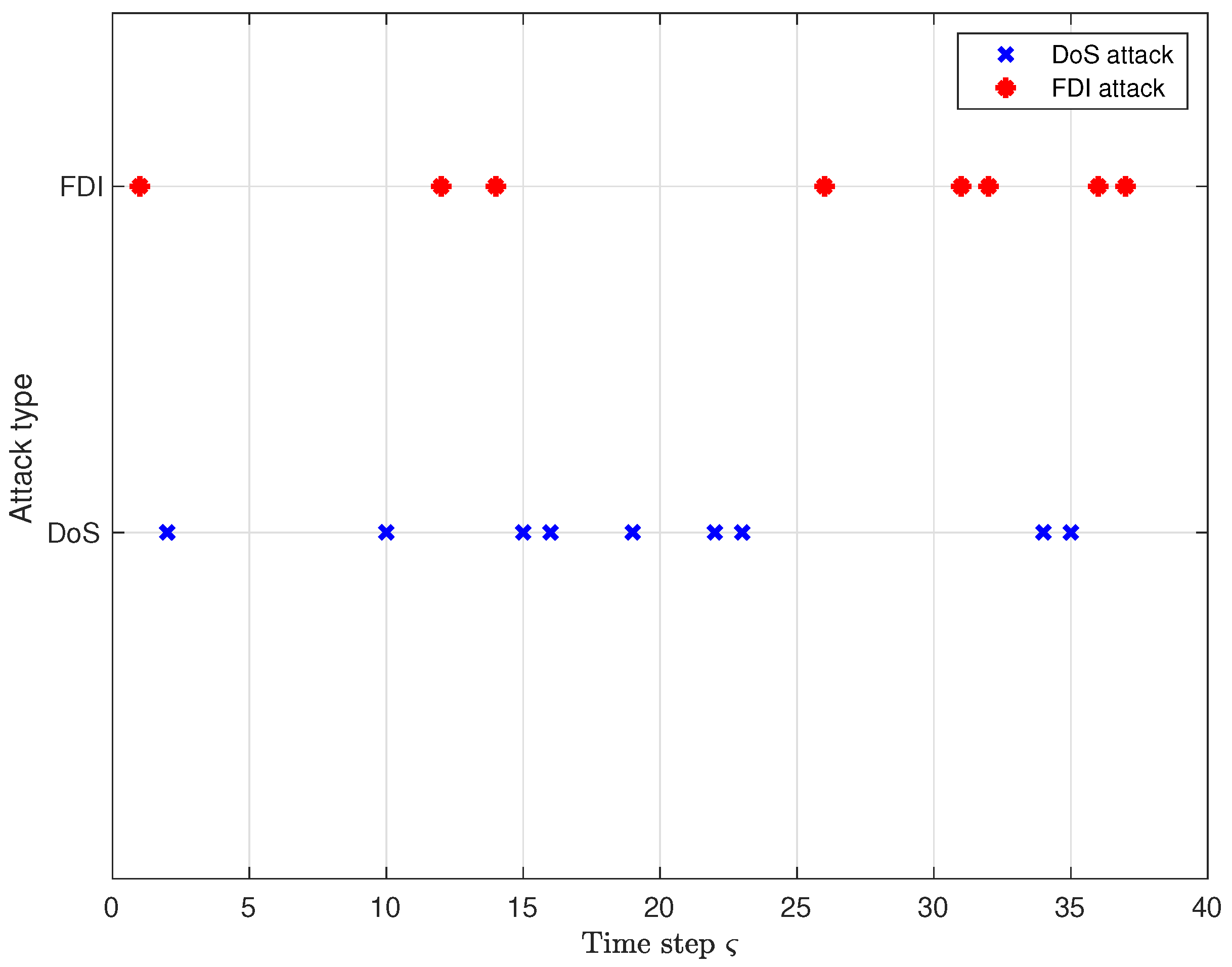
The time instants at which the DoS attack and the FDI attack take place are given in Figure 2, and they occur with probabilities ν ¯ = 0.2 and η ¯ = 0.3 , respectively.
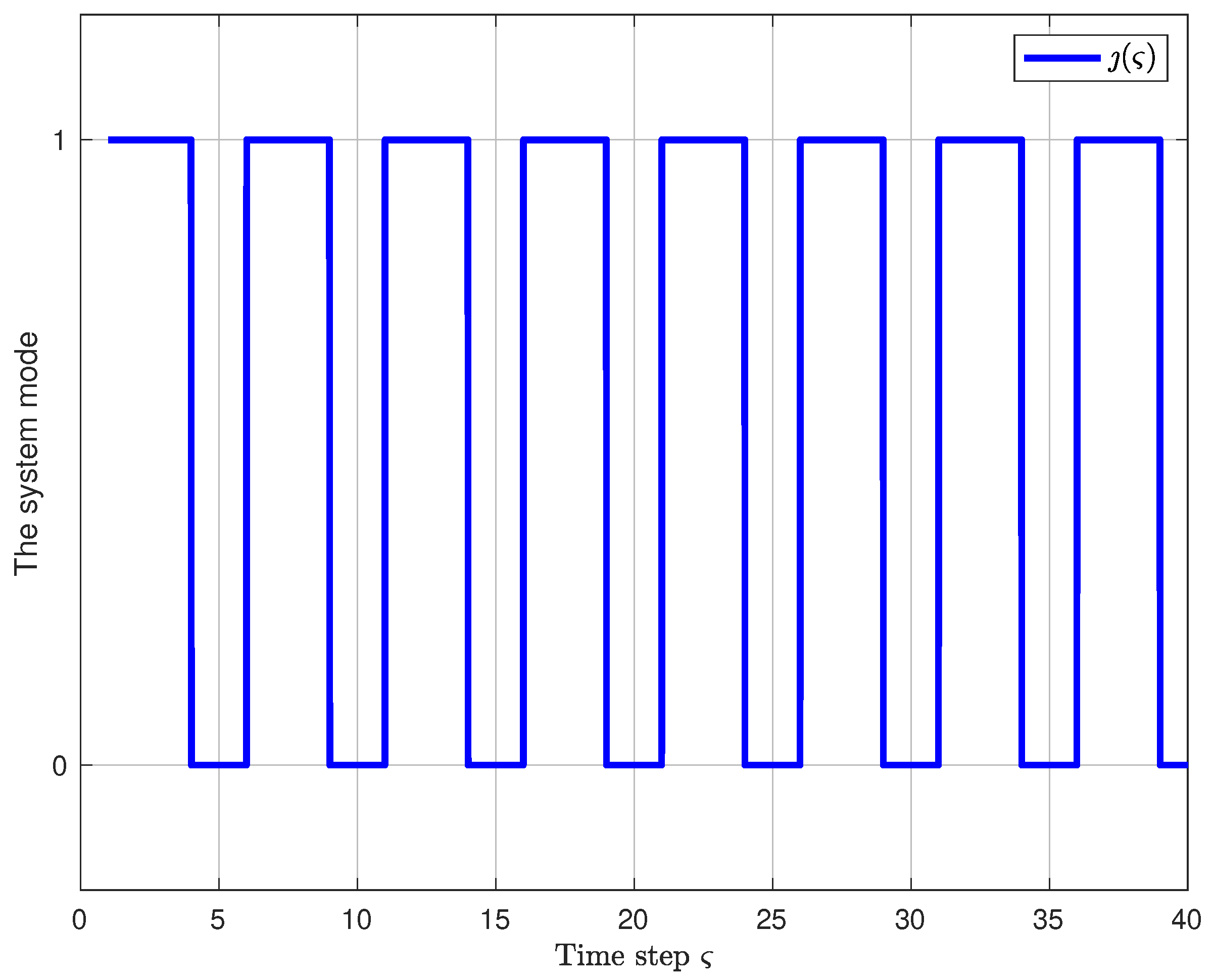
The initial values are ( 1 ) = 2 0.1 1 0.3 0.5 T and P ȷ ( ς ) 1 ( 1 ) = P ȷ ( ς ) 2 ( 1 ) = 0.1 I 5 . Choose λ = 0.97 , μ = 1.04 , γ = 1.1 . On the basis of Theorem 2, τ a d t * = ln μ ln λ = 1.2876 . Therefore, there is τ a d t = 2.5 . Meanwhile, the switching signal ȷ ( ς ) is presented in Figure 3. Furthermore, the controller gains for two modes can be obtained and are presented in Table A1 and Table A2 in Appendix A, where the controller gain K 1 for the system in the RRP mode is given in Table A1 and the controller gain K 0 for the system in the TODP mode is given in Table A2.
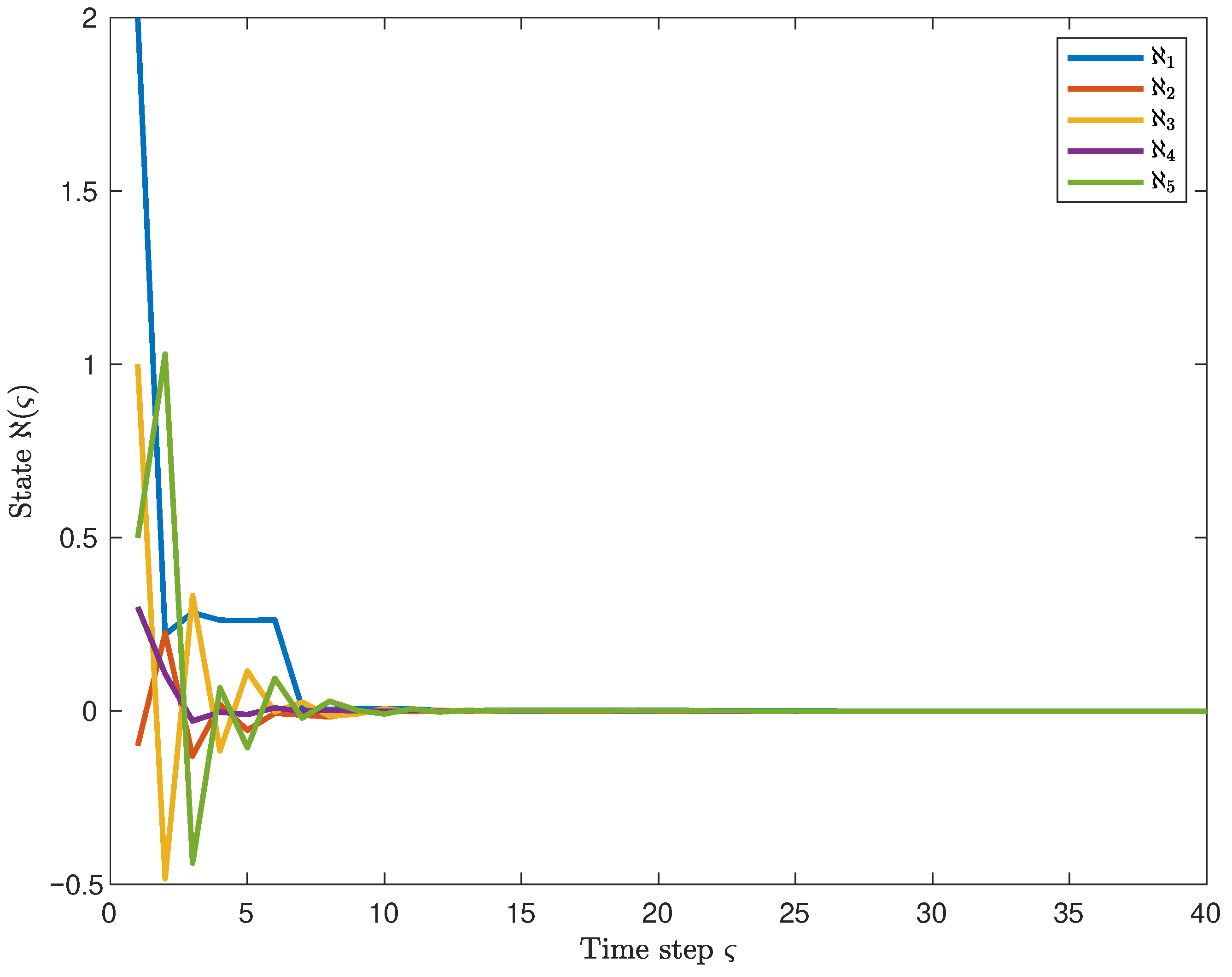
Moreover, Figure 4 shows the state response curves of the system, and one can observe that the state trajectories converge to 0, thereby demonstrating the MSES of the system. Furthermore, the corresponding control output curve is presented in Figure 5. In conjunction with the above, it is apparent that the system output satisfies the given H performance index bound. It indicates that the system maintains good robustness under the influence of ROCAs.
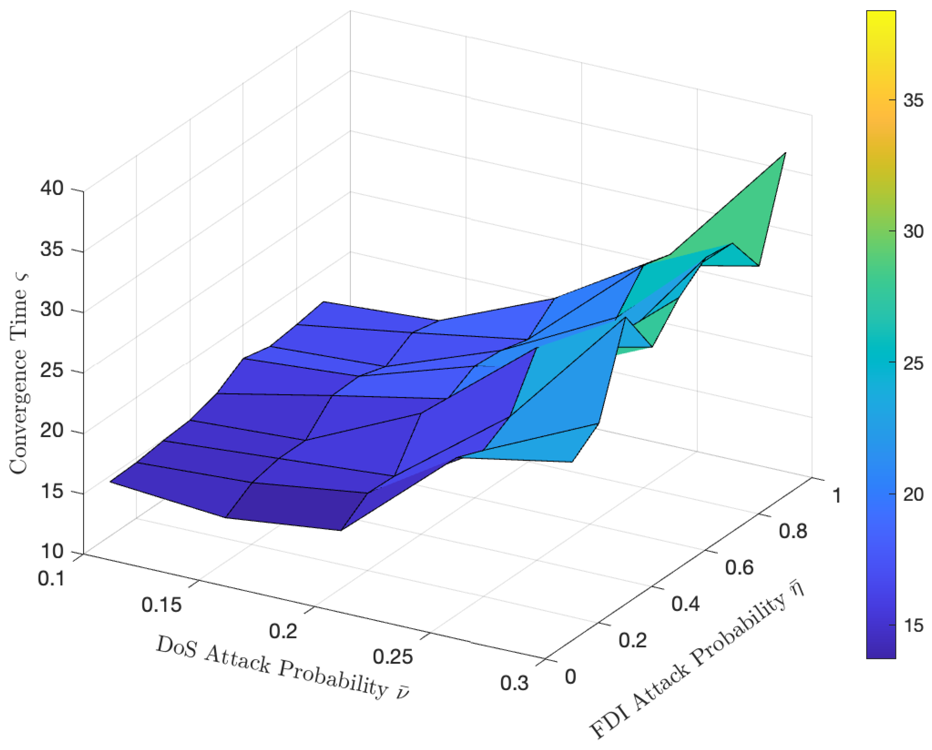
The sensitivity analysis of the probability of DoS and FDI attacks is conducted in Figure 6, of which the convergence time serves as a key performance metric reflecting the stability margin of the system. In the simulation, the convergence time of the system is taken as the average of the experimental results, which is obtained by performing ten trials and calculating the mean. As observed in Figure 6, the system exhibits a significantly higher sensitivity to DoS attacks than to FDI attacks. The convergence time remains short and relatively constant for DoS probabilities between 0 and 0.2, indicating a high stability margin and strong robustness within this range. A critical tipping point is identified at a DoS probability of approximately 0.2. Beyond this threshold, the stability margin decreases rapidly, resulting in a sharp increase in the convergence time. This highlights the critical importance of keeping the DoS attack probability below this value to maintain system resilience.

5. Discussion

Based on the above analysis and results, several possible directions for future research are highlighted and discussed below:
  • Due to the possible switching signal detection delays, which may lead to controller mismatches within each switching interval [57], a natural extension of this work is to consider asynchronous switching between subsystems and their corresponding controllers. Such asynchrony commonly arises in practical NCSs, and studying its impact on stability and performance will be an interesting topic for our future research.
  • In addition, other network-induced phenomena (such as time delay) and actuator saturation are typical phenomena in NCSs. Several recent studies [49,58] have incorporated H performance, time delays, and actuator saturation into the system stability analysis. These factors are not considered in the FRP-based system in our paper. Extending the current results to other systems, such as multi-agent systems [59], and investigating the impact of these factors on the system stability will be important directions for future research.
  • Another possible research direction is to consider more complex cyber attack models, such as those with time-varying or uncertain attack probabilities. Some studies, such as [60], have modeled cyber attacks to better capture the randomness and uncertainty of attack occurrences. Although this paper assumes a fixed attack probability, incorporating uncertainty modeling to further evaluate the robustness of the control strategy under different attack conditions could better capture the dynamic attack patterns that may arise in real-world scenarios. This direction will be further explored in our future research.

6. Conclusions

The problem of the stability and H performance for the FRP-based NCSs subjected to ROCAs is investigated in this paper. Additionally, a novel mathematical model of the system with the FRP is constructed, taking into account the effects of ROCAs. Moreover, a mode-dependent output feedback controller is designed, as well as sufficient conditions for achieving MSES of the system and satisfying the H performance are obtained building on the Lyapunov stability theory, and an algorithm for solving the mode-dependent controller gains is proposed. In the end, a simulation example shows the effectiveness and practicality of the algorithm in addressing the challenges of ROCAs. The system demonstrates good robustness and H performance in the presence of ROCAs. Future research directions include: (1) extending our findings from synchronous switching to asynchronous switching; (2) generalizing the proposed algorithm for use in other systems and considering other network-induced phenomena within the framework of stability analysis; (3) adopting more complex modeling frameworks to better characterize the dynamics of cyber attacks.

Author Contributions

Conceptualization, Y.S.; methodology, Y.S.; software, Y.S.; formal analysis, Y.S. and M.H.; investigation, Y.S. and M.H.; writing—original draft, Y.S.; writing—review and editing, Y.S. and M.H. All authors have read and agreed to the published version of the manuscript.

Funding

This research received no external funding.

Data Availability Statement

The original contributions presented in this study are included in the article. Further inquiries can be directed to the corresponding author.

Conflicts of Interest

The authors declare no conflicts of interest.

Abbreviations

The following abbreviations are used in this manuscript:
MSESMean Square Exponential Stability
NCSsNetworked Control Systems
FRPFlexRay Protocol
ROCAsRandomly Occurring Cyber Attacks
FDIFalse Data Injection
DoSDenial-of-service
ADTAverage Dwell Time
RLMIsRecursive Linear Matrix Inequalities
TODPTry-once-discard Protocol
RRPRound-robin Protocol
SCPStochastic Communication Protocol
CIAConfidentiality, Integrity and Availability
NITNetwork Idle Time

Appendix A. Controller Gain Kȷ(ς)(ς) for Two Modes

Table A1. Controller gain K ȷ ( ς ) ( ς ) with ȷ ( ς ) = 1 .
ς K 1 ( ς )
ς = 1 3.1945 0.2185 0.4025 0.0081 0.0651 4.2431 0.0416 0.0180 0.0032 0.0252 3.5491 0.0131 0.0491 0.0003 0.0421 0.0130 0.0008 0.0030 0.0001 0.0011 0.0182 0.0043 0.0167 0.0004 0.0043
ς = 2 0.0350 0.7700 0.0368 0.0158 0.1537 7.9544 12.0648 1.5599 0.1902 2.4276 0.1030 1.0431 0.0245 0.0185 0.1744 0.1190 0.1658 0.0200 0.0009 0.0101 0.2318 0.4128 0.0417 0.0026 0.0276
ς = 3 0.0335 0.0377 0.2504 0.0385 0.2842 7.7155 1.9789 80.1211 0.2721 1.1246 1.7383 2.8430 13.9467 1.6078 15.7189 0.0747 0.0519 4.6110 0.0564 0.7378 0.3092 0.1558 9.4274 0.1336 1.5999
Table A2. Controller gain K ȷ ( ς ) ( ς ) with ȷ ( ς ) = 0 .
ς K 0 ( ς )
ς = 4 0.0017 0.0111 0.0159 0.0037 0.1649 0.1972 0.0533 0.1396 0.1453 1.7322 0.2124 0.1245 0.2323 0.1063 1.8862 0.0069 0.1451 0.3370 0.0469 0.0960 0.3224 0.1291 0.5867 0.0792 1.0865
ς = 5 0.0037 0.0246 0.0407 0.0028 0.2873 0.2673 0.0729 0.1830 0.0947 2.1279 0.3542 0.1735 0.3446 0.0874 2.7321 0.0653 0.1349 0.3282 0.0389 0.0872 0.6693 0.2096 0.8067 0.0628 1.5720

References

  1. Hu, J.; Zhang, H.; Liu, H.; Yu, X. A survey on sliding mode control for networked control systems. Int. J. Syst. Sci. 2021, 52, 1129–1147. [Google Scholar] [CrossRef]
  2. Zhang, X.M.; Han, Q.L.; Ge, X.; Ding, D.; Ding, L.; Yue, D.; Peng, C. Networked control systems: A survey of trends and techniques. IEEE/CAA J. Autom. Sin. 2020, 7, 1–17. [Google Scholar] [CrossRef]
  3. Fu, A.; McCann, J.A. Dynamic decentralized periodic event-triggered control for wireless cyber–physical systems. IEEE Trans. Control Syst. Technol. 2021, 29, 1783–1790. [Google Scholar] [CrossRef]
  4. Aslam, M.S.; Tiwari, P.; Pandey, H.M.; Band, S.S. Observer–based control for a new stochastic maximum power point tracking for photovoltaic systems with networked control system. IEEE Trans. Fuzzy Syst. 2023, 31, 1870–1884. [Google Scholar] [CrossRef]
  5. Zhang, D.; Han, Q.L.; Zhang, X.M. Network-based modeling and proportional–integral control for direct-drive-wheel systems in wireless network environments. IEEE Trans. Cybern. 2020, 50, 2462–2474. [Google Scholar] [CrossRef]
  6. Li, X.; Feng, S.; Hou, N.; Wang, R.; Li, H.; Gao, M.; Li, S. Surface microseismic data denoising based on sparse autoencoder and Kalman filter. Syst. Sci. Control Eng. 2022, 10, 616–628. [Google Scholar] [CrossRef]
  7. Wu, C.; Zhao, X.; Li, C.; Zhao, N. Controller synthesis of asynchronous periodic event-triggered networked control systems subject to quantization effects. IEEE Trans. Signal Inf. Process. Netw. 2022, 8, 907–919. [Google Scholar] [CrossRef]
  8. Zhang, X.M.; Han, Q.L.; Ge, X. A novel approach to H performance analysis of discrete-time networked systems subject to network-induced delays and malicious packet dropouts. Automatica 2022, 136, 110010. [Google Scholar] [CrossRef]
  9. Li, C.; Zhao, X.; Chen, M.; Xing, W.; Zhao, N.; Zong, G. Dynamic periodic event-triggered control for networked control systems under packet dropouts. IEEE Trans. Autom. Sci. Eng. 2024, 21, 906–920. [Google Scholar] [CrossRef]
  10. Liu, J.; Wu, Z.G.; Yue, D.; Park, J.H. Stabilization of networked control systems with hybrid-driven mechanism and probabilistic cyber attacks. IEEE Trans. Syst. Man Cybern. Syst. 2021, 51, 943–953. [Google Scholar] [CrossRef]
  11. Li, Z.M.; Chang, X.H.; Xiong, J. Event-based fuzzy tracking control for nonlinear networked systems subject to dynamic quantization. IEEE Trans. Fuzzy Syst. 2023, 31, 941–954. [Google Scholar] [CrossRef]
  12. Liang, G.; Weller, S.R.; Zhao, J.; Luo, F.; Dong, Z.Y. The 2015 Ukraine blackout: Implications for false data injection attacks. IEEE Trans. Power Syst. 2017, 32, 3317–3318. [Google Scholar] [CrossRef]
  13. Pang, Z.H.; Fan, L.Z.; Guo, H.; Shi, Y.; Chai, R.; Sun, J.; Liu, G.P. Security of networked control systems subject to deception attacks: A survey. Int. J. Syst. Sci. 2022, 53, 3577–3598. [Google Scholar] [CrossRef]
  14. Li, H.; Yang, Q.; Zhan, X.; Wu, J.; Yan, H. Hybrid-triggered H control for networked control systems with deception attacks. IEEE Trans. Circuits Syst. II Exp. Briefs 2023, 70, 3494–3498. [Google Scholar] [CrossRef]
  15. Mahmoud, M.S.; Hamdan, M.M.; Baroudi, U.A. Secure control of cyber physical systems subject to stochastic distributed DoS and deception attacks. Int. J. Syst. Sci. 2020, 51, 1653–1668. [Google Scholar] [CrossRef]
  16. Zhang, L.; Sun, S. Distributed H fusion filtering for multi-sensor networked systems with DoS attacks and sensor saturations. Digit. Signal Process. 2023, 134, 103908. [Google Scholar] [CrossRef]
  17. Liu, J.; Ke, J.; Liu, J.; Xie, X.; Tian, E. Secure event-triggered control for IT-2 fuzzy networked systems with stochastic communication protocol and FDI attacks. IEEE Trans. Fuzzy Syst. 2024, 32, 1167–1180. [Google Scholar] [CrossRef]
  18. Pang, Z.H.; Fan, L.Z.; Dong, Z.; Han, Q.L.; Liu, G.P. False data injection attacks against partial sensor measurements of networked control systems. IEEE Trans. Circuits Syst. II Exp. Briefs 2022, 69, 149–153. [Google Scholar] [CrossRef]
  19. Yan, H.; Wang, J.; Zhang, H.; Shen, H.; Zhan, X. Event-based security control for stochastic networked systems subject to attacks. IEEE Trans. Syst. Man Cybern. Syst. 2020, 50, 4643–4654. [Google Scholar] [CrossRef]
  20. Liu, J.; Wang, S.; Hu, B.; Liu, J.; Xie, X.; Tian, E. Non-fragile observer-based security control for networked systems via event-triggered WTOD protocol. Int. J. Robust Nonlinear Control 2024, 34, 5852–5872. [Google Scholar] [CrossRef]
  21. Wang, F.; Liang, J.; Lam, J.; Yang, J.; Zhao, C. Robust filtering for 2-D systems with uncertain-variance noises and weighted try-once-discard protocols. IEEE Trans. Syst. Man Cybern. Syst. 2023, 53, 2914–2924. [Google Scholar] [CrossRef]
  22. Li, Y.; Song, F.; Liu, J.; Xie, X.; Tian, E.; Fei, S. Round Robin-based synchronization control for discrete-time complex networks with probabilistic coupling delay and deception attacks. IEEE Trans. Syst. Man Cybern Syst. 2024, 54, 4425–4436. [Google Scholar] [CrossRef]
  23. Shang, H.; Zong, G.; Qi, W. Security control for networked discrete-time semi-Markov jump systems with round-robin protocol. IEEE Trans. Circuits Syst. II Exp. Briefs 2022, 69, 2812–2816. [Google Scholar] [CrossRef]
  24. Liu, J.; Ke, J.; Liu, J.; Xie, X.; Tian, E. Stochastic communication protocol-based security control for discrete-time networked systems using state observer. IEEE Trans. Syst. Man Cybern Syst. 2024, 54, 5501–5512. [Google Scholar] [CrossRef]
  25. Cheng, J.; Zhang, Q.; Yan, H.; Zhang, D.; Park, J.H. Observer-based sliding mode control for fuzzy systems under stochastic communication protocol. IEEE Trans. Circuits Syst. II 2024, 71, 3860–3864. [Google Scholar] [CrossRef]
  26. Liu, S.; Wang, Z.; Wang, L.; Wei, G. Recursive set-membership state estimation over a FlexRay network. IEEE Trans. Syst. Man Cybern. Syst. 2022, 52, 3591–3601. [Google Scholar] [CrossRef]
  27. Wang, W.; Nešić, D.; Postoyan, R. Emulation-based stabilization of networked control systems implemented on FlexRay. Automatica 2015, 59, 73–83. [Google Scholar] [CrossRef]
  28. Tang, Y.; Zhang, D.; Ho, D.W.C.; Qian, F. Tracking control of a class of cyber-physical systems via a FlexRay communication network. IEEE Trans. Cybern. 2019, 49, 1186–1199. [Google Scholar] [CrossRef]
  29. Liu, S.; Wang, Z.; Wang, L.; Wei, G. Finite-horizon H filtering via a high-rate network with the FlexRay protocol. IEEE Trans. Autom. Control 2023, 68, 3596–3603. [Google Scholar] [CrossRef]
  30. Wang, Y.; Wang, Z.; Zou, L.; Ma, L.; Dong, H. Ultimately bounded PID control for T–S fuzzy systems under FlexRay communication protocol. IEEE Trans. Fuzzy Syst. 2023, 31, 4308–4320. [Google Scholar] [CrossRef]
  31. Liu, J.; Wang, S.; Liu, J.; Xie, X.; Tian, E. FlexRay protocol-based event-triggered secure filtering for IT-2 fuzzy systems with fading measurements over high-rate communication networks: The finite-horizon case. IEEE Trans. Syst. Man Cybern Syst. 2024, 54, 6055–6067. [Google Scholar] [CrossRef]
  32. Wang, W.; Nešić, D.; Postoyan, R. Observer design for networked control systems with FlexRay. Automatica 2017, 82, 42–48. [Google Scholar] [CrossRef]
  33. Zhu, Y.; Tang, X.; Kang, D.; Zhang, L.; She, M.; Tan, C. Static output feedback H2/H fault-tolerant control for nonlinear networked systems under hybrid cyber attacks and hybrid-triggered mechanisms. Int. J. Control Autom. Syst. 2025, 23, 1722–1735. [Google Scholar] [CrossRef]
  34. Hu, Y.; Kwon, O.M.; Lee, S.H. H control for interval type-2 fuzzy singularly perturbed systems with multi-node round-robin protocol and packet dropouts. Fuzzy Sets Syst. 2025, 500, 109202. [Google Scholar] [CrossRef]
  35. Wu, Z.; Wang, Y.; Xiong, J.; Xie, M. Switching periodic event-triggered H control for NCSs and its application to UAVs. IEEE Trans. Veh. Technol. 2024, 73, 5078–5088. [Google Scholar] [CrossRef]
  36. Zhi, Y.; Liu, X.; He, S.; Lin, W.; Chen, W. Adaptively event-triggered H control for networked autonomous aerial vehicles control systems under deception attacks. IEEE Trans. Ind. Inform. 2025, 21, 3458–3465. [Google Scholar] [CrossRef]
  37. Yue, D.; Tian, E.; Han, Q.L. A delay system method for designing event-triggered controllers of networked control systems. IEEE Trans. Autom. Control 2013, 58, 475–481. [Google Scholar] [CrossRef]
  38. Tan, Y.; Liu, J.; Xie, X.; Tian, E.; Liu, J. Dynamic-memory event-triggered sliding-mode secure control for nonlinear semi-Markov jump systems with stochastic cyber attacks. IEEE Trans. Autom. Sci. Eng. 2025, 22, 202–214. [Google Scholar] [CrossRef]
  39. Zhong, Q.; Yang, J.; Shi, K.; Zhong, S. Design of observer-based discrete-type PID control for reconstructed jump model of interconnected power system under hybrid attacks. IEEE Trans. Smart Grid 2023, 14, 1896–1906. [Google Scholar] [CrossRef]
  40. Cheng, J.; Pang, H.; Yan, H.; Zhang, D. Protocol-based PID control of switched systems with DoS attacks. IEEE Trans. Inf. Forensics Secur. 2025, 20, 8059–8068. [Google Scholar] [CrossRef]
  41. Gao, X.; Deng, F.; Zeng, P.; Liu, X. Protocol-based stability analysis of stochastic hybrid systems under DoS attacks. IEEE Trans. Syst. Man Cybern. Syst. 2022, 52, 6348–6358. [Google Scholar] [CrossRef]
  42. Yang, H.; Peng, C.; Cao, Z. Attack-model-independent stabilization of networked control systems under a jump-like TOD scheduling protocol. Automatica 2023, 152, 110982. [Google Scholar] [CrossRef]
  43. Yu, T.; Xu, H.; He, S. GA-optimized co-design of jump-like FlexRay protocol and dynamic control for NCSs and its applications. IEEE Syst. J. 2025, 19, 670–681. [Google Scholar] [CrossRef]
  44. Hu, J.; Yang, S.; Caballero-Águila, R.; Dong, H.; Wu, B. Mixed static-dynamic protocol-based Tobit recursive filtering for stochastic nonlinear systems against random false data injection attacks. IEEE Trans. Signal Inf. Process. Netw. 2024, 10, 445–459. [Google Scholar] [CrossRef]
  45. Liu, S.; Wei, G.; Song, Y.; Liu, Y. Extended Kalman filtering for stochastic nonlinear systems with randomly occurring cyber attacks. Neurocomputing 2016, 207, 708–716. [Google Scholar] [CrossRef]
  46. Song, H.; Ding, D.; Dong, H.; Yi, X. Distributed filtering based on Cauchy-kernel-based maximum correntropy subject to randomly occurring cyber-attacks. Automatica 2022, 135, 110004. [Google Scholar] [CrossRef]
  47. Zhang, P.; Zhu, C.; Wang, Z.; Yang, B. Recursive set-membership filtering for two-dimensional shift-varying systems with FlexRay protocol and hybrid cyber attacks. Asian J. Control 2025, 27, 797–816. [Google Scholar] [CrossRef]
  48. Qu, F.; Tian, E.; Zhao, X. Chance-constrained H state estimation for recursive neural networks under deception attacks and energy constraints: The finite-horizon case. IEEE Trans. Neural Netw. Learn. Syst. 2023, 34, 6492–6503. [Google Scholar] [CrossRef]
  49. Zhi, Y.L.; Liu, X.; Wang, Y.; Fan, Y. Network-based H control for descriptor systems with time delays under a novel event-triggered strategy. IEEE Trans. Control Netw. Syst. 2025, 12, 943–953. [Google Scholar] [CrossRef]
  50. Xu, Y.; Mu, X.; Cheng, G. Event-triggered H control for switched systems under multiple attacks. Int. J. Control Autom. Syst. 2023, 21, 1089–1097. [Google Scholar] [CrossRef]
  51. Qi, W.; Zhang, N.; Ahn, C.K.; Zong, G. Genetic-algorithm-based sliding-mode stabilization for networked switched systems with unreliable channels. IEEE Trans. Control Netw. Syst. 2024, 11, 1778–1789. [Google Scholar] [CrossRef]
  52. Hespanha, J.P.; Morse, A.S. Stability of switched systems with average dwell-time. In Proceedings of the 38th IEEE Conference on Decision and Control, Phoenix, AZ, USA, 7–10 December 1999. [Google Scholar]
  53. Deng, Y.; Zhang, H.; Xia, J. H control with convergence rate constraint for time-varying delay switched systems. IEEE Trans. Syst. Man Cybern. Syst. 2023, 53, 7354–7363. [Google Scholar] [CrossRef]
  54. Zhang, D.; Xu, Z.; Karimi, H.R.; Wang, Q. Distributed filtering for switched linear systems with sensor networks in presence of packet dropouts and quantization. IEEE Trans. Circuits Syst. I Reg. Pap. 2017, 64, 2783–2796. [Google Scholar] [CrossRef]
  55. Daafouz, J.; Riedinger, P.; Iung, C. Stability analysis and control synthesis for switched systems: A switched Lyapunov function approach. IEEE Trans. Autom. Control 2002, 47, 1883–1887. [Google Scholar] [CrossRef]
  56. Huang, K.; Pan, F. Finite horizon H-infinity control of nonlinear time-varying systems under WTOD protocol. IEEE Access 2022, 10, 20400–20406. [Google Scholar] [CrossRef]
  57. Wang, Z.; He, W.; Sun, J.; Wang, G.; Chen, J. Event-triggered control of switched nonlinear time-delay systems with asynchronous switching. IEEE Trans. Cybern. 2024, 54, 4348–4358. [Google Scholar] [CrossRef]
  58. Huang, X.; Xing, M.; Mo, H.; Hu, S.; Luo, H. Stabilization of uncertain networked control systems with actuator saturation and probabilistic cyberattacks. Asian J. Control 2023, 25, 1407–1419. [Google Scholar] [CrossRef]
  59. Liu, J.; Yin, T.; Yue, D.; Karimi, H.R.; Cao, J. Event-based secure leader-following consensus control for multiagent systems with multiple cyber attacks. IEEE Trans. Cybern. 2021, 51, 162–173. [Google Scholar] [CrossRef]
  60. Ma, Y.; Li, Z. Neural network-based secure event-triggered control of uncertain industrial cyber-physical systems against deception attacks. Inf. Sci. 2023, 633, 504–516. [Google Scholar] [CrossRef]
Figure 1. Main blocks with the FRP and ROCAs.(a) Framework of NCSs with communication network. (b) Schematic diagram of a communication cycle of the FRP. (c) FRP-based communication network under ROCAs.
Mathematics 13 03515 g001
Figure 2. The occurrence time of the DoS attack and FDI attack.
Mathematics 13 03515 g002
Figure 3. Switching signal ȷ ( ς ) with the ADT of 2.5 (“1” represents the RRP mode and “0” represents the TODP mode).
Mathematics 13 03515 g003
Figure 4. Response curve of system state ( ς ) with exogenous disturbance N ( ς ) 0 (as shown in (47)).
Mathematics 13 03515 g004
Figure 5. Response curve of controller output O ( ς ) with exogenous disturbance N ( ς ) 0 (as shown in (47)).
Mathematics 13 03515 g005
Figure 6. Sensitivity analysis.
Mathematics 13 03515 g006
Table 1. The notations of key variables and subscripts.
SymbolImplication
ς time instant
ȷ ( ς ) a switching signal between the static segment and the dynamic segment
σ ς the sensor node granted network access at time instnat ς under RRP
ξ ς the sensor node granted network access at time instnat ς under TODP
ν ς a Bernoulli variable that denotes whether a DoS attack occurs
η ς a Bernoulli variable that denotes whether a FDI attack occurs
Φ σ ς an auxiliary matrix in RRP
Ω ξ ς an auxiliary matrix in TODP
Θ ȷ ( ς ) ( ς ) a mode-dependent variable with respect to auxiliary matrices
I ¯ ȷ ( ς ) a mode-dependent variable with respect to identify matrices
A ¯ ȷ ( ς ) ( ς ) a time-varying matrix with appropriate dimensions in the corresponding subsystem
Disclaimer/Publisher’s Note: The statements, opinions and data contained in all publications are solely those of the individual author(s) and contributor(s) and not of MDPI and/or the editor(s). MDPI and/or the editor(s) disclaim responsibility for any injury to people or property resulting from any ideas, methods, instructions or products referred to in the content.