Article

Wave Scattering and Trapping by C-Type Floating Breakwaters in the Presence of Bottom-Standing Perforated Semicircular Humps

1
State Key Laboratory of Coastal and Offshore Engineering, Dalian University of Technology, Dalian 116024, China
2
Department of Mathematics, SRM Institute of Science and Technology, Chennai 603203, India
3
Center of Excellence for Ocean Engineering, National Taiwan Ocean University, Keelung 202301, Taiwan
*
Author to whom correspondence should be addressed.
Mathematics 2025, 13(21), 3372; https://doi.org/10.3390/math13213372
Submission received: 12 September 2025 / Revised: 8 October 2025 / Accepted: 17 October 2025 / Published: 23 October 2025
(This article belongs to the Section E: Applied Mathematics)

Abstract

In this paper, the propagation of surface gravity waves over multiple bottom-standing porous semicircular humps is examined in the absence and presence of double floating C -type detached asymmetric breakwaters. Both wave scattering and trapping phenomena are investigated within the framework of small-amplitude linear water wave theory, with the governing problem numerically solved using the multi-domain Boundary Element Method (BEM) in finite-depth water. A detailed parametric analysis is conducted to evaluate the effects of key physical parameters, including hump radius, porosity, spacing between adjacent humps, and the separation between the two C -type detached breakwaters. The study presents results for reflection and transmission coefficients, free-surface elevations, and the horizontal and vertical forces acting on the first perforated semicircular hump, as well as on the shore-fixed wall. The findings highlight the significant role of porous humps in altering Bragg scattering characteristics. For larger wavenumbers, wave reflection increases notably in the presence of a vertical shore-fixed wall, while it tends to vanish in its absence. Reflection is also observed to decrease with an increase in semicircle radius. Furthermore, as the wavenumber approaches zero, the vertical force on multiple permeable semicircles converges to zero, whereas for impermeable semicircles, it approaches unity. In addition, the horizontal force acting on the shore-fixed wall diminishes rapidly with increasing porosity of the semicircular humps.

1. Introduction

The study of how surface gravity waves transform when propagating over periodically varying seabed profiles is of great importance, as it provides insight into several coastal phenomena such as resonance, shoaling, refraction, and reflection. Resonance effects are strongest when the wavelength of the incident wave is exactly twice that of the seabed undulation, a condition widely known in solid-state physics as Bragg resonance. In recent years, seabed modifications have been increasingly adopted as cost-efficient solutions for reducing wave forces in the marine environment. Among these, submerged porous humps, artificial reefs, and breakwaters have been designed and implemented as effective coastal protection systems.
Seabed-mounted submerged humps are significant as alternatives to floating structures. Compared with floating barriers, submerged humps produce lower ecological and visual impacts and are less exposed to damage from intense wave breaking. These advantages make them promising candidates for shoreline protection and for advancing marine renewable energy projects. Consequently, numerous studies have been dedicated to analyzing wave–structure interactions involving submerged seabed humps (see Mei and Black [1], Porter [2], and Xie et al. [3]). Liu et al. [4] investigated the scattering of surface waves by a series of submerged rigid semicircular breakwaters using the multipole expansion method. Their results showed that the maximum Bragg reflection coefficient increased with the number of barriers, while the corresponding bandwidth decreased. Ding et al. [5] examined the modified Bragg’s law and provided its quantitative expression for water wave resonances produced by five kinds of artificial bars. Akarni et al. [6] performed numerical simulations to study how waves interact with submerged structures in a uniform flow current. The results indicated that wave attenuation was greater when the current flowed in the same direction as the waves and was reduced when the current flowed opposite to the wave direction. Recently, Goyal et al. [7] studied the optimal arrangement of multiple rigid bars with different drafts to maximize Bragg reflection of surface gravity waves. Anilkumar and Panduranga [8] studied how submerged twin-wing breakwaters help generate calm wave conditions in harbor regions.
Apart from the wave scattering by submerged bottom-standing rigid breakwaters or humps, porous and perforated seabed structures are also widely applied in coastal and offshore engineering. A notable example is the semicircular caisson breakwater (see Teng et al. [9], Dhinakaran et al. [10], and Liu et al. [11]). Koley and Sahoo [12] examined the interaction of waves with a submerged semicircular perforated breakwater positioned on a porous seabed. Li et al. [13] conducted analytical and experimental investigations on Bragg scattering of water waves by multiple submerged perforated semicircular breakwaters. Sharma et al. [14] examined the wave interaction with a submerged floating tunnel situated alongside a bottom-mounted porous breakwater. Khan and Behera [15] developed a numerical model based on the BEM to analyze wave propagation through multiple submerged porous barriers. Li et al. [16] investigated the behavior of surface gravity waves as they interact with multiple submerged porous reef balls. Vijay et al. [17] explored how gravity waves scatter when interacting with arrays of porous and non-porous breakwaters arranged in two ways: (i) beneath a floating dock and (ii) at some distance from it. They found that rectangular breakwaters placed at a finite distance from the dock were more effective in reducing incident wave energy than those installed directly below. More recently, Ni and Teng [18] focused on the behavior of surface gravity waves over porous multiple trapezoidal seabed-mounted bars placed on a porous sloping bed. The analytical and numerical modeling of porous and perforated breakwaters based on potential flow theory was reviewed by Han and Wang [19]. An experimental study on the hydrodynamic characteristics of an offshore seabed-fixed cylinder with truncated porous shells was conducted by Pan et al. [20]. Venkateswarlu et al. [21] investigated the wave-structure interaction of a quarter-circular breakwater equipped with four different types of porous shields, using small-amplitude wave theory. Their findings indicated that, compared to a standalone quarter-circular breakwater at wavenumber k 0 h = 1 , the wave transmission was reduced by approximately 39 % , 30 % , 31 % , and 56 % for the four types of porous shields, respectively. Very recently, Sahoo et al. [22] investigated the scattering of water waves in the presence of multiple bottom-standing porous structures and a floating elastic plate analytically using the Eigenfunction Expansion Method (EEM). The study revealed that a configuration with four perforated structures may have the capacity to damp nearly 65 % of incident waves.
There is a growing interest in creating a calm area near ports and coasts by trapping waves with the structures placed at a finite distance from a fixed rigid sea wall (Penney et al. [23]). Chang and Tsai [24] investigated the hydrodynamic forces exerted on a partially reflecting seawall due to oblique Bragg scattering in the presence of multiple porous rectangular or trapezoidal breakwaters. Halvorson and Huang [25] analyzed the effects of perforation layouts on wave energy dissipation caused by a submerged perforated breakwater in front of a vertical seawall. Swami and Koley [26] examined wave trapping mechanisms induced by a porous breakwater positioned near a rigid wall under the influence of background ocean currents. Dora et al. [27] examined the phenomenon of wave trapping caused by a porous breakwater located close to a wall, taking into account the effects of an ocean current. Despite these contributions, studies specifically focusing on the effects of the modified porous parameter on wave trapping and scattering, particularly in systems involving multiple perforated semicircular seabed-mounted structures combined with double floating detached C -type asymmetric breakwaters, remain absent in the literature.
In some of the aforementioned studies, the BEM has been employed due to its efficiency and accuracy in solving wave–structure interaction problems (Khan and Behera [15], Ni and Teng [18], Matsui et al. [28]). One of the key advantages of the BEM is that it eliminates the need to explicitly solve the complex dispersion relation, since the governing equations are formulated directly on the boundary of the computational domain. The primary advantage of the Boundary Element Method (BEM) over CFD-based approaches lies in its computational efficiency. In the BEM, only the boundaries of the domain are discretized, whereas CFD methods require meshing of the entire fluid volume. Consequently, the BEM significantly reduces computational cost in terms of both memory usage and processing time, making it particularly suitable for linear wave–structure interaction problems. While a large number of investigations have focused on two-dimensional wave–structure interaction problems using the BEM, there also exist several important studies on three-dimensional formulations (e.g., Hess and Smith [29], Matsui et al. [28], Magkouris et al. [30]). In the three-dimensional case, the mathematical formulation requires essential modifications: the fundamental solution of the Laplace equation changes from ln r in 2-D to 1 / ( 4 π r ) in 3-D (Brehhia et al. [31], Sauter and Schwab [32]), boundary integrals must be evaluated over surfaces instead of lines, and reflection/transmission need to be defined in terms of fluxes across control surfaces in all spatial directions (Mei [33], Show et al. [34]). These extensions make the formulation more challenging but also more realistic, enabling deeper insights into practical three-dimensional wave–structure interaction problems. Thus, the authors are motivated to consider the two-dimensional configuration in the present study in order to analyze wave scattering and trapping phenomena in detail. The 2-D framework not only provides valuable physical insights and a clearer understanding of the underlying mechanisms but also offers a reliable basis for validating the methodology before extending the analysis to more complicated three-dimensional problems.
In the present study, a numerical investigation is conducted using the multi-domain BEM to analyze scattering coefficients, including reflection, transmission, and dissipation. The free-surface elevation, the wave forces acting on perforated/imperforate semicircular humps, and horizontal force acting on the shore-fixed wall are calculated. The present study is carried out with the presence and absence of C-type floating double breakwaters. The BEM formulations are based on linearized potential flow theory. The primary objective of the BEM models is to investigate the Bragg resonant behavior of trapping and scattering waves with bottom-standing humps and floating C-type breakwaters in the presence of incoming waves. The present study also examines the modifications in bandwidth and Bragg resonance in the presence of semicircular humps on the scattering coefficients and the shifting of the peak resonant frequency due to different structural and wave parameters. The present results agree well with the existing analytical results available in the published literature. The role of various physical parameters, such as hump radius, porosity, the gap between the adjacent sides of the humps, and the gap between C-type breakwaters, is studied. The reflection and transmission coefficients are plotted to understand the effective role of the perforated semicircular hump on Bragg scattering and trapping.

2. Mathematical Formulation

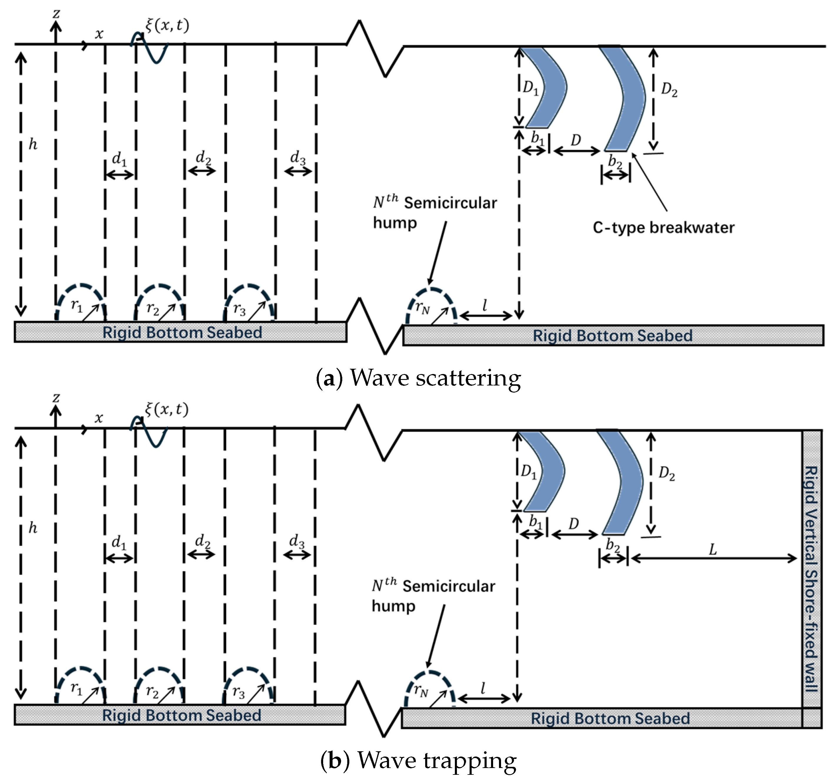
The interaction of surface gravity waves with C-type rigid fixed detached double breakwaters in the presence of multiple bottom-standing porous semicircular humps is investigated in a two-dimensional Cartesian coordinate system. The x-axis is taken along the mean free surface in the horizontal direction, while the z-axis is oriented vertically upward. An array of N porous semicircular humps is considered, where the radius of the jth hump is denoted by r j , and the spacing between the jth and ( j + 1 ) th humps is represented by d j for j = 1 , 2 , 3 , , N 1 . On the free surface ( z = 0 ), two C-type detached breakwaters are placed: the lees-side breakwater with submerged depth D 1 and thickness b 1 , and the sea-side breakwater with submerged depth D 2 and thickness b 2 . The gap length between the two C-type breakwaters is denoted by D, while l represents the spacing between the rightmost semicircular hump and the sea-side breakwater. The water depth in the region outside the array of bottom-standing humps is h, as illustrated in both Figure 1 and Figure 2. Assuming small-amplitude linear wave theory, the motion of the fluid is taken to be simple-harmonic in time with angular frequency ω . The velocity potential in the jth region is expressed as Φ j i ( x , z , t ) = ϕ j i ( x , z ) e i ω t , where the indices ( i , j ) denote different subdomains in the computational domain. Specifically, ( i , j ) = ( 1 , 1 ) corresponds to the open water region, while ( i , j ) = ( 2 , j ) , j = 1 , 2 , , N , represents the porous regions of the jth hump. Thus, the spatial components of the velocity potentials ϕ j i ( x , z ) satisfy the Laplace equation in the fluid interior as
2 x 2 + 2 z 2 ϕ j i = 0 for ( i , j ) , i = 1 , 2 j 1 , 2 , , N .
The free-surface condition on the open water region is given by
ϕ 1 1 n K ϕ 1 1 = 0 , at z = 0 ,
where K = ω 2 / g and n acts as the normal outward to the surface, and g is the acceleration due to gravity. Although the gravitational acceleration g may vary slightly (typically within ±0.5–1%) depending on geographical location and tidal interactions, in the present theoretical formulation, we assume g = 9.81 m/ s 2 as a constant reference value. This assumption has been consistently adopted in many studies over the years (Mei [33], Evans and Linton [35], Linton and McIver [36], Barman et al. [37]). Such minor variations in g would lead only to marginal changes in the progressive wavenumber k 0 and in the parameter K = ω 2 / g and hence do not affect the overall trends or conclusions of the study. As no flux is permitted at the hard horizontal seabed, the surface of rigid breakwaters yields
ϕ j i n = 0 for ( i , j ) , i = 1 , 2 ; j 1 , 2 , , N .
At the interface of the porous semicircular hump and the open water region, the matching boundary conditions (see Yu and Chwang [38]) are given by
ϕ 1 1 n = ϕ j 2 n = i k 0 σ ( ϕ 1 1 ϕ j 2 ) for j = 1 , 2 , , N ,
where σ = ϵ k 0 δ ( f i s ) is the porosity of the humps in which δ is the semicircle thickness, k 0 is the progressive wavenumber, and ϵ , and f and s denote the geometrical porosity, the resistance coefficient and the inertial effect coefficient of the perforated semicircular hump, respectively. The alternative normalized porous effect parameter (see the details in Liu et al. [39]) is
G 0 = h δ ϵ f i s = k 0 σ h .
The far-field wave radiations are described at the reflected and transmitted waveside as follows:
ϕ 1 1 ( x , z ) ϕ i n c 1 ( x , z ) + R 0 ϕ i n c 1 ( x , z ) , for x T 0 ϕ i n c 1 ( x , z ) , for x
where ϕ i n c 1 ( x , z ) = cosh k 0 ( z + h ) cosh k 0 h e i k 0 x is the incident potential, with k 0 being the positive wavenumber corresponding to the progressive wave propagating in the open water region. Here, R 0 and T 0 denote the unknown constants related to the reflected and transmitted waves’ amplitudes, respectively, which will be calculated.

2.1. Methodology: BEM

Applying Green’s second identity to the velocity potential ϕ j i ( x , z ) and the two-dimensional free-space Green’s function G ( x , z ; x 0 , z 0 ) bounded by Ω ( = Γ ) , it is easily derived that
ϕ j i ( x , z ) 1 2 ϕ j i ( x , z ) = Γ ϕ j i G n G ϕ j i n d Γ , if ( x , z ) Γ Γ if ( x , z ) Γ f g g .
In Equation (7), G ( x , z ; x 0 , z 0 ) satisfies
2 G x 2 + 2 G z 2 = δ x x 0 δ z z 0
with G ( x , z ; x 0 , z 0 ) = 1 2 π l n ( r ) , where r is the Euclidean distance between the field point ( x , z ) and the source point ( x 0 , z 0 ) . Using Equations (2)–(4), Equation (7) is converted into the following integral equations as given by
1 2 ϕ 1 1 + Γ f 1 Γ f 2 G n K G ϕ 1 1 d Γ + Γ l Γ r ϕ 1 1 G n G ϕ 1 1 n d Γ + Γ s Γ b ϕ 1 1 G n d Γ + i = 1 N Γ m i ϕ 1 1 G n G ϕ 1 1 n d Γ = 0 ,
and
1 2 ϕ j 2 + Γ m j ϕ j 2 G n G ϕ j 2 n d Γ + Γ b j ϕ j 2 G n d Γ = 0 , for j = 1 , 2 , 3 , , N
where
H i j = δ i j 2 + Γ j G n d Γ and G i j = Γ j G d Γ
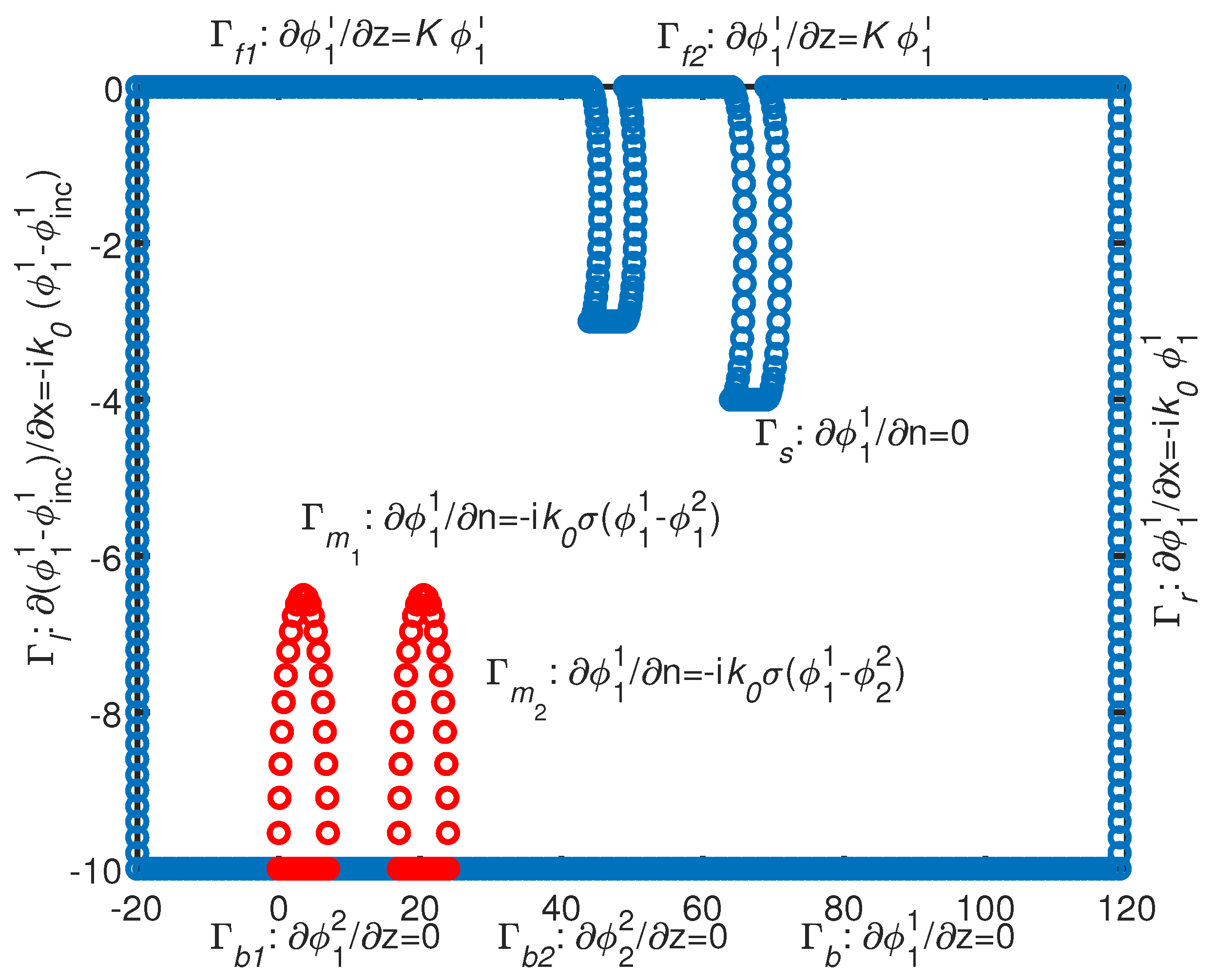
are termed the influence coefficients. To compute the influence coefficients as in Equation (10), the Gaussian integral formula is applied when the field point ( x , z ) and the source point ( x 0 , z 0 ) do not lie on the same boundary element. When the source point and the field point lie on the same boundary element, the influence coefficients, as in Equation (10), are computed analytically. Now, to generate the number of equations equal to the number of unknowns, the method of collocation is used, in which the source point runs over each boundary element (Figure 3).

2.2. Wave Scattering

In the case of wave scattering (see Figure 2a), the far-field radiation conditions given in Equation (6) are employed to solve the system of Equation (9) and determine the velocity potentials within the computational domain. Based on these potentials, the reflection and transmission coefficients, K r and K t , are evaluated using the expressions provided in Kar et al. [40]:
K r = | R 0 | = | ϕ 1 1 ( x , 0 ) e i k 0 x 1 | x =
and K t = | T 0 | = | ϕ 1 1 ( x , 0 ) | x = ,
where ϕ 1 1 ( , 0 ) , ϕ 1 1 ( , 0 ) are the potentials at the leftmost and rightmost panels of the free surface, respectively. The energy loss coefficient is
K D = 1 K r 2 K t 2 .

2.3. Wave Trapping

In the case of wave trapping by multiple semicircular porous structures in the presence of C -type floating breakwaters (as in Figure 2b), all boundary conditions are identical to those described earlier. However, instead of the lee-side far-field radiation condition in Equation (6), the following condition is imposed on the rigid shore-fixed wall to solve the system of Equation (9):
ϕ 1 1 n = 0 .
After obtaining the velocity potentials in the computational domain, the reflection coefficient K r is obtained from the formula
K r = | R 0 | = | ϕ 1 1 ( x , 0 ) e i k 0 x 1 | x = ,
where ϕ 1 1 ( , 0 ) is the potential at the leftmost panel of the free surface. The energy loss coefficient is
K D = 1 K r 2 .

2.4. Wave Forces

Horizontal force acting on the first perforated semicircle:
F x = i ρ ω Γ m [ ϕ 1 2 ϕ 1 1 ] . n x d Γ m .
Vertical force acting on the first perforated semicircle:
F z = i ρ ω Γ m [ ϕ 1 2 ϕ 1 1 ] . n z d Γ m .
The dimensionless form of the horizontal force and the vertical forces acting on the first perforated semicircle can be written (see Liu et al. [39]) as
C F x = | F x | 2 ρ g r ,
and C F z = | F z | 2 ρ g r ,
where r is the radius of the semicircle. In case of wave trapping, the dimensionless horizontal wave force acting on the shore-fixed vertical rigid wall (see Tsai et al. [41]) yields
K L h = ω g h 2 Γ L ϕ 1 1 n x d Γ L .

2.5. Free-Surface Elevation

The free-surface elevation is ξ ( x , t ) = ζ ( x ) e i ω t (see Figure 2), where ζ ( x ) can be expressed as (for details, see Kar et al. [40])
ζ ( x ) = i ω g ϕ 1 1 ( x ) .

3. Convergence of Numerical Solution and Validation

The convergence of the numerical solution is based on the size of the panel p s used to discretize the computational domain. The number of panels n p s are
n p s = Total boundary length of computational domain p s ,
where is the floor function.
To nullify the impact of evanescent wave mode disturbance, the far-field boundary conditions, as in Equation (6), are assumed at a distance of four times the water depth from the structure. Table 1 and Table 2 show that the values of the tabulated parameters converge to three decimal places for p s 0.05. Therefore, p s = 0.05 is taken in subsequent numerical computations.
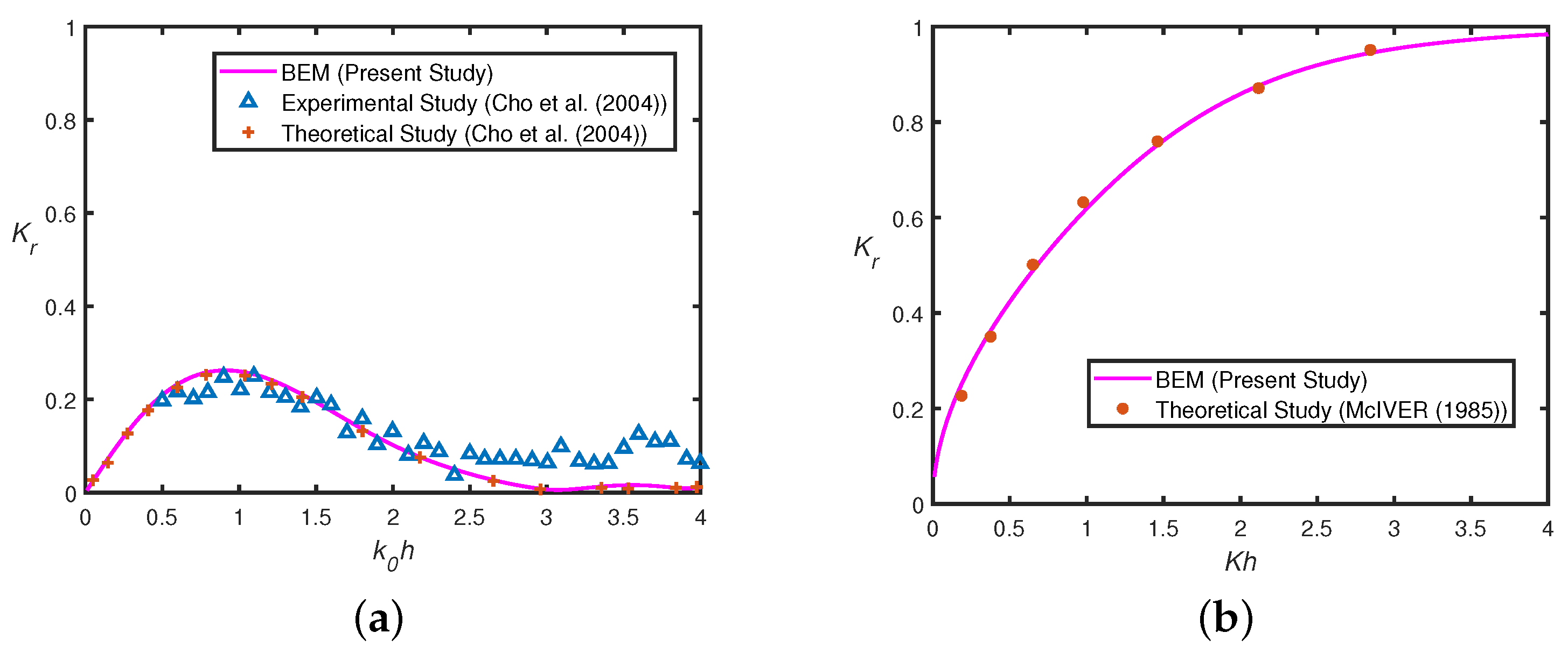
Figure 4a shows a comparison between the present numerical result with the experimental and the theoretical results of Cho et al. [42]. It is observed that the present BEM result agrees well with the analytical result of Cho et al. [42]. Moreover, the present BEM result follows a pattern similar to the experimental result of Cho et al. [42]. A deviation between experimental and present numerical results is due to the assumption that the fluid is inviscid in the present linearized model. Figure 4b shows a comparison of the result of the present study with that of McIVER [43] in the case of wave scattering by a floating rectangular-type breakwater, which is the limiting case of a C-type breakwater.
In Figure 5, the (a) reflection coefficient K r and (b) transmission coefficient K t are plotted as a function of the nondimensional wavenumber k 0 h for various values of the modified porous effect parameter G 0 for a semicircular hump placed on a rigid, impermeable flat bottom bed. Figure 5a reveals that the reflection coefficient decreases significantly when the value of the porosity parameter G 0 increases. This phenomenon is helpful to protect the seabed from scour and to ensure the safe navigation of vessels near the structure. It is noted that in Figure 5a,b, the lines represent the solution as obtained by using the present numerical method, and the symbols/markers are the results that are taken from Figs. 2 and 3 of Liu and Li [39]. Therefore, Figure 5 shows that the analytic results, K r and K t as in Liu and Li [39], agree well with the present numerical BEM results. Table 3 shows how the present numerical results compare with the existing analytical result of Liu and Li [39]. It is observed that the reflection and transmission coefficients, as computed numerically based on the BEM method, agree up to three decimal places with the analytical result of Liu and Li [39] in the case of wave scattering over a single perforated semicircular hump with radius r / h = 0.9 , and porosity G 0 = 0.5 .

4. Results and Discussion

To analyze the effects of different wave and structural parameters on wave scattering and wave trapping over porous semicircular humps placed near C-type breakwaters, code was developed using MATLAB software R2023A for the purpose of numerical computation. The physical parameters associated with the current study, such as water depth h = 10 (m), the modified porous effect parameter G 0 = 0.5 , and structural parameters such as the radius of the jth semicircular porous hump r j / h = 0.5 for j = 1 , 2 , 3 N , the gap between the jth and ( j + 1 ) th semicircular perforated humps d j / h ( = d / h ) = 1 for j = 1 , 2 , , N 1 , and the submerged depth of sea-side C -type breakwater D 1 / h = 0.24 , the submerged depth of lee-side C -type breakwater D 2 / h = 0.28 , the gap length between the C -type floating breakwaters D / h = 1 , the thickness of the C -type floating breakwater b 1 / h = b 2 / h ( = b / h ) = 0.2 , the gap between the C -type floating breakwater and the shore-fixed wall L / h = 2 , the gap between the bottom-standing semicircular hump and the C -type floating breakwater l / h = 1 were maintained constant unless stated otherwise. In Table 4, all the parametric values are summarized unless otherwise mentioned in the figure’s caption. In the subsequent study, it is assumed that all the semicircles have equal radii, i.e., r 1 / h = r 2 / h = r / h unless otherwise mentioned.

4.1. Wave Scattering

4.1.1. In the Absence of C -Type Breakwater

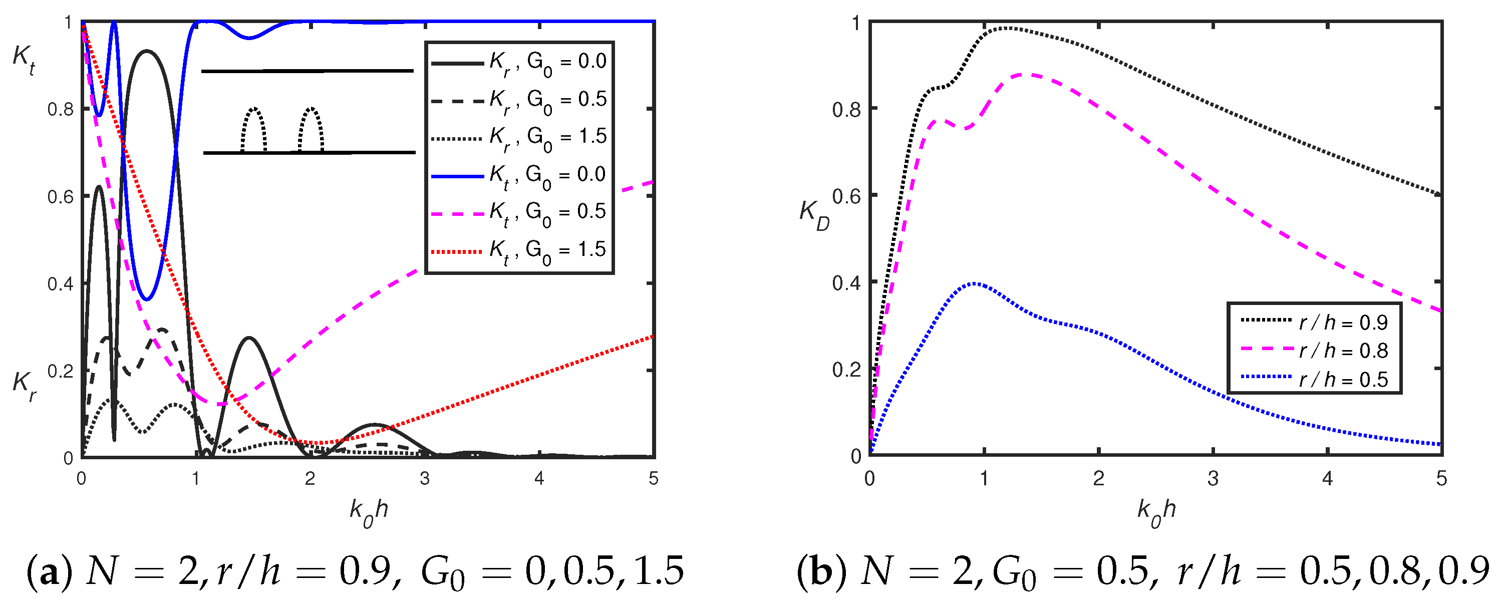
In Figure 6, the variation in (a) reflection and transmission coefficients K r and K t , and (b) dissipation coefficient K D , with G 0 = 0.5 , r / h = 0.9 , is plotted against dimensionless wavenumber k 0 h for double permeable semicircular humps in the absence of a vertical shore-fixed wall. In Figure 6a, the reflection coefficient K r follows an oscillatory decay pattern with increasing wavenumber k 0 h whilst sharp decay is observed for the transmission coefficient K t in the case of permeable double humps. In the case of impermeable semicircles, the subharmonic peak occurs between two harmonic peaks, which is similar to the authors’ earlier investigation, as in Kar et al. [40]. In addition, the number of zero-reflection points is greater in the case of impermeable humps as compared to permeable humps. Moreover, as the porosity G 0 increases, the peak amplitude in the reflection coefficient K r decreases. Furthermore, for larger k 0 h , the reflection coefficient K r diminishes irrespective of porosity G 0 . The reflection coefficient K r exhibits the decaying oscillatory pattern for smaller wavenumber, which is due to the occurrence of Bragg resonance. As the wavenumbers k 0 h increase, the contributions of both progressive and evanescent wave modes in the presence of semicircular humps diminish, which leads to a lowering of the Bragg resonance. Figure 6b reveals that the energy dissipation coefficient K D is higher for larger values of the semicircle radius r / h . It is observed that for a certain value of k 0 h , the energy loss is maximum. Figure 5a and Figure 6a reveal that the Bragg resonance is observed in the case of double perforated semicircular humps compared to that of a single semicircular hump. Figure 6b reveals that the energy dissipation coefficient K D reaches a maximum for a certain value of wavenumber k 0 h and then follows a decreasing pattern with an increasing wavenumber k 0 h . In addition, Figure 6b shows that the dissipation coefficient K D decreases with when the radius of perforated semicircular humps increase. As porosity G 0 increases, the semicircular humps dissipate a greater amount of incident wave energy. From Figure 6b, it can be concluded that nearly 90% of the wave energy can be dissipated in the double permeable semicircular hump with radius r / h = 0.9 and porosity G 0 = 0.5 .
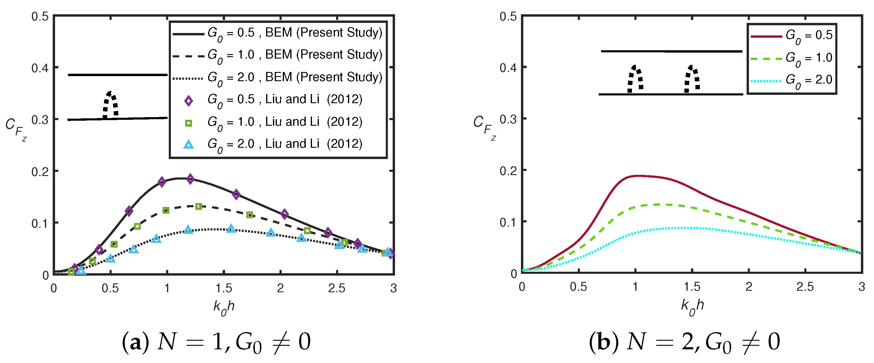
Figure 7 shows the variation in the vertical force C F z acting on the first semicircular hump in the case of (a) a single ( N = 1 ) and (b) double ( N = 2 ) humps with different values of porosity G 0 . Figure 7a demonstrates that the results from the current numerical method are in good agreement with the analytical solution reported by Liu and Li [39]. Figure 7a indicates that as the wavenumber k 0 h approaches zero, then C F z tends toward zero. Figure 7a shows that as the values of G 0 increase, the values of the vertical force C F z acting on the semicircular hump decrease. In Figure 7b, the vertical force C F z increases monotonically and then decreases with an increase in k 0 h . The maxima of the vertical force C F z are attained for a certain value of k 0 h , which is similar to that shown in Figure 7a. Figure 7b illustrates that the peak value of C F z decreases noticeably as the values of G 0 increase, which helps improve the stability of the hump against sliding.
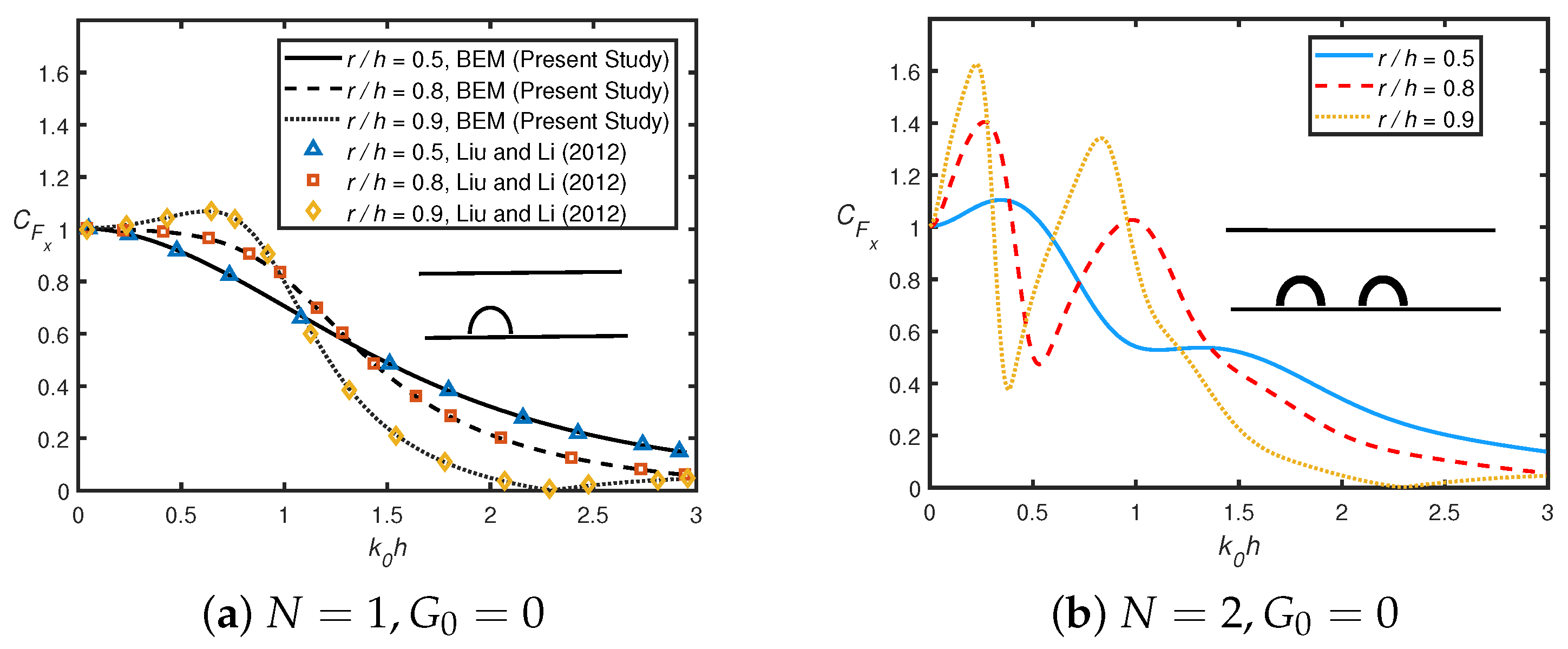
In Figure 8, the variation in dimensionless vertical force C F z on the first semicircle against wavenumber k 0 h is plotted in the case of (a) a single ( N = 1 ) and (b) double ( N = 2 ) humps for different values of the hump radius r / h with G 0 = 0 in the absence of a shore-fixed wall. In Figure 8a, the vertical force C F z agrees well with the analytical solution of Liu and Li [39]. In Figure 8b, when the semicircular hump is not perforated, the total vertical force decreases drastically for k 0 h > 1.5 . Moreover, the amplitude of the peaks in vertical force C F z follows a resonance pattern for smaller wavenumber k 0 h . In addition, the number of peaks is higher in the case of double humps as compared to a single hump. Both Figure 7 and Figure 8 reveal that for a smaller wavenumber, the peak amplitude in the vertical force C F z increases as the hump radius r / h increases. A comparison between Figure 7 and Figure 8 show that for k 0 h near zero, the vertical force converges to zero in the case of a permeable semicircle, while it converges to unity in the case of an impermeable semicircle.
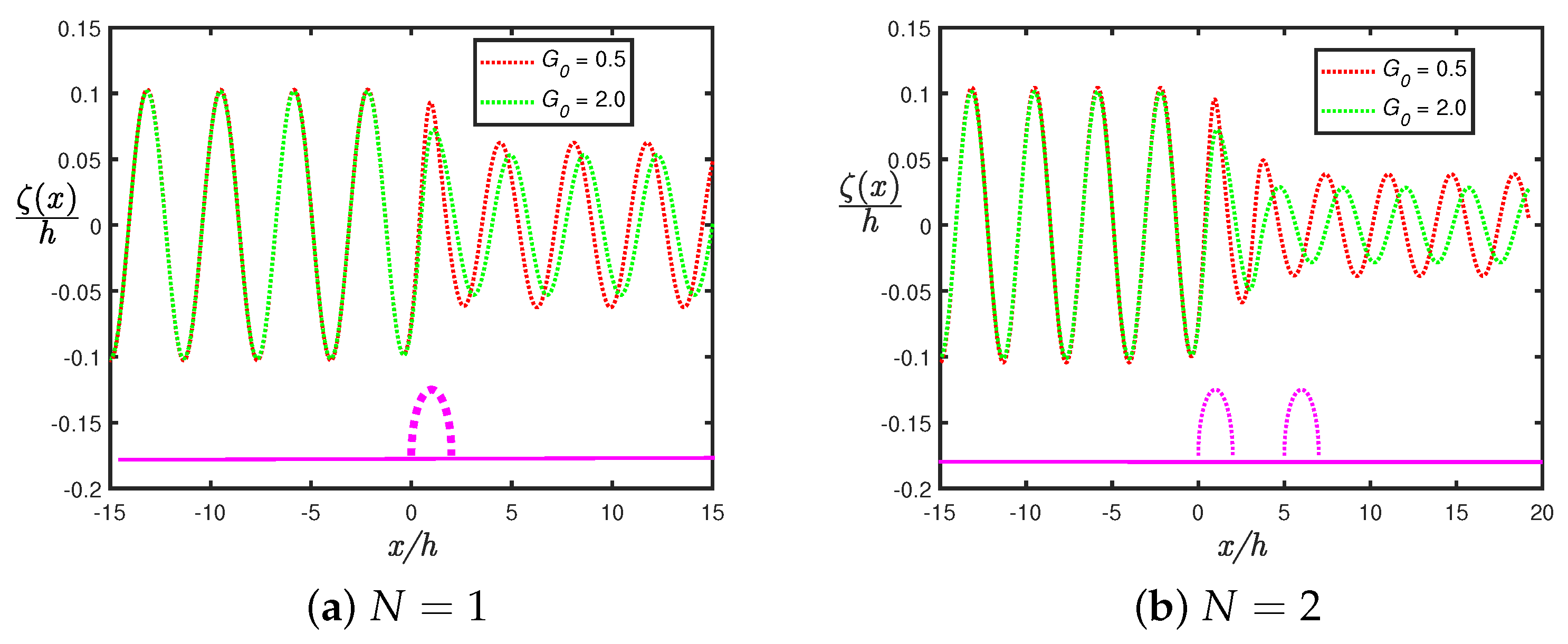
In Figure 9, the variation in the free-surface elevation ζ ( x ) / h against flume length x / h is plotted in the case of (a) a single ( N = 1 ) and (b) double ( N = 2 ) perforated semicircular humps for different values of porosity G 0 , with r / h = 0.9 , in the absence of a shore-fixed wall. In Figure 9a, the amplitude of free-surface elevation ζ ( x ) / h decreases as porosity G 0 increases in the case of a single perforated semicircle. There is a minor variation in the phase of the wave amplitude, which may be due to the absence of a gap length. Figure 9b reveals that the amplitude of free-surface elevation ζ ( x ) / h decreases drastically due to the presence of double perforated semicircular humps. Figure 9b shows that the variation in phase of the wave amplitude occurs with an increase in porosity G 0 , which is due to the gap length between the perforated semicircular humps. Moreover, the number of peaks in ζ ( x ) / h is greater in the case of two semicircular humps as compared to the single perforated hump. A comparison of Figure 9a with Figure 9b shows that as the number of perforated semicircles increases, the dissipation of waves increases. A similar phenomenon is seen in Figure 6.

4.1.2. In the Presence of C -Type Floating Breakwater

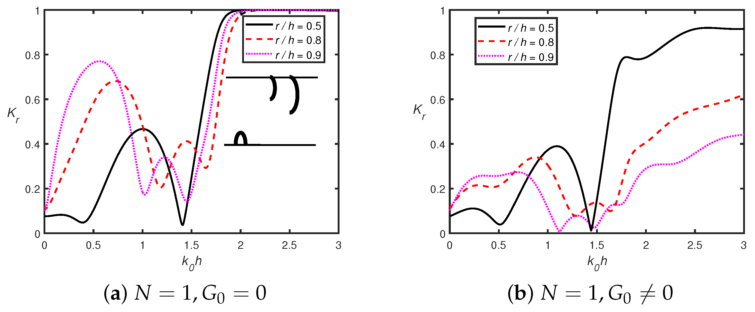
In Figure 10, the variation in the reflection coefficient K r against wavenumber k 0 h is plotted for different values of a single semicircular hump radius r / h when (a) G 0 = 0 and (b) G 0 = 0.5 with a gap distance between the semicircular hump and the leftmost breakwater of l / h = 2 . Figure 10a reveals that the reflection coefficient tends to unity for a larger wavenumber ( k 0 h > 2 ) . The observation is similar to that studied in the case of a floating dock placed near trenches/breakwater (as in Vijay et al. [17], McIVER [43]). Both plots in Figure 10a,b reveal that the overall wave reflection reduces in the presence of the hump’s porosity. Moreover, the peak amplitude in wave reflection decreases rapidly for a larger radius of the hump. The position of peaks and dips remains unchanged in the presence and absence of porosity. For a smaller wavenumber k 0 h < 1.8 , the wave reflection follows a resonating pattern, while it increases sharply for a higher wavenumber.
Figure 11 illustrates the variation in the reflection coefficient K r against wavenumber k 0 h for different values of hump porosity G 0 in the case of (a) a single ( N = 1 ) and (b) double ( N = 2 ) semicircular humps with radius r / h = 0.9 and gap distance between rightmost hump and leftmost floating breakwater l / h = 2 . In Figure 11a, the peak amplitude in the reflection coefficient K r decreases for k 0 h > 2.5 with an increase in porosity G 0 . Moreover, the area under the wave reflection curve reduces as the porosity increases. For smaller wavenumber k 0 h < 1.8 , the wave reflection follows the resonating pattern irrespective of hump porosity G 0 . Figure 11b reveals that the reflection coefficient K r decreases as porosity G 0 increases. A comparison of Figure 11a with Figure 11b shows that when the number of perforated semicircular humps increases, the area under the wave reflection curve decreases rapidly. The phenomenon is due to the dissipation of the incident wave energy by the porous semicircular hump.

4.2. Wave Trapping

4.2.1. In the Absence of C -Type Floating Breakwater

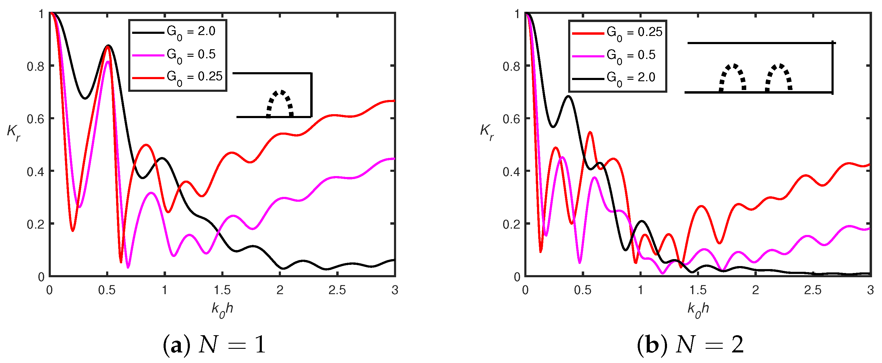
Figure 12 reveals that in the presence of a shore-fixed wall, the reflection coefficient K r follows an oscillatory decay pattern for G 0 = 2 and tends to zero as wavenumber k 0 h increases. Moreover, for smaller values of porosity G 0 and when k 0 h > 1.5 , the oscillatory pattern in the reflection coefficient K r increases with an increase in the wavenumber k 0 h . In addition, the span width of the oscillations in wave reflection coefficient K r becomes narrower with an increase in wavenumber k 0 h . Both plots in Figure 12a,b show that when wavenumber k 0 h becomes larger, the reflection coefficient K r increases as the values of porosity G 0 decrease. This scenario occurs due to the constructive interference of progressive waves between the semicircular hump and the shore-fixed wall. A comparison of Figure 12a with Figure 12b shows that when the number of semicircles increases, the corresponding peak amplitude in the reflection coefficient K r decreases. The reduction in peak amplitude in wave reflection K r occurs because the perforated semicircular hump allows a portion of the incoming wave to pass through.
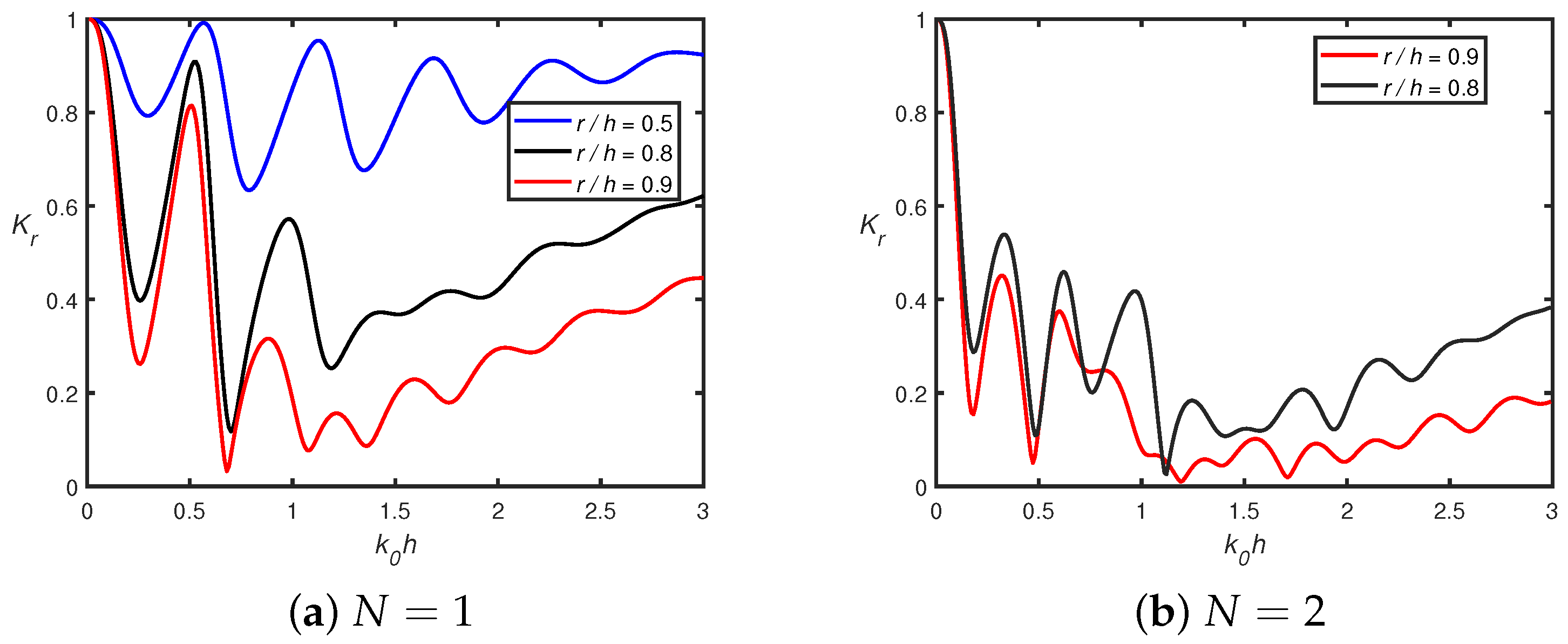
Figure 13 illustrates the change in the reflection coefficient K r versus nondimensional wavenumber k 0 h in the case of (a) a single ( N = 1 ) and (b) double ( N = 2 ) semicircular humps with porosity G 0 = 0.5 for different values of hump radius r / h in the presence of a shore-fixed vertical wall. Figure 13 shows that the reflection coefficient K r exhibits a resonance pattern when wavenumber k 0 h increases which is a similar observation as in Figure 12. It can be seen from Figure 13a,b that the peak amplitude in the reflection coefficient K r is smaller for a configuration with double humps ( N = 2 ) compared to a single hump ( N = 1 ) . Moreover, as the radius of the hump increases, the span width of the reflected wave amplitude reduces significantly. In both plots in Figure 13a,b, the reduction in wave reflection is due to the dissipation of wave energy by the permeability of the semicircular hump. Furthermore, the shift in the maxima and minima in the wave reflection coefficient K r is due to the interplay of constructive and destructive interference between the incoming and reflected waves. When the number of humps increases, then the peak amplitude in wave reflection decreases which is similar with the findings of Tsai et al. [41].
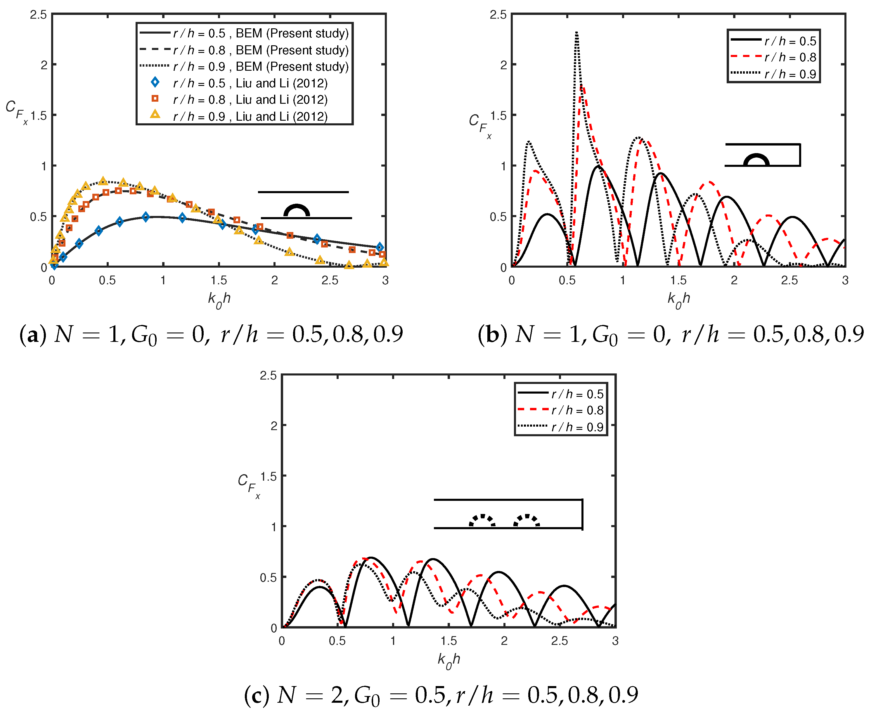
In Figure 14, the variation in the dimensionless horizontal force C F x against the nondimensional wavenumber k 0 h is plotted in the absence (Figure 14a) and presence (Figure 14b,c) of a shore-fixed vertical wall. In Figure 14a, it is observed that the solutions obtained by the present numerical method agree well with the analytical solution of Liu and Li [39]. Figure 14a reveals that C F z is monotonic with increases in k 0 h for r / h = 0.5 , 0.8 , reaches a maximum for smaller k 0 h , and is zero when k 0 h = 2.3 . Moreover, the peak amplitude in the horizontal force C F x increases with an increase in the radius of the semicircle r / h . Figure 14b reveals that in the presence of a shore-fixed wall, the C F x follows an oscillatory pattern with an increase in wavenumber k 0 h . For a larger wavenumber, the peak amplitude in C F x decreases with an increase in wavenumber k 0 h . Moreover, the zero horizontal force points increase with an increase in the semicircle radius value r / h . In addition, a larger number of peaks is observed for a greater value of semicircle radius r / h . A comparison of Figure 14a with Figure 14b shows that C F x reaches a maximum at a certain value of wavenumber k 0 h . In addition, the oscillatory peaks in C F x are higher in the presence of a shore-fixed wall compared to the absence of a shore-fixed wall, which is due to the occurrence of trapped wave energy. Moreover, Figure 14c shows that the horizontal force acting on the first semicircular hump C F x attains a maximum for a certain value of wavenumber k 0 h and follows an oscillating pattern with an increase in wavenumber k 0 h . The number of zero horizontal force points occurs with an increase in wavenumber k 0 h . It is observed that the number of zero horizontal force points is greater when r / h = 0.5 compared to the radius taken as r / h = 0.8 , 0.9 . Furthermore, the peak amplitude in C F x decreases with an increase in hump radius r / h . This scenario is expected as more waves are dissipated when the radius of the semicircular hump increases.
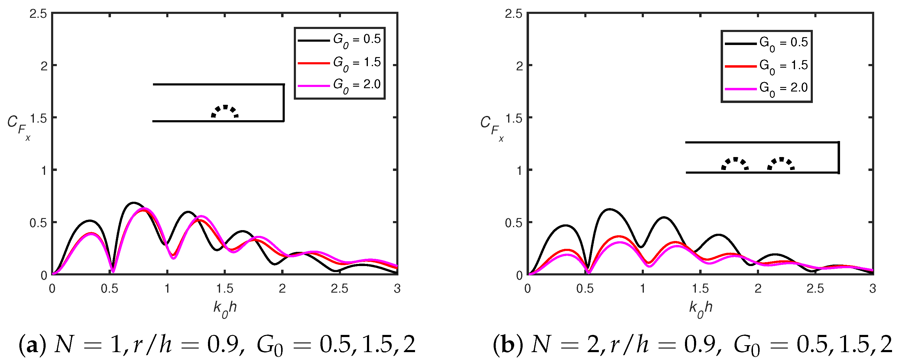
Figure 15 illustrates the variation in dimensionless horizontal force C F x against nondimensional wavenumber k 0 h for different values of (a) porosity G 0 , with r / h = 0.9 , and (b) semicircle radius r / h with G 0 = 0.5 in the presence of a shore-fixed vertical wall. Figure 15 shows that the horizontal force C F x follows an oscillating pattern as the wavenumber k 0 h increases. This scenario does not occur in the case of a single perforated semicircular hump in the absence of a shore-fixed vertical wall, as shown in Figure 14a. In Figure 15b, it is observed that as the value of G 0 increases, the value of horizontal force C F x decreases. The number of peaks in the horizontal force C F x remains unchanged for wavenumber k 0 h < 1.5 when porosity G 0 increases. Figure 15b reveals that for a larger wavenumber k 0 h , with an increase in radius of a semicircular hump r / h , the amplitude of the peak in horizontal force C F x decreases. This phenomenon occurs because wave dissipation is greater for a larger radius of the semicircular hump. The bandwidth in the horizontal force C F x decreases with an increase in the porosity of the semicircle. Moreover, the number of peaks in the horizontal force does not change with an increase in the porosity of the semicircle G 0 . This phenomenon occurs because of the occurrence of a standing wave between the wall and the semicircular hump.

4.2.2. In the Presence of C -Type Floating Breakwater

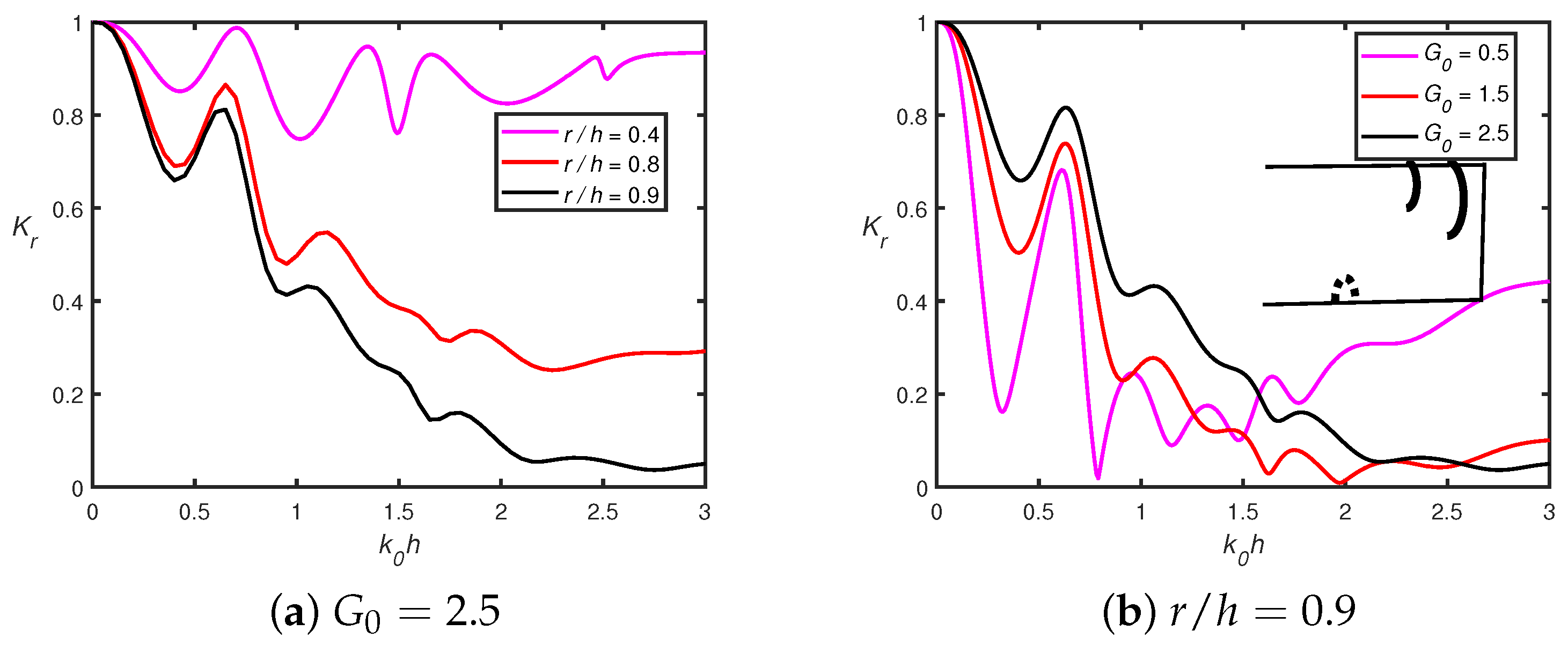
Figure 16 reveals the variation in the reflection coefficient K r versus wavenumber k 0 h for different values of (a) the radius of the semicircular hump r / h with G 0 = 2.5 and (b) porosity of the semicircular hump G 0 with radius r / h = 0.9 . In Figure 16a, the wave reflection coefficient K r decreases with an increase in the wavenumber k 0 h . When the radius increases, the wave reflection decreases rapidly. It is observed that for a larger radius r / h , the dissipation of wave energy is greater. Figure 16b shows that the reflection coefficient K r follows an oscillatory pattern with a change in porosity G 0 . It is observed that wave reflection is greater when G 0 = 2.5 compared to G 0 = 1.5 , which is due to the occurrence of Bragg resonance.
In Figure 17, the change in reflection coefficient K r against wavenumber k 0 h is plotted for different values of (a) porosity parameter G 0 , with r / h = 0.9 and (b) radius of semicircular hump r / h with G 0 = 0 in the case of double semicircular humps N = 2 with gap distance l / h = 2 , L / h = 1 , gap between the breakwaters D / h = 0.5 , breakwater width b / h = 0.1 , submerged depth of first breakwater D 1 / h = 0.24 , and submerged depth of second breakwater D 2 / h = 0.28 . Figure 17 shows that wave reflection follows the oscillatory decaying pattern with increasing wavenumber k 0 h . Moreover, it is observed that the variation in K r occurs due to a change in the gap distance between the breakwaters D / h for a smaller wavenumber, while no change in wave reflection coefficient K r is observed for a higher wavenumber.
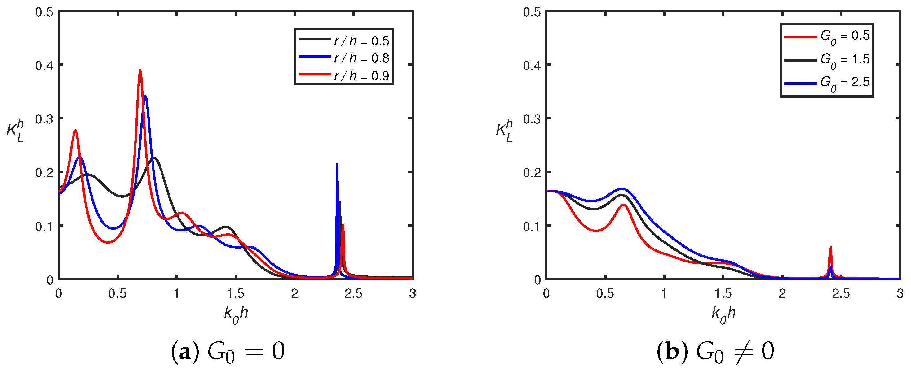
Figure 18 reveals the variation in horizontal force K L h acting on the shore-fixed rigid wall in the presence of a single semicircular hump and double C-type breakwaters for different values of (a) radius r / h with G 0 = 0 and (b) porosity G 0 with r / h = 0.9 with gap distance l / h = 2 , L / h = 1 , gap between the breakwaters D / h = 0.5 , breakwater width b / h = 0.1 , submerged depth of first breakwater D 1 / h = 0.24 , and submerged depth of second breakwater D 2 / h = 0.28 . Figure 18 shows that K L h exhibits an oscillating decay pattern as wavenumber k 0 h increases. In Figure 18a, peak amplitude in K L h increases when the radius of the impermeable semicircular hump increases for a lower wavenumber. In addition, as radius r / h increases, peaks in K L h shift towards the lower wavenumber k 0 h . Figure 18b illustrates that the variation in K L h occurs for a smaller wavenumber, while horizontal force K L h tends to zero for a larger wavenumber. Moreover, peak amplitude in K L h increases as porosity increases, which is due to the occurrence of Bragg resonance. A comparison of Figure 18a with Figure 18b shows that in the presence of porosity G 0 , peak amplitude in K L h reduces drastically. The phenomenon happens due to the loss of energy by the porous semicircular hump.

5. Conclusions

In the present study, a numerical investigation was carried out using the multi-domain BEM within the framework of small-amplitude water wave theory. The scattering coefficients, such as reflection, transmission coefficient, dissipation coefficient, vertical/horizontal wave forces acting on the first perforated semicircle, and horizontal wave forces acting on the shore-fixed vertical wall, were examined in the absence/presence of double floating breakwaters. The roles of various physical parameters, such as hump radius, porosity, and the gap between the adjacent sides of the humps, along with the gap between the two C -type floating breakwaters, were studied. The reflection, transmission coefficients, and free-surface elevation were plotted to understand the effective role of the porous hump in Bragg scattering. The following conclusions can be made:
  • In the presence of a shore-fixed wall, the higher Bragg reflection occurs for smaller wavenumbers, which is due to constructive interference between the semicircles and the rigid wall. The peak amplitude in the reflection coefficient decreases as the number of semicircles increases.
  • The wave reflection decreases as the radius of the perforated semicircle becomes larger. Therefore, the radius of the perforated semicircle is crucial in diminishing the energy of the incoming waves.
  • Horizontal force acting on the first semicircular hump follows the Bragg resonance pattern in the presence of a shore-fixed wall, whilst it is not observed in the absence of a shore-fixed wall.
  • Moreover, the horizontal force acting on the shore-fixed wall drastically decreases in the presence of porosity as compared to its absence.
  • In addition, when wavenumbers shift to zero, the vertical force converges to zero for multiple permeable semicircular humps, whilst it converges to unity in the case of multiple impermeable semicircular humps.
  • The amplitude of wave attenuation decreases when the number of perforated bottom-standing semicircular humps increases.
The construction of a fixed-detached breakwater near a rigid vertical wall may constitute an alternative for reducing the wave load on seawalls by absorbing the incident wave energy. The present study was based on linearized potential flow theory. Consequently, the nonlinear wave effects were not studied. The hydrodynamic results under linear water wave theory may differ from the results under real ocean conditions involving high waves. The incorporation of nonlinear wave theory will be considered in future work. Furthermore, the current analysis was carried out in a two-dimensional framework. Although coastal structures are three-dimensional in nature, the results of 2-D structures can still be useful for analyzing 3-D structures. The extension of the present study in a three-dimensional framework will be considered in future research work.

Author Contributions

Validation, P.K.; Software, P.K.; Methodology, H.B. and P.K.; Writing—Original Draft Preparation, P.K. and H.B.; Writing—Review and Editing, P.K. and H.B.; Investigation, P.K., H.B., and D.N.; Formal Analysis, P.K. and H.B.; Funding Acquisition, H.B. and D.N. All authors have read and agreed to the published version of the manuscript.

Funding

H.B. acknowledges the financial support from the National Science and Technology Council of Taiwan (Grant No. NSTC 113-2222-E-019-003).

Data Availability Statement

The original contributions presented in this study are included in the article. Further inquiries can be directed to the corresponding author.

Conflicts of Interest

The authors declare no conflicts of interest.

References

  1. Mei, C.C.; Black, J.L. Scattering of surface waves by rectangular obstacles in waters of finite depth. J. Fluid Mech. 1969, 38, 499–511. [Google Scholar] [CrossRef]
  2. Porter, R.; Porter, D. Interaction of water waves with three-dimensional periodic topography. J. Fluid Mech. 2001, 434, 301–335. [Google Scholar] [CrossRef]
  3. Xie, J.J.; Liu, H.W. Analytical study of Bragg resonances by a finite periodic array of congruent trapezoidal bars or trenches on a sloping seabed. Appl. Math. Model. 2023, 119, 717–735. [Google Scholar] [CrossRef]
  4. Liu, Y.; Li, H.J.; Zhu, L. Bragg reflection of water waves by multiple submerged semi-circular breakwaters. Appl. Ocean Res. 2016, 56, 67–78. [Google Scholar] [CrossRef]
  5. Ding, Y.; Liu, H.W.; Lin, P. Quantitative Expression of the Modified Bragg’s Law for Bragg resonances of water waves excited by five types of artificial bars. Phys. Fluids 2024, 36, 047130. [Google Scholar] [CrossRef]
  6. Akarni, H.; Mabchour, H.; Aarabi, L.; Mordane, S. Wave reflection by rectangular breakwaters for coastal protection. Fluid Dyn. Mater. Process. 2024, 20, 579. [Google Scholar] [CrossRef]
  7. Goyal, D.; Martha, S. Optimal allocation of multiple rigid bars with unequal draft to enhance Bragg reflection of surface gravity waves. Ships Offshore Struct. 2025, 1–10. [Google Scholar] [CrossRef]
  8. Anilkumar, S.; Panduranga, K. Analysis of Bragg reflection phenomenon induced by an array of submerged twin-wing breakwaters. Phys. Fluids 2025, 37, 077184. [Google Scholar] [CrossRef]
  9. Teng, B.; Zhang, X.; Ning, D. Interaction of oblique waves with infinite number of perforated caissons. Ocean Eng. 2004, 31, 615–632. [Google Scholar] [CrossRef]
  10. Dhinakaran, G.; Sundar, V.; Sundaravadivelu, R. Review of the research on emerged and submerged semicircular breakwaters. Proc. Inst. Mech. Eng. M J. Eng. Marit. Environ. 2012, 226, 397–409. [Google Scholar] [CrossRef]
  11. Liu, Y.; Li, Y.C.; Teng, B. Interaction between oblique waves and perforated caisson breakwaters with perforated partition walls. Eur. J. Mech. B Fluids 2016, 56, 143–155. [Google Scholar] [CrossRef]
  12. Koley, S.; Sahoo, T. Wave interaction with a submerged semicircular porous breakwater placed on a porous seabed. Eng. Anal. Bound. Elem. 2017, 80, 18–37. [Google Scholar] [CrossRef]
  13. Li, A.j.; Liu, Y.; Liu, X.; Zhao, Y. Analytical and experimental studies on Bragg scattering of water waves by multiple submerged perforated semi-circular breakwaters. Ocean Eng. 2020, 209, 107419. [Google Scholar] [CrossRef]
  14. Sharma, M.; Kaligatla, R.; Sahoo, T. Wave interaction with a submerged floating tunnel in the presence of a bottom mounted submerged porous breakwater. Appl. Ocean Res. 2020, 96, 102069. [Google Scholar] [CrossRef]
  15. Khan, M.B.; Behera, H. Analysis of wave action through multiple submerged porous structures. J. Offshore Mech. Arct. Eng. 2020, 142, 011101. [Google Scholar] [CrossRef]
  16. Li, A.j.; Sun, X.l.; Liu, Y.; Li, H.j. Analysis of water wave interaction with multiple submerged porous reef balls. J. Eng. Math. 2021, 127, 26. [Google Scholar] [CrossRef]
  17. Vijay, K.; Venkateswarlu, V.; Sahoo, T. Bragg scattering of surface gravity waves by an array of submerged breakwaters and a floating dock. Wave Motion 2021, 106, 102807. [Google Scholar] [CrossRef]
  18. Ni, Y.l.; Teng, B. Bragg resonant reflection of water waves by a Bragg breakwater with porous trapezoidal bars on a sloping permeable seabed. Appl. Ocean Res. 2021, 114, 102770. [Google Scholar] [CrossRef]
  19. Han, M.; Wang, C. Potential flow theory-based analytical and numerical modelling of porous and perforated breakwaters: A review. Ocean Eng. 2022, 249, 110897. [Google Scholar] [CrossRef]
  20. Pan, D.; Xu, L.; Chen, H. Experimental study on seabed-fixed cylinders with truncated porous shells. Ocean Eng. 2025, 311, 117902. [Google Scholar]
  21. Venkateswarlu, V.; Vijay, K.; Sannasiraj, S.A. Enhancement in Hydrodynamic Performance of a Quarter-Circular Breakwater Using a Porous Shield. J. Offshore Mech. Arct. Eng. 2025, 147, 051204. [Google Scholar] [CrossRef]
  22. Sahoo, G.; Venkateswarlu, V.; Martha, S. Mitigation of structural response on a floating elastic plate in the presence of multiple porous structures. Appl. Ocean Res. 2025, 154, 104412. [Google Scholar] [CrossRef]
  23. Penney, W.G.; Price, A.T.; Martin, J.; Moyce, W.; Penney, W.G.; Price, A.; Thornhill, C. Part I. The diffraction theory of sea waves and the shelter afforded by breakwaters. Philos. Trans. R. Soc. A Math. Phy. Sci. 1952, 244, 236–253. [Google Scholar]
  24. Chang, J.Y.; Tsai, C.C. Wave forces on a partially reflecting wall by oblique Bragg scattering with porous breakwaters over uneven bottoms. J. Mar. Sci. Eng. 2022, 10, 409. [Google Scholar] [CrossRef]
  25. Halvorson, B.; Huang, Z. Study of effects of perforation layouts on wave energy dissipation caused by a submerged perforated breakwater in front of a vertical seawall. Ocean Eng. 2024, 311, 119025. [Google Scholar] [CrossRef]
  26. Swami, K.C.; Koley, S. Wave trapping by porous breakwater near a rigid wall under the influence of ocean current. Sci. Rep. 2024, 14, 17325. [Google Scholar] [CrossRef]
  27. Dora, R.R.; Mondal, R.; Mohanty, S.K. Wave trapping by porous breakwater near a wall under the influence of ocean current. Ocean Eng. 2024, 303, 117820. [Google Scholar] [CrossRef]
  28. Matsui, T.; Kato, K.; Shirai, T. A hybrid integral equation method for diffraction and radiation of water waves by three-dimensional bodies. Comput. Mech. 1987, 2, 119–135. [Google Scholar] [CrossRef]
  29. Hess, J.; Smith, A. Calculation of nonlifting potential flow about arbitrary three-dimensional bodies. J. Ship Res. 1964, 8, 22–44. [Google Scholar] [CrossRef]
  30. Magkouris, A.; Bonovas, M.; Gerostathis, T.; Belibassakis, K. A 3D BEM Model for the Hydrodynamic Analysis and Design of Heaving WEC Arrays Attached to a Breakwater. Sustainability 2023, 15, 12777. [Google Scholar] [CrossRef]
  31. Brebbia, C.A.; Dominguez, J.; Tassoulas, J.L. Boundary Elements: An Introductory Course. J. Appl. Mech. 1991, 3, 860. [Google Scholar] [CrossRef]
  32. Sauter, S.; Schwab, C. Boundary Element Methods; Springer: Berlin/Heidelberg, Germany, 2011. [Google Scholar]
  33. Mei, C. The Applied Dynamics of Ocean Surface Waves; World Scientific: Singapore, 1989. [Google Scholar]
  34. Show, T.K.; Hirdaris, S.; Datta, R. A Fully Coupled Time-Domain BEM-FEM Method for the Prediction of Symmetric Hydroelastic Responses of Ships with Forward Speed. Shock Vib. 2022, 2022, 4564769. [Google Scholar] [CrossRef]
  35. Evans, D.; Linton, C. Trapped modes in open channels. J. Fluid Mech. 1991, 225, 153–175. [Google Scholar] [CrossRef]
  36. Linton, C.; McIver, P. Embedded trapped modes in water waves and acoustics. Wave Motion 2007, 45, 16–29. [Google Scholar] [CrossRef]
  37. Barman, S.; Das, S.; Sahoo, T.; Meylan, M. Scattering of flexural-gravity waves by a crack in a floating ice sheet due to mode conversion during blocking. J. Fluid Mech. 2021, 916, A11. [Google Scholar] [CrossRef]
  38. Yu, X.; Chwang, A. Wave-induced oscillation in harbor with porous breakwaters. J. Waterw. Port Coast 1994, 120, 125–144. [Google Scholar] [CrossRef]
  39. Liu, Y.; Li, H.J. Analysis of wave interaction with submerged perforated semi-circular breakwaters through multipole method. Appl. Ocean Res. 2012, 34, 164–172. [Google Scholar] [CrossRef]
  40. Kar, P.; Koley, S.; Sahoo, T. Scattering of surface gravity waves over a pair of trenches. Appl. Math. Model. 2018, 62, 303–320. [Google Scholar] [CrossRef]
  41. Tsai, C.C.; Behera, H.; Hsu, T.W. Analysis of water wave interaction with multiple submerged semi-circular porous structures. Arch. Appl. Mech. 2023, 93, 2693–2709. [Google Scholar] [CrossRef]
  42. Cho, Y.S.; Lee, J.I.; Kim, Y.T. Experimental study of strong reflection of regular water waves over submerged breakwaters in tandem. Ocean Eng. 2004, 31, 1325–1335. [Google Scholar] [CrossRef]
  43. McIVER, M. Diffraction of water waves by a moored, horizontal, flat plate. J. Eng. Math. 1985, 19, 297–319. [Google Scholar] [CrossRef]
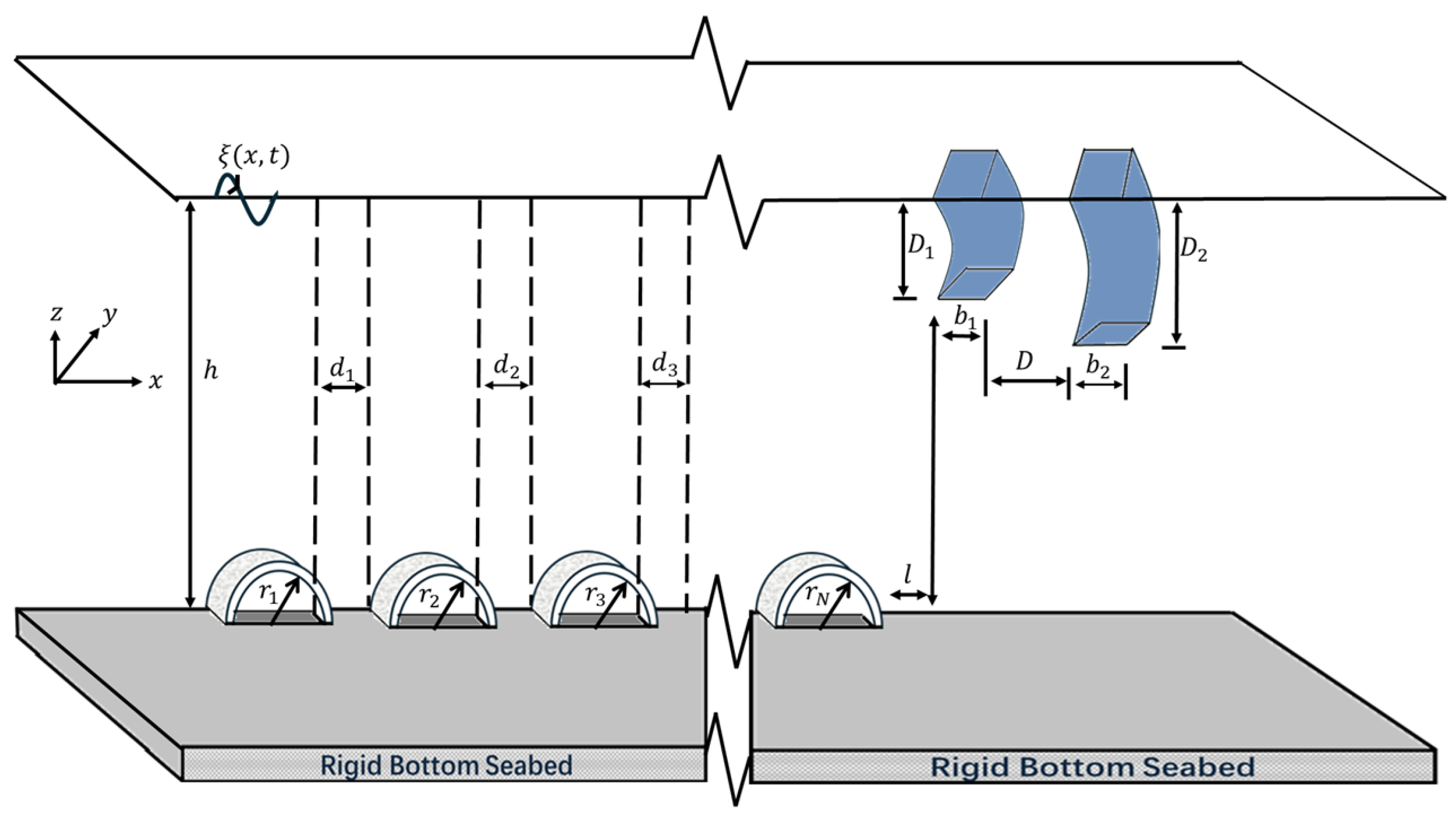
Figure 1. A 3-D sketch of permeable semicircular humps for wave scattering in the presence of C -type double rigid breakwaters.
Mathematics 13 03372 g001
Figure 2. A 2-D sketch of permeable semicircular humps for (a) wave scattering and (b) wave trapping in the presence of C -type double breakwaters.
Mathematics 13 03372 g002
Figure 3. Computational domain of the BEM in the case of double bottom-standing porous semicircular humps and C-type double rigid breakwaters. Γ f 1 and Γ f 2 indicate the outer and inner free-surface boundaries of double breakwaters. Γ b represents the inner and outer bottom boundaries of the semicircular humps. Γ m 1 , Γ b 1 , and Γ m 2 , Γ b 2 show the interface and bottom boundaries of the first and second humps, respectively. Γ s represents the boundaries of rigid breakwaters. Γ l and Γ r indicate the left and right far-field boundaries.
Mathematics 13 03372 g003
Figure 4. Distribution of the reflection coefficient K r in the case of an impermeable (a) submerged bottom-standing rectangular bar with length 0.5 h and width 0.5 h , respectively, and (b) floating rectangular breakwater with submerged depth D / h = 0.1 , and width b 1 / h = 1 [42,43].
Mathematics 13 03372 g004
Figure 5. Changes in (a) the reflection coefficient K r and (b) the transmission coefficient K t for different values of porosity G 0 with r / h = 0.9 , h = 10 (m) in the absence of a shore-fixed vertical wall (Liu and Li [39]).
Mathematics 13 03372 g005
Figure 6. Variation in (a) reflection and transmission coefficients K r and K t for different G 0 ’s with r / h = 0.9 , and (b) dissipation coefficient K D with G 0 = 0.5 for different values of radius r / h in the case of double humps and in the absence of a shore-fixed wall.
Mathematics 13 03372 g006
Figure 7. Variation in the vertical force C F z in the case of (a) a single ( N = 1 ) and (b) double ( N = 2 ) perforated semicircular humps with r / h = 0.9 at different values of porosity G 0 (Liu and Li [39]).
Mathematics 13 03372 g007
Figure 8. Variation in the vertical force C F z in the case of (a) a single ( N = 1 ) and (b) double ( N = 2 ) imperforate semicircular humps ( G 0 = 0 ) and for different radii r / h in the absence of a shore-fixed wall (Liu and Li [39]).
Mathematics 13 03372 g008
Figure 9. The free-surface elevation ζ ( x ) / h versus flume length x / h in the case of (a) a single ( N = 1 ) and (b) double ( N = 2 ) perforated semicircular humps at different values of porosity G 0 , with r / h = 0.9 , in the absence of shore-fixed vertical wall.
Mathematics 13 03372 g009
Figure 10. Variation of the reflection coefficient K r versus nondimensional wavenumber k 0 h for different values of radius r / h in the case of an (a) impermeable ( G 0 = 0 ) and (b) permeable G 0 = 0.5 single semicircular hump with gap distance l / h = 2 , submerged depth of first breakwater D 1 / h = 0.24 , submerged depth of second breakwater D 2 / h = 0.28 , width of breakwaters b / h = 0.1 , and gap between breakwaters D / h = 0.5 .
Mathematics 13 03372 g010
Figure 11. Variation in the reflection coefficient K r versus nondimensional wavenumber k 0 h for different values of hump porosity G 0 in the case of (a) a single ( N = 1 ) and (b) double ( N = 2 ) semicircular humps with gap distance l / h = 2 , submerged depth of first breakwater D 1 / h = 0.24 , submerged depth of second breakwater D 2 / h = 0.28 , width of breakwaters b / h = 0.1 , and gap between breakwaters D / h = 0.5 .
Mathematics 13 03372 g011
Figure 12. Changes in the reflection coefficient K r with varying porosity G 0 in the case of (a) a single ( N = 1 ) and (b) double ( N = 2 ) semicircular humps with radius r / h = 0.9 , gap distance between vertical shore-fixed wall and rightmost semicircular hump L / h = 1 in the absence of floating breakwaters.
Mathematics 13 03372 g012
Figure 13. Variation in the reflection coefficient K r for different radii r / h in the case of (a) single ( N = 1 ) and (b) double perforated semicircular humps ( N = 2 ) with porosity G 0 = 0.5 in the presence of a shore-fixed vertical wall with a gap distance between vertical wall and rightmost semicircular hump L / h = 1 .
Mathematics 13 03372 g013
Figure 14. Variation in the dimensionless horizontal force C F x on the impermeable semicircular hump in the (a) absence and (b,c) presence of a shore-fixed vertical wall with gap distance from wall to rightmost semicircular hump L / h = 1 (Liu and Li [39]).
Mathematics 13 03372 g014
Figure 15. Variation in the dimensionless horizontal force C F x acting on the first semicircular hump in the case of (a) a single ( N = 1 ) and (b) double ( N = 2 ) humps for different values of porosity G 0 , with r / h = 0.9 , in the presence of a shore-fixed vertical wall with gap distance between wall and rightmost semicircular hump L / h = 1 .
Mathematics 13 03372 g015
Figure 16. K r against k 0 h for different values of (a) semicircle radius r / h with G 0 = 2.5 , and (b) porosity G 0 with r / h = 0.9 in the case of a single perforated semicircle with double floating breakwaters in the presence of shore-fixed wall with gap distance l / h = 2 , L / h = 1 , gap between the breakwaters D / h = 0.5 , breakwater width b / h = 0.1 , submerged depth of first breakwater D 1 / h = 0.24 , and submerged depth of second breakwater D 2 / h = 0.28 .
Mathematics 13 03372 g016
Figure 17. K r against k 0 h for different values of (a) gap length between breakwaters D / h and (b) gap between rightmost breakwater and vertical wall L / h with a semicircular hump radius r / h = 0.9 and porosity G 0 = 2.5 .
Mathematics 13 03372 g017
Figure 18. The horizontal force acting on the shore-fixed wall K L h against wavenumber k 0 h for different values of (a) the radius of a single semicircular hump r / h with G 0 = 0 and (b) porosity G 0 with a semicircular hump radius r / h = 0.9 .
Mathematics 13 03372 g018
Table 1. Values of K r , K t , and K D in the case of a single perforated semicircle for different values of p s with r / h = 0.9 and G 0 = 2 .
k 0 h = 0.5 k 0 h = 1.5 k 0 h = 2.5
p s K r K t K D K r K t K D K r K t K D
0.1 0.11040.83260.29450.02140.39220.84560.01000.19170.9631
0.05 0.11040.83260.29450.02130.39220.84560.01020.19170.9631
0.01 0.11040.83260.29450.02130.39220.84560.01020.19160.9631
Table 2. Values of forces acting on the single semicircle C F x , C F z for different values of p s with r / h = 0.9 and G 0 = 2 .
k 0 h = 0.5 k 0 h = 1.5 k 0 h = 2.5
p s C F x C F z C F x C F z C F x C F z
0.1 0.30310.03150.34340.08660.14990.0568
0.05 0.30350.03070.34340.08670.14980.0569
0.01 0.30340.03060.34340.08660.14980.0568
Table 3. The values of K r and K t in the case of a single perforated semicircle with radius r / h = 0.9 and porosity G 0 = 0.5 .
k 0 h = 0.5 k 0 h = 1.5 k 0 h = 2.5
K r K t K r K t K r K t
Liu and Li [39]0.31620.61030.06310.39750.01850.6041
BEM (present study)0.31610.61060.06330.39750.01850.6043
Table 4. The values of structural and wave parameters used in the numerical computation.
ParametersValuesParametersValues
Sea-side breakwater depth D 1 / h 0.24Porosity G 0 0.5
Lee-side breakwater depth D 2 / h 0.28Water depth h10 (m)
Gap between breakwaters D / h 1Radius of semicircle r / h 0.5
Breakwaters thickness b / h 0.1Gap from breakwater to semicircle l / h 1
Gap between the semicircles d / h 1Gap from vertical wall to breakwater L / h 2
Disclaimer/Publisher’s Note: The statements, opinions and data contained in all publications are solely those of the individual author(s) and contributor(s) and not of MDPI and/or the editor(s). MDPI and/or the editor(s) disclaim responsibility for any injury to people or property resulting from any ideas, methods, instructions or products referred to in the content.