Article

Nonlinear Shear Waves in Compressible Media: Occurrence of Strong Shocks

by
Vladimir Bratov
1,* and
Sergey V. Kuznetsov
2
1
School of Computing, Engineering & The Built Environment, Edinburgh Napier University, Edinburgh EH10 5DT, UK
2
School of Structural Mechanics, Moscow State University of Civil Engineering, 129337 Moscow, Russia
*
Author to whom correspondence should be addressed.
Mathematics 2025, 13(12), 1991; https://doi.org/10.3390/math13121991
Submission received: 4 April 2025 / Revised: 5 May 2025 / Accepted: 12 June 2025 / Published: 17 June 2025
(This article belongs to the Special Issue Computational Mathematics: Advanced Methods and Applications)

Abstract

Apparently for the first time, shear shock wave fronts (shear shocks) are observed in a hyperfoam at the propagation of shear waves. The hyperfoam is modelled by the Ogden compressible hyperelastic potential. A possible appearance of the shear shocks may explain the kinetic and strain energy attenuation along with heat release at the propagation of shear waves in hyperfoams. The analysis is based on the Cauchy formalism for equations of motion, equations of energy balance, and FE analysis for solutions of the constructed nonlinear hyperbolic equation.

1. Introduction

1.1. An Overview

It has long been known that discontinuities in strain, stress and phase velocity, known as strong shock wave fronts, propagating faster than the ambient speed of sound, can arise in liquids and gases [1,2,3,4,5,6,7,8,9,10,11,12,13,14]. A similar situation occurs with strong shock wave fronts in nonlinear solids, where the discontinuities in the same field variables may arise when faster parts of a wave start to overtake slower ones [15,16,17,18,19]. It should also be noted that there are very few experimental studies on the formation and propagation of strong shocks in hyperelastic solids, highlighting the urgent need for further investigation.
It is known that in the case of strong shock wave fronts in solids, the shock wave velocity V for an elastic acoustic wave takes an intermediate value between phase velocities on either sides of the surface of discontinuity [20,21,22]:
V c ; c + ,
where
c = lim x x 0 0 n 0 c ( x ) ;                               c + = lim x x 0 + 0 n 0 c ( x ) .
Herein, x 0 belongs to the shock wave front; c is the phase velocity; n 0 is the unit normal to the shock wave front at x 0 ; and limits in Equation (2) are taken along non-tangential directions to the shock wave front. Applying Hadamard’s compatibility condition [23], the propagation velocity V of the shock wave can be found by the following equation:
V = c F n n ,
where F is the deformation gradient; the square brackets denote a jump in the non-tangential limits for the corresponding field variables approaching a point on the shock wave front, e.g.,
[ c ] = c + c .
Thus, if c = c + and, hence, c = 0 , then V = 0 . Most of the work on shock waves in solids relates to nonlinear P-waves in isotropic hyperelastic solids [24,25,26,27,28,29,30,31,32] or elastic–plastic P-waves [33,34,35,36,37].
In a number of works the shock wave fronts formed by the propagation of nonlinear shear waves polarised orthogonally to the direction of propagation are concerned [38,39,40,41]. Shear shocks can be generated by even weak shear waves due to relatively small shear moduli and significantly large nonlinearity at shear deformation [42]. Most of the works on nonlinear shear waves and shear shocks relate to incompressible solids. The assumption of incompressibility corresponds to the known experimental facts on various artificial and natural organic materials [43,44] and simplifies the governing equations [45,46].
Meanwhile, quite a large number of soft polymer foams, including aerogels, exhibit high compressibility [47,48,49]. Moreover, some aerogels may have auxetic properties associated with negative Poisson’s ratio [50] and can demonstrate negative compressibility [51,52,53,54,55]. To account high compressibility of foam materials a special class of hyperelastic potentials, known as hyperfoams, was developed [56,57,58,59,60,61]. As was mentioned by [59], these potentials ascend to a less common hyperelastic potential introduced in [62] and a family of Hill’s potentials [63,64].
Another remark concerns the principal difference between shear shock waves and vortex sheets in solids [23]. The propagation velocity of a shear wave is discontinuous at the shear shock wave front according to Equations (1)–(4) and for a shear shock wave front.
c c n n = 0 ,
where n is the unit normal to the shock wave front, the propagation velocity of the vortex sheet is necessarily orthogonal to the vortex sheet.
c n = 0 .
Moreover, the propagation velocity is necessary continuously [23,65,66].

1.2. Current Research

The current research is aimed at analysing the formation and propagation of shock waves generated by excitation of a shear wave in a hyperelastic medium satisfying one of Hill’s hyperelastic potentials (hyperfoams), which is suited for modelling highly compressible foams. It will be shown below that the occurrence of shear shock waves accompanying the propagation of a wave with a smooth wave front leads to (i) the appearance of discontinuities in strain, stress, and propagation velocity; (ii) a gradual decrease in both displacement and strain magnitudes with distance from the excitation plane; (iii) a gradual decrease in both strain-specific energy and kinetic-specific energy with distance; and (iv) the release of heat caused by the corresponding decrease in mechanical energy. Thus, due to these observations, compressible foams modelled by the Hill hyperelastic potential can be used as shear wave absorbers, working without viscous or dry friction dampers.
The analysis is based on constructing the nonlinear equation of motion for a (pure) shear wave, applying the equation of energy balance at the shock wave front, and performing computations by the finite element (FE) method for spatial discretisation coupled with the explicit energy preserving predictor–corrector finite difference (FD) Lax–Wendroff method [67,68].

2. Principal Equations

2.1. Pure Shear

2.1.1. Displacement Field

The displacement field corresponding to a plane shear wave can be represented in the following form [69,70]:
u ( x , t ) = m f x , t ) ,
where u is the displacement field; x = x n is the scalar variable varying along wave vector; t is the time; m is a vector defining the polarisation of the wave; it is assumed that m n = 0 ; c is the propagation velocity; and f is a scalar-valued wave function. In the following analysis, f is assumed continuously differentiable in x and t variables. The quantity
γ = 2 1 x f
is known as the amount of (pure) shear or nominal shear [66].

2.1.2. Deformation Gradient

Consider the deformation gradient F related to pure shear [23,66]:
F = I + γ m n + n m ,
where I is the unit tensor. It is assumed that γ < 1 , which ensures the non-degeneracy of tensor F . Applying the Jordan normal form decomposition to the deformation gradient (9) yields
F = Q F D F Q F t ,
where the superscript denotes the transposition; Q F is orthogonal, and D F is diagonal:
Q F = 1 2 1 2 0 1 2 1 2 0 0 1 ;                                                 D F = k = 1 3 λ k e k e k .
Herein, e k are the mutually orthogonal vectors, associated with vectors m and n through the following relations:
e 1 = m + n 2 ;                                 e 2 = m n 2 ;                                   e 3 = m × n .
Eigenvalues λ k in Equation (11) are known as the principal stretches, and they are connected to the nominal shear by the following relations:
λ 1 = 1 + γ ;                             λ 2 = 1 γ ;                             λ 3 = 1 .
In view of Equation (9), the principal invariants of tensor F become
I 1 F I F = 3 ;                       I 2 F 1 2 I F 2 I F F = 3 γ 2 ;                     J det F = 1 γ 2 .
The change in volume J under pure shear is known as the Kelvin effect [66]. Another important remark concerns the compressibility condition stemming from Equations (9) and (13); the account of compressibility is essential for modelling hyperfoams that exhibit extremely high compressibility across the entire range of admissible stretches.

2.1.3. Left Cauchy–Green Deformation Tensor

For the following analysis introduce the left Cauchy–Green deformation tensor [66].
B F F t = I + γ 2 m m + n n + 2 γ m n + n m = 1 + γ 2 2 γ 0 2 γ 1 + γ 2 0 0 0 1 ,
which similarly to Equation (10) can be decomposed into Jordan normal form
B = Q B D B Q B t ,
where
Q B = Q F ;                                                 D B = k = 1 3 λ k 2 e k e k .
In view of Equations (13) and (17), the corresponding invariants of tensor B become
I 1 B = 2 γ 2 + 3 ;                       I 2 B = 3 + γ 4 ;                       I 3 B = ( 1 γ 2 ) 2 .

2.2. Ogden–Hill Compressible Hyperelastic Potential

Consider the Ogden–Hill compressible potential, one of the most general forms of which is as follows [64]:
W ( λ 1 , λ 2 , λ 3 ) = m = 1 M C m α m k = 1 3 λ k α m 3 + 1 β J α m β 1 ,
where M is the positive integer; C m are dimensional coefficients, associated with elastic moduli; and α m ,   β are some real numbers. Following [59], consider a specific form of potential (19), with M = 1 ,     α 1 = 2 ,     β = 1 2 , which is well suited for modelling compressible foams [25,71].
W ( λ 1 , λ 2 , λ 3 ) = μ 0 4 k = 1 3 λ k 2 + 2 J 5 ,
where μ 0 > 0 has the meaning of the (initial) shear modulus at small γ 0 . In [59,62,64], the parameter β is suggested to be taken as
β = ν 1 2 ν ,
where ν is the Poisson’s ratio, assumed to be independent of stretches λ k . However, in [56,57], no restrictions were imposed.

2.3. Principal Stresses

The Cauchy stress tensor can be defined by the following equation [66]:
σ ( λ ) = 2 J 1 W B B .
Tensor σ can be written in terms of its principal stresses ([70], Equation 4.3.44):
σ ( λ ) = m = 1 3 σ m ( λ ) e m e m = J 1 m = 1 3 λ m W λ m e m e m ,
In view of Equation (20), the principal stresses become
σ 1 ( γ ) = μ 0 γ 2 2 γ 2 γ 3 2 1 + γ 3 1 γ ;                       σ 2 ( γ ) = μ 0 γ 2 2 γ 2 + γ 3 2 1 γ 3 1 + γ ;                         σ 3 ( γ ) = μ 0 γ 2 2 1 γ 2 .
Introducing Cauchy shear stress ( τ ) [66] acting on planes with unit normal m and n , we arrive at
τ = 2 1 μ 0 γ 1 γ 2 3 m n + n m .
For infinitesimal shear strain, Equation (24) gives the following expressions for the principal components, written up to o ( γ ) :
σ 1 ( γ ) = μ 0 γ ;               σ 2 ( γ ) = μ 0 γ ;               σ 3 ( γ ) = 0 ;               τ ( γ ) = μ 0 γ .

2.4. Tangent Modulus and Shear Wave Velocity

Differentiating Equation (25) with respect to γ yields the tangent shear modulus:
μ ( γ ) = μ 0 1 + 5 γ 2 ( 1 + γ ) 4 ( 1 γ ) 4 .
Now, taking into account Equation (14) and the relation for the material density [70]:
ρ ( γ ) ρ 0 J = ρ 0 1 γ 2 ,
the propagation velocity for the considered nonlinear shear wave becomes
c S ( γ ) μ ( γ ) ρ ( γ ) = c S 0 1 + 5 γ 2 1 γ 2 ( 1 γ 2 ) 2 ,
where c S 0 is the initial shear wave velocity at γ 0 :
c S 0 = μ 0 ρ 0 .

2.5. Equation of Motion

The nonlinear hyperbolic equation of motion for the considered plane wave (7) can be written in the following form [66]:
x τ γ n = ρ γ m t t 2 f ( x , t ) ) .
In view of Equations (8) and (25), the equation becomes
μ 0 ( 1 + 5 γ 2 ) 2 1 γ 2 4 x x 2 f ( x , t ) = ρ ( γ ) t t 2 f ( x , t ) ,
from where noting expressions (28) and (29), we arrive at
c S 0 2 2 + 5 x f ( x , t ) 2 2 x f ( x , t ) 2 3 x x 2 f ( x , t ) = t t 2 f ( x , t ) .
Equation (33) is the desired nonlinear hyperbolic secular equation.

2.6. Initial and Boundary Conditions

Consider a plane wave generated by a triangle-type excitation at x = 0
f ( x , t ) x = 0 = f 0 × 0 ,                                     t 0 t ,                                     0 < t T / 2 T t ,                   T / 2 < t T 0 ,                                   t > T ,
where f 0 is the complex magnitude; T is the triangle base; thus
supp f ( x , t ) x = 0 = 0 ;     T .
The Sommerfeld attenuation condition is imposed at x [72]:
t :             lim x f ( x , t ) = 0 ;             lim x x f ( x , t ) = 0 .
Equation (36) ensures the absence of non-decaying solutions at infinity. Conditions (34) and (36) should be supplemented by the initial conditions:
x :           f ( x , t ) t = 0 = 0 ;               t f ( x , t ) t = 0 = 0 .

2.7. Equations of Energy Balance

Following [20,73], the equation of energy balance can be written in the following form:
0 t F ( τ ) d τ = E k + E s + Q ,
where F is the energy flux caused by the applied excitation at x = 0 ; Q is the heat release:
  Q 0 t 0 q ( x , τ ) d x d τ ,
q is the specific heat; E k and E s are kinetic and strain energy, respectively,
E k = 1 2 0 t 0 ρ ( λ ( x , τ ) ) τ u ( x , τ ) 2 d x d τ ;             E s = 0 t 0 W λ ( x , τ ) d x d τ .
Following [20,65,66], Equations (38) and (39) for heat release should be accomplished by the equation of entropy production:
T d S d Q ,
where T is the temperature, and S is the entropy. This inequality is essential for capturing the dependence of physical properties on temperature. However, in the present analysis, it is assumed that the considered shock waves are isentropic everywhere except at the wave front; see [20,65] for the conditions governing isentropic shock waves.
When a shock wave appears, Equation (38) requires an additional equation stating the energy balance at the discontinuity [23,65]:
ρ 0 V W + 1 2 ρ 0 V c S 2 = τ c S + Q ,
where the square brackets denote the jump at the discontinuity; and V is the velocity of the moving shock wave.

2.8. Numerical Modelling

To numerically solve the nonlinear hyperbolic Equation (33) with boundary and initial conditions (34)–(37), and with an account of equations for the energy balance (38), (41), the FE method for spatial discretisation is used combined with the finite difference (FD) approach for integration in the time domain. The explicit Lax–Wendroff energy preserving predictor–corrector numerical scheme is used in the time domain [67] with the Courant–Friedrichs–Lewi (CFL) condition imposed on the time increment.
Δ t < Δ t C F L min Δ x max γ c S ( γ ) ,
where Δ t is the time increment; Δ t C F L is the upper bound for the known for the stable time increment, known as the CFL increment; and Δ x is the diameter of spatial mesh element. Condition (42) ensures the achievement of numerically stable solutions [74].
The applied Lax–Wendroff two step predictor–corrector FD scheme can be written as [67,68]
f x j + 1 ; t n + 1 / 2 = 1 2 f x j + 1 ; t n + f x j ; t n                                                                         Δ t 2 Δ x H f x j + 1 ; t n H f x j ; t n ,
where x j is the spatial node; t n is the node in the time domain; and H is the nonlinear function associated with the left-hand side of Equation (33):
H f ( x , t ) = c S 0 2 2 + 5 x f ( x , t ) 2 2 x f ( x , t ) 2 3 .
To reduce non-physical oscillations, the median filter was applied to the obtained strain and stress fields:
g * ( t i ) = 1 2 m + 1 k = 0 m g ( t i ± k ) ,
where 2 m + 1 is the filter order, and the asterisk denotes the filtered function. According to empirical estimates median filters of orders 7 ÷ 15 provide reasonable smoothness while preserving shock-related discontinuities.

3. Numerical Analysis

3.1. The Model

Consider a plane strain model with a shear displacement field (34) acting at the bottom of the model with vertical non-reflecting PML boundaries [75,76]; see Figure 1.
The number of plane quadrilateral elements with reduced integration varied in the range N [ ~ 10 K ; 1200 K ] . The mesh convergence test revealed that at N 800 K , the results were visually almost indistinguishable; thus, N 800 K was taken for further analysis, yielding Δ t C F L 5 × 10 3   s . The initial pulse duration in Equation (34) was taken to satisfy the empirical estimate, ensuring small non-physical oscillations at the back wave fronts [77].
T > 25 × Δ t
where Δ t is the time increment from the CFL condition (42). In view of condition (46) and the obtained estimate for Δ t C F L , the upper bound becomes T > 0.125   s . Instead of imposing the Sommerfeld attenuation condition (36) at x , the points of observation were chosen in such a way as to ensure the absence of reflected waves from the right end of the rod.

3.2. Shear Waves and Shear Shocks

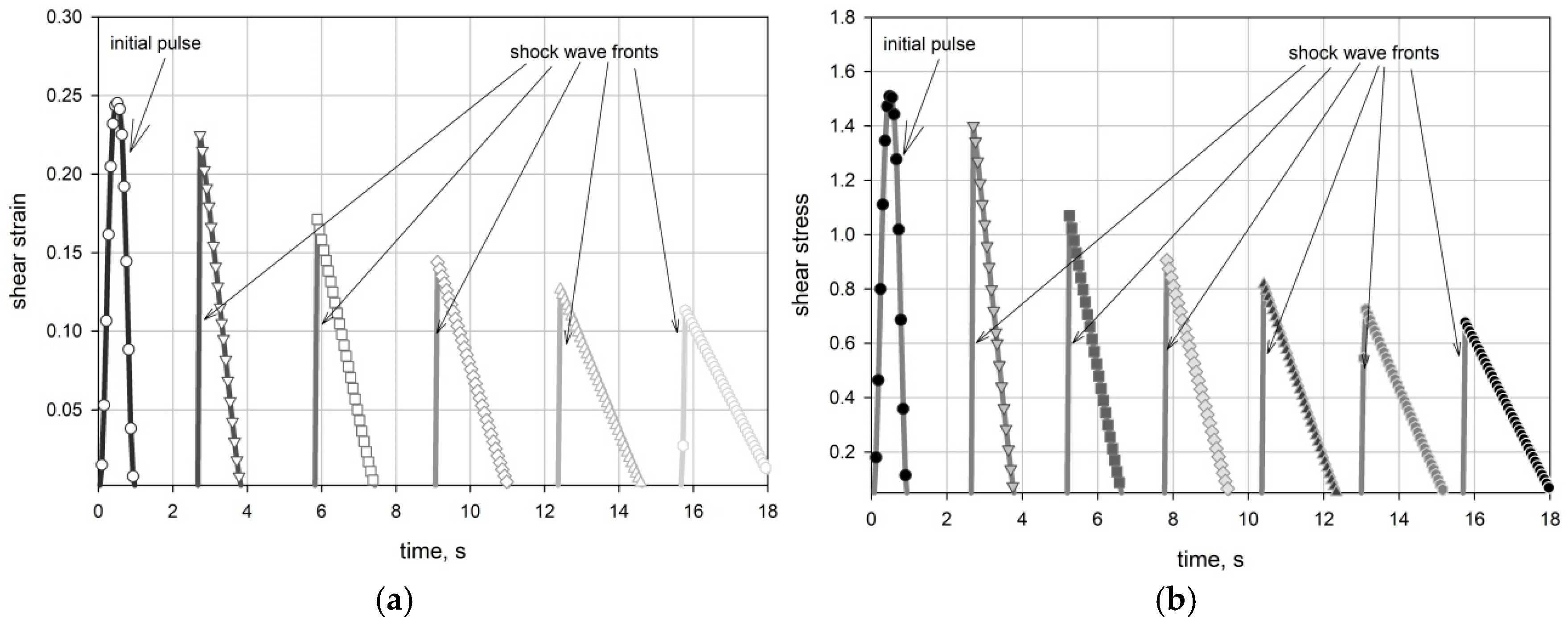
The plots for shear strain and the corresponding shear vs. time at different points of observation are shown in Figure 2.
The plots in Figure 2 reveal (i) the decay of the amplitudes of both the Cauchy shear stress and the nominal shear strain with distance from the applied source; (ii) the appearance of discontinuities (shock wave fronts) in both strain and stress; and (iii) the decrease in the propagation velocity behind the shock wave front resulting in pulse spreading.
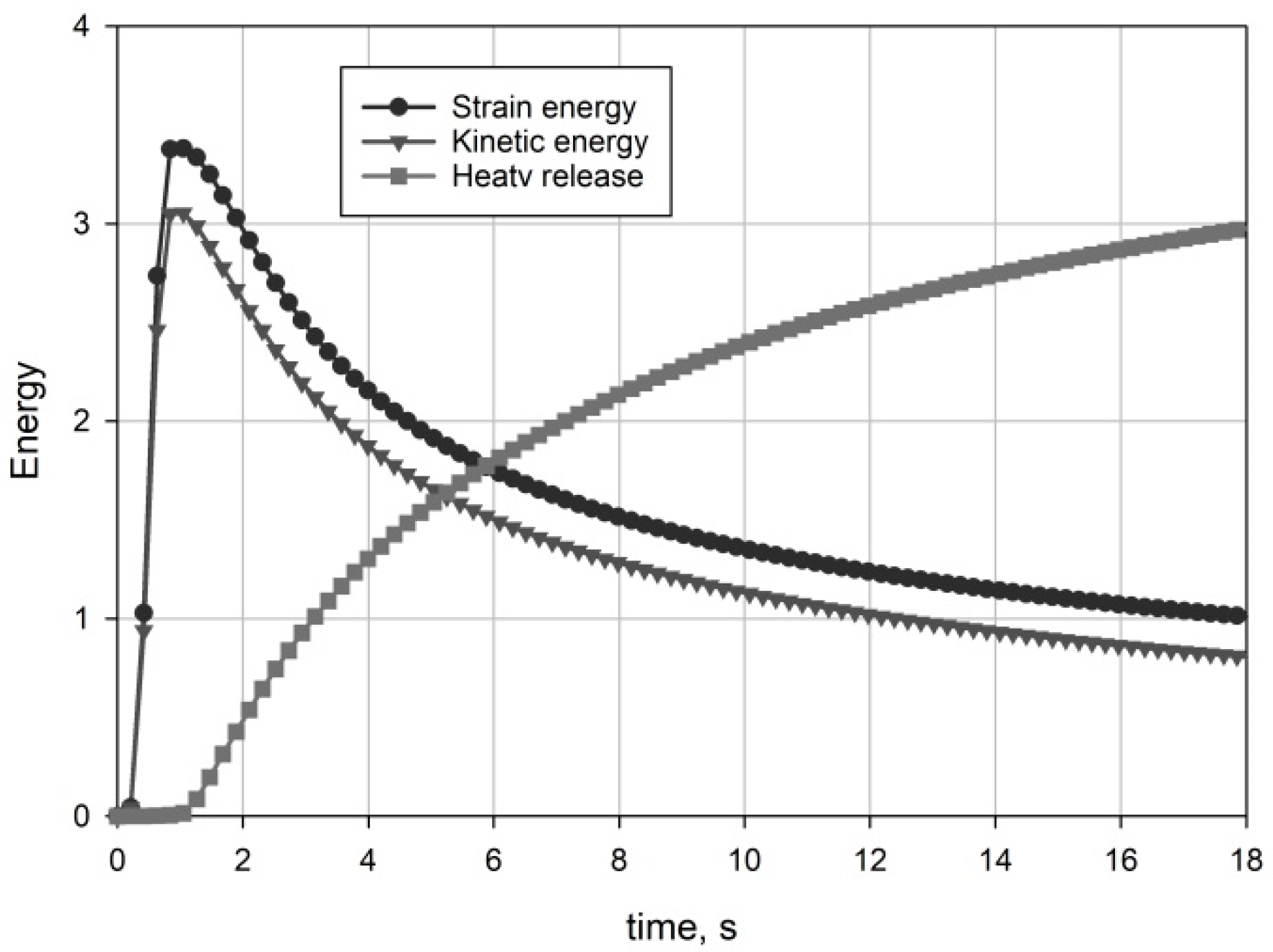
The strain and kinetic energy variation with time for the whole model, along with the heat release, is plotted in Figure 3, revealing (i) both strain and kinetic energy decay with time while the shear pulse propagates, which is caused by the decreased strain and stress magnitudes with distance from the source; (ii) at the same time, heat is released to compensate for the decrease in mechanical energy; and (iii) a discrepancy between strain and kinetic energy can be observed, indicating the nonlinear nature of the travelling wave [65].
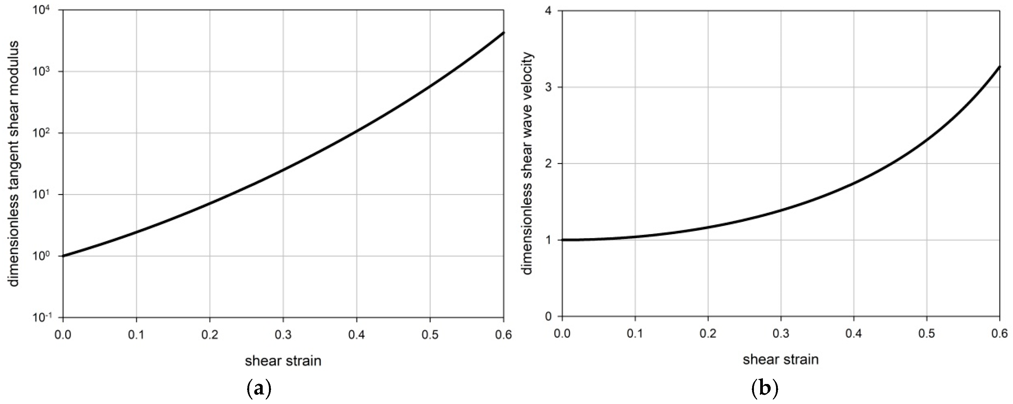
And, finally, the variations in the tangent shear modulus (27) and shear wave velocity (29) with shear strain are plotted in Figure 4.
The plots in Figure 4 are plotted in terms of the corresponding dimensionless quantities marked with an asterisk.
μ * = μ μ 0 ;                                 c S * = c S c S 0 .
Both tangent modulus and shear wave velocity vary exponentially vs. shear strain. The plots for shear wave velocity in Figure 4b and for strain variation with time in Figure 2a imply the appearance of discontinuity [ c ] in shear wave velocity.

4. Concluding Remarks

The performed analysis applied to the propagation of a triangle pulse in a compressible foam, modelled by the Ogden–Hill potential (20), reveals the following:
(i)
The appearance of discontinuities (shocks) in both strain and stress (Figure 2); the observed shocks are caused by the overtaking of slower moving parts of the delta-like pulse by faster ones.
(ii)
The decrease in strain and stress magnitudes of the propagating pulse with distance from the excitation source (Figure 2).
(iii)
Spreading out the pulse over distance caused by spatial dispersion (Figure 2).
(iv)
The decrease in both kinetic and strain energy with a simultaneous increase in thermal energy (Figure 3), which is caused by the formation and propagation of shocks [20,66]
(v)
The appearance of a discrepancy between strain and kinetic energy (Figure 4), which is caused by the physical nonlinearity of the considered medium [65,73].
These observed phenomena can have a wide range of possible applications: from the creation of microvibration isolators in microelectromechanical systems (MEMS) [78] to more substantial vibration isolators in the automotive and aerospace industries [79]; in all these cases, the vibration isolators do not contain viscous or dry friction dampers, due to the dissipation of mechanical energy in a hyperelastic material, modelled by the considered Ogden–Hill potential. It is also worth noting that shock waves, which are, in fact, propagating discontinuities in solid media, differ significantly from elastic waves. While elastic waves propagating in a lossless elastic or hyperelastic medium do not cause attenuation of mechanical energy, shock waves necessarily lead to energy attenuation accompanied by corresponding heat release [65,66].
A final remark concerns the triangle pulses considered in (34), which generated strong shocks when a slower-moving positive pulse was overtaken by a faster negative pulse. It can be shown that the specific shape of the pulses is not critical for shock formation; sinusoidal pulses, for example, could also be used instead of triangular ones. Thus, it can be anticipated that the pulse shape has little influence on the occurrence of shock formation. In this context, see [18,28], where sinusoidal pulses were shown to generate shocks in bi-modular media.

Author Contributions

Conceptualization, S.V.K.; Writing—original draft, S.V.K.; Writing—review & editing, V.B. All authors have read and agreed to the published version of the manuscript.

Funding

The work of S.V.K. was funded by the Ministry of Science and Higher Education of RF, grant FSWG-2023-0004.

Data Availability Statement

The original contributions presented in this study are included in the article. Further inquiries can be directed to the corresponding author.

Conflicts of Interest

The authors declare no conflict of interest.

References

  1. Cui, X. Shock waves: From gas dynamics to granular flows. Int. J. Aeronaut. Aerosp. Eng. 2019, 1, 7–9. [Google Scholar] [CrossRef]
  2. Gray, J.M.N.T.; Cui, X. Weak, strong and detached oblique shocks in gravity driven granular free-surface flows. J. Fluid Mech. 2007, 579, 113–136. [Google Scholar] [CrossRef]
  3. Graziani, F.; Moldabekov, Z.; Olson, B.; Bonitz, M. Shock physics in warm dense matter: A quantum hydrodynamics perspective. Contrib. Plasma Phys. 2021, 62, 202100170. [Google Scholar] [CrossRef]
  4. Menounou, P.; Blackstock, D.T. A new method to predict the evolution of the power spectral density for a finite-amplitude sound wave in a dissipative fluid. J. Acoust. Soc. Am. 2004, 115, 567–580. [Google Scholar] [CrossRef]
  5. Murata, S. New exact solution of the blast wave problem in gas dynamics. Chaos Solitons Fractals 2006, 28, 327–330. [Google Scholar] [CrossRef]
  6. Rankine, W.J.M. On the thermodynamic theory of waves of finite longitudinal disturbances. Philos. Trans. R. Soc. Lond. 1870, 160, 277–286. [Google Scholar]
  7. Resler, E.L.; Lin, S.C.; Kantrowitz, A. The production of high temperatures in shock tubes. J. App. Phys. 1952, 23, 1390–1399. [Google Scholar] [CrossRef]
  8. Salas, M. The curious events leading to the theory of shock waves. Shock Waves 2007, 16, 477–487. [Google Scholar] [CrossRef]
  9. Sinclair, J.; Cui, X. A theoretical approximation of the shock standoff distance for supersonic flows around a circular cylinder. Phys. Fluids 2017, 29, 0261021. [Google Scholar] [CrossRef]
  10. Takabe, H. Shock Waves and Ablation Dynamics. In The Physics of Laser Plasmas and Applications—Volume 2; Springer Series in Plasma Science and Technology; Springer: Cham, Switzerland, 2024. [Google Scholar]
  11. Thomas, T.Y. The fundamental hydrodynamical equations and shock conditions for gases. Math. Mag. 1949, 22, 169–189. [Google Scholar] [CrossRef]
  12. Vieille, P. Etude sur le role des discontinuites dans les phenomenes de propagation. Meml. Poudres Salpetres 1900, 10, 177–260. [Google Scholar] [CrossRef]
  13. Whitham, G.B. On the propagation of shock waves through regions of non-uniform area or flow. J. Fluid Mech. 1958, 4, 337–360. [Google Scholar] [CrossRef]
  14. Woodward, P.; Colella, P. The numerical simulation of two-dimensional fluid flow with strong shocks. J. Comput. Phys. 1984, 54, 115–173. [Google Scholar] [CrossRef]
  15. Duran, A.V.; Ramazani, V.; Sundararaghavan, A. Multi-scale modeling of shock wave propagation in energetic solid-state composites. Int. J. Solids Struct. 2023, 285, 112535. [Google Scholar] [CrossRef]
  16. Goto, H.; Kaneko, Y.; Young, J.; Avery, H.; Damiano, L. Extreme accelerations during earthquakes caused by elastic flapping effect. Sci. Rep. 2019, 9, 1117. [Google Scholar] [CrossRef] [PubMed]
  17. Jones, R.M. Stress-strain relations for materials with different moduli in tension and compression. AIAA J. 1977, 15, 16–23. [Google Scholar] [CrossRef]
  18. Kuznetsova, M.; Khudyakov, M.; Sadovskii, V. Wave propagation in continuous bimodular media. Mech. Adv. Mater. Struct. 2021, 29, 3147–3162. [Google Scholar] [CrossRef]
  19. Tomar, S.K.; Kumar, S. Wave propagation in elastic–plastic material with voids. J. Appl. Phys. 2020, 127, 054901. [Google Scholar] [CrossRef]
  20. Bland, D.R. On shock structure in a solid. J. Inst. Math. Appl. 1965, 1, 56–75. [Google Scholar] [CrossRef]
  21. Gavrilov, S.N.; Herman, G.C. Wave propagation in a semi-infinite heteromodular elastic bar subjected to a harmonic loading. J. Sound Vib. 2012, 331, 4464–4480. [Google Scholar] [CrossRef]
  22. Jeffrey, A.; Teymur, M. Formation of shock waves in hyperelastic solids. Acta Mech. 1974, 20, 133–149. [Google Scholar] [CrossRef]
  23. Truesdell, C.; Toupin, R.A. The Classical Field Theories. In Principles of Classical Mechanics and Field Theory/Prinzipien der Klassischen Mechanik und Feldtheorie; Flügge, S., Ed.; Handbuch der Physik Encyclopedia of Physics; Springer: Berlin, Germany, 1960; Volume III/1, pp. 226–858. [Google Scholar]
  24. Cohen, T.; Durban, D. Longitudinal shock waves in solids: The piston shock analogue. Proc. R. Soc. A Math. Phys. Eng. Sci. 2014, 470, 2164. [Google Scholar] [CrossRef]
  25. Haddow, J.B.; Jiang, L. Finite amplitude spherically symmetric wave propagation in a prestressed hyperelastic shell. Int. J. Solids Struct. 1999, 36, 2793–2805. [Google Scholar] [CrossRef]
  26. Ilyashenko, A.V.; Kuznetsov, S.V. Theoretical aspects of applying Lamb waves in nondestructive testing of anisotropic media. Russ. J. Nondestruct. Test. 2017, 53, 243–259. [Google Scholar] [CrossRef]
  27. Landauer, A.; Li, X.; Franck, C.; Henann, D.L. Experimental characterization and hyperelastic constitutive modeling of open-cell elastomeric foams. J. Mech. Phys. Solids 2019, 133, 103701. [Google Scholar] [CrossRef]
  28. Lucchesi, M.; Pagni, A. Longitudinal oscillations of bimodular rods. Int. J. Struct. Stab. Dyn. 2005, 5, 37–54. [Google Scholar] [CrossRef]
  29. Nuñez-Labielle, A.; Cante, J.; Huespe, A.E.; Oliver, J. Towards shock absorbing hyperelastic metamaterial design. (I) Macroscopic scale: Computational shock-capturing. Comput. Meth. Appl. Mech. Eng. 2022, 393, 114732. [Google Scholar] [CrossRef]
  30. Predebon, W.W.; Nariboli, G.A. Shock waves in a hyperelastic medium. Z. Angew. Math. Mech. 1972, 52, 133–136. [Google Scholar] [CrossRef]
  31. Rushchitsky, J.J. On the types and number of plane waves in hypoelastic materials. Int. Appl. Mech. 2005, 41, 1288–1298. [Google Scholar] [CrossRef]
  32. Rushchitsky, J.J. Nonlinear Plane Waves in Hypoelastic Materials. In Nonlinear Elastic Waves in Materials. Foundations of Engineering Mechanics; Springer: Cham, Switzerland, 2014. [Google Scholar]
  33. Burgoyne, H.A.; Daraio, C. Elastic–plastic wave propagation in uniform and periodic granular chains. ASME J. Appl. Mech. 2015, 82, 081002. [Google Scholar] [CrossRef]
  34. Dequiedt, J.L.; Stolz, C. Propagation of a shock discontinuity in an elasto-plastic material: Constitutive relations. Arch. Mech. 2004, 56, 391–410. [Google Scholar]
  35. Howell, P.; Ockendon, H.; Ockendon, J.R. Mathematical modelling of elastoplasticity at high stress. Proc. R. Soc. A Math. Phys. Eng. Sci. 2012, 468, 3842–3868. [Google Scholar] [CrossRef]
  36. Von Karman, T.; Duwez, P. The propagation of plastic deformation in solids. J. Appl. Phys. 1950, 21, 987–994. [Google Scholar] [CrossRef]
  37. Molinari, A.; Ravichandran, G. Fundamental structure of steady plastic shock waves in metals. J. Appl. Phys. 2004, 95, 1718–1732. [Google Scholar] [CrossRef]
  38. Chockalingam, S.; Cohen, T. Shear shock evolution in incompressible soft solids. J. Mech. Phys. Solids 2020, 134, 103746. [Google Scholar] [CrossRef]
  39. Chu, B.-T. Transverse shock waves in incompressible elastic solids. J. Mech. Phys. Solids 1967, 15, 1–14. [Google Scholar] [CrossRef]
  40. Goldstein, R.V.; Dudchenko, A.V.; Kuznetsov, S.V. The modified Cam-Clay (MCC) model: Cyclic kinematic deviatoric loading. Arch. Appl. Mech. 2016, 86, 2021–2031. [Google Scholar] [CrossRef]
  41. Ned, C.R.; Caenen, A.; Nightingale, K.R. Phase and group velocities for shear wave propagation in an incompressible, hyperelastic material with uniaxial stretch. Phys. Med. Biol. 2022, 67, 095015. [Google Scholar]
  42. Catheline, S.; Gennisson, J.-L.; Tanter, M.; Fink, M. Observation of shock transverse waves in elastic media. Phys. Rev. Lett. 2003, 91, 164301. [Google Scholar] [CrossRef]
  43. Espindola, D.; Lee, S.; Pinton, G. Shear shock waves observed in the brain. Phys. Rev. Appl. 2017, 8, 044024. [Google Scholar] [CrossRef]
  44. Villani, V.; Lavallata, V. The theories of rubber elasticity and the goodness of their constitutive stress–strain equations. Physchem 2024, 4, 296–318. [Google Scholar] [CrossRef]
  45. Destrade, M.; Pucci, E.; Saccomandi, G. Generalization of the Zabolotskaya equation to all incompressible isotropic elastic solids. Proc. R. Soc. A Math. Phys. Eng. Sci. 2019, 475, 2227. [Google Scholar] [CrossRef]
  46. Saccomandi, G.; Vitolo, R. On the mathematical and geometrical structure of the determining equations for shear waves in nonlinear isotropic incompressible elastodynamics. J. Math. Phys. 2014, 55, 081502. [Google Scholar] [CrossRef]
  47. Chen, Q.; Cao, P.F.; Advincula, R.C. Mechanically robust, ultraelastic hierarchical foam with tuneable properties via 3D printing. Adv. Funct. Mater. 2018, 28, 1800631. [Google Scholar] [CrossRef]
  48. Ghahramani, P.; Behdinan, K.; Moradi-Dastjerdi, R.; Naguib, H.E. Development and modeling of an ultra-robust TPU-MWCNT foam with high flexibility and compressibility. Nanotechnol. Rev. 2024, 13, 20230219. [Google Scholar] [CrossRef]
  49. Reed, N.; Huynh, N.U.; Rosenow, B.; Manlulu, K.; Youssef, G. Synthesis and characterization of elastomeric polyurea foam. J. Appl. Polym. Sci. 2019, 137, 48839. [Google Scholar] [CrossRef]
  50. Tripathi, N.; Bag, D.S.; Dwivedi, M. A Review on auxetic polymeric materials: Synthetic methodology, characterization and their applications. J. Polym. Mater. 2024, 40, 227–269. [Google Scholar] [CrossRef]
  51. Caprini, D.; Battista, F.; Zajdel, P.; Di Muccio, G.; Guardiani, C.; Trump, B.; Carter, M.; Yakovenko, A.A.; Amayuelas, E.; Bartolomé, L.; et al. Bubbles enable volumetric negative compressibility in metastable elastocapillary systems. Nat. Commun. 2024, 15, 5076. [Google Scholar] [CrossRef]
  52. Kuznetsov, S.V. “Forbidden” planes for Rayleigh waves. Q. Appl. Math. 2002, 60, 87–97. [Google Scholar] [CrossRef]
  53. Lakes, R.; Wojciechowski, K.W. Negative compressibility, negative Poisson’s ratio, and stability. Phys. Status Solidi 2008, 245, 545–551. [Google Scholar] [CrossRef]
  54. Moore, B.; Jaglinski, T.; Stone, D.S.; Lakes, R.S. Negative incremental bulk modulus in foams. Philos. Mag. Lett. 2006, 86, 651–659. [Google Scholar] [CrossRef]
  55. Vakarin, E.V.; Duda, Y.; Badiali, J.P. Negative linear compressibility in confined dilatating systems. J. Chem. Phys. 2006, 124, 144515. [Google Scholar] [CrossRef]
  56. Ogden, R.W. Large deformation isotropic elasticity–on the correlation of theory and experiment for compressible rubberlike solids. Proc. R. Soc. Lond. A 1972, 328, 567–583. [Google Scholar]
  57. Ogden, R.W. Volume changes associated with the deformation of rubberlike solids. J. Mech. Phys. Solids 1976, 24, 323–338. [Google Scholar] [CrossRef]
  58. Ogden, R.W.; Saccomandi, G.; Sgura, I. Fitting hyperelastic models to experimental data. Comput. Mech. 2004, 34, 484–502. [Google Scholar] [CrossRef]
  59. Storåkers, B. On material representation and constitutive branching in finite compressible elasticity. J. Mech. Phys. Solids 1986, 34, 125–145. [Google Scholar] [CrossRef]
  60. Yao, Y.; Chen, S.; Huang, Z. A generalized Ogden model for the compressibility of rubber-like solids. Proc. R. Soc. A Math. Phys. Eng. Sci. 2022, 380, 20210320. [Google Scholar] [CrossRef] [PubMed]
  61. Yan, S.; Jia, D.; Yu, Y.; Wang, L.; Qiu, Y.; Wan, Q. Novel strategies for parameter fitting procedure of the Ogden hyperfoam model under shear condition. Eur. J. Mech. A/Solids 2021, 86, 104154. [Google Scholar] [CrossRef]
  62. Blatz, P.D.; Ko, W.L. Application of finite elasticity to the deformation of rubbery materials. Trans. Soc. Rheol. 1962, 6, 223–251. [Google Scholar] [CrossRef]
  63. Hill, R. Acceleration waves in solids. J. Mech. Phys. Solids 1962, 10, 1–16. [Google Scholar] [CrossRef]
  64. Hill, R. Aspects of invariance in solid mechanics. Adv. Appl. Mech. 1978, 18, 1–75. [Google Scholar]
  65. Truesdell, C. General and exact theory of waves in finite elastic strain. Arch. Ration. Mech. Anal. 1961, 8, 263–296. [Google Scholar] [CrossRef]
  66. Truesdell, C.; Noll, W.; Antman, S. The Non-Linear Field Theories of Mechanics; Springer: Berlin/Heidelberg, Germany, 2004. [Google Scholar]
  67. Belytschko, T.; Liu, W.K.; Moran, B. Nonlinear Finite Elements for Continua and Structures; Wiley: New York, NY USA, 2000. [Google Scholar]
  68. Lax, P.D. Hyperbolic Systems of Conservation Laws and the Mathematical Theory of Shock Waves; SIAM: Philadelphia, PA, USA, 1972. [Google Scholar]
  69. Moreira, D.C.; Nunes, L.C.S. Comparison of simple and pure shear for an incompressible isotropic hyperelastic material under large deformation. Polym. Test. 2013, 32, 240–248. [Google Scholar] [CrossRef]
  70. Ogden, R.W. Nonlinear Elastic Deformations; Wiley: Dover, UK, 1984. [Google Scholar]
  71. Motaghian, S. Nonlinear eigenstrain analysis for compressible Blatz–Ko solids. Int. J. Non-Linear Mech. 2023, 155, 104448. [Google Scholar] [CrossRef]
  72. Auld, B.A. Acoustic Fields and Waves in Solids, 2nd ed.; Krieger Publishing Company: Malabar, FL, USA, 1990; Volume 2. [Google Scholar]
  73. Djeran-Maigre, I. Velocities, dispersion, and energy of SH-waves in anisotropic laminated plates. Acoust. Phys. 2014, 60, 200–207. [Google Scholar] [CrossRef]
  74. Scovazzi, G.; Song, T.; Zeng, X. A velocity/stress mixed stabilized nodal finite element for elastodynamics: Analysis and computations with strongly and weakly enforced boundary conditions. Comput. Meth. Appl. Mech. Eng. 2017, 325, 532–576. [Google Scholar] [CrossRef]
  75. Li, S.; Brun, M.; Djeran-Maigre, I. Explicit/implicit multi-time step co-simulation in unbounded medium with Rayleigh damping and application for wave barrier. Europ. J. Environ. Civ. Eng. 2020, 24, 2400–2421. [Google Scholar] [CrossRef]
  76. Li, S.; Brun, M.; Djeran-Maigre, I. Benchmark for three-dimensional explicit asynchronous absorbing layers for ground wave propagation and wave barriers. Comput. Geotech. 2021, 131, 103808. [Google Scholar] [CrossRef]
  77. Terentjeva, E.O. Planar internal Lamb problem: Waves in the epicentral zone of a vertical power source. Acoust. Phys. 2015, 61, 356–367. [Google Scholar]
  78. Rossi, A.; Bocchetta, G.; Botta, F.; Scorza, A. Accuracy characterization of a MEMS accelerometer for vibration monitoring in a rotating framework. Appl. Sci. 2023, 13, 5070. [Google Scholar] [CrossRef]
  79. Dudchenko, A.V. Vertical wave barriers for vibration reduction. Arch. Appl. Mech. 2020, 91, 257–276. [Google Scholar] [CrossRef]
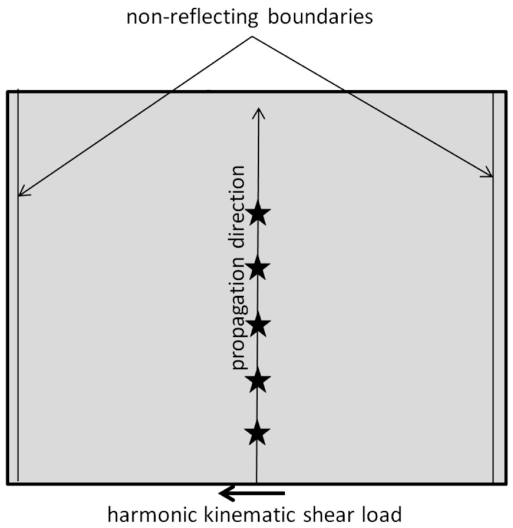
Figure 1. Plane model for analysing propagation of nonlinear S-wave; asterisks denote points of observation.
Mathematics 13 01991 g001
Figure 2. Arrivals of pulses at different points of observation: (a) shear strain; (b) Cauchy shear stress; straight lines correspond to shock wave fronts at ρ0 = µ0 = 1.
Mathematics 13 01991 g002
Figure 3. Energy variation vs. time.
Mathematics 13 01991 g003
Figure 4. (a) Shear tangent modulus vs. strain; (b) shear wave velocity vs. strain.
Mathematics 13 01991 g004
Disclaimer/Publisher’s Note: The statements, opinions and data contained in all publications are solely those of the individual author(s) and contributor(s) and not of MDPI and/or the editor(s). MDPI and/or the editor(s) disclaim responsibility for any injury to people or property resulting from any ideas, methods, instructions or products referred to in the content.