Article

Thermal Investigation of the Magnetised Porous Triangular Fins and Comparative Analysis of Magnetised and Non-Magnetised Triangular Fins

1
Department of Mathematics, University of Malakand, Chakdara Dir(L) 18000, Khyber Pakhtunkhwa, Pakistan
2
Department of Mathematics and Statistics, College of Science, Imam Mohammad Ibn Saud Islamic University (IMSIU), Riyadh 11564, Saudi Arabia
*
Author to whom correspondence should be addressed.
Mathematics 2025, 13(12), 1990; https://doi.org/10.3390/math13121990
Submission received: 8 May 2025 / Revised: 3 June 2025 / Accepted: 10 June 2025 / Published: 16 June 2025
(This article belongs to the Special Issue Computational Methods in Electromagnetics)

Abstract

Fins are extended surfaces designed to increase heat dissipation from hot sources to their surroundings. Heat transfer is improved by utilising fins of different geometrical shapes. Fins are extensively used in automobile parts, solar panels, electrical equipment, computer CPUs, refrigeration systems, and superheaters. Motivated by these applications, this study investigates the incorporation of magnetic fields and porosity into a convective–radiative triangular fin to enhance heat transfer performance. The shooting technique is applied to study thermal profile and efficiency of the fin. It is found that the magnetic number (Hartmann number), porosity, convective, and radiative parameters reduce the thermal profile, while the Peclet number and ambient temperature increase it. Moreover, the efficiency increases with an increase in the magnetic number, porosity, convective, and radiative parameters, whereas it declines with an increase in the Peclet number and ambient temperature. Increasing the magnetic number from 0.1 to 0.7 leads to a 4 % reduction in the temperature profile. Similarly, raising the porosity parameter within the same range results in an approximate 3 % decrease in the thermal profile. An increase in the convective parameter from 0.1 to 0.7 causes about an 8 % decline in the thermal profile, while an elevation in the radiative parameter within the same range reduces it by approximately 2 % . In contrast, enhancing the Peclet number from 0.1 to 0.7 increases the thermal profile by nearly 2 % , and a rise in the ambient temperature within this range leads to an approximate 4 % enhancement in the thermal profile. Magnetised triangular fins are observed to have higher thermal transfer ability and efficiency than non-magnetised triangular fins. It is found that the incorporation of a magnetic field into a triangular fin, in conjunction with the porosity, improves the performance and efficiency of the triangular fin.
MSC:
80A20; 80M50; 78A25; 82D40; 80A23; 78A45

1. Introduction

There are significant applications for improving the heat transfer rate from hot surfaces of a wide range of appliances in technology, industry, and engineering, including refrigerators, air conditioners, aviation engineering, computer equipment, air-cooled aircraft engines, automobile radiators, and electronic systems [1,2]. By optimising extended surfaces, heat is transferred from the hot exterior to adjacent fluids faster. An important factor in the selection of fins is the geometry of the primary surface. Typically, fin profiles are designed based on the cost and ease of manufacture of the materials. In recent years, a lot of research has found a fin profile that transfers heat the fastest for a given fin area [3,4,5]. It has been determined what shape is best, either rectangular, triangular, exponential, circular, or parabolic. Most commonly, rectangular fins are used due to their ease of manufacture. A triangular fin is a good choice since it requires much less material than a rectangular fin for equivalent heat transfer. Parabolic fins, which have higher production costs and a slightly greater rate of per unit volume heat transfer than triangular fins, are avoided [6]. There has therefore been a great deal of attention given to studying the performance of triangular fins found in compressors, computer CPUs, car radiators, air-cooled cylinders, and outer space radiators [7].
The use of porous fins as an improvement to various systems was of great interest to many researchers. In [8], an analysis of Peclet numbers, moving conditions, and thermal exchange parameters is performed to study a convecting longitudinal porous fin’s efficiency. Based on the weighted residual method, [9] demonstrated the regularity of heat transmission through porous fins. They concluded that the fin’s capability can be enhanced by amplifying its porosity and by improving its Darcy, Nusselt, and Rayleigh numbers. According to [10], the least squares method was employed in the study to evaluate the heat distribution across different types of longitudinal fins involving porosity and heat-generating sources. Using the finite volume method, porous fins are used to magnify heat transfer in concentric tubes [11,12].
According to them, thermal conductivity and fin spacing greatly affect heat-transmitting performance. By using DTM, [13] presents a heat transfer model for porous fins assumed to be in motion. In this study, it has been shown that increasing the porosity parameter from 0.1 to 0.5 enhances the temperature of the fin by approximately 6%. Numerical simulations of grey gas radiation’s effects on the heat mass transmission in an annular cavity are presented in [14]. They show that gas radiation alters cavity flow structures, temperatures, and concentration distributions. According to [15], a plate fin-and-tube heat exchanger with slit fins on the ring bridge had numerically simulated thermal transmission properties. The fin pitch of the ring-bridge slit fins was found to be the most critical factor in thermal transmission characteristics, and declining the front slit angle of the sample improves thermal transmission. In [16], a general incremental differential quadrature method was developed for the nonlinear transient analysis of two-dimensional heat transfer in annular fins with continuously varying cross-sections. The study demonstrated that the ratio of the fin length to its inner radius significantly influences the transient thermal response of the annular fins.
It is also important to consider radiative losses from fine surfaces since they are comparable to those caused by natural convection. For this reason, evaluating the performance of conductive, convective, or radiative devices must consider both heat losses at the same time, regardless of their low radiation or convection coefficient. The fin cooled through both convection and radiation has been examined experimentally and numerically in [17]. Based on this analysis, the heat transmitted through radiation comprises about 15–20% of the total transmission. Researchers in [18] found that one-third of the heat is transferred via radiation using cylindrical fins with 0.99 surface emissivity. Rectangular fin effectiveness incorporating radiation was studied using the decomposition method in [19]. Ref. [20] examines the heat transmission properties of a wavy fin under radiation combined with convection. In this study, wavy and rectangular fins showed decreased thermal distribution with the enhancement in convection and radiation. According to [21], approximately 10 to 20 percent of all thermal losses result from the radiation mechanism from polished aluminium fins.
Studies [22,23,24] have examined the role of magnetic fields in porous fin heat transmission. Further improvements were made using the Adomian decomposition method [25]. Furthermore, the finite volume method was employed in [26] to investigate the significant influence of the magnetism on the porous fin’s performance for heat transfer. Fins were found to be more heat transferable when the magnetism was enhanced. Afterwards, the heat generation along with the magnetic field was added to the longitudinal fins, and the behaviour of the fin was analysed using an iterative method [27]. A study was conducted on the magnetohydrodynamic effect on fins in various circumstances in [28].
Several studies have been conducted on triangular fins in the literature. In a triangular structure, heat transfer has been numerically studied by considering the elastic effect of flow, which enhances the fin’s heat dissipation [29]. ADM (Adomian decomposition method) was used to investigate the impact of humidity levels on the efficiency of triangular fins for heat mass transfer [30]. They studied the comparison with the previous model and noticed significant differences. Also, found wet fins have better fin performance. Thermal performance has been investigated in a CPU’s mainboard heat sink with a micropin fin of triangular geometry [31]. They visualised that the Nusselt number grows with increased air flow velocity, leading to a greater extraction of heat from CPUs. A heat transfer investigation of a moving porous triangular fin with a heat generation source is conducted in [32]. According to their study, factors such as porosity, radiation, and convection all contribute to growth in heat transfer. In [33], a partial filling approach is utilised, featuring a heat sink designed to cool a protruding electronic component (EC) mounted on a metal fin. The study employs the enthalpy-porosity method in conjunction with the thermal equilibrium model. Results indicate that increasing the filling ratio of aluminium (Al) foam enhances the heat sink’s efficiency, leading to a temperature reduction of 15.85 °C in the electronic component (EC).
In traditional fin designs, thermal management is mainly determined by geometric shape, material properties, and surface area. However, there is increasingly a need to explore innovative strategies to improve heat transfer efficiency in modern applications. Incorporating magnetic fields and porosity into fin structures is one promising approach. Magnetic fields influence the thermal conductivity of materials, potentially improving heat transfer efficiency. Meanwhile, porosity can further increase surface area and improve fluid interaction within the fin, potentially improving convective heat transfer.
The triangular fins could be used in cooling solutions for high-performance computers or electric vehicle batteries, where temperature control is crucial to preventing overheating. Triangular fins are also useful in improving heat transmission and are applicable to various technological systems such as automobile radiators, condensers, evaporators, turbine blades, solar systems and refrigeration systems. They are also used in heat sinks for cooling CPUs and power transistors. In traditional fin designs, thermal management is mainly determined by geometric shape, material properties, and surface area. However, there is increasingly a need to explore innovative strategies to improve heat transfer efficiency in modern applications. Incorporating magnetic fields and porosity into fin structures is one promising approach. Magnetic fields influence the thermal conductivity of materials, potentially improving heat transfer efficiency. Meanwhile, porosity can further increase surface area and improve fluid interaction within the fin, potentially improving convective heat transfer. To explore these applications, a magnetised, porous triangular fin was considered. By applying dimensionless parameters, the governing equation is made dimensionless, and a numerical result is generated using the shooting technique and analysed for the influence of the considered parameters on triangular fins.

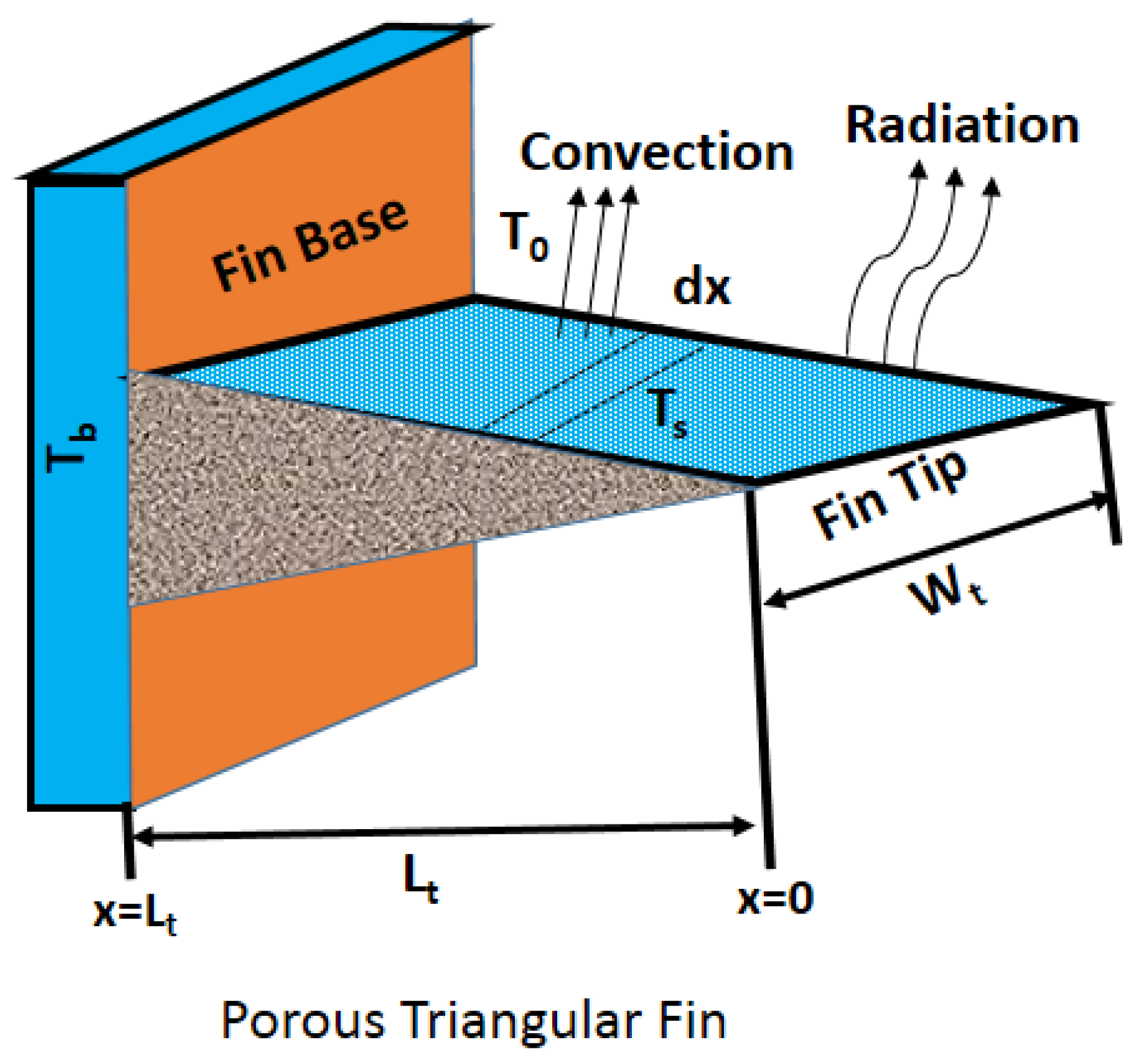
2. Mathematical Formulation

Consider heat transfer in a convective–radiative, porous, and magnetised triangular fin of length L t , area A t , and thickness t a , as shown in Figure 1. The considered parameters in the model are as follows: ρ is density, ε is the emissivity, h is the heat transfer coefficient, T represents temperature distribution, σ denotes Stefan–Boltzmann constant, C p is the specific heat, k indicates the thermal conductivity, T 0 is the ambient temperature, T b is base temperature, and T s f is the surface temperature. The fin is considered movable with velocity U m , and x represents the distance from the fin’s base. In the present study, the following thermal properties of the considered fin are assumed:
  • The thermal conductivity and thermal diffusivity of the fin material, as well as the convective heat transfer coefficient, are assumed constant.
  • The porous medium is homogeneous, isotropic, and fully saturated with a single-phase fluid.
  • The temperature variation within the fin is considered to be one-dimensional and varies along the length of the fin.
  • The Darcy model is used to simulate fluid flow through porous media.
Figure 1. Diagram of magnetised triangular fin.
Mathematics 13 01990 g001
The energy equation is given by [26,32]
q x ˜ q x ˜ + d q x ˜ d x d x + U m A t C p ρ d q x ˜ d x d x C p m ˜ [ T T o ] J c × J c σ d x h P t ( 1 ψ ) [ T T o ] d x σ P t ε T 4 T s f 4 d x = 0 .
considering d x 0 , then Equation (2) becomes
d q x ˜ d x + U m A t C p ρ d q x ˜ d x d x C p m ˜ [ T T o ] J c × J c σ d x h P t ( 1 ψ ) [ T T o ] d x σ P t ε T 4 T s f 4 d x = 0 .
where J c indicates the conduction current intensity which is given as
J c = σ ( E + B × V ) .
J t denotes the total current intensity and is defined as
J t = σ V + J c ,
m ¯ = ρ W t ψ x v w .
where ψ is the fin’s porosity. As ψ ranges between 0 and 1, solid medium has ψ = 0 , and when ψ = 1 , there is no solid region. Here, the Darcy formula is given as [34]
v w = β K g ν ( T T o ) .
The Fourier’s law of heat conduction is given as [35]
q x ˜ = k A t d T d x .
where k denotes thermal conductivity.
By utilising Equations (5)–(7) in Equation (2), we get
d d x A t d T d x + C p ρ U t k A t d T d x β K t a g [ T T o ] k ν J c × J c σ k h P t ( 1 ψ ) k [ T T o ] P t ε σ k T 4 T s f 4 = 0 ,
J c × J c σ = σ u t 2 B 0 2 .
where B 0 in the problem represents the magnetic field intensity.
Putting Equation (9) in Equation (8), we get
d d x A t d T d x + C p ρ U t k A t d T d x β K t a g [ T T o ] k ν σ u 2 B 0 2 k [ T T 0 ] h P t ( 1 ψ ) k [ T T o ] P t ε σ k T 4 T s f 4 = 0 .
Using the following adiabatic BCs,
A t x = L , T = T b , and x = 0 , d T d x = 0 .
Converting the equations to non-dimensional form, we have
X = x L t , θ = T T b , θ s f = T s f T b , θ a = T 0 T b , N c = h P t L t 2 A t k , H = σ B 0 2 u t 2 k t a N r = ϵ σ P t L t 2 T b 3 k A t , R a = β g t a K [ T b T 0 ] λ ν k , P e = U t P t L t k λ ,
Equations (10) and (11) become dimensionless using the above parameters
X d 2 θ d X 2 + ( 1 + X P e ) d θ d X R a θ ( X ) 2 H θ ( X ) N c [ θ θ a ] N r θ 4 θ s f 4 = 0 ,
with boundary conditions
X = 1 , θ = 1 , and X = 0 , d θ d X = 0 .
where ( H ) denotes the magnetic number (Hartmann number), ( N r ) represents the radiation parameter, ( N c ) represents the convection–conduction parameter, ( P e ) indicates the Peclet number, and ( R a ) indicates the Rayleigh number (porosity parameter).
In the absence of a magnetic field, taking magnetic number (Hartmann number) H = 0 , Equation (12) becomes
X d 2 θ d X 2 + ( 1 + X P e ) d θ d X R a θ ( X ) 2 N c [ θ θ a ] N r θ 4 θ s f 4 = 0 ,
Equation (14) exhibits the temperature profile for non-magnetised triangular fins.
Fin efficiency describes the decrease in temperature potential between the surrounding area and the fin. Efficiency is denoted by η and is calculated by dividing the total heat transport by the maximum heat transport of the fin. The efficiency of a triangular fin is written as [36]
η = θ ( 1 ) N c 2 ( 1 θ a ) .
Equations (12) and (18) demonstrate that the temperature profile and efficiency depend on various parameters, which include the convection ( N c ) , Hartmann number ( H ) , radiation ( N r ) , Rayleigh number ( R a ) , and Peclet number ( P e ) .

3. The Shooting Method

The shooting method is used to compute the model. The shooting technique converts the boundary value problems into initial value problems. Generally, we attempt various trajectory paths until the optimal boundary value is obtained.
Firstly, we have to introduce the Dirichlet BVP for linear differential equations in the second order.
d 2 U d W 2 = G ( W ) d U d W + R ( W ) U + H ( W ) subject to U ( a ) = ψ , z ( b ) = ξ ,
on the interval [ ψ , ξ ] .
This BVP is usually computed by combining the functions ψ ( W ) and ξ ( W ) , which are IVP solutions.
U ( t ) = φ ( t ) + ξ φ ( b ) χ ( b ) · χ ( t ) ,
Here, the IVP solution is represented by φ ( t ) .
d 2 φ d t 2 = G ( t ) d φ d t + s ( t ) φ + v ( t ) , φ ( a ) = ψ , d φ ( a ) d t = 0 ,
and another initial value problem solution is Ω ( t )
d 2 Ω d t 2 = G ( t ) d Ω d t + s ( t ) Ω + v ( t ) , Ω ( a ) = ψ , d Ω ( a ) d t = 0 ,

4. Application of Shooting Method

Consider the transformed second-order differential equation
d 2 θ d X 2 = P e d θ d X + 1 X d θ d X + R a θ 2 + H θ + N c [ θ θ a ] + N r θ 4 θ s f 4 .
First, convert the equation into a system of first-order equations by assuming new variables.
Let
y 1 = θ , y 2 = d θ d X .
The considered Equation (12) becomes the system of first-order ODEs
d y 2 d X = P e y 2 + 1 X y 2 + R a y 1 2 + H y 1 + N C [ y 1 θ a ] + N r y 1 4 θ s f 4 .
Now, we solve this system on the interval X ϵ [ 0 , 1 ] with boundary conditions:
y 1 ( 1 ) = 1 , y 2 ( 0 ) = 0 .
Then, guess the initial value y 2 ( 1 ) = κ . After that, integrate the system from X = 0 to X = 1 , and iterate the system until the boundary condition at the tip y 2 ( 0 ) = 0 is satisfied.

5. Results and Discussion

In this article, we investigate the temperature profile and triangular fin’s efficiency η of the magnetised convective–radiative triangular fins. The temperature profile θ ( X ) of considered parameters is illustrated in Figure 2, Figure 3 and Figure 4.
Figure 2a demonstrates the temperature profile behaviour versus the length of the magnetised triangular fin under the impact of the magnetic number or Hartmann number H. Physically, increasing the magnetic number (Hartmann number) results in a reduced temperature profile, which causes more heat to escape from the triangular fin. Improvements in the magnetic number or Hartmann number increase the magnetic field strength, facilitating thermal convection. Thus, the temperature profile declines.
Figure 2b shows how the temperature profile of a magnetised triangular fin changes in response to raising the radiative parameter from 0.1 to 0.7 . Raising the radiative parameter clearly shows a decline in temperature. Physically, heat is transported off fin surfaces by radiation, resulting in a lower temperature profile. It is beneficial to raise the radiative parameter in order to improve the thermal exchange.
The temperature profile behaviour is shown in Figure 3a,b based on the convection parameter N c and the Raleigh number or porosity parameter R a . Figure 3a depicts the effect of escalating the convection parameter from 0.1 to 0.7 on the triangular fin temperature profile. In response to the convection impact around the fin, more heat is lost, resulting in it becoming colder. Thermal transport at the surface is therefore increased by upgrading the convection parameter.
The temperature profile behaviour of a triangular fin is due to its Raleigh number or porosity parameter R a , shown in Figure 3b. An increase in the Raleigh number (porosity parameter) from 0.1 to 0.7 results in significant reductions in the fin’s temperature, leading to increased heat transmission. Physically, when the Rayleigh number is low, heat transfer via conduction dominates, and the flow remains stable and non-turbulent. The system behaves similarly to a simple conduction in this case. As the Rayleigh number increases, buoyancy forces overcome viscous damping, resulting in turbulent convection. Convection becomes more pronounced as the Rayleigh number increases, creating turbulence, which increases heat transfer.
Figure 4a illustrates how changing the Peclet number from 0.1 to 0.7 improves the temperature profile. As Peclet numbers increase, the triangular fin’s speed becomes higher, and the time of interaction with the surrounding surface decreases, increasing the temperature. Physically, convection dominates conduction when the Peclet number is large. As a result, the fluid’s velocity is high compared to the thermal diffusion, and the heat is carried away quickly.
Similarly, Figure 4b shows that the temperature profile steps up by escalating θ a from 0.3 to 0.7 . This raises fin surface temperature due to an adverse effect on convective heat loss. Hence, lowering θ a accelerates fin cooling.
Increasing the magnetic number (Hartmann number) from 0.1 to 0.7 reduces the temperature profile by about 4 % , as observed in Figure 2a. Upgrading the radiative parameter N r from 0.1 to 0.7 reduces the temperature profile by approximately 2 % as shown in Figure 2b. A 3 % reduction in the temperature profile is obtained by escalating the Raleigh number R a from 0.1 to 0.7 , as in Figure 3b.
The efficiency ( η ) of the triangular fin is studied as a function of the magnetic number (Hartmann number) between 0 and 1 in Figure 5 and Figure 6. These figures exhibit that efficiency grows with rising magnetic number (Hartmann number) from 0 and 1. A gradual enhancement in the efficiency occurs when the values of N C , N r , and R a rise from 0.1 to 0.7 , as illustrated in Figure 5a,b and Figure 6b; however, Figure 6a exhibits that as P e steps up from 0.1 to 0.7 , the efficiency continuously decreases.
In addition, Figure 7 compares the efficiency η with the Raleigh number (porosity parameter) R a , which varies from 0 to 1. The aforementioned figures demonstrate that triangular fin efficiency increases rapidly with increased R a . A further improvement in fin efficiency occurs when H is raised from 0.1 to 0.7 , as depicted in Figure 7a. In contrast, the rise of θ e from 0.1 to 0.7 is at odds with the efficiency as shown in Figure 7b. The above-mentioned behaviour of magnetised triangular fins with radiation led to the conclusion that triangular fins coupled with magnetic fields showed higher heat exchange, efficiency, and economic benefits.

6. Comparative Numerical Analysis

The temperature profile and efficiency η of the magnetised triangular fins are compared with non-magnetised triangular fins, as illustrated in Figure 8 and Figure 9.
The results in Figure 8 exhibited that the temperature profile of the magnetised triangular fins is steeper than non-magnetised triangular fins. Thus, magnetism enhances the heat transmission from the fin. Also, the influence of increasing radiation parameters and Raleigh numbers (porosity parameters) sharply declines the temperature of both magnetised and non-magnetised triangular fins.
From Figure 9, it is noticed that the efficiency of magnetised triangular fins is higher than that of non-magnetised triangular fins. Moreover, the efficiency of both magnetised and non-magnetised triangular fins rises with increasing Rayleigh number (porosity parameter) and radiation parameter.

7. Comparison with Experimental Results

The results were validated with the published experimental results. According to experimental analysis [37], fin porosity influences heat transfer. The heat dissipation rate increases by 20 % to 70 % as the perforations increase from ( 24 to 60 ) . Further increases in perforation numbers result in reduced fin heat dissipation. The use of annular porous fins attached to a heated vertical cylinder was investigated experimentally in [38]. The heat transfer coefficient increased by 7.9 % with a 10 mm thick fin and by 131 % with a porous layer. According to this study, porous fins enhanced heat transfer significantly. Experimental evaluation of the thermal performance of an annular fin-shell tube storage system using magnetic fluid is presented in [39]. The efficiency of an annular fin geometry increases by 20 % when magnetic fluid is added. A thin layer of magnetic fluid was maintained on the fins by the magnetic ring of a small magnet with a thickness of 1 mm and a diameter of 2.5 mm. It is found that a layer of magnetic fluid placed on top of a fin significantly enhances its relative heat transfer rate by 35 % , resulting in a significant improvement in performance. Further, there is a sharp decline in temperature distribution along the fin’s length. This numerical study illustrates a similar trend to the experimental study.

8. Conclusions

This article investigates the thermal performance of porous, magnetised triangular fins. The governing equations of the model are nondimensionalised. The resulting nonlinear differential equations, along with the prescribed boundary conditions, are numerically solved using the shooting method to analyse the temperature distribution and efficiency of the fin model. The obtained results are presented and analysed graphically. The results reveal that the temperature profile decreases while heat transfer from the fin increases with a higher Rayleigh number (porosity parameter), Hartmann number (magnetic parameter), radiative parameter, and convective parameter. In contrast, increasing ambient temperature and Peclet number lead to a higher temperature profile and reduced heat transfer from the fin. Efficiency improves with a rising Rayleigh number, Hartmann number, and radiative and convective parameters, but declines as the Peclet number and ambient temperature increase. This study also compares magnetised triangular fins and non-magnetised triangular fins in terms of temperature profile and efficiency. Compared to non-magnetised fins, magnetised triangular fins exhibit a lower temperature profile and higher thermal efficiency. The findings are validated through comparison with existing experimental data. It was concluded from this study that a porous triangular fin combined with a radiative parameter has better thermal performance and effectiveness than a non-magnetic triangular fin when incorporating a magnetic effect into a porous triangular fin.

Author Contributions

Conceptualization, M.B.J.; Methodology, S.U.; Software, G.A.; Formal analysis, S.U.; Investigation, S.U.; Writing—original draft, M.B.J.; Writing—review & editing, M.B.J.; Project administration, G.A.; Funding acquisition, G.A. All authors have read and agreed to the published version of the manuscript.

Funding

This work was supported and funded by the deanship of scientific research at Imam Mohammad Ibn Saud Islamic University (IMSIU) (grant number IMSIU-DDRSP2503).

Data Availability Statement

The original contributions presented in this study are included in the article. Further inquiries can be directed to the corresponding authors.

Conflicts of Interest

The authors declare no conflicts of interest.

Nomenclature

P e Peclet number L t Fins length
N r Radiation parameter ν Kinematics viscosity
q x ˜ Heat transfer rateTFin temperature ( K )
β Volumetric thermal expansion coefficient v w fluid velocity
ψ Fin’s porosityHHartmann number
VVoltage η Fin efficiency
ρ Density of material (kg/m3)XDimensionless distance
B 0 Magnetic field intensity P r Dimensional distance
N c Convection parameter C p Specific heat coefficient
A t Area of fin’s surface (m2) I V P Initial value problem
T s f Dimensional surface temperaturexDimensional distance
BMagnetic Induction θ ( X ) Dimensionless temperature
D a Darcy number m ¯ Mass flow rate
P e Peclet numberhConvective heat coefficient
ε Emissivity t a Fin’s thickness
R a Rayleigh number C p Specific heat coefficient
J t d Total current density T o dimensional ambient temperature
kThermal conductivity number                     U m    Fin’s moving speed
B C s Boundary conditions σ Stefan–Boltzmann constant (W/m2 K4)
λ Diffusivity J c d Conduction current density
T b Fin base temperature u t Axial velocity
W t Fin’s widthgGravity constant (ms−2)
EElectric fieldKFin permeability
θ s f Dimensionless surface temperature θ a Non-dimensional ambient temperature

References

  1. Kraus, A.D.; Aziz, A.; Welty, J. Extended Surface Heat Transfer; John Wiley, Inc.: New York, NY, USA, 2001. [Google Scholar]
  2. Kalpakjian, S. Manufacturing Engineering and Technology; Pearson Education: Bengaluru, India, 2001. [Google Scholar]
  3. Aziz, A. Optimum dimensions of extended surfaces operating in a convective environment. Appl. Mech. Rev. 1992, 45, 155–173. [Google Scholar] [CrossRef]
  4. Duffin, R. A variational problem relating to cooling fins. J. Math. Mech. 1959, 8, 47–56. [Google Scholar] [CrossRef]
  5. Kundu, B.; Das, P.K. Optimum profile of thin fins with volumetric heat generation—A unified approach. ASME J. Heat Trans. 2005, 127, 945–948. [Google Scholar] [CrossRef]
  6. Kraus, A.D. Sixty-five years of extended surface technology (1922–1987). Appl. Mech. Rev. 1988, 41, 321–364. [Google Scholar] [CrossRef]
  7. Mirapalli, S.; Kishore, P.S. Heat Transfer Analysis on a Triangular Fin. Int. J. Eng. Trends. Tech. 2015, 19, 279–284. [Google Scholar] [CrossRef]
  8. Dogonchi, A.S.; Ganji, D.D. Convection—radiation heat transfer study of moving fin with temperature-dependent thermal conductivity, heat transfer coefficient and heat generation. Appl. Therm. Eng. 2016, 103, 705–712. [Google Scholar] [CrossRef]
  9. Sobamowo, M.G. Thermal analysis of longitudinal fin with temperature-dependent properties and internal heat generation using Galerkin’s method of weighted residual. Appl. Therm. Eng. 2016, 99, 1316–1330. [Google Scholar] [CrossRef]
  10. Shateri, A.R.; Salahshour, B. Comprehensive thermal performance of convection—radiation longitudinal porous fins with various profiles and multiple nonlinearities. Int. J. Mech. Sci. 2018, 136, 252–263. [Google Scholar] [CrossRef]
  11. Logesh, K.; Arunraj, R.; Govindan, S.; Thangaraj, M.; Yuvashree, G.K. Numerical investigation on the possibility of heat transfer enhancement using reduced weight fin configuration. Int. J. Ambient Energy 2018, 41, 142–145. [Google Scholar] [CrossRef]
  12. Gao, S.; Ma, T.; Zhou, N.; Feng, J.; Huayan, P.; Luo, J.; Pennacchi, P.; Chu, F.; Han, Q. Extremely compact and lightweight triboelectric nanogenerator for spacecraft flywheel system health monitoring. Nano Energy 2024, 122, 109330. [Google Scholar] [CrossRef]
  13. Din, Z.U.; Ali, A.; Khan, Z.A.; Zaman, G. Heat transfer analysis: Convective-radiative moving exponential porous fins with internal heat generation. Math. Biosci. Eng. 2022, 19, 11491–11511. [Google Scholar] [CrossRef] [PubMed]
  14. Boussandel, A.; Laouar-Meftah, S.; Retiel, N. Numerical analysis of gray gas radiation effects on heat and mass transfer in an annular cavity. Therm. Sci. 2024, 28, 114–124. [Google Scholar] [CrossRef]
  15. Wang, Z.; Ouyang, X. Numerical simulation of heat transfer and flow characteristics for plate fin-and-tube heat exchanger with ring-bridge slit fins. Therm. Sci. 2023, 28, 86–96. [Google Scholar] [CrossRef]
  16. Malekzadeh, P.; Rahideh, H. IDQ two-dimensional nonlinear transient heat transfer analysis of variable section annular fins. Energy Convers. Manag. 2007, 48, 269–276. [Google Scholar] [CrossRef]
  17. Mueller, J.D.; Abu-Mulaweh, H.I. Prediction of the temperature in a fin cooled by natural convection and radiation. Appl. Therm. Eng. 2006, 26, 1662–1668. [Google Scholar] [CrossRef]
  18. Edwards, J.A.; Chaddock, J.B. An experimental investigation of the radiation and free convection heat transfer from a cylindrical disk extended surface. Trans. Am. Soc. Heat Refrig. Air-Conditioning Eng. 1963, 69, 313–322. [Google Scholar]
  19. Arslanturk, C. Optimum design of space radiators with temperature-dependent thermal conductivity. Appl. Therm. Eng. 2006, 26, 1149–1157. [Google Scholar] [CrossRef]
  20. Prakash, S.B.; Chandan, K.; Karthik, K.; Devanathan, S.; Kumar, R.V.; Nagaraja, K.V.; Prasannakumara, B.C. Investigation of the thermal analysis of a wavy fin with radiation impact: An application of extreme learning machine. Phys. Scr. 2023, 99, 015225. [Google Scholar] [CrossRef]
  21. Chaddock, J.B. Free convection heat transfer from vertical fin arrays. J. Am. Soc. Heat Refrig. Air-Cond. Eng. 1970, 12, 53–60. [Google Scholar]
  22. Hoshyar, H.A.; Ganji, D.D.; Majidian, A.R. Least square method for porous fin in the presence of uniform magnetic field. J. Appl. Fluid Mech. 2016, 9, 661–668. [Google Scholar] [CrossRef]
  23. Li, X.; Yu, P.; Niu, X.; Yamaguchi, H.; Li, D. Non-contact manipulation of nonmagnetic materials by using a uniform magnetic field: Experiment and simulation. J. Magn. Magn. Mater. 2020, 497, 165957. [Google Scholar] [CrossRef]
  24. Dong, Z.Q.; Li, X.; Yamaguchi, H.; Yu, P. Magnetic field effect on the sedimentation process of two non-magnetic particles inside a ferrofluid. J. Magn. Magn. Mater. 2024, 589, 171501. [Google Scholar] [CrossRef]
  25. Patel, T.; Meher, R. Thermal Analysis of the porous fin with uniform magnetic field using Adomian decomposition Sumudu transform method. Nonlinear Eng. 2017, 6, 191–200. [Google Scholar] [CrossRef]
  26. Oguntala, G.; Abd-Alhameed, R.; Ngala, M. Transient thermal analysis and optimization of convective-radiative porous fin under the influence of magnetic field for efficient microprocessor cooling. Int. J. Therm. Sci. 2019, 145, 106019. [Google Scholar] [CrossRef]
  27. Oguntala, G.; Sobamowo, G.; Abd-Alhameed, R.; Jones, S. Efficient iterative method for investigation of the convective—radiative porous fin with internal heat generation under a uniform magnetic field. Int. J. Appl. Comp. Math. 2019, 5, 1–13. [Google Scholar] [CrossRef]
  28. Sreedevi, P.; Reddy, P.S. Effect of SWCNTs and MWCNTs Maxwell MHD nanofluid flow between two stretchable rotating disks under convective boundary conditions. Heat Transf.—Asian Res. 2019, 48, 4105–4132. [Google Scholar] [CrossRef]
  29. Hsiao, K.L.; Hsu, C.H. Conjugate heat transfer of mixed convection for visco-elastic fluid past a triangular fin. Nonlinear Anal Real World Appl. 2009, 10, 130–143. [Google Scholar] [CrossRef]
  30. Kundu, B.; Barman, D.; Debnath, S. An analytical approach for predicting fin performance of triangular fins subject to simultaneous heat and mass transfer. J. Mol. Liq. 2008, 31, 1113–1120. [Google Scholar] [CrossRef]
  31. Alam, M.W.; Bhattacharyya, S.; Souayeh, B.; Dey, K.; Hammami, F.; Rahimi-Gorji, M.; Biswas, R. CPU heat sink cooling by triangular shape micro-pin-fin: Numerical study. Int. Commun. Heat Mass Transf. 2020, 112, 104455. [Google Scholar] [CrossRef]
  32. Ullah, I.; Ullah, S.; Ali, A.; Shah, S.I.; Weera, W.; Alam, M.M. Heat transfer analysis from moving convection-radiative triangular porous fin exposed to heat generation. Case Stud. Therm. Eng. 2022, 38, 102177. [Google Scholar] [CrossRef]
  33. Afaynou, I.; Faraji, H.; Choukairy, K.; Khallaki, K.; Akrour, D. Effectiveness of a PCM-based heat sink with partially filled metal foam for thermal management of electronics. Int. J. Heat Mass Transf. 2024, 235, 126196. [Google Scholar] [CrossRef]
  34. Das, R.; Ooi, K.T. Predicting multiple combinations of parameters for designing a porous fin subjected to a given temperature requirement. Energy Convers. Manag. 2013, 66, 211–219. [Google Scholar] [CrossRef]
  35. Waseem, W.; Sulaiman, M.; Islam, S.; Kumam, P.; Nawaz, R.; Raja, M.A.Z.; Farooq, M.; Shoaib, M. A study of changes in temperature profile of porous fin model using cuckoo search algorithm. Alex. Eng. J. 2020, 59, 11–24. [Google Scholar] [CrossRef]
  36. Turkyilmazoglu, M. Efficiency of heat and mass transfer in fully wet porous fins: Exponential fins versus straight fins. Int. J. Refrig. 2014, 46, 158–164. [Google Scholar] [CrossRef]
  37. Prasad, L.; Kumar, A.; Tewari, S. An experimental study of heat transfer enhancement in the perforated rectangular fin. J. Integr. Sci. Technol. 2016, 4, 5–9. [Google Scholar]
  38. Kiwan, S.; Alwan, H.; Abdelal, N. An experimental investigation of the natural convection heat transfer from a vertical cylinder using porous fins. App. Therm. Eng. 2020, 179, 115673. [Google Scholar] [CrossRef]
  39. Pathak, S.; Jain, K.; Kumar, P.; Wang, X.; Pant, R.P. Improved thermal performance of annular fin-shell tube storage system using magnetic fluid. Appl. Energy 2019, 239, 1524–1535. [Google Scholar] [CrossRef]
Figure 2. Thermal field evaluation of considered triangular fin (a) The effect of Hartmann number H (b) The effect of radiation parameter N r .
Mathematics 13 01990 g002
Figure 3. Thermal field evaluation of considered triangular fin (a) The effect of convection parameter N c (b) The effect of the Raleigh number or porosity parameter R a .
Mathematics 13 01990 g003
Figure 4. Thermal field evaluation of considered triangular fin (a) The effect of the Peclet number P e (b) The effect of ambient temperature θ a .
Mathematics 13 01990 g004
Figure 5. Efficiency evaluation of magnetised triangular fin (a) The effect of convection parameter N c (b) The effect of radiation parameter N r .
Mathematics 13 01990 g005
Figure 6. Efficiency evaluation of magnetised triangular fin (a) The effect of the Peclet number P e (b) The effect of the Raleigh number (porosity parameter) R a .
Mathematics 13 01990 g006
Figure 7. Efficiency evaluation of magnetised triangular fin (a) The effect of the magnetic number (Hartmann number) H (b) The effect of the ambient temperature θ a .
Mathematics 13 01990 g007
Figure 8. Temperature distribution for magnetised triangular fin and non-magnetised triangular fin (a) The effect of radiation parameter N r (b) The effect of the Rayleigh number (porosity parameter) R a .
Mathematics 13 01990 g008
Figure 9. Efficiency for magnetised triangular fin and non-magnetised triangular fin (a) The effect of the Rayleigh number (porosity parameter) R a (b) The effect of radiation parameter N r .
Mathematics 13 01990 g009
Disclaimer/Publisher’s Note: The statements, opinions and data contained in all publications are solely those of the individual author(s) and contributor(s) and not of MDPI and/or the editor(s). MDPI and/or the editor(s) disclaim responsibility for any injury to people or property resulting from any ideas, methods, instructions or products referred to in the content.

