Article

Analysis of MCP-Distributed Jammers and 3D Beam-Width Variations for UAV-Assisted C-V2X Millimeter-Wave Communications

1
Department of Computer Engineering, Gachon University, Seongnam-si 13120, Republic of Korea
2
School of Computer Science and Engineering, Yeungnam University, Gyeongsan-si 38541, Republic of Korea
*
Authors to whom correspondence should be addressed.
These authors contributed equally to this work.
Mathematics 2025, 13(10), 1665; https://doi.org/10.3390/math13101665
Submission received: 22 April 2025 / Revised: 15 May 2025 / Accepted: 17 May 2025 / Published: 19 May 2025
(This article belongs to the Section D1: Probability and Statistics)

Abstract

:
Jamming devices introduce unwanted signals into the network to disrupt primary communications. The effectiveness of these jamming signals mainly depends on the number and distribution of the jammers. The impact of clustered jamming has not been investigated previously for an unmanned aerial vehicle (UAV)-assisted cellular-vehicle-to-everything (C-V2X) communications by considering multiple roads in the given region. Also, exploiting three-dimensional (3D) beam-width variations for a millimeter waveband antenna in the presence of jamming for vehicular node (V-N) links has not been evaluated, which influences the UAV-assisted C-V2X system’s performance. The novelty of this paper resides in analyzing the impact of clustered jamming for UAV-assisted C-V2X networks and quantifying the effects of fluctuating antenna 3D beam width on the V-N performance by exploiting millimeter waves. To this end, we derive the analytical expressions for coverage of a typical V-N linked with a line-of-sight (LOS) UAV, non-LOS UAV, macro base station (MBS), and recipient V-N for UAV-assisted C-V2X networks by exploiting beam-width variations in the presence of jammers. The results show network performance in terms of coverage and spectral efficiencies by setting V-Ns equal to 3 km−2, MBSs equal to 3 km−2, and UAVs equal to 6 km−2. The findings indicate that the performance of millimeter waveband UAV-assisted C-V2X communications is decreased by introducing clustered jamming in the given region. Specifically, the coverage performance of the network decreases by 25.5% at −10 dB SIR threshold in the presence of clustered jammers. The performance further declines by increasing variations in the antenna 3D beam width. Therefore, network designers must focus on considering advanced counter-jamming techniques when jamming signals, along with the beam-width fluctuations, are anticipated in vehicular networks.

1. Introduction

Jamming is a phenomenon where undesired jamming signals disrupt a desired legitimate communication. The intensity of jamming cannot only be characterized by the power or the number of jamming devices, but also by the distribution of jammers. Clustered jamming refers to the jamming signals exploiting the clustered distribution of jamming devices [1]. Conventionally clustered jamming consists of multiple clusters of jammers, and their distribution is modeled using the Matern cluster process (MCP). MCP consists of parent nodes forming the cluster centers and the child nodes or the jamming devices [2,3]. The child nodes or the jamming devices are distributed using uniform distribution inside the cluster of a circular radius. The jamming clusters and the jammers in a cluster are Poisson random variables. The total number of jamming devices in the considered area is given by the total number of jammers in all the clusters.
Jamming signals influence the effectiveness of vehicle-to-everything (V2X) communication in terms of vehicle equipment’s coverage and spectral efficiency (SE) [4,5]. V2X connectivity is critical for improving road safety and enabling vehicular autonomy. It provides safety-related features, including disaster cautions, pre-crash sensory notices, and automatic crash updates, that are critical for minimizing fatalities and enhancing global highway safety. Furthermore, V2X enables sophisticated autonomy capabilities such as vehicular platooning, joint collision minimization via vehicular communication, and automatic overtake for effective and reliable lane changes [6,7]. Yet, jamming attempts may drastically influence such important features by interfering wirelessly, resulting in extended latency or missed signals, elevated accident potential hazards, and reduced productivity of vehicular technologies. Thus, analyzing the impact of jamming becomes essential in investigating vehicular network performance.
To meet the severe requirements of self-driving applications, millimeter-wave band connection is a vital requirement for unmanned aerial vehicle (UAV)-assisted cellular-V2X (C-V2X) systems. Beam orientation is critical in the millimeter wave range to avoid propagation losses as well as to preserve a stable network. For aerial networks, line-of-sight (LOS) path information is critical for introducing beams, especially for flying links [8]. To gather and send data in the millimeter wave frequency band, directed beams must be aligned between sources and terminals. Beam tracing is the continuous monitoring of a beam targeting a subject that is moving [9]. Thus, detecting the beam alignment of automobiles that move with variable speeds is a greater challenge than detecting objects that are still. Beam tracing gets more difficult when the three-dimensional (3D) antenna’s radiating beam varies due to wind, air pressure, or noise from the regulating motors. As a result, it is critical to quantify the variations of the UAVs’ 3D radio beam, particularly for UAV-assisted C-V2X transmissions.
Vehicular nodes (V-Ns), comprising vehicles, pedestrians, and roadside units (RSUs), can interact with each other either directly or using a sharing network layout [7,10]. The third-generation partnership project (3GPP), Release 16 enables V-Ns to communicate directly via the PC5 (sidelink) connection as well as collaboratively via the Uu connection. The shared technique design uses independent downstream links and upload links for the macro base station (MBS) or UAV. Normally, for C-V2X connectivity, the V-N’s upward connectivity permits transfer to the telecom tower-mounted station, which might be an MBS (in V2M link) [11]. In contrast, for UAV-assisted C-V2X connectivity, the V-N’s upstream link enables dissemination to the LOS low-altitude platform (LAP) (in V2L link) or non-LOS (NLOS) LAP (in V2N link). The upstream link between the V-N and the MBS or LOS/NLOS-LAP uses a distinct spectrum range for communication, whereas the downstream link between the MBS or LOS/NLOS-LAP and V-N uses a distinct spectrum range. The V-N’s upstream connectivity for UAV-assisted C-V2X links uses shared channel transmissions with MBS, LOS-LAP, or NLOS-LAP via the Uu link. In contrast, transmission in the direct method for UAV-assisted C-V2X links connects transmitting V-N to a receiving V-N via a sidelink platform. Jamming signals as well as 3D beam-width variations can seriously degrade a UAV-assisted C-V2X framework’s efficiency that uses shared V-N to V-N messages (including LOS-LAP, NLOS-LAP, and MBS) or direct V-N to V-N messages; thus, assessing the influence of jamming along with varying beam-width position while examining the reliability associated with a VN in vehicular networks is of vital importance.

1.1. Related Works

UAV-assisted C-V2X communications can support both UAVs and base stations to exploit vehicular communications. This is achieved via vehicle-to-vehicle (V2V) direct-mode communications using PC5 or side-link interface and vehicle-to-infrastructure (V2I) shared-mode communications using the Uu interface. In [12], various propagation models are presented for the direct-mode connectivity that typically considers V-N to V-N transmissions, e.g., the transmission of a vehicle to nearby RSUs, the transmission of a vehicle to nearby pedestrians, or V2V transmissions, as well as for the shared-mode connectivity that considers V-N to cellular base station transmissions or the transmission of V-N to LOS UAV or NLOS UAV. However, the presence of jamming devices in UAV-assisted C-V2X communications can disrupt the safety-based services as well as the autonomous driving services by introducing jamming signals that degrade the network’s performance. Thus, the characterization of jamming devices is crucially important to improve the V-N’s performance in a UAV-assisted C-V2X network.
Jamming signals compromise the UAV-assisted networks’ efficiency in terms of user coverage. In [13], the coverage efficiency of a UAV-assisted system is exploited. The authors considered stochastic geometry for base station modeling and considered the location of MBSs as a two-dimensional (2D) Poisson point process (PPP), whereas UAVs are modeled as a 3D PPP. Their work modeled aerial jammers’ performance and showed that the network’s performance is degraded with aerial jamming in terms of coverage. Moreover, the authors in [14] modeled the location of MBSs and jamming devices using a 2D PPP. The authors demonstrated a decrease in coverage of the user device due to the jamming interference in the network.
C-V2X networks are conventionally modeled by exploiting the stochastic geometry approach in [1,11,15]. The location of base stations is traditionally modeled by exploiting a 2D PPP, whereas the position of V-Ns is represented as a Poisson line process, and the networks’ performance is evaluated relative to coverage efficiency and SE. The authors in [1] modeled the jamming devices using MCP and showed that 2D ground-based jamming devices can deteriorate the coverage as well as the SE of the C-V2X network. Moreover, U-V2X communication is modeled using stochastic geometry in several research studies [8,9,16,17,18,19]. The authors modeled the LOS-LAPs and NLOS-LAPs using a 3D PPP, whereas the V-Ns are modeled using a Poisson line process. Additionally, the authors in [19] modeled the jamming devices as a 2D PPP and showed that jamming devices decrease the U-V2X networks’ performance.
Recently, UAV-assisted networks’ efficiency has been investigated by considering millimeter waves along with the antenna beam-width variations [20,21,22,23]. Higher wind, atmospheric pressure, and UAV controlling motors’ noise are the main causes of variations in the beam width. The authors modeled UAVs as a 3D PPP, whereas 3D beam width is represented by a normal distribution, and showed that the characterization of the UAV antenna beam-with variations considering millimeter waves for UAV-assisted systems is desirable. Thus, it is important to model the beam-width variations for vehicular systems. Moreover, the authors in [24,25] modeled the beam-width variations for UAV-assisted systems by including the influence of jamming devices in the network. The research demonstrated that the interference of jamming devices compromised the networks’ performance; however, the work does not exploit the influence of jamming in a UAV-assisted C-V2X network.

1.2. Motivation and Objectives

Bandwidth efficiency of a V2X network assisted by UAVs and MBSs has been analyzed recently in [26], where V-N is allowed to transmit and communicate their data to the desired V-N via V-N to V-N transmissions, V-N to MBS transmissions, or V-N to UAV transmissions. However, the influence of jamming devices over UAV-assisted C-V2X communications is not analyzed, and also the effect of UAV’s beam-width variation operating in the millimeter-wave frequency band is not investigated. Moreover, the bandwidth efficiency of each of the V-N connections, like V2V connections, V2M (i.e., V-N to MBS) connections, V2L (i.e., V-N to LOS UAV) connections, and V2N (i.e., V-N to NLOS UAV) connections, with beam-width fluctuations and multiple jamming clusters, is not analyzed. Motivated by this research gap, we evaluate the effectiveness of UAV-assisted C-V2X communications with jamming devices operating at the millimeter-wave frequency band and also analyze the influence of beam-width variations, along with clustered jamming, over V-N connections, e.g., V2V connections, V2M connections, V2L connections, and V2N connections.
Our work is different than the state-of-the-art in the following:
  • The work presented in [11] considers a C-V2X network that evaluates the association probability, coverage probability, and rate performance of the V-N. However, our investigated system considers a UAV-assisted C-V2X network that leverages UAVs and MBSs by considering a millimeter-wave antenna and evaluates association, coverage, and SE of the V-N.
  • The work presented in [16] considers a UAV-assisted cellular network that leverages LOS UAVs, NLOS UAVs, and MBSs. However, the work does not consider vehicular communications in the presence of jammers. Our method evaluates UAV-assisted C-V2X communications, exploiting jamming and millimeter-wave antennas.
  • The work presented in [26] considers UAV-assisted C-V2X communications and evaluates bandwidth efficiency. However, the work does not consider jamming interference as well as 3D beamforming millimeter-wave antennas. Our analysis considers millimeter-wave antennas for UAV-assisted C-V2X communications by exploiting clustered jamming and evaluates association probability, coverage probability, and SE of the network. Also, our setup investigates the effect of 3D antenna beam-width variations on the system’s efficiency.
The novelty of our proposed method lies in the way we develop our model’s framework that considers multiple V-Ns distributed along multiple roads randomly, and V-Ns are allowed to communicate with the recipient V-Ns either by utilizing infrastructure (such as LOS UAVs, NLOS UAVs, and MBSs) or without utilizing infrastructure (such as in V-N to V-N communications), which has not been evaluated in the previous literature. Moreover, our proposed setup considers the impact of clustered jamming on V-N links, such as V-N to V-N links, V2M links, V2L links, and V2N links. Also, the influence of 3D beam-width variations along with the clustered jamming is analyzed on the network’s efficiency. The primary contributions of our paper are given in the following:
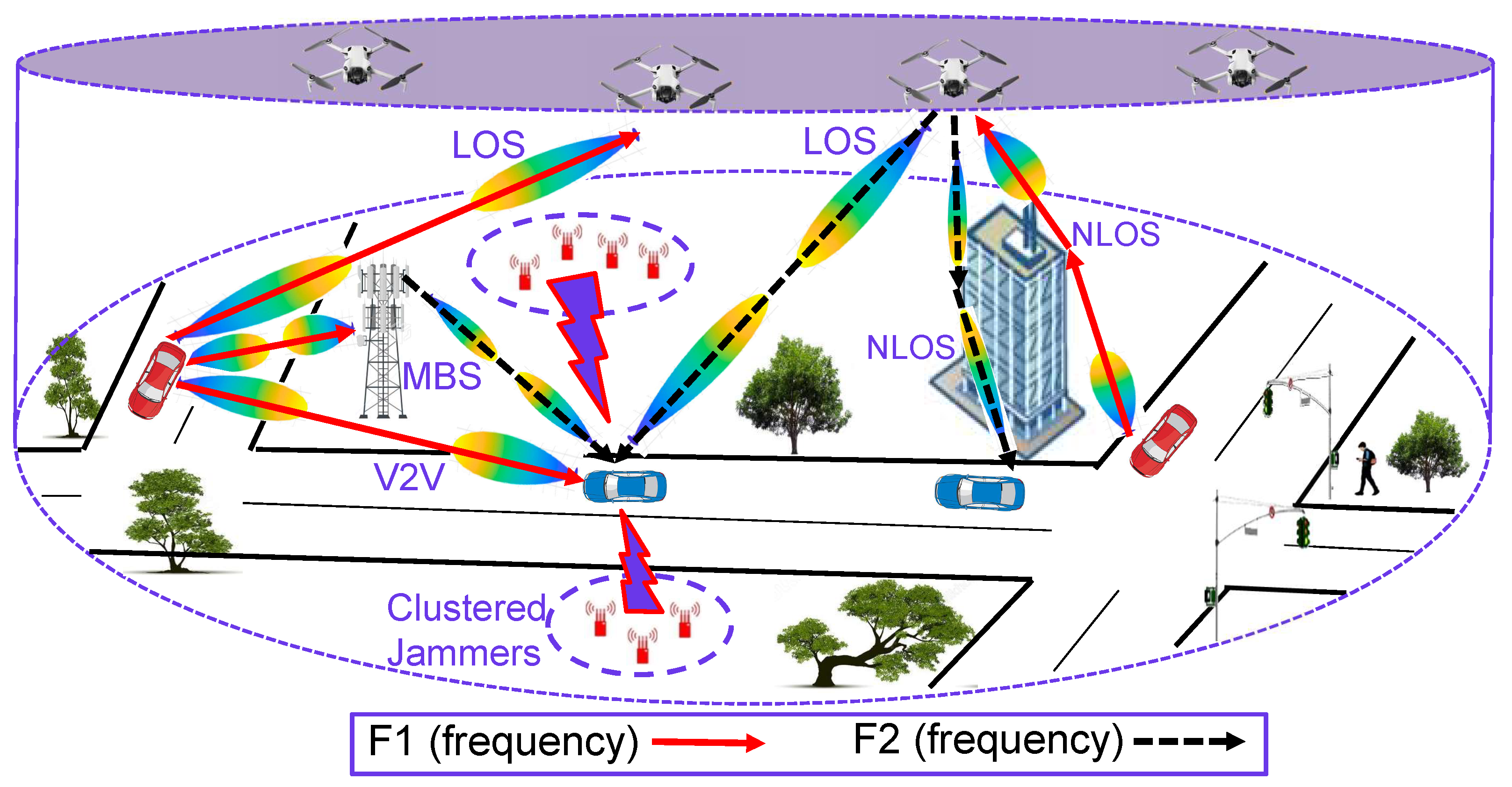
  • A framework for a UAV-assisted C-V2X network, which considers jammers and beam variations, is presented.
  • The performance of V2V, V2M, V2L, and V2N connections, considering clustered jamming, is evaluated in terms of coverage and SE by varying network parameters such as the number of V-Ns, MBSs, and LAPs.
  • Analytical equations for the association and coverage of V2V, V2M, V2L, and V2N connections, along with the clustered jamming devices, are derived.
  • The outcomes demonstrate that the effectiveness of UAV-assisted C-V2X transmissions is severely degraded in a network that is exploited by jamming and beam variations.
The rest of the article is described in the following: A UAV-assisted C-V2X system exploited by jammers is modeled in Section 2. The distance distributions for base stations, UAVs, and V-Ns are described in Section 3. The association of the equipment with the base station, LOS UAV, NLOS UAV, and V-N is derived in Section 4. Interference of the V-Ns, base stations, LOS UAVs, NLOS UAVs, and clustered jammers is evaluated in Section 5, whereas coverage and SE analysis are presented in Section 6. Mitigating techniques to overcome the effect of jamming interference are presented in Section 7, and the main outcomes of the paper, as well as the simulation setup and limitations, are discussed in Section 8. Finally, the conclusion of the paper is presented in Section 9.
A list of recent works addressing their system model, primary contributions, as well as outcomes and limitations, is given in Table 1.

2. System Model

In our system, the transmitting (typical) V-N, consisting of a vehicle, a pedestrian, or an RSU, connects a nearby V-N through a direct link or through a shared infrastructure that employs a LOS-LAP, an NLOS-LAP, or an MBS. The UAVs, MBSs, and V-Ns have been represented with stochastic geometry. The MBSs, represented by M, are generated according to a 2D PPP, Φ M , with a density function, λ M . Each MBS, indicated by the j-th MBS, is situated in a two-dimensional environment with dimensions ( x j , y j ) , wherein j = 1 , 2 , , m and m indicates the MBSs. The transmission power of the MBS is P M . The path loss exponent for the MBS connectivity is α M , whereas the extra path loss is η M . The MBS’s small-scale channel-dependent fading uses Rayleigh fading, which gives the fading gain as g M exp ( 1 ) (see Figure 1).
The Poisson line process (PLP), Φ V , is used to represent the V-Ns, V. The density of the roads is λ R , whereas the density of the V-Ns on each road is λ V , where λ V = λ p e d + λ r s u + λ v e h . Here, λ p e d reflects the pedestrian density, λ r s u reflects the density of RSUs, and λ v e h reflects the density of vehicles. The communicating V-Ns, Φ t , with density λ t , transmit with frequency p ; therefore, λ t = p λ V . The process considering receiver V-Ns is given as Φ r with density λ r = ( 1 p ) λ V . The transmission power of the V-N is P V . The path loss exponent for the V-N connectivity is α V , whereas the biasing factor is η , where η [ 0 , ) . A biasing value of 0 indicates that a V-N may be linked with the MBS, a UAV with LOS visibility, or a UAV with NLOS visibility; however, a biasing factor traversing infinity indicates that a V-N will connect with a neighboring V-N. The channel-dependent fading linked with the V-N reflects Rayleigh fading, with the fading gain g V exp ( 1 ) .
UAVs, U, are modeled using a 3D PPP, Φ U . The UAVs’ density is λ U , and their height is h U . The i-th LAP may be depicted in a 3D space using ( x i , y i , h U ) , wherein i { 1 , 2 , , u } and the number of UAVs is u. Furthermore, U { L , N } , where L indicates LOS-LAPs and N indicates NLOS-LAPs. The LAP’s power is P U . The path loss exponents for L and N are α L and α N , respectively. The extra path loss for L and N is η L and η N , respectively. The LAP’s channel-dependent fading adopts Nakagami-m fading with a stochastic distribution g U ( t ) = m U m U t m U 1 exp ( m U t ) Γ ( . ) throughout the equipment and the LAP channel, wherein m U { L , N } indicates fading and Γ ( . ) represents the Gamma distribution [29]. The LAP’s fading gain is t = x 2 , with t Γ ( m U , 1 / m U ) , wherein x is a Nakagami- m U . The LAP’s LOS probability is calculated as follows:
p L ( z L ) = 1 + A . e 180 π B · θ + A · B 1 ,
where A and B are determined by the environment. θ = arctan ( h U / D L ) , where D L represents the V-N and L distances. Taking the complement of p L ( z L ) yields p N , the NLOS-LAP probability.
This paper modeled the antenna pattern of the UAV by considering a uniform square array antenna of N × N elements. Beamforming assumes high-gain antennas with directional capabilities installed on UAVs to compensate for significant millimeter-wave frequency transmission losses, especially for long-distance and high-bandwidth backhaul communications. Beamforming antenna structures that are small, light, affordable, and appropriate for UAVs with constrained payload capacity are considered for the UAV-assisted C-V2X communications. The UAVs used an identical square antenna arrangement with N × N elements that evenly distribute themselves throughout the x-axis and y-axis directions to provide robust beamforming even when fluctuations are caused by mobility. Beamforming also assumed identical antenna arrays’ power; such an assumption makes it easier to analyze an ideal array dimension, which improves transmission rate without taking the system layout and UAV instabilities into consideration.
In real-world settings, accomplishing an ideal alignment of the beam is an extreme challenge because of the excessive ambient wind, atmospheric pressure, mechanical noise, and controlling-motor imperfections of the UAVs, which influence angle, θ , and phase, ϕ , of the 3D beam width. σ x and σ y represent the antenna’s x–z and y–z vibration orientations, respectively. The angle and phase affiliated with the oscillating 3D beam width are specified as follows: θ = tan 1 tan ( σ x ) 2 + tan ( σ y ) 2 and ϕ = arctan tan ( σ y ) tan ( σ x ) , respectively.
The number of transmitting and receiving antennas linked to the device (i.e., LOS-LAP, NLOS-LAP, MBS, or V-N) is provided by N t × N r . The transmitting and receiving antennas are represented by t and r, correspondingly, with t , r L , N , M , V . The square array antenna’s transmitting and receiving gains are calculated as G W = G W o × G W E × G W A , wherein W t , r . G W o is the highest antenna gain for the beam’s main lobe, G W E is the single antenna element gain in the θ and ϕ directions, and G W A is the antenna array gain using uniform radiation.
The antenna’s square array gain is defined as: [30]
G W A = sin N W Ξ x + x 2 N W sin Ξ x + x 2 sin N W Ξ y + y 2 N W sin Ξ y + y 2 2 ,
where Ξ x = ν x Ψ x δ x and Ξ y = ν y Ψ y Δ y such that Δ y = sin ( θ ) sin ( ϕ ) while δ x = sin ( θ ) cos ( ϕ ) . Furthermore, the wave number is defined as ν x = ν y = 2 π f c , where f c indicates the frequency. The plate thickness is specified by Ψ x = Ψ y = c / 2 f c , and the progressive phase shift is x = y = 0 ° .
The antenna element gain is defined as [31]
G W E = G E , max min { G ( θ E ) + G ( θ x ) , } ,
where G = min 12 θ E 90 ° V 2 , , G = min 12 θ E H 2 , and θ E = tan 1 1 + sin 2 ( θ x ) sin ( θ y ) 0.5 . G E , max is typically considered to be 8 dBi. The reflected x-axis and y-axis beam width is given by H = V = 65 ° . = 30 dB represents the limit of antenna side lobes, whereas = 30 dB represents the front-to-back antenna ratio.
To ensure equal radiated power from N antennas, the greatest gain coefficient with θ = 0 ° using Equation (2.22) of [30] is
G W o = 4 π 0 2 π 0 π G W A sin ( θ ) d θ d ϕ .
An exclusive path loss approach to millimeter waveband-based connectivity has not yet been defined for remote regions; therefore, 3GPP’s path loss model for remote regions is taken into consideration. We assume a millimeter waveband-dependent path loss framework for rural terrain (as presented in [23,32]) and configure the network configurations of rural environments provided by rural macros (RMas), rather than dense urban areas. To analyze the dense urban areas like urban macro (UMa) or urban micro (UMi), the path loss models presented in [31] for UMa or UMi can be considered. Since UMa and UMi pathloss models are conventionally considered when the base station height limitations are up to 25 m and 10 m, respectively, whereas RMa base station heights are up to 150 m, taking RMa into account allows us greater freedom in selecting the base station altitudes of the considered C-V2X network assisted by UAVs. The path loss is expressed for building altitudes, H b , up to 50 m and wireless tower altitudes up to 150 m and is given as follows [31]:
Z ( z ) = 20 log 10 40 π z f c 3 + min 0.03 H b 1.73 , 10 × log 10 ( z ) min 0.044 H b 1.73 , 14.77 + 0.002 z log 10 ( H b ) .
The jamming devices are distributed using an MCP such that the parent nodes or the cluster centers are distributed in a 2D space using PPP. The child nodes, or the jamming devices, are placed around the cluster center in a circle of radius, r J , using a uniform distribution. The jamming devices are distributed uniformly within a cluster of a circular radius. This is because, for the clustered jamming, the system modeling of jammers considers that the jammers are distributed according to an MCP. It is not limiting the research problem in the sense that the size of the radius of the cluster can be increased or decreased to account for the realistic nature of jammers, which are typically present in clusters in the real-world scenario. Moreover, the uniform distribution of jammers facilitates the fact that a typical jammer can be present anywhere in a cluster with a uniform probability. The jamming clusters, λ J , and jamming devices, J are both Poisson random variables. The jamming devices transmit the jamming signal with power, P J . The path loss associated with the jammers is expressed as α J .
In this work, we assumed that a typical transmitting V-N is allowed to associate and communicate with the recipient V-N either by utilizing infrastructure such as multiple UAVs (e.g., LOS-LAPs or NLOS-LAPs) and MBSs or without utilizing the infrastructure. LOS UAVs as well as NLOS UAVs both exploit 3D beam-width radiations. The work analyzes an interference-limited setting in which interference signals from the user’s devices (M, L, N, and V) have dominated the noise. The typical road with a receiving V-N is placed at the origin without affecting the point process distribution. Slivnyak’s Theorem [33] states that the process distribution is unchanged by placing a V-N on a road that traverses the origin. Figure 2 indicates the interfering signals from the equipment at the point of receiving V-N. The signal-to-interference ratio (SIR) is given as SIR t 2 r = P t g t G t G r z r z t α r I X , wherein I X represents the cumulative interference of devices deployed at the site, X. Pre-established coverage threshold is given as τ . In V 2 d connection, the SIR incorporating jamming may be stated as
SIR V 2 d = P V η g V G V , t G d , r z d z V α d I V o + I V + I J ,
wherein d = { L , N , M } , z V is the Euclidean distance from transmitting V-N to the node at origin, o, and z d is the Euclidean distance from d to the node at o, G V , t indicates transmitting V-N gain, G d , r indicates recipient device gain, I V o represents the V-Ns’ interfering signals from nodes on roads that pass the o, I V represents the interference of all V-Ns on roads other than those that pass o, and I J represents the interference of jammers placed in clusters. The SIR of d 2 V connection incorporating jamming may be stated as
SIR d 2 V = P d η d 1 g d G d , t G V , r z d α V I L + I N + I M + I J ,
where G d , t indicates transmitter device gain, G V , r indicates recipient V-N gain, and I L , I N , and I M are the interference of the L, N, and M, respectively, at the origin. Similarly, the SIR of the V2V connection incorporating jamming can be expressed as
SIR V 2 V = P V η g V G V , t G V , r z V α V I V o + I V + I J .

3. Distance Distribution

The traditional V-N connects to the closest device, d (i.e., M, L, N, or V), at a position, z, with a random variable, Z d . For an MBS connected to a V-N, Z M is the random variable describing distance, and it is assumed that all the interfering equipment is placed outside z. Considering the usual V-N linked to the closest MBS, the cumulative distribution function (cdf) of the Z M is represented by [34] as
F M ( z ) = 1 e π λ M z 2 .
The probability density function (pdf) for the MBS connection is represented as
f M ( z ) = d F M ( z ) / d z = 2 π λ M z e ( π λ M z 2 ) .
For the V-N associated with the LAP (i.e., Q { L , N } ), the cdf of the LAP’s distance is given as [35]
F Q ( z ) = 1 e 2 π λ U h U z t p Q t 2 h U 2 d t .
The pdf of the LAP’s distance is given as
f Q ( z ) = 2 π λ U t p Q t 2 h U 2 e 2 π λ U h U z t p Q t 2 h U 2 d t .
For the V-N attached to the closest V-N, the pdf of the V-N’s distance may be obtained through the cdf indicated in Appendix A and is represented as
f V ( z ) = d F V ( z ) d z = 2 exp 2 λ V z + 2 π λ R 0 z 1 e 2 λ V z 2 y 2 d y × λ V + 2 π λ R λ V 0 z z e 2 λ V z 2 y 2 z 2 y 2 d y .

4. Typical Vehicle’s Association

Based on the received power, the V-N connects to the equipment (for example, M , L , N , V ). The conventional V-N affiliation is the formation of a link between the V-N and the actual device.

4.1. Probability of V2V Association

The typical V-N connects to a neighboring V-N whenever the power acquired for the V2V link is greater than the power acquired for the V2M, V2L, or V2N linkages. The probability of V2V association is derived as
A V = Pr G T G R z V α V η 1 > G T G R z M α M η M × Pr G T G R z V α V η 1 > G T G R z L α L η L × Pr G T G R z V α V η 1 > G T G R z N α N η N = a Pr z M > z α V α M η 1 G M η M G V 1 α M Pr z L > z α V α L η 1 G L η L G V 1 α L Pr z N > z α V α N η 1 G N η N G V 1 α N = b Pr z M > z α V α M η 1 G M , O η M G V , O 1 α M Pr z L > z α V α L η 1 G L η L G V , O 1 α L Pr z N > z α V α N η 1 G N η N G V , O 1 α N = c 0 1 F M V ( z ) f V ( z ) d z × h U 1 F L V ( z ) f V ( z ) d z × h U 1 F N V ( z ) f V ( z ) d z ,
where (a) is simplified, (b) is the supposition that MBS and V-N accomplish the highest gain in contrast to LOS- and NLOS-LAP because of insignificant beam-width vibrations, and (c) is the representation of the likelihoods of the links in relation to the cdf and pdf of the distances between them. Equation (15) expresses the association probability of the V2V link by assuming that h U > 0 and that the initial limits of the z-axis are greater than zero.
A V = 0 exp π λ M z α V α M η 1 G M , O η M G V , O 1 α M 2 2 exp 2 λ V z + 2 π λ R 0 z 1 e 2 λ V z 2 y 2 d y × λ V + 2 π λ R λ V 0 z z e 2 λ V z 2 y 2 z 2 y 2 d y d z × h U exp π λ U h U z α V α L η 1 G L η L G V , O 1 α L p L z α V α L η 1 G L η L G V , O 1 α L 2 h U 2 d t 2 exp 2 λ V z + 2 π λ R 0 z 1 e 2 λ V z 2 y 2 d y × λ V + 2 π λ R λ V 0 z z e 2 λ V z 2 y 2 z 2 y 2 d y d z × h U exp π λ U h U z α V α N η 1 G N η N G V , O 1 α N p N z α V α N η 1 G N η N G V , O 1 α N 2 h U 2 d t 2 exp 2 λ V z + 2 π λ R 0 z 1 e 2 λ V z 2 y 2 d y × λ V + 2 π λ R λ V 0 z z e 2 λ V z 2 y 2 z 2 y 2 d y d z .

4.2. Probability of V2M Association

The V-N connects to the MBS whenever the mean signal strength gained from the V-N at the MBS (i.e.,) exceeds the mean signal strength of the V2V, V2L, or V2N connections. The expression is derived by following the derivation of (14) and is given in (17). The probability of V2M association is derived by assuming that h U > 0 and that the initial limits of the z-axis are greater than zero. Association probability of V2M connection is given as
A M = Pr G T G R z M α M η M > G T G R z L α L η L × Pr G T G R z M α M η M > G T G R z N α N η N × Pr G T G R z M α M η M > G T G R z V α V η 1 = Pr z L > z α M α L η M G L η L G M , O 1 α L Pr z N > z z α M α N η M G N η N G M , O 1 α N Pr z V > z α M α V η M G V η 1 G M , O 1 α V = h U 1 F L M ( z ) f M ( z ) d z × h U 1 F N M ( z ) f M ( z ) d z × 0 1 F V M ( z ) f M ( z ) d z .
A M = h U exp 2 π λ U h U z α M α L η M G L η L G M , O 1 α L p L z α M / α L η M G L η N G M , O 1 α L 2 h U 2 d t 2 π λ M z exp ( π λ M z 2 ) d z × h U exp 2 π λ U h U z α M α N η M G N η N G M , O 1 α N p N z α M α N η M G N η N G M , O 1 α N 2 h U 2 d t 2 π λ M z exp ( π λ M z 2 ) d z × 0 exp 2 π λ R 0 z α M / α V η M G V η 1 G M , O 1 / α V 1 e 2 λ V z α M / α V η M G V η 1 G M , O 1 / α V 2 y 2 d y exp ( 2 λ V z ) 2 π λ M z exp ( π λ M z 2 ) d z .

4.3. Probability of V2L Association

The traditional V-N links to the LOS-LAP if the V-N’s average signal quality at the nearest LOS-LAP exceeds the power acquired at the nearest MBS, NLOS-LAP, and V-N. The equation is produced through the same method as acquired in (14). The probability of V2L association is derived by assuming that h U > 0 and that the initial limits of the z-axis are greater than zero. The association probability of the V2L connection is given as
A L = Pr G T G R z L α L η L > G T G R z M α M η M × Pr G T G R z L α L η L > G T G R z N α N η N × Pr G T G R z L α L η L > G T G R z V α V η 1 = Pr z M > z α L α M η L G M , O η M G L 1 α M × Pr z N > z α L α N η L η N 1 / α N × Pr z V > z α L α V η L G V , O η 1 G L 1 α V = h U 1 F M L ( z ) f L ( z ) d z × h U 1 F N L ( z ) f L ( z ) d z × 0 1 F V L ( z ) f L ( z ) d z .
Equation (18) presents the association likelihood of the V2L connection and is expressed in (19).
A L = h U exp π λ M z α L α M η L G M , O η M G L 1 α M 2 2 π λ U t p L t 2 h U 2 exp 2 π λ U h U t p L t 2 h U 2 d t d z × h U exp 2 π λ U h U z α L α N η L η N 1 α N p N z α L α N η L η N 1 α N 2 h U 2 d t 2 π λ U t p L t 2 h U 2 exp 2 π λ U h U t p L t 2 h U 2 d t d z × 0 exp 2 π λ R 0 z α L / α V η L G V , O η 1 G L 1 / α V 1 e 2 λ V z α L / α V η L G V , O η 1 G L 1 / α V 2 y 2 d y 2 π λ U t p L t 2 h U 2 exp 2 π λ U h U t p L t 2 h U 2 d t d z .

4.4. Probability of V2N Association

The conventional V-N links to the NLOS-LAP whenever the power gained from the V-N located at the closest NLOS-LAP exceeds the power gained at the closest MBS, LOS-LAP, and V-N. Employing the same methods as in (14), an association of V-N with NLOS UAV is obtained. The probability of V2N association is derived by assuming that h U > 0 and that the initial limits of the z-axis are greater than zero. Association probability of V2N connection is given as
A N = Pr G T G R z N α N η N > G T G R z M α M η M × Pr G T G R z N α N η N > G T G R z L α L η L × Pr G T G R z N α N η N > G T G R z V α V η 1 = Pr z M > z α N α M η N G M , O η M G N 1 α M × Pr z L > z α N α L η N η L 1 / α N × Pr z V > z α N α V η N G V , O η 1 G N 1 α V = h U 1 F M N ( z ) f N ( z ) d z × h U 1 F L N ( z ) f N ( z ) d z × 0 1 F V N ( z ) f N ( z ) d z .
Equation (21) is the association probability of the V2N, which is obtained by substituting the values in (20).
A N = h U exp π λ M z α N α M η N G M , O η M G N 1 α M 2 2 π λ U t p N t 2 h U 2 exp 2 π λ U h U t p N t 2 h U 2 d t d z × h U exp 2 π λ U h U z α N α L η N / η L 1 α L p L z α N α L η N η L 1 α L 2 h U 2 d t 2 π λ U t p N t 2 h U 2 exp 2 π λ U h U t p N t 2 h U 2 d t d z × 0 exp 2 π λ R 0 z α N / α V η N G V , O η 1 G N 1 / α V 1 e 2 λ V z α N / α V η N G V , O η 1 G N 1 / α V 2 y 2 d y 2 π λ U t p N t 2 h U 2 exp 2 π λ U h U t p N t 2 h U 2 d t d z .

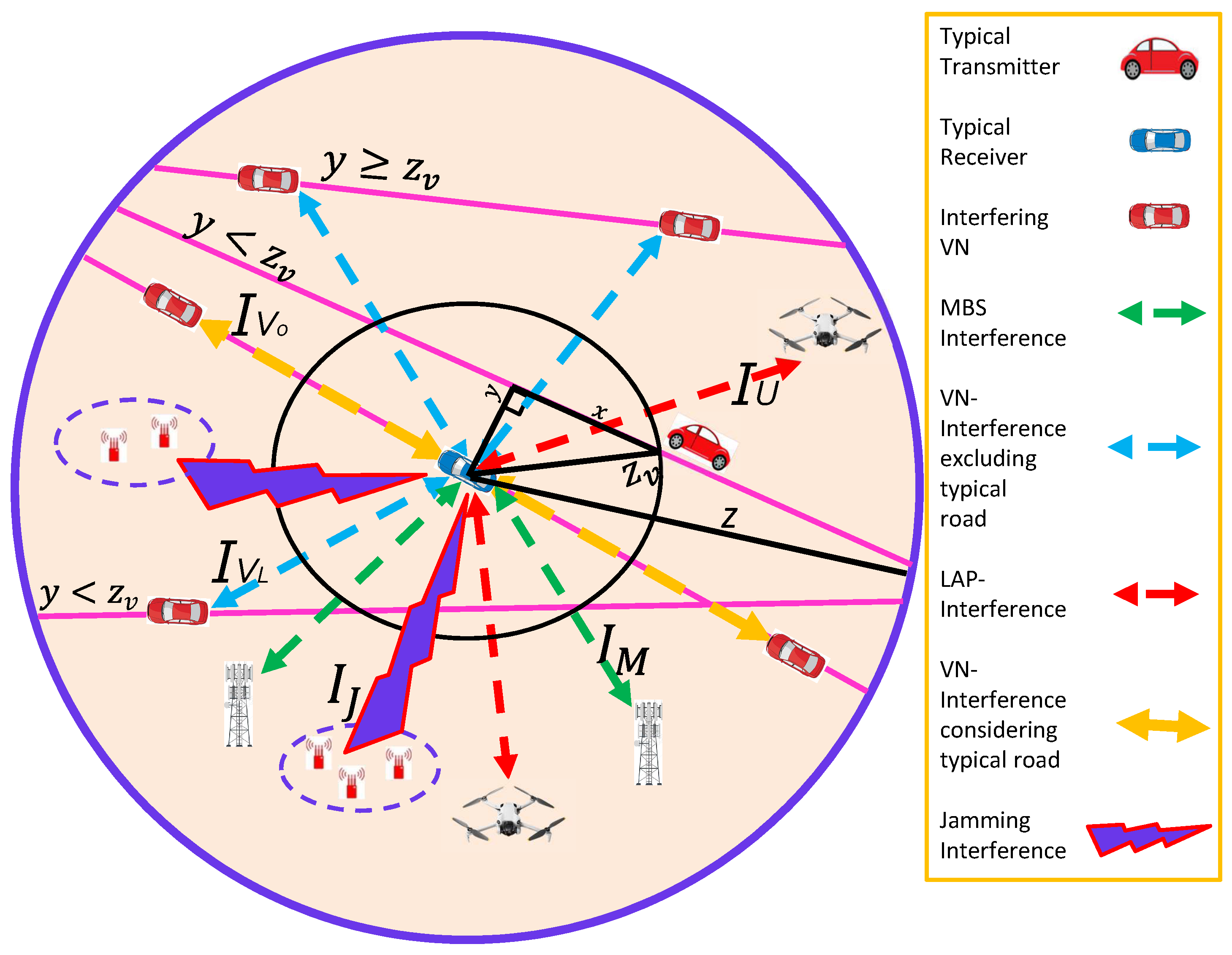
5. Interference Analysis

The signal received at the recipient V-N can be interrupted by the signals (or interference) of all the other nodes that are interacting via direct mode and shared mode transmission. The reception of a V-N’s transmission is impacted solely by the transmission of V-Ns, which are broadcasting to neighboring V-Ns via direct mode transmission. For shared mode transmission, the transmission of V2M, V2L, or V2N links is going to be disturbed by transmissions from all other V2M, V2L, or V2N links.
Interfering signals of MBSs, LOS-LAPs, NLOS-LAPs, and V-Ns are denoted as L I X ( s ) , wherein X may correspond to MBSs, LOS-LAPs, NLOS-LAPs, or V-Ns (i.e., X { M , L , N , V } ). The interference is provided as: L I X ( s ) = E [ e s I X ] , I X = i X P i g i η i 1 G t , i G r , i z r , i z t , i α i , wherein P i is the i-th node power. g i is the small-scale fading gain for the i-th node, while η i is the extra path loss for the i-th node. G t , i is the i-th sending node gain, G r , i is the i-th receiving node gain, z t , i is the distance between the transmitting node and o, z r , i is the Euclidean distance between the receiving node and o, and α i is the path loss of the i-th node. Thus, the Laplace expression can be expressed as L I X ( s ) = E g , X e s i X P i g i η i 1 G t , i G r , i z r , i z t , i α i , where the expectation is with respect to g and X. By taking the expectation with respect to g exp ( 1 ) , the expression can be written as
L I X ( s ) = E X i X 1 1 + s P i η i 1 G t , i G r , i z r , i z t , i α i .

5.1. V-Ns Interference

The interference between V-Ns at the recipient V-N may be represented as L I X ( s ) , wherein X is V and is derived by presuming Rayleigh fading for g V . V-N interference is divided into two distinct categories: (i) interference from V-Ns that are not situated on a conventional road traversing the origin, and (ii) interference from V-Ns that belong on a road that traverses the origin [11]. The interference of non-typical road V-Ns may be obtained by supposing that there are two distinct types of V-Ns, i.e., (a) the V-Ns that are positioned at a distance of y z V (e.g., L I V ( s ) ), where y is the perpendicular distance to z V such that z V is the radius of the sphere centered at the origin, S ( o , z V ) , and (b) the V-Ns that are located at a distance of y < z V (e.g., L I V ı ( s ) ). It is important to note that for the V-Ns with distance, y < z V , only the V-Ns located on a road (or a line segment) between z 2 y 2 , z V 2 y 2 and z V 2 y 2 , z 2 y 2 will create interference. Whereas, for the V-Ns with distance y z V , the V-Ns located on a road (or a line segment) between z 2 y 2 , z 2 y 2 will create interference.
The V-Ns’ interference is placed at a straight line segment (road) z 2 y 2 , z 2 y 2 . is obtained by ensuring that the V-Ns are placed on the road as a PPP, with the pdf provided by f ( t 1 ) = 1 2 z 2 y 2 . Given that the total quantity of V-Ns on the road is j, the interference is represented as
L I V ( s ) = j 0 P { V = j } z 2 y 2 z 2 y 2 f ( t 1 ) d t 1 1 + s P V B G t G r y 2 + t 1 2 α r 2 j .
Plugging f ( t 1 ) into (23) and the probability of nodes, P { V = j } , that follows PPP-distribution, the interference is expressed as
L I V ( s ) = j 0 e 2 λ V z 2 y 2 2 λ V z 2 y 2 j j ! 2 z 2 y 2 j z 2 y 2 z 2 y 2 d t 1 1 + s P V B G t G r y 2 + t 1 2 α r 2 j .
Using simple mathematics, the expression can be written as
L I V ( s ) = j 0 e 2 λ V z 2 y 2 j ! 2 λ V z 2 y 2 2 z 2 y 2 z 2 y 2 z 2 y 2 d t 1 1 + s P V B G t G r y 2 + t 1 2 α r 2 j .
Using t 2 t 2 = 2 0 t 2 and j = 0 Y j j ! = e Y , we get
L I V ( s ) = e 2 λ V z 2 y 2 exp 2 λ V 0 z 2 y 2 d t 1 1 + s P V B G t G r y 2 + t 1 2 α r 2 .
After simplification, the V-Ns’ interference located at a single road with y z V is given as
L I V ( s ) = exp 2 λ V 0 z 2 y 2 1 1 1 + s P V B G t G r y 2 + t 1 2 α r 2 d t 1 .
For α r > 1 , the closed-form expression is given as
L I V ( s ) = exp 2 λ π ( s P V B G t G r ) α r csc π α r α r .
Following a similar procedure of (26), the V-Ns interference for a single road with y < z V can be computed and is given as
L I V ı ( s ) = exp 2 λ V z V 2 y 2 z 2 y 2 1 1 1 + s P V B G t G r y 2 + t 1 2 α r 2 d t 1 .
The roads are distributed in the given region considering a PPP, and the average number of roads with y < z V is given as 2 λ R λ V ( z z V ) , and the average number of roads with y z V is given as 2 λ R λ V z . Let j 1 and j 2 be the number of roads such that j 1 has the pdf, f ( t 1 ) = 1 2 z with y z and j 2 has the pdf, f ( t 2 ) = 1 2 ( z z V ) with y < z . Thus, the V-Ns interference, considering all the roads other than the typical road that passes o, can be expressed as
L I V ( s ) = j 1 0 exp 2 λ R λ V z ( 2 λ R λ V z ) j 1 j 1 ! z z L I V ( s ) f ( t 1 ) d t 1 j 1 j 2 0 exp 2 λ R λ V ( z z V ) 2 λ R λ V ( z z V ) j 2 j 2 ! z V z L I V ı ( s ) f ( t 2 ) d t 2 j 2 .
Substituting f ( t 1 ) and f ( t 2 ) in (29) and simplifying the expression, we get
L I V ( s ) = e 2 λ R λ V z j 1 0 2 λ R λ V 0 z L I V ( s ) d t 1 j 1 j 1 ! e 2 λ R λ V ( z z V ) j 2 0 2 λ R λ V z V z L I V ı ( s ) d t 2 j 2 j 2 ! .
Employing i = 0 Y i / i ! = e Y , (30) is simplified as
L I V ( s ) = e 2 λ R λ V z e 2 λ R λ V 0 z L I V ( s ) d t 1 e 2 λ R λ V ( z z V ) e 2 λ R λ V z V z L I V ı ( s ) d t 2 .
The final expression of the V-Ns interference, excluding the typical road passing origin, is expressed as
L I V ( s ) = exp 2 λ R λ V 0 z 1 L I V ( s ) d t 1 + z V z 1 L I V ı ( s ) d t 2 .
The V-Ns interference from the typical road passing o is expressed by substituting y = 0 in (28). This is expressed as
L I V o ( s ) = exp 2 λ V z V z 1 1 1 + s P V B G V , t G V , r b α r d b .
Substituting z V 0 as well as z > 0 and α r > 1 in (33), the interference expression is expressed as
L I V o ( s ) = exp 2 λ V G V , t G V , r z F 1 2 1 , 1 + α r / α r ; 2 1 / α r ; G V , t G V , r z 1 + α r ,
where F 1 2 ( , ; ; ) is the hyper-geometric function [36].

5.2. MBSs Interference

The L I X ( s ) expression represents the MBSs’ interference at the point of recipient V-N, wherein X is M and is specified as
L I M ( s ) = E X M i X M 1 1 + s P i η i 1 G t , i G r , i z r , i z t , i α r .
Using coordinates in polar form and presuming the probability generating function (pgf) as E X f ( x ) = exp 2 π λ z 1 f ( x ) x d x [34]. The remaining statement for the MBS interference is as follows:
L I M ( s ) = exp 2 π λ M z M 1 1 1 + s P M η M 1 G t G r z r z t α r x d x .

5.3. LOS-LAPs Interference

The LOS-LAPs interference at the recipient V-N can be expressed as L I X ( s ) , wherein X is L, which is produced by presuming that g L implies Nakagami-m fading and is given as [16]
L I X ( s ) = E X L i X L 1 + s P L η L 1 G t , i G r , i z r , i z t , i α r m L m L .
Using coordinates that are polar and presuming the pgf of the point process, the equation is derived as
L I L ( s ) = exp 2 π λ L h U t p L t 2 h U 2 1 1 + s P L η L 1 G L , t G d , r z d z t α d m L m L d t .

5.4. NLOS-LAPs Interference

The NLOS-LAPs interference at the recipient V-N is computed as L I X ( s ) , wherein X is N and is derived by considering a similar procedure of (38) and is given as
L I N ( s ) = exp 2 π λ N h U t p N t 2 h U 2 1 1 + s P N η N 1 G N , t G N , r z d z N , t α d m N m N d t .

5.5. Jammers Interference

The MCP-distributed jamming clusters, λ J , with Poisson-distributed jammers, J, in a circular radius, r J , can degrade the efficiency of a UAV-assisted C-V2X network. The interference of the jamming clusters at the recipient node is derived in Appendix B and is given as
L I J = exp 2 π λ J J α J r J 2 τ 2 / α J csc 2 π α J z d 2 π λ J τ 2 / α J z d 2 0 z d 1 exp J 1 + ω α J / 2 d ω .

6. Performance Metrics

The following performance metrics help in validating the proposed method.

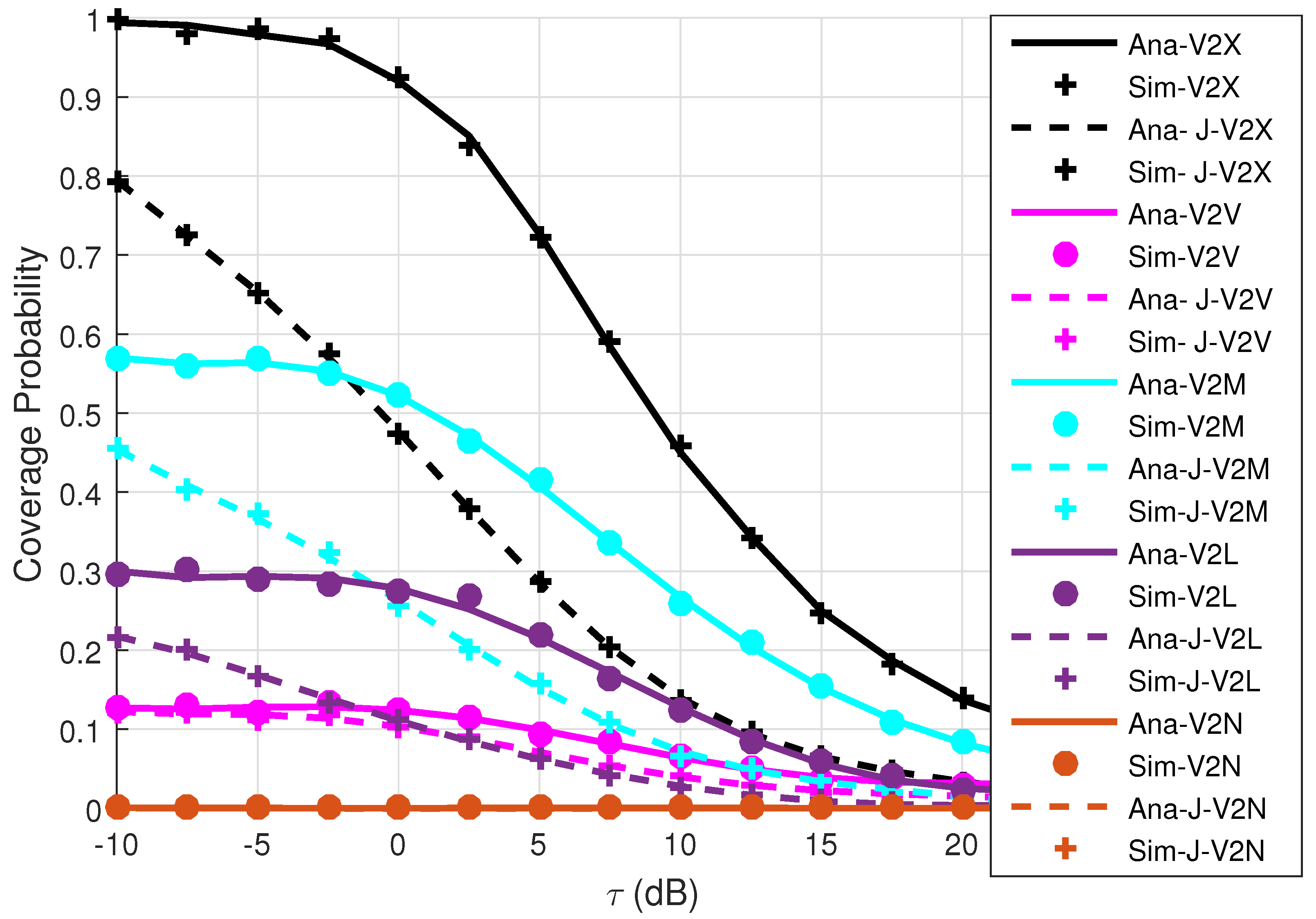
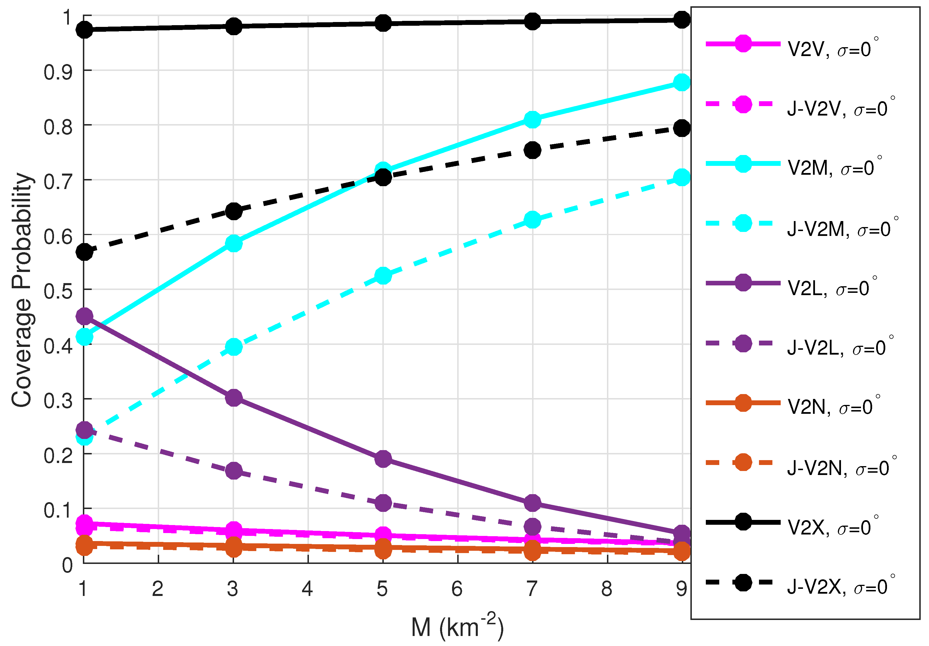
6.1. Coverage Probability

The V-N is considered to be within coverage whenever the SIR achieved at the recipient device surpasses the predefined limit. This is characterized as:
C = 0 Pr { SIR t 2 r τ } f r ( z ) d z = a 0 Pr P t η g t G t G r z r z t α r I X τ f r ( z ) d z = b 0 Pr g t τ ( I X ) P t η G t G r z r z t α r f r ( z ) d z = c 0 exp s ( I X ) f r ( z ) d z ,
where (a) yields by inserting SIR t 2 r , (b) yields by straightforward mathematical concepts, and (c) yields by g t exp ( 1 ) and s = τ P t η G t G r z r z t α r 1 . For direct mode transmission, the V2V link is considered to be within coverage whenever the SIR acquired at the recipient V-N surpasses the set limit. This can be obtained as
C V = 0 Pr { SIR V 2 V τ } f V ( z ) d z = a 0 Pr g V τ ( I V o + I V ) P V η G V , t G V , r z V α V f V ( z ) d z = b 0 exp s ( I V o + I V ) f V ( z ) d z = c 0 L I V ( s ) × L I V o ( s ) f V ( z ) d z ,
where (a) is obtained by simplification and inserting SIR V 2 V , (b) is derived by presuming g V exp ( 1 ) , and (c) is implied by the description of the Laplace transform. V2V connection’s coverage is calculated by entering the values of L I V ( s ) , L I V o ( s ) , and f V ( z ) in (42). The direct-mode coverage incorporating jamming can be evaluated as
C V , J = 0 L I V ( s ) × L I V o ( s ) × L I J f V ( z ) d z .
Substituting the values of L I V ( s ) , L I V o ( s ) , L I J , and f V ( z ) in (43), the expression is obtained and expressed in (44).
C V , J = 0 exp 2 λ R λ V 0 z 1 L I V ( s ) d t 1 + z V z 1 L I V ı ( s ) d t 2 exp 2 λ V z V z 1 1 1 + s P V η G V , t G V , r b α V d b exp 2 π λ J J α J r J 2 τ 2 / α J csc 2 π α J z d 2 π λ J τ 2 / α J z d 2 0 z d 1 exp J 1 + ω α J / 2 d ω 2 exp 2 λ V z + 2 π λ L 0 z 1 e 2 λ V z 2 y 2 d y λ V + 2 π λ L λ V 0 z z e 2 λ V z 2 y 2 z 2 y 2 d y d z .
For shared mode communication employing an MBS, the link is considered to be within coverage if the SIR achieved for both the V2M and M2V connections is greater than the specified limits and is expressed as
C M = 0 Pr { SIR V 2 M τ } f M ( z ) d z × 0 Pr { SIR M 2 V τ } f V ( z ) d z = a 0 L I V ( s ) × L I V o ( s ) f M ( z ) × 0 L I M ( s ) × L I L ( s ) × L I N ( s ) f V ( z ) d z ,
wherein (a) is derived by applying an analogous method to (42). It is crucial to note that in V2V transmissions, V-N signals interact with other V-N signals communicating at the same frequency, F 1 . In contrast, for traditional M2V, L2V, and N2V transmissions functioning at a frequency, F 2 , the corresponding conventional signals interfere with the other nodes sending via M2V, L2V, and N2V connections. By substituting the values of L I V ( s ) , L I V o ( s ) , f M ( z ) , L I M ( s ) , L I L ( s ) , L I N ( s ) , and f V ( z ) in (45), MBS coverage is obtained. The coverage of the MBS with jammers can be evaluated as
C M , J = 0 L I V ( s ) × L I V o ( s ) × L I J f M ( z ) × 0 L I M ( s ) × L I L ( s ) × L I N ( s ) × L I J f V ( z ) d z .
Substituting L I V ( s ) , L I V o ( s ) , f M ( z ) , L I M ( s ) , L I L ( s ) , L I N ( s ) , L I J , and f V ( z ) in (46), MBS coverage with jammers is obtained and is given in (47).
C M , J = 0 exp 2 λ R λ V 0 z 1 L I V ( s ) d t 1 + z M z 1 L I V ı ( s ) d t 2 exp 2 λ V z M z 1 1 1 + s P V η G V , t G M , r b α M d b exp 2 π λ J J α J r J 2 τ 2 / α J csc 2 π α J z M 2 π λ J τ 2 / α J z M 2 0 z M 1 exp J 1 + ω α J / 2 d ω . 2 π λ M z exp ( π λ M z 2 ) d z × 0 exp 2 π λ M z M 1 1 1 + s P M η M 1 G M , t G V , r z V z M α V x d x exp 2 π λ L h U t p L t 2 h U 2 1 1 + s P L η L 1 G L , t G V , r z V z L α V m L m L d t exp 2 π λ N h U t p N t 2 h U 2 1 1 + s P N η N 1 G N , t G V , r z V z N α V m N m N d t exp 2 π λ J J α J r J 2 τ 2 / α J csc 2 π α J z V 2 π λ J τ 2 / α J z V 2 0 z V 1 exp J 1 + ω α J / 2 d ω 2 exp 2 λ V z + 2 π λ L 0 z 1 e 2 λ V z 2 y 2 d y λ V + 2 π λ L λ V 0 z z e 2 λ V z 2 y 2 z 2 y 2 d y d z .
For shared mode communication utilizing the LOS-LAP, the link is considered to be within coverage whenever the SIR achieved for both the V2L and L2V connections is greater than the prescribed limits. This can be obtained as
C L = 0 Pr { SIR V 2 L τ } f L ( z ) d z × 0 Pr { SIR L 2 V τ } f V ( z ) d z = a 0 L I V ( s ) × L I V o ( s ) f L ( z ) × 0 L I M ( s ) × L I L ( s ) × L I N ( s ) f V ( z ) d z ,
where (a) is obtained by following a similar procedure to (45). Substituting the values of L I V ( s ) , L I V o ( s ) , f L ( z ) , L I M ( s ) , L I L ( s ) , L I N ( s ) , and f V ( z ) in (48), the LOS-LAP’s coverage is derived. The LOS-LAP’s coverage, including jamming, can be evaluated as
C L , J = 0 L I V ( s ) × L I V o ( s ) × L I J f L ( z ) × 0 L I M ( s ) × L I L ( s ) × L I N ( s ) × L I J f V ( z ) d z ,
Substituting L I V ( s ) , L I V o ( s ) , f L ( z ) , L I M ( s ) , L I L ( s ) , L I N ( s ) , L I J , and f V ( z ) in (49), the LOS-LAP’s coverage including jammers is derived and expressed in (50).
C L , J = 0 exp 2 λ R λ V 0 z 1 L I V ( s ) d t 1 + z L z 1 L I V ı ( s ) d t 2 exp 2 λ V z L z 1 1 1 + s P V η G V , t G L , r b α L d b exp 2 π λ J J α J r J 2 τ 2 / α J csc 2 π α J z L 2 π λ J τ 2 / α J z L 2 0 z L 1 exp J 1 + ω α J / 2 d ω . 2 π λ U t p L t 2 h U 2 e 2 π λ U h U z t p L t 2 h U 2 d t d z × 0 exp 2 π λ M z M 1 1 1 + s P M η M 1 G M , t G V , r z V z M α V x d x exp 2 π λ L h U t p L t 2 h U 2 1 1 + s P L η L 1 G L , t G V , r z V z L α V m L m L d t exp 2 π λ N h U t p N t 2 h U 2 1 1 + s P N η N 1 G N , t G V , r z V z N α V m N m N d t exp 2 π λ J J α J r J 2 τ 2 / α J csc 2 π α J z V 2 π λ J τ 2 / α J z V 2 0 z V 1 exp J 1 + ω α J / 2 d ω 2 exp 2 λ V z + 2 π λ L 0 z 1 e 2 λ V z 2 y 2 d y λ V + 2 π λ L λ V 0 z z e 2 λ V z 2 y 2 z 2 y 2 d y d z .
For the shared mode transmission using the NLOS-LAP, the connection of the NLOS-LAP is said to be in coverage if the SIR obtained for the V2N connection, as well as the N2V connection, is larger than the predefined values. This is given as
C N = 0 Pr { SIR V 2 N τ } f N ( z ) d z × 0 Pr { SIR N 2 V τ } f V ( z ) d z = a 0 L I V ( s ) × L I V o ( s ) f N ( z ) × 0 L I M ( s ) × L I L ( s ) × L I N ( s ) f V ( z ) d z ,
where (a) is obtained by following a similar procedure to (45). Substituting the values of L I V ( s ) , L I V o ( s ) , f N ( z ) , L I M ( s ) , L I L ( s ) , L I N ( s ) , and f V ( z ) in (51), the NLOS-LAP’s coverage is derived. The NLOS-LAP’s coverage with jammers can be derived as
C N , J = 0 L I V ( s ) × L I V o ( s ) × L I J f N ( z ) × 0 L I M ( s ) × L I L ( s ) × L I N ( s ) × L I J f V ( z ) d z ,
Substituting L I V ( s ) , L I V o ( s ) , f N ( z ) , L I M ( s ) , L I L ( s ) , L I N ( s ) , L I J , and f V ( z ) in (52), the NLOS-LAP’s coverage with jammers is derived and expressed in (53).
C N , J = 0 exp 2 λ R λ V 0 z 1 L I V ( s ) d t 1 + z N z 1 L I V ı ( s ) d t 2 exp 2 λ V z N z 1 1 1 + s P V η G V , t G N , r b α N d b exp 2 π λ J J α J r J 2 τ 2 / α J csc 2 π α J z N 2 π λ J τ 2 / α J z N 2 0 z N 1 exp J 1 + ω α J / 2 d ω . 2 π λ U t p N t 2 h U 2 e 2 π λ U h U z t p N t 2 h U 2 d t d z × 0 exp 2 π λ M z M 1 1 1 + s P M η M 1 G M , t G V , r z V z M α V x d x exp 2 π λ L h U t p L t 2 h U 2 1 1 + s P L η L 1 G L , t G V , r z V z L α V m L m L d t exp 2 π λ N h U t p N t 2 h U 2 1 1 + s P N η N 1 G N , t G V , r z V z N α V m N m N d t exp 2 π λ J J α J r J 2 τ 2 / α J csc 2 π α J z V 2 π λ J τ 2 / α J z V 2 0 z V 1 exp J 1 + ω α J / 2 d ω 2 exp 2 λ V z + 2 π λ L 0 z 1 e 2 λ V z 2 y 2 d y λ V + 2 π λ L λ V 0 z z e 2 λ V z 2 y 2 z 2 y 2 d y d z .
The V2X link’s coverage is expressed as
C = A V C V + A M C M + A L C L + A N C N .
Substituting the values of A V , A L , A N , A M , C V , C L , C N , and C M into (54), the coverage probability of the V2X connection is obtained. The coverage probability of the V2X connection with jammers can be derived as The V2X link’s coverage is expressed as
C J = A V C V , J + A M C M , J + A L C L , J + A N C N , J .
Substituting A V , A L , A N , A M , C V , J , C L , J , C N , J , and C M , J into (55), the coverage probability of the V2X connection with jammers is obtained.

6.2. Spectrum Efficiency

The SE is calculated as the ratio of Shannon’s capacity to the overall bandwidth, B . The capacity may be expressed as C = 0 0 B ln 1 + SIR t 2 r f r ( z ) d z d t . The SE of the V2V link without exploiting the jammers is calculated whenever the SIR of the V2V link without considering the jammers surpasses the specified limit. The SE is derived in App. C and is expressed as
S E V = 0 0 L I V ( s ¯ ) × L I V o ( s ¯ ) f V ( z ) d z d t .
The SE of the V2V connection with jammers can be evaluated by following the same procedure as App. C and is given as
S E V , J = 0 0 L I V ( s ¯ ) × L I V o ( s ¯ ) × L I J f V ( z ) d z d t .
Plugging L I V ( s ¯ ) , L I V o ( s ¯ ) , L I J , and f V ( z ) into (57), the SE of the V2V connection with jammers is determined.
The SE of the MBS link without jammers can be determined whenever the SIR of the V2M link and the M2V link is bigger than the specified limit. It is represented as
S E M = 1 2 0 0 ln 1 + SIR V 2 M f M ( z ) d z d t + 0 0 ln 1 + SIR M 2 V f V ( z ) d z d t = a 1 2 0 0 L I V ( s ¯ ) × L I V o ( s ¯ ) f M ( z ) d z d t + 0 0 L I M ( s ¯ ) × L I L ( s ¯ ) × L I N ( s ¯ ) f V ( z ) d z d t ,
where (a) is obtained by following a similar procedure to that which was derived in App. C. Plugging the values of L I V ( s ¯ ) , L I V o ( s ¯ ) , f M ( z ) , L I M ( s ¯ ) , L I L ( s ¯ ) , L I N ( s ¯ ) , and f V ( z ) in (58), the SE of the MBS without jammers is derived. The SE of the V2M connection with jammers is evaluated as
S E M , J = 1 2 0 0 L I V ( s ¯ ) × L I V o ( s ¯ ) × L I J f M ( z ) d z d t + 0 0 L I M ( s ¯ ) × L I L ( s ¯ ) × L I N ( s ¯ ) × L I J f V ( z ) d z d t .
Plugging L I V ( s ¯ ) , L I V o ( s ¯ ) , f M ( z ) , L I M ( s ¯ ) , L I L ( s ¯ ) , L I N ( s ¯ ) , L I J and f V ( z ) in (59), the SE of the MBS connection with jammers is derived.
The LOS-LAP’s SE is determined if the acquired SIR of both the V2L and L2V links is greater than the limit and is provided as
S E L = 1 2 0 0 ln 1 + SIR V 2 L f L ( z ) d z d t + 0 0 ln 1 + SIR L 2 V f V ( z ) d z d t = a 1 2 0 0 L I V ( s ¯ ) × L I V o ( s ¯ ) f L ( z ) d z d t + 0 0 L I M ( s ¯ ) × L I L ( s ¯ ) × L I N ( s ¯ ) f V ( z ) d z d t ,
where (a) is obtained by following a similar procedure to that which was derived in App. C. Plugging the values of L I V ( s ¯ ) , L I V o ( s ¯ ) , f L ( z ) , L I M ( s ¯ ) , L I L ( s ¯ ) , L I N ( s ¯ ) and f V ( z ) in (60), LOS-LAP’s SE without jammers is obtained. The SE of the LOS-LAP with jamming devices is evaluated as
S E L , J = 1 2 0 0 L I V ( s ¯ ) × L I V o ( s ¯ ) × L I J f L ( z ) d z d t + 0 0 L I M ( s ¯ ) × L I L ( s ¯ ) × L I N ( s ¯ ) × L I J f V ( z ) d z d t .
Plugging L I V ( s ¯ ) , L I V o ( s ¯ ) , f L ( z ) , L I M ( s ¯ ) , L I L ( s ¯ ) , L I N ( s ¯ ) , L I J , and f V ( z ) in (61), LOS-LAP’s SE with jammers is obtained.
The NLOS-LAP’s SE is calculated whenever the SIR of the V2N as well as the N2V link exceeds the limit and is computed as
S E N = 1 2 0 0 ln 1 + SIR V 2 N f N ( z ) d z d t + 0 0 ln 1 + SIR N 2 V f V ( z ) d z d t = a 1 2 0 0 L I V ( s ¯ ) × L I V o ( s ¯ ) f N ( z ) d z d t + 0 0 L I M ( s ¯ ) × L I L ( s ¯ ) × L I N ( s ¯ ) f V ( z ) d z d t ,
where (a) is obtained by following a similar procedure to that which was derived in App. C. The final expression for the SE of the NLOS-LAP connection without jammers is obtained by substituting the values of L I V ( s ¯ ) , L I V o ( s ¯ ) , f N ( z ) , L I M ( s ¯ ) , L I L ( s ¯ ) , L I N ( s ¯ ) and f V ( z ) in (62). The SE of the V2N connection with jamming devices is evaluated as
S E N , J = 1 2 0 0 L I V ( s ¯ ) × L I V o ( s ¯ ) × L I J f N ( z ) d z d t + 0 0 L I M ( s ¯ ) × L I L ( s ¯ ) × L I N ( s ¯ ) × L I J f V ( z ) d z d t .
Substituting L I V ( s ¯ ) , L I V o ( s ¯ ) , f N ( z ) , L I M ( s ¯ ) , L I L ( s ¯ ) , L I N ( s ¯ ) , L N , J , and f V ( z ) in (63), the SE of the V2N connection with jammers is obtained.
The SE of the overall link, i.e., the V2X connection, is given as
S E = A V S E V + A M S E M + A L S E L + A N S E N .
Plugging A V , S E V , A M , S E M , A L , S E L , A N , and S E N in (64), the SE of the V2X link is derived. The SE of the overall link with jammers, i.e., V2X connection with jammers, is given as
S E J = A V S E V , J + A M S E M , J + A L S E L , J + A N S E N , J .
Plugging A V , S E V , J , A M , S E M , J , A L , S E L , J , A N and S E N , J in (65), the SE of the V2X link with jammers is derived.

7. Mitigating Jamming Interference

To ensure the safe operation of vehicle networks while dealing with jamming transmitters, a number of strategies can be used to mitigate the negative effects of jamming equipment. Slot-based V2X systems are a potential side-link blocking approach [37] that can be used to lessen several negative effects of organized jamming. The use of deliberate side-link blocking and initiatives to jam V2X exchanges can be reduced by altering the rate at which information is exchanged. A probabilistic-channel browsing technique [38] that aims to react to the blocking disruption may also be employed to lessen the disruption brought on by the clustering process of jammers. The channel surfing technique mostly works by changing the control channel to a distinct channel. Also, an abrupt variation in channels can aid in minimizing the impact of jamming by broadcasting the messages and transmitting the contents on an un-jammed channel, as described in [39]. This strategy helps in reducing the negative effects of jamming. The work in [40] examines a convoy system that uses a behavior-based structure whereby VNs cooperate and exchange addresses to counter jammer assaults in an effort to lessen the interference triggered by jamming devices. Furthermore, in a jamming-disturbed environment, the multiple-input multiple-output-based method suggested in [41] may be applied to analyze the data obtained. In real-world scenarios, the rate-adaptation and power-management techniques outlined in [42,43] can possibly be applied to mitigate the disruptive effects of jamming devices.

8. Network Setup, Results, and Discussion

8.1. Simulation Setup and Limitations

Table 2 shows the simulation parameters for the considered system model. The choice of network parameters facilitates the fact that most of the outcomes of the analysis are quantified in terms of coverage and SE. The network parameters are set by following the specific method given in [11,16]. The simulation results are obtained on MATLAB (https://www.mathworks.com/products/matlab.html, accessed on 16 May 2025) software using 100,000 Monte Carlo runs by considering hardware, i.e., Intel (R) Core (TM) i7-12700 (20 CPUs), 2.1 GHz, with 16 GB RAM. Our analytical work is validated by simulations. The analytical results and simulation results are shown with legends A n a and S i m , respectively. The V2V connection is represented by pink color, the V2M connection is represented by cyan color, the V2L connection is represented by purple color, and the V2N connection is represented by brown color. The V2X connection is represented by the black color, showing the combined results of direct mode transmission and shared mode transmission. The standard deviation of the fluctuations of the beam width is represented by the filled circle with zero-degree variation, the filled hat with three-degree variation, and the filled hexagon with six-degree variation. The solid line and dashed-dotted line represent the network’s performance without including jamming and with including jamming, respectively.
Monte Carlo simulations are obtained to validate the analysis. For each of the Monte Carlo independent trials, the MBSs are allocated in the given 2D space based on a 2D PPP with an average value of MBSs given as λ M , while the V-Ns are allocated on each of the roads based on a PLP. The average number of roads is given as λ R , and the average number of V-Ns on each road, based on a 3D PPP, with an average value of LAPs given as λ U . The jammers are distributed using an MCP such that the number of clusters in the given region is a 2D PPP with an average number of clusters given in the region as λ J . For each of the clusters, the number of jammers is a Poisson random variable with a mean number of jammers in each cluster given as J. The jammers are distributed around each cluster center with a circular radius given as r J . For UAV-assisted C-V2X communications, the performance of the V-N is computed in terms of coverage and SE by assuming that for each of the Monte Carlo trials, a transmitting typical V-N wants to communicate with the recipient V-N located at the origin either by utilizing infrastructure such as multiple UAVs (e.g., LOS-LAPs or NLOS-LAPs) and MBSs or without utilizing the infrastructure (such as in V-N to V-N communications).
In V2X communications, the transmitting V-N (also known as the conventional typical V-N) wishes to connect with the nearby V-N (also known as the one that receives data). The receiving V-N is located at the origin, o. The most adjacent V-N to the recipient V-N is known as the typical node or the traditional node. Following choosing the typical V-N, it determines when to opt for the transmission in direct mode or the transmission in the shared mode according to the average power of the V-N from its origin or the average power of the V-N at the nearest MBS, at the nearest LOS-LAP, or at the nearest NLOS-LAP. The possibility of a conventional V-N to maintain a LOS interaction is determined using Equation (1), and its complementary function may be utilized for the NLOS connection.
The conventional V-N connects to the MBS during shared mode if the mean signal strength of the corresponding V-N at the MBS exceeds the mean signal strength of the V-N at the LOS-LAP, NLOS-LAP, and the recipient V-N. In shared mode communication, a standard V-N connects to the LOS-LAP if the mean strength of the signal of the V-N located at the LOS-LAP exceeds the mean signal strength of the characteristic V-N at the MBS, NLOS-LAP, and the recipient V-N. The traditional V-N connects to the NLOS-LAP in shared mode whenever the mean signal quality of the characteristic V-N located at the NLOS-LAP is greater compared with the mean power of the characteristic V-N at the LOS-LAP, MBS, and recipient V-N. The conventional V-N connects with the V-N in direct mode whenever the conventional V-N’s average signal quality at the place of origin surpasses the characteristic V-N’s average power at an MBS, LOS-LAP, or NLOS-LAP.
Efficiency in terms of coverage is determined following connecting to the node (e.g., V2V, V2L, V2N, or V2V connections). When the sender (e.g., V-N) establishes an association with the recipient V-N using direct mode delivery, the coverage is calculated by taking into account the interference generated by all V-Ns at the recipient as well as the jamming interference. For shared mode transfer, in which a user association has been created with the devices (e.g., V-N, MBS, LOS-LAP, NLOS-LAP), the SIR of the given link (e.g., at an MBS in V2V, at an LOS-LAP in V2L, at a NLOS-LAP in V2N, or a receiving V-N in V2V) is determined through assessing the cumulative interference of devices as well as the interference of clustered jammers. Whenever the SIR at the device (MBS/LOS-LAP/NLOS-LAP) as well as the SIR at the destination V-N exceed the specified value, the equipment’s interaction with MBS, LOS-LAP, or NLOS-LAP is deemed to be in range. Whenever the V2M/V2L/V2N or V2V link has sufficient coverage, the SE is determined for the considered device (for example, MBS, LOS-LAP, NLOS-LAP, or V-N) using Shannon’s capacity theorem. The efficiency of the V2X link’s coverage and bandwidth without jammers is calculated by combining the corresponding coverage and bandwidth of the V2M/V2L/V2N, or V2V links, without jammers. Whereas, the efficiency of the V2X link’s coverage and bandwidth with jammers is calculated by combining the corresponding coverage and bandwidth of the V2M/V2L/V2N, or V2V links, including jammers.
The main limitation of our proposed method is based on the fact that our system model is developed for a half-duplex network, and therefore, the bandwidth efficiency is lower than a full-duplex vehicular network, where the bandwidth approaches twice the bandwidth of a half-duplex vehicular network. Another limitation of our model is maintaining backhaul connectivity and synchronization in the presence of LOS and NLOS UAVs without affecting the bandwidth efficiency. Moreover, since UAVs are vulnerable to security attacks, it is difficult to maintain a stable and secure platform for UAV-assisted C-V2X communications. Also, one of the main challenges is to lower the control and signaling overheads during base station handovers.

8.2. Results and Discussion

Figure 3 shows the influence of the SIR threshold on the equipment’s coverage performance. The coverage probability of the V2X connection without jammers (black solid line) exceeds the coverage probability of the V2X connection with jammers (black dotted-dashed line). Similarly, the coverage probability of the V2V connection (pink solid line), V2M connection (cyan solid line), V2L connection (purple solid line), and V2V connection (brown solid line) without considering jammers exceeds the respective coverage probability of the V2V connection (pink dotted-dashed line), V2M connection (cyan dotted-dashed line), V2L connection (purple dotted-dashed line), and V2V connection (brown dotted-dashed line) with jammers. This is because by including jammers in the network, the cumulative interference for the corresponding links increases, which reduces the SIR and the coverage probability of the given links with jammers. Specifically, the coverage performance of the network decreases in percentage change up to 25.5% at a −10 dB SIR threshold in the presence of clustered jammers. Our proposed method to model and investigate a UAV-assisted C-V2X network validates the simulation results of coverage probability, showing that the coverage performance of the V-N links with jamming is efficiently characterized by employing MCP-distributed jammers.
Figure 4 shows the V-N’s influence on the equipment’s association probability. The association probability of the V2V connection improves with the increasing V-Ns, whereas the association probability of the V2M/V2L/V2N connection decreases with the increasing V-Ns because the path loss for the V2V connections decreases with increasing V-Ns in the network, which increases the SIR and association probability of the V2V connection. The association probability of the V2L and V2N connections decreases as compared with V2V and V2M connections when the fluctuation of a beam of the antenna increases (e.g., from σ = 0 ° to σ = 6 ° ) due to factors like wind pressure, atmospheric pressure, etc. The fluctuations in the beam width of the antenna result in lowering the antenna gain, the received power, and the association probability of the V2L and V2N connections.
Figure 5 illustrates the V-N’s impact on the equipment’s coverage probability. The coverage probability of the V2V connection boosts with increasing V-Ns, whereas the coverage probability of the V2M/V2L/V2N connection reduces with growing V-Ns. This is because the path loss for the V2V connections declines as the V-Ns increase, increasing the SIR and coverage probability of the V2V connection. The coverage of the V2X link, V2V link, V2M link, V2L link, and V2N link without jammers is higher than the coverage of the V2X link, V2V link, V2M link, V2L link, and V2N link with MCP-distributed jammers because of the decrease in the received SIR and the coverage probabilities of the respective links due to the increase in the cumulative interference of the clustered jammers in the network. Thus, our proposed method to model and analyze a UAV-assisted C-V2X network efficiently characterizes V-N links with jamming by employing MCP-distributed jammers.
Figure 6 shows the UAV’s impact on the equipment’s coverage probability. The coverage probability of the V2L and V2N connections increases with increasing UAVs, whereas the coverage probability of the V2M and V2V connections decreases with increasing UAVs. This is because the path loss for the V2L and V2N connections declines as the UAVs increase, increasing the SIR and coverage probability of the V2L and V2N connections. The coverage probabilities of the V2X, V2V, V2M, V2L, and V2N connections without jammers are significantly greater than the respective connections with MCP-distributed jammers because the received SIR of the respective connections decreases as the cumulative interference of the clustered jamming devices in the overall network increases. Hence, our proposed method to model and analyze a UAV-assisted C-V2X network efficiently characterizes V-N links with jamming by employing MCP-distributed jammers.
Figure 7 depicts the MBS’s influence on the equipment’s coverage probability. The coverage of V2M connections increases with the number of MBSs, while the coverage of V2L, V2N, and V2V connections decreases. This is because the path loss for the V2M connection decreases as the number of MBSs grows, boosting the SIR and coverage probability of the V2M connection relative to V2L, V2N, and V2V connections. V2X, V2V, V2M, V2L, and V2N connections without jammers have significantly higher coverage probabilities than the corresponding connections with MCP-distributed jammers because the obtained SIR of the corresponding V2X, V2V, V2M, V2L, and V2N connections with clustered jammers drops as the overall interference of the jamming equipment in the system increases. This shows that our proposed method to model and analyze a UAV-assisted C-V2X network efficiently characterizes V-N links with jamming by employing MCP-distributed jammers. The V2V connection (pink color line curve) and V2N connection (brown color line curve) show lower performance degradation in the presence of jammers in comparison with the V2M connection and V2L connection in the presence of jammers because for the given network parameters, V2M and V2L connections have higher association probability, which results in lowering the association, SIR, and coverage performance of the V2V and V2N connections in the presence of jammers.
Figure 8 shows the influence of jamming power on the equipment’s coverage. The coverage of the V2X connection, V2V connection, V2L connection, V2N connection, and V2M connection with jamming decreases by raising the power of jammers relative to the coverage of respective connections without jammers. This is because, with the increasing power of the jammer, the overall interference power also increases, resulting in a lowering of the SIR and coverage probability of the respective connections with jammers. It is shown in the figure that the coverage probability of the V2L and V2N connections decreases in comparison with the V2M connection or V2V connection when the antenna 3D beam fluctuations increase from σ = 0 ° up to σ = 3 ° in the network due to strong winds, strong atmospheric pressures, and mechanical noise of the UAV rotors. This is because with higher variations in the beam width, the power received by the antenna reduces, resulting in a lowering of the obtained SIR and the coverage of the given V2L and V2N links. The V2V connection and V2N connection showed lower coverage probability in the presence of jamming when fluctuations of antenna beam width increased in comparison with the V2M and V2L connections in the presence of jamming because, for the considered network parameters, V2M and V2L connections have higher probabilities of association, which results in decreasing the association, SIR, and coverage probabilities of the V2V and V2N connections in the presence of jamming.
Figure 9 depicts the influence of the jammer’s power on the SE. The spectral efficiencies of the V2V connection, V2M connection, V2L connection, V2N connection, and the overall V2X connection without jammers exceed the respective spectral efficiencies of the V2V connection, V2M connection, V2L connection, V2N connection, and the overall V2X connection with jammers because by including jammers in the network, the overall interference in the network increases, resulting in a lowering of the SIR and SE of the V-N links with jammers. The SE of the V2X connection drops by raising the fluctuations of the beam of the antenna (from 0 ° to 3 ° ) because the gain of the receiving antenna decreases, resulting in lower serving link’s received power, SIR, and SE. The SE of the network decreases with the increase in power of the jammers because of the increase in cumulative jamming power, which results in an increase in the overall interference in the network by reducing the SIR and SE. Thus, network designers must focus on designing advanced counter-jamming techniques when jammers and fluctuations of antenna beams disrupt the system’s performance.
Figure 10 depicts the impact of jammers on the equipment’s coverage. The coverage of the V2X connection in the presence of jamming clusters in the region decreases with increasing numbers of jammers and clusters in the network. This is because a higher value of jammers means that a larger value of jamming interference is introduced in the network when compared with the V2X link without considering jammers, leading to a reduced SIR and coverage probability for the V2X links considering jamming. The figure shows that when the 3D beam-width variations of the antenna increase from σ = 0 ° up to σ = 2 ° , it affects the coverage of the V2L connection and V2N connection and decreases the coverage of the V2L connection and V2N connection when compared with the V2M connection and V2V connection because higher values of 3D beam-width fluctuations result in lowering the power received by the antenna of the UAV, giving rise to a lesser obtained SIR and coverage of the V2L connection and V2N connection.
Figure 11 indicates the manner in which jamming clusters affect the equipment’s spectrum. The V2X connection without considering jammers (solid black line curve) is solely intended to compare the V2X connection with jammers (dotted-dashed black line curve). It serves as a reference curve (under the given node densities). The SE of the V2X connection with jamming decreases in comparison with the reference curve of V2X as the number of jamming clusters increases in the network. This is because an increased number of jammers provides more jamming interference, resulting in a lower SIR and SE for the relevant jamming links. Similarly, the SE of V2V, V2L, V2N, and V2M connections with jamming decreases (in dotted-dashed line curves) when compared with their respective reference SE results (in solid line curves). The V2X and V2M connections with jamming exhibit a significant decline in SE performance in comparison with the jamming curves of V2V connection, V2L connection, or V2N connection. This is because V-N associates at a higher probability with MBS in V2M connection for the considered simulation parameters. Since the association of the V-N with the MBS has a higher probability, thus, when the jammers are introduced in the network, higher degradation in the SE is observed for the V2M connection. Moreover, since V2X connection’s performance is mainly dependent on the V2M connection, when V2M performance decreases (for the considered simulation parameters), it also accounts for the decrease of the whole system’s SE (i.e., decrease in SE of the V2X connection). Also, the other connections, like V2V, V2L, and V2N, have lower probabilities of association and coverage in comparison with the V2M connection; therefore, the influence and decline of jamming is less noticeable. The figure demonstrates the manner in which increasing the antenna’s beam-width variations impacts the SE of the V2L, V2N, and V2X connections. This is because higher-beam variations reduce the power captured by the receiver, resulting in a lower SIR and SE of the channel for communication. Thus, network designers must focus on designing advanced counter-jamming techniques when jammers, along with the antenna beam-width variations, disrupt the system’s performance.

9. Conclusions

Jamming devices introduce unwanted jamming signals in the network to disrupt the primary communication of the devices. The efficiency of the jamming signals is characterized by the number and distribution of the jammers. This article characterized UAV-assisted C-V2X communications and considered the impact of clustered jammers as well as the fluctuating antenna beam on the equipment’s performance. The results described the networks’ performance in terms of coverage and SE with various network settings such as V-Ns, MBSs, and UAVs. The results showed that the V2X network’s performance reduces with jammers and that this performance declines with the increasing variations of the antenna’s beam. Thus, network designers must focus on designing advanced counter-jamming techniques whenever jamming signals are expected in vehicular networks.
The future directions to extend this research include designing advanced anti-jamming techniques to reduce the impact of clustered jamming on the vehicular communications. This research can also be extended to investigate a full-duplex environment for UAV-assisted C-V2X networks.

Author Contributions

Conceptualization, M.A.; methodology, M.A., W.K., A.I. and S.W.K.; formal analysis, M.A.; generation of simulation results and comparison, M.A.; validation, M.A., W.K., A.I. and S.W.K.; writing—review and editing, M.A., W.K., A.I. and S.W.K. All authors have read and agreed to the final version of the manuscript.

Funding

This research was supported in part by the Institute of Information & Communications Technology Planning & Evaluation (IITP) grant funded by the Korean government (MSIT) (RS-2023-00228316), in part by the Basic Science Research Program through the National Research Foundation of Korea(NRF) funded by the Ministry of Education (NRF-2021R1A6A1A03039493), and in part by the NRF grant funded by the Korean government (MSIT) (NRF-2022R1A2C1004401).

Data Availability Statement

No data were used for the research described in the article.

Conflicts of Interest

The authors declare no conflict of interest.

Appendix A. Derivation of (13)

To compute the V-N’s pdf distance distribution, use the cdf equation F V ( z ) , which may be established by the following two presumptions. In the beginning, the probability that roads that exist in a spherical area with a radius of z v have been null, and additionally, the average number of V-Ns on a conventional road crossing, o (i.e., the origin), has a zero value over the distance stretching from z v to z v . The cdf is expressed as [11]
F V ( z ) = 1 Pr { Z V > z } = 1 Pr { N ( S ( o , z V ) ) = 0 }   Pr { N z V o ( z V o , z V o ) = 0 } ,
The probability that the V-Ns on roadways in a spherical area with radius z v is null is determined by establishing that there are m roads in that spherical area and each of them has zero V-Ns. ⊛ may be expressed as
= k = 0 Pr { N Roads ( S ( o , z V ) ) = k } × m = 1 k Pr { N V ( Road m ) = 0 } .
Note the V-Ns are evenly spread on every roadway employing PPP, so that 1 , the average number of roads in a spherical area, is represented by 2 π λ R z V , and 2 , the average number of V-Ns situated on a road, can be obtained with dimension 2 λ V z V 2 y 2 . ⊛ is expressed as
= k = 0 exp 2 π λ R z V 2 π λ R z V k k ! 1 z V z V e 2 λ V z V 2 y 2 2 z V d y k 2 .
Following the assumption k = 0 Y k k ! = e Y . ⊛ can be given as
= exp 2 π λ R z V k = 0 π λ R z V z V e 2 λ V z V 2 y 2 d y k k ! .
Using simple mathematical techniques, ⊛ is given as
= exp 2 π λ R 0 z V 1 e 2 λ V z V 2 y 2 d y .
Similarly, ⊞ can be derived and is expressed as = exp ( 2 λ V z V ) . Plugging ⊛ and ⊞ in F V ( z ) , the cdf can be written as
F V ( z ) = 1 exp 2 π λ R 0 z V 1 e 2 λ V z V 2 y 2 d y exp ( 2 λ V z V ) .

Appendix B. Derivation of (40)

The interference of jammers considering clustered distribution can be derived as [2,3]
L I J = exp { λ J 0 z d ( 1 exp { J ( t , y ) } ) d y } × 0 z d exp { J ( t , y ) } f ( y ) d y Ω ,
where ( t , y ) = 0 z d g ( x 1 x 2 t ) g ( x 1 x 2 t ) + g ( t ) / τ f ( x 1 ) d x 1 . For clustering devices, pgf is ℧, and is computed as
= exp λ J 0 z d 1 exp J 0 z d g ( x 1 x 2 t ) g ( x 1 x 2 t ) + g ( t ) / τ f ( x 1 ) d x 1 d y = a exp λ J 0 z d 1 exp 0 z d J g ( y ) f ( x 1 ) d x 1 g ( y ) + g ( t ) / τ d y = b exp λ J π τ 2 / α J z d 2 0 z d 1 exp J 1 + ω α J / 2 d ω ,
where ( a ) was generated by changing variables and ( b ) implies through ω = τ 2 / α J z d 2 y 2 . Ω may be determined via straightforward math given as Ω = exp { J z d 2 τ 2 / α J 2 π 2 α J csc ( 2 π / α J ) } [3], wherein J = λ J J π r J 2 1 . Inserting ℧ and Ω into L I J yields a formula for jamming interference of clustered devices.

Appendix C. Derivation of (56)

The SE of the V2V link without considering the jammers is derived as
S E V = 0 0 ln 1 + SIR V 2 V f V ( z ) d z d t = a 0 0 SIR V 2 V e t 1 f V ( z ) d z d t = b 0 0 P V η g V G V , t G V , r z V α V I V o + I V e t 1 f V ( z ) d z = c 0 0 g V e t 1 ( I V o + I V ) P V η G V , t G V , r z V α V f V ( z ) d z d t = d 0 0 exp s ¯ ( I V o + I V ) f V ( z ) d z d t = e 0 0 L I V ( s ¯ ) × L I V o ( s ¯ ) f V ( z ) d z d t ,
where (a) implies through inserting SIR V 2 V , (b) implies through straight-forward simplify, (c) implies through g V exp ( 1 ) , (d) implies through taking on s ¯ = e t 1 P V η G V , t G V , r z V α V , and (e) implies through the Laplace transform’s explanation. Plugging the values of L I V ( s ¯ ) , L I V o ( s ¯ ) , and f V ( z ) in (e), the SE (nats/sec/Hz) of the V2V connection without jammers is determined.

References

  1. Arif, M.; Kim, W.; Qureshi, S. Interference characterization in cellular-assisted vehicular communications with Jamming. IEEE Access 2022, 10, 42469–42480. [Google Scholar] [CrossRef]
  2. Ganti, R.K.; Haenggi, M. Interference and outage in clustered wireless Ad Hoc networks. IEEE Trans. Inf. Theory 2009, 55, 4067–4086. [Google Scholar] [CrossRef]
  3. Wang, Y.; Zhu, Q. Modeling and analysis of small cells based on clustered stochastic geometry. IEEE Commun. Lett. 2017, 21, 576–579. [Google Scholar] [CrossRef]
  4. Chetlur, V.V.; Dhillon, H.S. Coverage analysis of a vehicular network modeled as Cox process driven by Poisson line process. IEEE Trans. Wirel. Commun. 2018, 17, 4401–4416. [Google Scholar] [CrossRef]
  5. Chetlur, V.V.; Dhillon, H.S. On the load distribution of vehicular users modeled by a Poisson line Cox process. IEEE Wirel. Commun. Lett. 2020, 9, 2121–2125. [Google Scholar] [CrossRef]
  6. Guha, S. Cellular-Assisted Vehicular Communications: A Stochastic Geometric Approach. Ph.D. Thesis, Virginia Tech, Blacksburg, VA, USA, 2016. [Google Scholar]
  7. Petrov, V.; Moltchanov, D.; Andreev, S.; Heath, R.W. Analysis of intelligent vehicular relaying in urban 5G+ millimeter-wave cellular deployments. In Proceedings of the 2019 IEEE Global Communications Conference (GLOBECOM), Waikoloa, HI, USA, 9–13 December 2019; pp. 1–6. [Google Scholar]
  8. Khabbaz, M.; Antoun, J.; Assi, C. Modeling and performance analysis of UAV-assisted vehicular networks. IEEE Trans. Veh. Technol. 2019, 68, 8384–8396. [Google Scholar] [CrossRef]
  9. Jang, D.; Song, H.L.; Ko, Y.C.; Kim, H.J. Distributed Beam Tracking for Vehicular Communications via UAV-Assisted Cellular Network. IEEE Trans. Veh. Technol. 2022, 72, 589–600. [Google Scholar] [CrossRef]
  10. Choi, C.S.; Baccelli, F. An analytical framework for coverage in cellular networks leveraging vehicles. IEEE Trans. Commun. 2018, 66, 4950–4964. [Google Scholar] [CrossRef]
  11. Sial, M.N.; Deng, Y.; Ahmed, J.; Nallanathan, A.; Dohler, M. Stochastic geometry modeling of cellular V2X communication over shared channels. IEEE Trans. Veh. Technol. 2019, 68, 11873–11887. [Google Scholar] [CrossRef]
  12. 3GPP. 3GPP TR36.885. Study on LTE-Based V2X Services (Release 14); Technical Specification Group Services System; 3GPP: Sophia Antipolis, France, 2016. [Google Scholar]
  13. Haroon, M.S.; Chae, S.H.; Jeon, S.W. Outage analysis for multi-radio heterogeneous networks in the presence of aerial jammers. ICT Express 2023, 9, 1026–1031. [Google Scholar] [CrossRef]
  14. Qasim, M.; Haroon, M.S.; Imran, M.; Muhammad, F.; Kim, S. 5G cellular networks: Coverage analysis in the presence of inter-cell interference and intentional jammers. Electronics 2020, 9, 1538. [Google Scholar] [CrossRef]
  15. Pandey, K.; Perumalla, K.R.; Gupta, A.K.; Dhillon, H.S. Fundamentals of vehicular communication networks with vehicle platoons. IEEE Trans. Wirel. Commun. 2023, 22, 8634–8649. [Google Scholar] [CrossRef]
  16. Peng, J.; Tang, W.; Zhang, H. Directional antennas modeling and coverage analysis of UAV-assisted networks. IEEE Wirel. Commun. Lett. 2022, 11, 2175–2179. [Google Scholar] [CrossRef]
  17. de Amorim, R.M.; Wigard, J.; Kovacs, I.Z.; Sorensen, T.B.; Mogensen, P.E. Enabling cellular communication for aerial vehicles: Providing reliability for future applications. IEEE Veh. Technol. Mag. 2020, 15, 129–135. [Google Scholar] [CrossRef]
  18. Cao, Y.; Xu, S.; Liu, J.; Kato, N. Toward smart and secure V2X communication in 5G and beyond: A UAV-enabled aerial intelligent reflecting surface solution. IEEE Veh. Technol. Mag. 2022, 17, 66–73. [Google Scholar] [CrossRef]
  19. Arif, M.; Kim, W. Analysis of U-V2X communications with non-Clustered and Clustered jamming in the presence of fluctuating UAV beam width. Mathematics 2023, 11, 3434. [Google Scholar] [CrossRef]
  20. Arif, M.; Hasna, M.O. Analysis of fluctuations of antenna pattern in U-V2X communications. Phys. Commun. 2023, 58, 102066. [Google Scholar] [CrossRef]
  21. Dabiri, M.T.; Hasna, M. Pointing Error Modeling of mmWave to THz High-Directional Antenna Arrays. IEEE Wirel. Commun. Lett. 2022, 11, 2435–2439. [Google Scholar] [CrossRef]
  22. Arif, M.; Kim, W. Analysis of Fluctuating Antenna Beamwidth in UAV-Assisted Cellular Networks. Mathematics 2023, 11, 4706. [Google Scholar] [CrossRef]
  23. Dabiri, M.T.; Hasna, M. 3D Uplink Channel Modeling of UAV-based mmWave Fronthaul Links for Future Small Cell Networks. IEEE Trans. Veh. Technol. 2022, 72, 1400–1413. [Google Scholar] [CrossRef]
  24. Arif, M.; Kim, W. Efficiency of UAV-assisted cellular networks under jamming scenarios. Veh. Commun. 2024, 49, 100833. [Google Scholar] [CrossRef]
  25. Arif, M.; Shakoor, A. Clustered jamming and antenna beam-width fluctuations for UAV-assisted cellular networks. Comput. Netw. 2024, 240, 110171. [Google Scholar] [CrossRef]
  26. Xu, Y.H.; Li, J.H.; Zhou, W.; Chen, C. Learning-empowered resource allocation for air slicing in UAV-assisted cellular V2X communications. IEEE Syst. J. 2022, 17, 1008–1011. [Google Scholar] [CrossRef]
  27. Chang, B.; Yan, X.; Zhang, L.; Chen, Z.; Li, L.; Imran, M.A. Joint communication and control for mmWave/THz beam alignment in V2X networks. IEEE Internet Things J. 2022, 9, 11203–11213. [Google Scholar] [CrossRef]
  28. Dabiri, M.T.; Sadough, S.M.S.; Ansari, I.S. Tractable optical channel modeling between UAVs. IEEE Trans. Veh. Technol. 2019, 68, 11543–11550. [Google Scholar] [CrossRef]
  29. Alzenad, M.; Yanikomeroglu, H. Coverage and rate analysis for vertical heterogeneous networks (VHetNets). IEEE Trans. Wirel. Commun. 2019, 18, 5643–5657. [Google Scholar] [CrossRef]
  30. Balanis, C.A. Antenna Theory: Analysis and Design; John Wiley & Sons: Hoboken, NJ, USA, 2015. [Google Scholar]
  31. 3GPP. 3GPP TR 38.901 V14.1.1. Study on Channel Model for Frequencies from 0.5 to 100 GHz (Release 17); Technical Specification Group Radio Access Network; 3GPP: Sophia Antipolis, France, 2017. [Google Scholar]
  32. Althunibat, S.; Dabiri, M.T.; Hasna, M.O.; Qaraqe, K. Secrecy analysis of directional mmWave UAV-based links under hovering fluctuations. IEEE Open J. Commun. Soc. 2023, 4, 3030–3039. [Google Scholar] [CrossRef]
  33. Andrews, J.G.; Baccelli, F.; Ganti, R.K. A tractable approach to coverage and rate in cellular networks. IEEE Trans. Commun. 2011, 59, 3122–3134. [Google Scholar] [CrossRef]
  34. Andrews, J.G.; Gupta, A.K.; Dhillon, H.S. A primer on cellular network analysis using stochastic geometry. arXiv 2016, arXiv:1604.03183. [Google Scholar] [CrossRef]
  35. Alzenad, M.; Yanikomeroglu, H. Coverage and rate analysis for unmanned aerial vehicle base stations with LoS/NLoS propagation. In Proceedings of the IEEE Globecom Workshops (IGCW), Abu Dhabi, United Arab Emirates, 9–13 December 2018; pp. 1–7. [Google Scholar] [CrossRef]
  36. Olver, F.W.; Lozier, D.W.; Boisvert, R.F.; Clark, C.W. NIST Handbook of Mathematical Functions Hardback and CD-ROM; Cambridge University Press: Cambridge, UK, 2010. [Google Scholar]
  37. Twardokus, G.; Rahbari, H. Vehicle-to-nothing? In securing C-V2X against protocol-aware DoS attacks. In Proceedings of the IEEE INFOCOM 2022-IEEE Conference on Computer Communications, London, UK, 2–5 May 2022; pp. 1629–1638. [Google Scholar]
  38. Giang, A.T.; Tran, H.T.; Le, H.T.; Doan, N.Q.; Nguyen, M.H. Jamming attack in vehicular networks: Adaptively probabilistic channel surfing scheme. Wirel. Commun. Mob. Comput. 2022, 2022, 3884761. [Google Scholar] [CrossRef]
  39. Xiao, L.; Dai, H.; Ning, P. Jamming-resistant collaborative broadcast using uncoordinated frequency hopping. IEEE Trans. Inf. Forensics Secur. 2011, 7, 297–309. [Google Scholar] [CrossRef]
  40. Cheung, C.; Rawashdeh, S.; Mohammadi, A. Jam Mitigation for Autonomous Convoys via Behavior-Based Robotics. Appl. Sci. 2022, 12, 9863. [Google Scholar] [CrossRef]
  41. Yan, Q.; Zeng, H.; Jiang, T.; Li, M.; Lou, W.; Hou, Y.T. Jamming resilient communication using MIMO interference cancellation. IEEE Trans. Inf. Forensics Secur. 2016, 11, 1486–1499. [Google Scholar] [CrossRef]
  42. Pelechrinis, K.; Broustis, I.; Krishnamurthy, S.V.; Gkantsidis, C. A measurement-driven anti-jamming system for 802.11 networks. IEEE/ACM Trans. Netw. 2011, 19, 1208–1222. [Google Scholar] [CrossRef]
  43. Pelechrinis, K.; Broustis, I.; Krishnamurthy, S.V.; Gkantsidis, C. Ares: An anti-jamming reinforcement system for 802. In 11 networks. In Proceedings of the 5th International Conference on Emerging Networking Experiments and Technologies, Rome, Italy, 1–4 December 2009; pp. 181–192. [Google Scholar]
Figure 1. V2X communications assisted by base stations and UAVs.
Mathematics 13 01665 g001
Figure 2. Interference characterization of a UAV-assisted C-V2X network in 2D space.
Mathematics 13 01665 g002
Figure 3. Influence of SIR threshold on equipment’s coverage probability.
Mathematics 13 01665 g003
Figure 4. V-N’s influence on equipment’s association probability.
Mathematics 13 01665 g004
Figure 5. V-N’s influence on equipment’s coverage probability.
Mathematics 13 01665 g005
Figure 6. UAV’s influence on equipment’s coverage probability.
Mathematics 13 01665 g006
Figure 7. MBS’s influence on equipment’s coverage probability.
Mathematics 13 01665 g007
Figure 8. Influence of jamming power on equipment’s coverage probability.
Mathematics 13 01665 g008
Figure 9. Influence of jammer’s power on equipment’s spectrum.
Mathematics 13 01665 g009
Figure 10. Jamming cluster’s influence on equipment’s coverage probability.
Mathematics 13 01665 g010
Figure 11. Jamming cluster’s influence on equipment’s spectrum.
Mathematics 13 01665 g011
Table 1. Modern, developments in V2X connectivity, including the primary outcomes and limits.
WorkMain Focus of the System ModelBasic OutcomeLimitation
 [4]C-V2X networkAssociation and coverage probability derivationEvaluation of millimeter wave connectivity and SE
 [5]C-V2X networkProbability of association of a V-N and user load on the base stationEvaluation of millimeter waves communications and SE
 [10]C-V2X networkProbability of association and coverage of a V-NAnalysis of UAVs employing millimeter waves communications and SE analysis.
 [27]C-V2X networkAnalysis of millimeter waves and beam alignment closed-form analysisProbability of association, coverage analysis, and SE analysis
 [7]V2X networkAnalysis of millimeter waves and beam trackingVibrating beam width and coverage analysis
 [6]C-V2X networkprobability of association, coverage analysis, and SE analysisUAV-assisted C-V2X analysis
 [11]C-V2X networkProbability of association and coverage of a V-NAnalysis of millimeter waves, UAV-assisted C-V2X, and SE analysis
 [1]C-V2X networkAnalysis of jamming, millimeter waves, probability of association, coverage analysis, and SE analysisUAV-assisted V2X analysis
 [21,23,28]UAV-assisted networkAnalysis of millimeter waves, vibrating beam-width modeling, and coverage analysisU-V2X network and SE analysis
 [9]U-V2X networkAnalysis of millimeter waves and beam-trackingBeam-width vibrations, coverage analysis, and SE analysis
 [8]U-V2X networkPacket delay computationVibrating beam width, coverage, and SE analysis
 [13]Cellular network with aerial jammersAnalysis of jamming, millimeter waves analysis, probability of association analysis, and coverage analysisUAV-assisted V2X analysis
 [16]UAV-assisted networkProbability of association and coverage analysisAnalysis of jamming signals, vibrating beam width, and SE analysis
 [19]U-V2X networkAnalysis of jamming, millimeter waves, probability of association, coverage derivation, and SE derivationUAV-assisted V2X analysis
 [26]UAV-assisted C-V2X networkBand-width efficiency analysisAnalysis of jamming signals, beam-width vibrations, probability of association, and coverage analysis
This workUAV-assisted C-V2X network and clustered jammingAnalysis of clustered jammers, beam-width vibrations, association probability, coverage probability, and SE
Table 2. Simulation parameters for UAV-assisted C-V2X networks.
Network ParameterValueNetwork ParameterValue
λ R 3/km2 α N 3
λ V 3/km α V 3
λ M 3/km2 α M 4
λ U 6/km2 α L 2.5
τ −5 dB m N 1
h U 80 m N M 20
A 12.08 N L 20
B 0.21 η 0.001
σ , σ x , σ y B 10 MHz
η N 5 dB η M 1 dB
η L 1 dB m L 1
f c 60 GHzc0.3 G m/s
r J 100 m λ J 2/km2
J2 P J 23 dBm
α J 3
Disclaimer/Publisher’s Note: The statements, opinions and data contained in all publications are solely those of the individual author(s) and contributor(s) and not of MDPI and/or the editor(s). MDPI and/or the editor(s) disclaim responsibility for any injury to people or property resulting from any ideas, methods, instructions or products referred to in the content.

