Abstract
The simulation of damage in composite materials is an important research area that impacts different engineering applications from aerospace structures to renewable energy systems. This review provides a comprehensive analysis of current damage modeling approaches, including intra-layer and inter-layer failures. Various numerical strategies, such as continuum damage mechanics (CDM), cohesive zone models (CZM), extended finite element methods (XFEM), phase-field models (PFM), and peridynamics (PD), are examined to assess their efficiency in predicting crack initiation, propagation, and interaction. Additionally, the role of data-assisted (driven) techniques, such as machine learning, in enhancing predictive capabilities is explored. This review highlights the strengths and limitations of each approach, underscoring the need for further advancements in computational efficiency, multiscale modeling, and integration with experimental data. The findings serve as a foundation for future research into optimizing damage prediction techniques to improve the reliability and durability of composite structures.
MSC:
74-10
1. Introduction
Damage in materials is a critical aspect of structural integrity, influencing the performance, safety, and lifespan of engineering systems. It encompasses the initiation, accumulation, and progression of defects within a material leading to that material’s eventual failure under various loading conditions [,]. Unlike singular catastrophic failures, damage manifests progressively, beginning at microscopic scales with phenomena such as microcracking, void formation, and interface debonding. These processes interact and evolve, often culminating in macroscopic failures. In composite materials, the complexity is magnified due to their heterogeneous and anisotropic nature, where damage mechanisms such as fiber breakage, matrix cracking, and delamination occur simultaneously or sequentially [,]. Understanding and accurately modeling these damage phenomena is essential for designing durable and reliable composite structures, especially in critical applications such as aerospace, automotive, and renewable energy.
Damage mechanisms in composite materials encompass a wide range of phenomena, spanning from intra-layer failures—such as matrix cracking, fiber tensile failure, fiber kinking, and fiber–matrix debonding—to inter-layer failure, commonly known as delamination [,]. Intra-layer damage typically initiates within the matrix or at the fiber–matrix interface, with cracks propagating under various loading conditions [,]. Fiber breakage or buckling may follow, particularly under tensile or compressive loads, further exacerbating the damage []. Delamination, a critical concern in laminated composites, arises due to the lack of reinforcement in the through-thickness direction, resulting in the separation of adjacent layers [,,,,]. This inter-layer failure can be triggered by service life loads such as fatigue, impact events, or even thermal cycling, as well as manufacturing-induced residual stresses []. Beyond these, other notable damage mechanisms include void formation, micro-buckling, and shear-induced failure, all of which can compromise structural integrity [,]. Given the potential for these mechanisms to interact and coalesce, leading to catastrophic failure, the development of robust predictive tools for damage progression remains a critical need in the design and analysis of composite structures.
Given the diverse range of damage mechanisms in composite materials and their profound influence on overall structural integrity, the implementation of progressive damage analysis (PDA) is essential. PDA provides a systematic framework for simulating the initiation, evolution, and interaction of damage within the composite medium. Typically, two distinct regions—intra-layer damage and delamination damage—are identified and formulated independently []. Intra-layer damage involves phenomena such as matrix cracking, fiber breakage, and fiber–matrix debonding, while delamination refers to inter-layer separation. However, advanced studies have explored the coupling of these regions to achieve a more accurate representation of composite behavior under various loading conditions [,,,,].
For the modeling of intra-layer damage mechanisms, continuum damage mechanics (CDM) approaches have been widely utilized, enabling the representation of the progressive degradation of material stiffness due to cracking and other localized phenomena [,,,]. On the other hand, cohesive zone models (CZMs) have proven to be effective in simulating delamination by capturing the separation and sliding between layers with cohesive laws calibrated for energy dissipation and fracture toughness [,,].
On the other hand, fracture mechanics plays a pivotal role in understanding and predicting damage in composite materials. Unlike continuum damage mechanics, which focuses on the progressive degradation of material properties, fracture mechanics provides a framework for quantifying the energy required for crack growth and the conditions under which failure occurs. In composites, fracture mechanics is applied at multiple scales, addressing both intra-layer cracks [] and inter-layer delamination []. Key approaches include linear elastic fracture mechanics (LEFM) and non-linear fracture mechanics, which accounts for plasticity or large-scale damage zones near the crack tip []. Parameters such as the stress intensity factor (SIF), strain energy release rate (SERR), and fracture toughness are critical in these analyses [], providing insights into the resistance of the material to crack growth under various loading conditions.
This review aims to provide a comprehensive analysis of the current advancements in damage simulation methods for composite materials, with a focus on both intra-layer and inter-layer (delamination) damage mechanisms. It seeks to consolidate existing modeling approaches, spanning micro-mechanical frameworks and macroscale analyses, to provide a holistic understanding of damage progression. The study investigates the impact of various loading conditions, such as cyclic loading, impact events, and static overloading, on the initiation and evolution of damage. Emphasis is placed on advanced simulation techniques capable of capturing the complexities of crack initiation, growth, and interaction. Moreover, the integration of computational models with experimental data is highlighted as a pivotal factor in enhancing predictive accuracy and reliability. This review also explores the growing role of data-assisted approaches in uncovering connections between microscale damage phenomena and their macroscopic structural consequences. By synthesizing these insights, it identifies critical gaps in the current methodologies and suggests avenues for future research and development.
The scope of this review encompasses a thorough exploration of damage simulation approaches for composite materials, addressing both intra-layer mechanisms, such as matrix cracking and fiber failure, and inter-layer mechanisms like delamination. The review aims to integrate micro-mechanical and macroscale modeling techniques while also incorporating data-assisted approaches. The structure is organized to first introduce general modeling concepts and frameworks, then delve into specific methodologies for intra-layer and delamination damage modeling. Subsequent sections will examine coupled damage scenarios and highlight the emerging trends. The review concludes with a discussion of current challenges and potential directions for future research in this domain.
2. General Overview of Modeling Schemes
2.1. Mathematical Approaches
Accurate modeling of composite laminates is a critical precursor to simulating damage evolution, as it governs the stress and strain fields that ultimately influence intralaminar and interlaminar damage initiation and progression. Broadly speaking, modeling strategies for laminated composites can be categorized into three-dimensional (3D) continuum models and two-dimensional (2D) theories, each with their specific trade-offs in terms of computational efficiency and accuracy.
Three-dimensional solid finite element models offer the highest level of detail by explicitly representing the full geometry and anisotropic behavior of each ply, including inter-ply interfaces. These models can capture complex stress states, including out-of-plane stresses that are critical for predicting delamination []. However, they are computationally expensive, particularly for large structures or when fine meshes are needed to resolve local effects like matrix cracks or fiber–matrix debonding []. Moreover, modeling the entire laminate stack-up with full 3D elements can lead to ill-conditioned problems due to the extreme aspect ratios between in-plane and thickness dimensions [].
To reduce computational costs while maintaining reasonable accuracy, various 2D laminated plate and shell theories have been developed. These include equivalent single layer (ESL), layer-wise, and zigzag theories. ESL theories can be further classified into three main categories: classical plate theory (CPT), first-order shear deformation theory (FSDT), and higher-order shear deformation theory (HSDT) [].
Within ESL theory, the laminated composite is assumed to be equivalent to a single-layer medium []. CPT is the simplest ESL method in which the core assumption is that normals to the mid-plane before deformation remain straight and perpendicular to the plane after deformation, which neglects transverse shear strains and reduces the model to a single degree of freedom. This simplification leads to ease in deriving closed-form solutions and significant computational savings, making CPT widely used for quick predictions in thin, symmetric, and balanced laminates under pure bending or tension []. However, it disregards important boundary conditions—normal force, bending moment, and twisting couple []—and introduces errors for thick composite plates, particularly those with high longitudinal-to-transverse shear modulus ratios, by underpredicting deflections and overestimating natural frequencies and buckling loads [,]. Consequently, more-refined theories have been proposed to address these limitations and improve accuracy for composite structures [,,].
FSDT, also known as Reissner–Mindlin theory, was developed as an improvement over CPT to account for transverse shear effects in thicker laminated composite plates [,,]. FSDT assumes that the transverse displacement w remains constant through the thickness while the in-plane displacements u and v vary linearly, resulting in straight but not necessarily perpendicular lines to the mid-plane after deformation. Unlike CPT, it includes transverse shear strains but assumes them to be constant through the thickness, necessitating the use of a shear correction factor to properly satisfy the expected elastic energy of the parabolic analytical solution and improve result accuracy [,]. The effectiveness of FSDT heavily depends on this correction factor, and research has been conducted to refine the theory without invoking higher-order models that increase complexity [,,]. Bhaskar and Varadan [] applied Navier’s method with Laplace transforms, showing significant dynamic amplification and interlaminar stress sensitivity based on geometry and loading []. Onsy et al. [] introduced a finite strip model using FSDT that better captures cross-sectional warping and discontinuous shear strains at layer interfaces, representing an improvement over CPT for thick laminated composites. Nonetheless, for more accurate shear stress predictions and complex loading scenarios, higher-order shear deformation theories (HOSDTs) are ultimately required.
HSDT was developed to overcome the limitations of CPT and FSDT by incorporating nonlinear stress variation through the plate thickness and enabling a more accurate representation of section warping in the deformed configuration[]. Unlike discrete layer theories, which can handle interlaminar continuity more precisely but are computationally expensive and scale with the number of layers [], HSDT models are more efficient while offering improved accuracy. Some early notable contributions include Whitney and Pagano’s works on interlaminar stresses [,], Tang’s boundary layer theory [,], and Pipes and Pagano’s elasticity-based solutions []. Further improvements came from Wang and Choi, who used Lekhnitskii’s stress potential and anisotropic elasticity theory to explore stress singularities at laminate edges through a collocation-based eigenfunction technique, albeit with limited applicability to thin laminates [,].
First-order discrete layer theories, also known as zigzag or layer-wise theories, improve upon single-layer formulations by introducing a piecewise linear (zigzag) displacement function superimposed on a linear field to more accurately capture the in-plane displacement variation through the thickness of laminated composites [,,,,]. These theories incorporate zigzag functions or Heaviside unit functions to reflect the discontinuous displacement field across interfaces, a behavior consistent with the exact elasticity solutions of thick laminates given by Pagano [,]. By doing so, they provide a better approximation of the interlaminar stress field, especially in thick laminates. However, due to the first-order nature of their displacement assumptions, transverse shear stresses remain constant through the thickness, similar to first-order shear deformation theories. Zigzag theories thus serve as a layerwise counterpart to FSDT, offering improved in-plane accuracy while maintaining relatively simple mathematical formulations.
2.2. Simulation Methods
The simulation of damage in materials, particularly composites, demands sophisticated numerical techniques capable of capturing the initiation, growth, and interaction of damage phenomena across scales. Over the years, various general simulation methods have been developed to address these challenges, offering unique advantages in modeling discontinuities and complex material behaviors. This section explores these approaches in detail, discussing their foundational principles, capabilities, and limitations. These tools collectively form the backbone of modern damage simulation strategies, providing insights that are crucial for addressing real-world engineering problems.
Generally, cracks are introduced into the finite element simulations within either smeared or explicit representations. Smeared crack models deal with the damage phenomenon in a distributed manner where material degradation is represented through continuous field variables across the material domain []. On the other hand, explicit methods directly consider sharp discontinuities within the structure []. Each category will be explored in detail in the following section, with a focus on introducing the most significant methods within each group.
Continuum damage models (CDMs) are categorized as the smeared methods in which the property degradation is treated by reducing the stiffness of the engaged material. This degradation can be either instantaneous or gradual based on the damage behavior after initiation []. Instantaneous softening methods immediately reduce the material’s strength and stiffness in the directions corresponding to the failure mechanism as soon as damage is initiated [,,,,,]. As a result, it is demonstrated that these models underestimate the structural performance as a result of neglecting the residual strength after damage initiation []. These models can be found in commercial software as well, such as *MAT_COMPOSITE_DAMAGE (MAT_22) based on Chang–Chang’s [] failure model in LS-DYNA []. Alternatively, gradual softening methods have been proposed in which a controlled pace of decay is considered in the stiffness and strength once the damage is initiated [,,,]. A damage variable is introduced to the formulation, and its value varies between 0 for the intact material and 1 for the completely damaged medium []. This method has also been extended to fatigue models for the analysis of steel and composite structures [,,,].
One of the major drawbacks of the CDM approach is the localization of damage and the creation of singular points in terms of the damage variable, which can lead to a mesh-dependent solution [,]. Nonlocal regularization remedies mesh sensitivity in CDM by introducing a material length scale that spreads damage over a finite zone instead of a sharp localization. In practice, this is achieved by either averaging (integral-type nonlocal damage) or by adding gradient-dependent terms so that the damage (or strain) field is smoothed over a finite width [,].
One alternative method to CDM is the phase-field model (PFM) [,,,,]. PFM, rooted in a variational approach to fracture mechanics, represents a specific form of smeared or diffusive gradient damage modeling taking into account energy minimization principles. The approach considers cracks in a diffused manner without the explicit representation of discontinuities [,]. The method facilitates the incorporation of cracks within the simulation without ad hoc procedures for determining the crack path []. Single or multiple scalar parameters are defined in the medium to account for the transition between intact and completely damaged regions, as depicted in Figure 1. With this method, crack-tracking algorithms will no longer be required [].
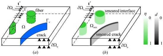
Figure 1.
Representation of the crack in an (a) explicit and (b) diffused manner [].
The phase-field model leads to a system of coupled partial differential equations (PDEs) governing the evolution of displacement and the phase field which are typically solved using numerical techniques []. However, a generalized phase-field model applicable to a wide range of constitutive laws has yet to be established. Additionally, the need for extremely fine meshes in the localization zone makes this method computationally demanding []. Adaptive mesh refinement (AMR) techniques alleviate this cost by concentrating the fine mesh resolution only in the narrow damage (process) zone while maintaining a much coarser mesh elsewhere []. These methods refine the mesh dynamically where the phase field or crack-driving energy is high, e.g., in the vicinity of an evolving crack, and leave the mesh coarse in relatively undisturbed regions. Common strategies include h-adaptivity, p-adaptivity, and combinations thereof (hp-adaptivity) [,,]. In many schemes, a two-stage (global/local) process is used: a coarse global solution identifies active crack regions which are then refined and resolved on a finer mesh []. As a result, AMR preserves accuracy in the fracture zone while drastically reducing total degrees of freedom.
In contrast to the phase-field model, the mixed strain/displacement finite element method (MFEM) [] offers a more efficient and versatile alternative. Unlike PFM, which requires highly refined meshes—typically 10 to 30 elements across a crack—to accurately capture fracture behavior, MFEM achieves comparable accuracy with only about three elements across the crack. This substantially reduces computational expense, making 3D applications more feasible. Additionally, MFEM maintains full generality in constitutive modeling, allowing straightforward incorporation of orthotropic behavior and irreversible strains, whereas PFM relies on a single isotropic damage index with limited constitutive capabilities. As computational demands continue to shape the practicality of fracture modeling techniques, the efficiency and flexibility of MFEM position it as a superior approach, particularly for large-scale and complex structural applications.
To represent discontinuities in materials without relying on spatial derivatives, an alternative approach involves reformulating the equation of motion as an integro-differential []. This concept, introduced by Silling [] under the framework of peridynamics (PD), provides a robust method for addressing mechanical problems involving discontinuities, such as cracks and interfaces. Unlike classical continuum mechanics, PD theory enables each material point to interact with its neighbors within a defined horizon through bonds [,,]. These bonds capture internal force densities and inherently accommodate damage within the medium. Figure 2 briefly represents how the PD method works. If an object occupies a spatial domain at a given time t, the the peridynamic theory assumes that every material point within interacts with other material points located within a certain neighborhood, denoted as . This interaction region, commonly referred to as the horizon, is typically a circular or spherical area characterized by a radius . All material points within this horizon are called the family points of . The interactions between these points form the foundation for defining mechanical behavior under the peridynamics framework [].
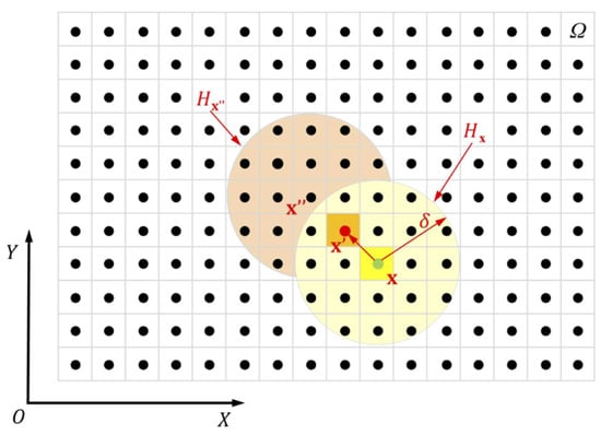
Figure 2.
Discretization of the medium in the PD method considering a specific horizon [,].
PD has been successfully applied to different mechanical problems, including plasticity [,], viscoelasticity [], and thermomechanics [], and its evolution has introduced multiple formulations to address the limitations of the original formulation, which is constrained by a fixed Poisson’s ratio and inability to separate distortional and volumetric deformations. State-based PD (SBPD) generalizes the framework to overcome these challenges by incorporating a modulus state to handle nonlinear and incremental deformations [,]. For greater flexibility, the nonordinary state-based PD (NOSBPD) approach integrates traditional constitutive models into the PD framework, though it faces unresolved issues related to material stability [,]. These advancements highlight the continuous effort to refine PD models for diverse material behaviors.
Within the explicit simulation schemes, the extended finite element method (XFEM) can be considered a procedure that does not require any re-meshing processes []. In the XFEM, the effect of the crack on the strain and displacement field is reflected in the element formulation, and hence, the geometry and mesh remain unchanged. The method builds upon the traditional finite element method, distinguished by its ability to accommodate discontinuities within an element by enhancing the degrees of freedom with specialized displacement functions []. Several techniques, regarded as variations or equivalents of XFEM, have been proposed using the principles of discontinuous functions []. Examples include the phantom node method (PNM) [,,], the augmented finite element method (A-FEM) [,], and the floating node method (FNM) [,]. Although XFEM is widely acknowledged to be a sophisticated technique with a clear advantage in modeling the initiation and progression of cracks along arbitrary, solution-dependent paths [], it does have certain limitations. These include a relatively high computational run-time, challenges with convergence, and the need for significant modifications to the finite element code, such as the incorporation of tracking techniques. Additionally, it struggles to effectively handle scenarios involving crack branching and merging [,].
The cohesive zone model (CZM) is a widely used explicit meso-scale approach for simulating intra-layer damage through a cohesive formulation which captures the nonlinear interfacial softening behavior through a traction–separation law (TSL), as depicted in Figure 3, and mitigates issues with high-stress gradients at the delamination front []. CZMs effectively handle the nonlinear zone ahead of the crack tip, accommodating phenomena like plasticity and micro-cracking without requiring refined mesh configurations []. Initially developed to model energy dissipation rates [], CZMs are capable of simulating damage initiation, propagation, and interactions, such as delamination coupled with matrix cracking []. By modeling the fracture process as a transition from an intact material to a completely broken one, CZMs operate independently of the bulk material’s mechanical behavior [] and are easily implemented in conventional finite element codes []. They provide a simplified and effective means to define crack growth paths by applying the traction–separation law to cohesive elements along the crack path.
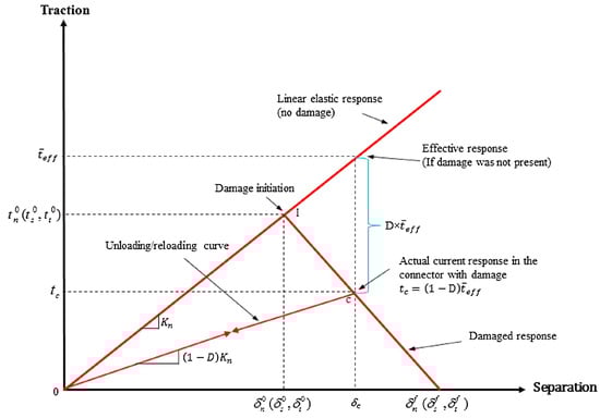
Figure 3.
Traction–separation law within the cohesive zone model [].
CZMs, while effective, face several limitations that affect their applicability. A key challenge is the need for dedicated surface or volume elements at ply interfaces, which can complicate implementation and increase computational runtime due to potential convergence issues. The thickness of the cohesive layer also critically influences the results []. Additionally, CZMs require the crack path to be predetermined and aligned with the fiber direction, which complicates mesh generation []. For composites with numerous layers, incorporating cohesive elements at every interface becomes time consuming and impractical. The traction–separation law used by CZMs can introduce artificial stiffness reductions in the elastic domain, altering the bulk structural response before any damage occurs []. Moreover, the penalty stiffness parameter in TSLs often requires ad hoc calibration, making it problem dependent and nontrivial to determine [,].
In addition to the simulation methods, various computational tools have been employed, each offering distinct capabilities and levels of feasibility depending on the complexity of the modeled phenomena. MATLAB, for instance, is widely used for prototyping numerical algorithms and implementing reduced-order models (ROM) due to its high-level programming environment and integration with toolboxes such as Partial Differential Equation Toolbox and Simulink []. However, for high-fidelity simulations of damage evolution in composites, especially those involving progressive failure, mesh dependency, and nonlinear constitutive models, finite element packages such as ABAQUS (Version 2022), ANSYS (Version 2023 R1), and LS-DYNA (Version R13.0) are more frequently utilized. ABAQUS, in particular, has proven effective due to its user subroutine capabilities, e.g., UMAT, VUMAT, which allow for custom material modeling, such as CZM and CDM [,]. LS-DYNA is also frequently employed for dynamic damage simulations due to its explicit solver, which handles high strain-rate problems and complex contact interactions effectively []. Moreover, emerging data-driven methods and hybrid approaches are increasingly being integrated into simulation workflows using Python (Version 3.9), TensorFlow (Version 2.8), or MATLAB (R2022b), enhancing model calibration and uncertainty quantification []. The feasibility of these tools is not only demonstrated by their widespread use in academia and industry but also by extensive validation through experimental correlation and peer-reviewed benchmarking studies [,,,].
In summary, the simulation of damage in materials, particularly composites, requires advanced numerical techniques capable of capturing complex failure mechanisms. Various modeling approaches, including smeared and explicit representations, have been explored to address the challenges of crack initiation, propagation, and interaction. While smeared methods like CDM and PFM provide a distributed representation of material degradation, explicit methods such as peridynamics (PD), XFEM, and CZM enable the direct modeling of discontinuities. Each technique offers unique advantages and limitations, necessitating careful selection based on the problem at hand. Future advancements will likely focus on improving computational efficiency, enhancing model accuracy, and integrating multiscale approaches to better capture real-world material behavior.
3. Damage Modeling in Composites
Composite materials exhibit distinct damage mechanisms under varying loading conditions, necessitating tailored simulation approaches. Under monotonic loading, damage typically initiates with matrix cracking in off-axis plies followed by fiber breakage and delamination. Daniel and Lee [] identified three characteristic stiffness ranges in cross-ply graphite/epoxy laminates: an initial linear elastic phase, a stiffness degradation phase due to transverse matrix cracking, and a final phase leading to ultimate failure governed by fiber breakage. Under cyclic loading conditions, however, fatigue damage in fiber-reinforced composites initiates with matrix microcracking, fiber/matrix interface debonding, and fiber breakage, progressing to delamination and eventual structural failure. This degradation typically follows a three-stage stiffness reduction: an initial phase with minor stiffness loss due to microcrack formation, a gradual degradation phase with slow damage accumulation, and a final phase characterized by rapid stiffness decline leading to catastrophic failure [,,]. Numerical models, such as CDM and CZM, have been developed to simulate these fatigue processes, incorporating factors like stress amplitude, mean stress, and residual stresses to predict damage initiation and progression [].
In addition, impact loading also introduces complex damage patterns due to high strain rates. Low-velocity impacts, for instance, can cause matrix cracking, fiber breakage, and interlaminar delamination [,,,,,], while high-velocity impacts, such as ballistic strikes, can result in severe damage, including penetration and extensive delamination [].
In contrast, creep damage arises under sustained loads at elevated temperatures, leading to time-dependent deformation. In fiber-reinforced composites, creep mechanisms include longitudinal matrix cracks, transverse shear failure, and local twisting of the fibers []. Modeling creep behavior often employs viscoelastic constitutive models, micromechanical approaches, and homogenization techniques to capture the time-dependent response accurately [,].
3.1. Intra-Layer Damage Modeling
The study of intra-layer damage in composite materials can be approached from different scales, primarily categorized into micro-mechanical and macromechanical models. The fundamental difference between these approaches lies in how the composite is treated. Micro-mechanical models analyze the composite at the level of its constituent materials, focusing on the inherent heterogeneity of the resulting material. In contrast, macromechanical models treat the composite as a homogeneous, orthotropic continuum, capturing the global response rather than local heterogeneities. This duality in composite modeling results in a variety of techniques, each with specific strengths and limitations in terms of accuracy, computational cost, and applicability range.
3.1.1. Micro-Mechanical Models
Intralaminar damage modeling is pivotal for understanding failure mechanisms in composite materials, which are integral to high-performance applications in aerospace, automotive, renewable energy, and structural engineering.
In the last five years, several studies have been published in this direction with varying levels of complexity.
Specifically, the study proposed by Chen and He [] introduces a hierarchical homogenization framework combining finite-volume direct averaging micromechanics (FVDAM) with ABAQUS/CAE to simulate elastoplastic and ductile damage in unidirectional B/Al composite laminates under tensile and shear loading. The model uses plasticity and continuum damage mechanics, implemented as a user material subroutine (Meta-UMAT), to predict nonlinear behavior and microscale stress/damage distributions. Validation against experimental data shows accurate stress–strain responses and computational efficiency, with potential for design applications. The approach is achieving simulations in 13–78 s.
Targeting dynamic effects, Larsson [] and Singh []’s work employs computational homogenization with a VUMAT subroutine in ABAQUS to study dynamic compression failure in UD composites. It models a viscoelastic–viscoplastic matrix with elastic fibers, focusing on shear and kinking. Validated against dynamic stress–strain data, it targets crash simulation applications. The approach captures rate-dependent behavior effectively, balancing efficiency with dynamic detail.
An interesting perspective is the one proposed by Hu et al. []. This paper develops a 3D peridynamic model to study damage in short-fiber and woven composites, supporting mixed stress–strain boundary conditions. Applied to short-fiber (15% fiber volume) and woven (51.97% fiber volume) microstructures, it predicts elastic properties and progressive failure, e.g., debonding, fiber pull-out, and trellising, and is validated against FEA and DIC experiments. The model’s single-load-case capability enhances multiscale efficiency, revealing detailed crack propagation.
Hessman et al. [] proposes a mean field homogenization model for high cycle fatigue (HCF) in short glass fiber reinforced PA66, incorporating fiber and matrix damage. Fiber damage uses a Weibull–Tsai–Wu criterion, while matrix damage includes a novel fiber-coupled progressive law, implemented in a cycle-based FEA framework. Validated with tensile and fatigue tests across fiber fractions (15–50%), it captures orientation-dependent failure and stress concentrations, suitable for industrial applications.
Naderi and Iyyer’s study [] targets the mechanisms governing damage evolution in thin-ply carbon fiber-reinforced laminates subjected to transverse tensile loading, focusing on the influence of 90° ply thickness—spanning 30 m to 120 m—within a [0//0] configuration. Utilizing a three-dimensional micromechanical framework integrated with the augmented finite element method (AFEM), they model a 90° ply constrained between two 50 m 0° plies, where fibers and matrix exhibit isotropic elastic behavior, and fiber–matrix interfaces are governed by a cohesive traction–separation response. Their analysis reveals that damage initiates predominantly through fiber–matrix debonding, subsequently triggering matrix crack propagation and kinking, with visualizations of damage contours and crack trajectories elucidating these processes over precise numerical quantification. Thinner 90° plies demonstrate a pronounced suppression of matrix cracking, attributed to in situ constraint effects, while stochastic fiber arrangements, variable interface toughness, and the presence of voids introduce heterogeneity, altering stress distributions and crack initiation loci in a manner resistant to strict empirical measurement. Emphasizing qualitative insights into failure progression, the authors underscore the need for future investigations incorporating experimental validation, process-induced residual stresses, and additional loading regimes such as compression and shear to further elucidate thin-ply laminate degradation mechanisms.
Kovačević et al. [] develops an analytical micromechanical model for unidirectional (UD) carbon/PEEK composites under cyclic loading, unifying creep and fatigue behavior. It uses a two-scale temporal framework with time homogenization, incorporating matrix viscoplasticity (via the Eindhoven glassy polymer model) and cohesive microcracking, while treating fibers as elastic. Validated against S–N and S–t curves, it captures frequency-dependent failure transitions but struggles with load ratio (R) and off-axis angle effects.
Khansari et al. [] presents the Damage Zone Micro-Mechanical Criterion (DZMC) for orthotropic UD composites under mixed mode I/II loading. It models the damage zone as randomly oriented elliptical microcracks using a probabilistic, semi-empirical image processing approach. Validated with epoxy resin tensile tests, it excels in predicting quasi-brittle fracture but faces mesh sensitivity at certain angles.
The work by Zheng et al. [] introduces a multiscale damage model for 3D woven composites with angle-interlock architecture under warp tension. Using microscale and mesoscale RVEs, it employs the micromechanics of failure Mori–Tanaka mean field (MMF) theory and incorporates Weibull-distributed fiber strength. It focuses on matrix cracking and tortuosity, validated with stress–strain curves. Implemented in ABAQUS, it predicts stiffness and strength accurately (errors 3–5%) but overlooks microstructural imperfections.
Employing the parametric high-fidelity generalized method of cells (PHFGMC) with phase-field damage, Meshi et al. [] model UD CFRP under static loading. Their study focuses on flexible crack paths calibrated against experimental stress–strain curves. The study captures brittle failure and interface debonding but notes RVE size–toughness discrepancies.
The study by Wu et al. [] models SiCp/AZ91 metal matrix composites (MMCs) under tensile loading using the conventional theory of mechanism-based strain gradient (CMSG) plasticity. It couples matrix damage, interface debonding, and particle fracture in a 2D FEA framework (ABAQUS/Explicit). Validated with tensile tests, it highlights interface-dominated failure and strain gradient effects, suggesting 3D extensions.
Qu et al. [] explores the impact of ply orientation and loading conditions on intralaminar and interlaminar damage in composite laminates, integrating 3D two-layer representative volume elements (RVEs) with in situ experimental validation to improve failure mechanism understanding for material design. Using RVEs (RVE00, RVE45, RVE90), they model elastic fibers, elastic–plastic matrices with ductile damage, and cohesive interfaces under transverse tension, through-thickness compression, and out-of-plane shear, validated by force–displacement curves and SEM/optical imaging of orthotropic laminates. Findings reveal that transverse tension initiates interfacial microcracks evolving into fiber-parallel matrix cracks, with RVE45 delaying delamination via fiber rotation and RVE90 showing extensive matrix damage. Compression induces ductile matrix damage and angled fracture planes in RVE00, redirected intralaminarily in RVE45/RVE90, and shear causes delamination from intralaminar cracks migrating to resin-rich zones. Key insights highlight ply orientation’s role in microcrack-triggered delamination, introducing the “delamination plane” concept, with simulations matching experimental fracture patterns, demonstrating the multi-layer RVE’s efficacy in guiding multiscale modeling and enhancing crack resistance through interfacial bonding optimization.
Varandas et al. [] propose a 3D micromechanical framework to estimate the mode I through-thickness intralaminar R-curve of unidirectional CFRPs, focusing on fracture toughness and fracture process zone length using finite element models of geometrically scaled single-edge notch tension specimens combined with the size effect method. The FE models integrate microscale regions: elastic fibers, elasto-plastic matrix damage via VUMAT in ABAQUS/Explicit, and cohesive fiber–matrix interfaces and mesoscale homogenized outer plies, incorporating ±30% variability in matrix/interface properties to simulate 3D effects, with peak loads across specimen sizes (5–40 mm) and fiber volume fractions (35–71%) analyzed to derive steady-state toughness and fracture process zone length. Results show steady-state toughness (exceeding that of neat epoxy due to fiber bridging) and fracture process zone length both increasing with interface toughness and fiber volume fraction, driven by matrix plasticity, interface debonding, and bridging, as validated by SEM. The study underscores the matrix-dominated crack propagation and the significant influence of interface properties and fiber content, though it lacks fiber damage modeling and relies on macromechanical matrix assumptions, offering a robust tool for R-curve prediction and damage model calibration while highlighting the need for improved interface characterization.
In their work, Wani and Daggumati [] explore damage initiation and progression in a unidirectional non-crimp fabric (NCF) glass fiber-reinforced polymer (GFRP) composite ply under transverse tension and compression and use a detailed computational micromechanical model to reveal how microscale features shape macroscopic behavior. They propose a 3D RVE that weaves together axial and backing fiber bundles, an epoxy matrix, small voids, and subtle fiber waviness, portraying fibers as elastic yet breakable. The matrix is flexible with a pressure-sensitive twist, and interfaces are fragile bonds governed by cohesive rules, all validated through hands-on experiments with digital image correlation (DIC). Their findings show that, under tension, damage initiates at the fiber–matrix boundary, propagates through peeling interfaces and a yielding matrix, and ends with the snapping of backing fibers, where voids and waviness noticeably weaken the material. Under compression, it initiates with interface cracks, followed by matrix softening and the formation of shear bands, and ends with backing fiber collapse, again tempered by defects. This work underscores the role of interface breakdown and microstructural particularities such as voids and waviness in driving damage.
Sagar et al. [] propose a thermodynamically consistent PFM for elastoplastic continua, specifically targeting the micromechanical analysis of ductile fracture within the epoxy matrix of FRP composites with an emphasis on elucidating pressure-sensitive plastic deformation and stress-state-dependent failure mechanisms. The methodology integrates a novel phase-field driving energy formulation incorporating a local damage propagation indicator and an energy barrier associated with damage initiation and regularization. Fibers are modeled as linear elastic, the epoxy matrix employs a Drucker–Prager plasticity framework with isotropic hardening, and fiber–matrix interfaces are governed by CZM utilizing Benzeggagh–Kenane (BK) criteria. This is implemented within a 3D microstructural volume element (MVE) featuring stochastic fiber distribution, subjected to transverse tensile loading via FEA, and is validated through analytical 1D studies and numerical benchmarks against established literature. Findings delineate a sequential damage evolution under transverse tension: initial interface debonding post-elastoplastic deformation precipitates matrix cracking, coalescing debonded regions into a primary vertical crack accompanied by secondary microcracks, with crack morphology modulated by fiber spatial arrangement and MVE dimensions, corroborated by homogenized stress–strain responses aligning with reference data. The model’s efficacy lies in its capacity to capture the epoxy’s ductile fracture characteristics, leveraging pressure sensitivity and stress-state dependency to enhance predictive fidelity without necessitating discrete crack tracking, thus surpassing conventional methodologies such as CZM or XFEM and offering a robust computational tool for FRP strength prognosis and broader elastoplastic fracture investigations.
When looking at the global picture across all these studies, matrix cracking and fiber–matrix interface failure are universal, reflecting the intralaminar focus in composite failure. Chen and He [] model elastoplastic matrix damage, Singh et al. [] emphasize matrix shear and kink-band formation, and Sagar et al. [] focus on ductile fracture. This consistency spans UD, e.g., [,], NCF [], and FRP [] systems, underscoring a shared foundation.
With respect to constituent-level material modeling, fibers are typically elastic, e.g., [,,], while matrices vary: elastic [], elastoplastic [,,,], viscoelastic–viscoplastic [,,], pressure-dependent [,,], or strain gradient-dependent []. Damage evolution is a shared focus, with mechanisms like fiber bridging [], shear bands [], crack linking [], or kink-bands [] enhancing resistance.
The recent works analyzed collectively affirm the pivotal role of micromechanical modeling in elucidating intralaminar damage mechanisms within composite materials. These studies converge on a unified approach: employing constituent-scale analyses via RVEs or microstructural volume elements (MVEs) to dissect the complex interactions of matrix cracking, fiber–matrix interfacial decohesion, and progressive damage under a spectrum of mechanical stimuli, including static tension, dynamic compression, and cyclic fatigue. Methodological diversity is pronounced, spanning finite element methodologies—e.g., the augmented finite element method, phase-field fracture, and computational homogenization—analytical formulations, and peridynamic simulations together with probabilistic frameworks, each tailored to specific composite architectures—unidirectional (UD), non-crimp fabric (NCF), woven, or metal matrix composites (MMCs)—and damage modalities, such as kink-band formation, ductile matrix failure, or fiber bridging.
Validation approaches integrate qualitative assessments, such as crack trajectory visualization [], with quantitative metrics, including stress-strain responses [,] and in situ imaging data [], achieving error margins of 2–10% where robust experimental benchmarks exist, though limitations in direct experimental corroboration, e.g., [], and computational scalability, e.g., [,], persist.
These models collectively demonstrate that intralaminar damage is intricately governed by microstructural heterogeneities such as fiber spatial distribution, interfacial constitutive properties, and inherent defects. Unresolved challenges include the incorporation of process-induced residual stresses, fiber rupture mechanics, and standardized validation protocols across loading regimes.
3.1.2. Macromechanical Models
In macromechanical modeling, the composite material is represented by a RVE []. This unit cell concept allows for the description of the composite as a homogeneous material, whose behavior replicates that of the heterogeneous composite structure when repeated in space. Consequently, macromechanical approaches are commonly referred to as homogenization models, as they focus on the equivalent material properties derived from the RVE.
Under elastic conditions, the characterization of this equivalent material involves determining the nine independent components of the orthotropic constitutive tensor. Experimentally, this is achieved by measuring the elastic moduli (, , ), shear moduli (, , ), and Poisson’s ratios (, , ) that define the composite’s mechanical response. These properties correspond to a specific composite configuration, meaning that variations in fiber orientation, volume fraction, or constituent materials result in different material properties. This is particularly important, as manufacturing processes can introduce deviations in fiber orientation or volume fraction [,], making laboratory-measured properties potentially non-representative of the final composite structure. Consequently, while macromechanical models offer simplicity compared to micromechanical approaches, they are often rigid, requiring recalibration when material composition changes.
The experimental determination of these mechanical properties is typically performed following standardized testing procedures outlined in guidelines such as those provided by ASTM (American Society for Testing and Materials) and ISO (International Organization for Standardization). For example, ASTM D3039 [] describes the tensile testing of polymer matrix composites, ASTM D3518 [] focuses on in-plane shear response, and ASTM D5379 [] provides guidelines for measuring shear properties using the V-notched beam method. These standardized protocols ensure the reliability and repeatability of material characterization, which is critical for accurately defining input parameters in macromechanical models [].
Numerous studies have employed macromechanical models to simulate the elastic and inelastic behavior of fiber-reinforced polymers (FRPs). Following this approach, several models have been developed to incorporate effects such as loading rate dependency [,], which is critical for thermoplastic-matrix composites and cyclic loading responses [,], including frequency and stress ratio effects.
To address the rigidity associated with macromechanical models, some researchers have adopted meso-scale modeling approaches [,,,]. These models share the philosophy of macromechanical homogenization but focus on the response of individual laminate plies rather than the composite as a whole. In this framework, material behavior is defined phenomenologically based on strain distribution rules among the plies. As with macromechanical models, extensive experimental data are required to characterize ply behavior accurately. For instance, Llobet et al. [] introduced a meso-scale model for studying damage evolution in laminates under cyclic loading. Their approach required the identification of 14 parameters to characterize intralaminar damage under both elastic and inelastic conditions, including stiffness, strength, and fracture toughness. However, just as in macromechanical modeling, changes in laminate composition necessitate recharacterization, incurring significant experimental costs.
Another important category within homogenization models is based on mixture theories. Originally formulated by Truesdell and Toupin [] and later adapted by Reuss and Voigt for composite materials [], these homogenization rules serve as constitutive frameworks to define the overall response of the composite. In some cases, these models are coupled with meso-scale formulations to phenomenologically describe the interaction between different layers of the composite []. Alternatively, they can be employed as standalone models to derive the macroscopic response directly from the behavior of the constituent materials [,,,,,].
One notable development in this area is the series-parallel mixing theory, introduced by Oller [,] for modeling fiber-reinforced composites. This model captures the orthotropic response of the composite by assuming iso-deformation along the fiber direction and iso-stress in the transverse direction. A key advantage of this approach is that its calibration is directly linked to the properties of the constituent homogeneous materials, making it less sensitive to variations in fiber volume fraction or orientation. This significantly reduces the experimental effort required for material characterization, offering a flexible alternative to conventional homogenization methods.
3.1.3. Multiscale Models
The previous phenomenological approaches describe the mechanical response of composite materials only at the macroscopic level. This is really efficient from a computational point of view, enabling the analysis of large-scale structures. However, its accuracy is compromised when complex interactions between the different components of a composite material take place. The introduction of more complex composites, such as CFRP’s [,,,,], nanofibers [,,], carbon nanotubes (CNTs) [,], short fiber reinforced concrete [], or masonry [,,], or composites that are additively manufactured [,,] required the development of more sophisticated numerical techniques for their analysis.
With the advancement of computational power, multiscale homogenization methods have emerged as a viable approach for analyzing composite materials. These methods compute the stress–strain response at each macroscopic integration point by solving an RVE or unit cell, which is modeled as an independent subproblem. To ensure the validity of this approach, a clear scale separation between the macrostructure and microstructure must be maintained (see Figure 4), as well as its periodicity [].
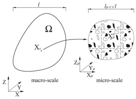
Figure 4.
Separation of scales in a multiscale approach. Source: Otero [].
The RVE serves as a geometric and mechanical representation of the microstructure subjected to the macroscopic deformation gradient. Among the various multiscale techniques, the first-order multiscale method () [,,,,,,,,,] is the most widely adopted. In this framework, the macroscopic behavior is determined solely by the first gradient of the displacement field, allowing for the homogenization of material properties based on microscale computations. This multiscale method leverages the macroscopic strain tensor as an input of the microscale problem. The overall composite behavior is expressed as the macroscopic stress–strain relationship through an explicit representation of the internal heterogeneous structure within an RVE. A key advantage of this approach is that it does not rely on predefined constitutive assumptions or compatibility equations for the composite material. Instead, the macroscopic response naturally emerges from the microscale solution after a proper up-scaling is performed. Additionally, this method imposes no restrictions on the constitutive laws governing the individual constituents, allowing for the inclusion of non-linear behaviors and time-dependent effects such as damage, viscoelasticity, or plasticity. This flexibility makes the approach particularly suitable for studying composites with complex and evolving material properties.
The fundamental principles of classical first-order computational homogenization can be described using the four-step homogenization scheme introduced by []:
- Define an RVE of the microstructure, where the constitutive behavior of each individual constituent is known.
- Apply the macroscopic strain as displacement boundary conditions on the RVE, establishing the macro-to-micro transition.
- Compute the macroscopic stress by analyzing the deformed microstructural RVE, enabling the micro-to-macro transition.
- Derive the numerical relationship between the macroscopic input and output variables, effectively linking the microscale and macroscale behaviors.
Numerous studies have demonstrated that can effectively model both linear and nonlinear RVEs, enabling the simulation of complex material behaviors. The computational homogenization technique offers several key advantages []:
- No explicit assumptions about the macroscopic local constitutive response are required, as it is naturally accounted for by the resolution of the microscale boundary value problem (BVP).
- The macroscopic constitutive tangent operator is directly obtained from the microscopic stiffness matrix via static condensation.
- The scale transition ensures consistency throughout the analysis and in terms of energy dissipation.
- The method seamlessly accommodates large strains and large rotations, provided that the microstructural constituents can be modeled with a geometrically nonlinear framework.
However, this methodology comes with a significant computational burden, as a microscale problem must be solved at each macroscopic integration point. Consequently, efficient numerical strategies, parallel computing, and reduced-order modeling [,] techniques are often employed to mitigate the computational cost while maintaining accuracy. In this regard, several ROM techniques have been developed, such as the response surface models (RSM) [] and proper orthogonal decomposition (POD) [], among others [,].
In problems involving localized deformations, fracture typically affects only a small region of the structure (i.e., strain localization), while most of the material remains in the linear-elastic regime. This observation suggests that solving a full RVE problem at every macroscopic integration point may be unnecessary, leading to the development of more efficient multiscale strategies. One such approach is the use of nonlinear activation functions, as proposed by Otero et al. []. This method defines an activation criterion based on the maximum elastic energy density that an RVE can sustain before failure. When the material remains within the elastic threshold, homogenized properties can be used directly, bypassing computationally expensive RVE calculations. This results in a substantial reduction in computational cost while maintaining accuracy in critical regions. However, a key limitation of this approach is that any modification at the macroscopic level necessitates a re-evaluation of the nonlinear activation function, even when using the same RVE. This introduces additional computational overhead in cases where frequent updates are required, making it less efficient for simulations with evolving boundary conditions or progressive damage.
As a natural extension of the first-order homogenization method, second-order computational homogenization [,] was introduced in the last decade to address regions of intense deformation. This approach is particularly relevant when the characteristic wavelength of the macroscopic deformation field is comparable to the microstructural length scale. Unlike first-order homogenization, where only the macroscopic strain is passed to the RVE, the second-order method also incorporates the macroscopic gradient of the strain into the microscale equations. Consequently, while the first-order equilibrium problem remains unchanged at the microscale, a higher-order equilibrium problem emerges at the macroscale. Despite its advantages in capturing localization effects and nonlinear behavior, second-order homogenization has seen limited widespread application due to its complex FE implementation. In contrast, first-order homogenization retains first-order equilibrium equations at both scales, making it computationally more efficient and easier to implement. As a compromise between these two approaches, an enhanced first-order method [] could provide a practical alternative. By incorporating macroscopic second-order deformation measures into the microscale boundary value problem, this approach aims to account for second-order effects while maintaining the relative simplicity of first-order formulations.
In conclusion, while multiscale methods offer an accurate and rigorous framework for capturing the behavior of heterogeneous composite materials, their high computational cost poses a significant challenge, particularly for large-scale geometries. Nevertheless, continuous advancements in computational power, enhanced parallelization strategies, and the integration of machine learning or surrogate modeling techniques for microscale computations are progressively alleviating these limitations (see Section 4). These developments pave the way for a broader and more efficient application of multiscale approaches in engineering practice.
3.2. Inter-Layer (Delamination) Damage Modeling
Delamination in laminated composite materials represents a critical failure mode that significantly influences structural integrity and load-bearing capacity [,,,,]. This damage mechanism arises due to the weak bonding between adjacent plies, as composites generally lack through-thickness reinforcement [,]. Delamination can be triggered by various factors, including cyclic loading (fatigue), impact damage, and residual stresses generated during the manufacturing process []. If left unaddressed, delamination can propagate through the structure, ultimately leading to loss of stiffness and potential failure.
Traditionally, the modeling of delamination progression is divided into two main stages: initiation and propagation. Several numerical techniques have been developed to capture these phenomena. One of the earliest and least computationally expensive methods is the element erosion approach in which elements are removed from the mesh once their failure threshold is reached [,]. This method ensures numerical stability by gradually reducing the load-bearing capacity of elements over multiple load increments rather than removing them instantly. Often employed in conjunction with CDMs, element erosion is particularly useful for simulating ductile fracture []. However, some implementations rely solely on a failure criterion without incorporating the softening behavior of materials. While straightforward to implement, this technique is sensitive to mesh size and element shape, potentially leading to non-physical results.
A more advanced technique that addresses some of these limitations is the XFEM, which allows cracks to initiate and propagate along solution-dependent paths without requiring predefined crack locations []. Several studies have integrated XFEM with other modeling approaches to enhance accuracy and computational efficiency. For instance, XFEM has been coupled with the CZM to simulate the interactive progression of matrix cracks and delamination, enabling a more comprehensive representation of failure mechanisms in composite structures [,]. This combination is particularly effective in modeling progressive damage, as XFEM captures matrix cracking, while CZM handles delamination propagation [], as illustrated in Figure 5. Additionally, a crack-leading model implemented in ABAQUS successfully characterized different delamination morphologies and interactions with matrix cracks, yielding numerical results that closely align with experimental observations []. Further improvements include XFEM-based models designed to capture the zigzag delamination growth path using quadratic crack initiation criteria and principal stress-based propagation direction, making them suitable for accurately predicting complex delamination behavior [].
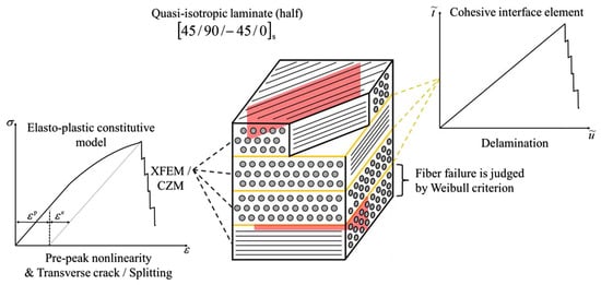
Figure 5.
Coupling XFEM with CZM for the modeling of matrix cracking and delamination, respectively [].
XFEM has also been applied to various material systems and test configurations, demonstrating its versatility. For example, it has been utilized to analyze delamination in fiber–metal laminates, marking one of the first instances of its application in GLARE composites []. Similarly, the method has been evaluated in traditional carbon fiber-reinforced polymer (CFRP) laminates, where it showed high accuracy in mode I fracture predictions but required fine meshing to address convergence issues []. XFEM has further been employed in fatigue modeling, where it has been combined with VCCT to predict energy release rates at disbond crack tips in bonded composite-metal joints []. The method has proven effective in high cycle fatigue simulations, incorporating a phantom node approach for mesh-independent crack insertion and integrating fatigue-cohesive zone formulations for progressive failure analysis [,,]. Moreover, a coupled XFEM-VCCT approach has been proposed for mode I fatigue delamination modeling, demonstrating reduced computational costs compared to conventional techniques while maintaining high accuracy []. The integration of XFEM with cohesive elements has also enabled the prediction of fatigue-driven multi-crack evolution in laminated composites under mixed-mode loading, further enhancing its capability in damage modeling [].
The XFEM approach enhances modeling flexibility but introduces challenges related to computational cost, convergence difficulties, and complex tracking algorithms. Additionally, XFEM struggles to handle crack branching and merging, further limiting its applicability in highly dynamic failure scenarios [,].
Another emerging approach for delamination modeling is the PFM, which formulates crack propagation as a diffused interface problem based on energy minimization principles []. PFM has gained significant attention for modeling delamination in composite laminates due to its ability to capture complex crack paths without requiring predefined crack surfaces or tracking algorithms. Unlike conventional methods, PFM modeling introduces a gradient-enhanced damage formulation based on Griffith’s theory of fracture, allowing for the simulation of intralaminar and translaminar fracture in long fiber composites [], as depicted in Figure 6. This approach provides robust predictions under quasi-static loading while minimizing mesh dependency, making it a compelling alternative to classical fracture mechanics models [].
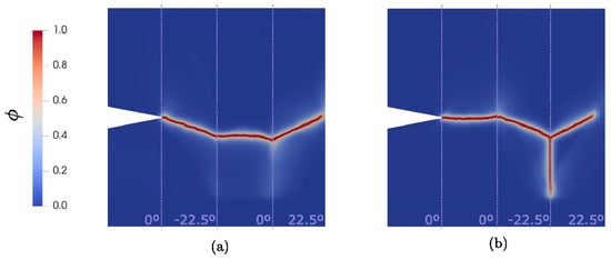
Figure 6.
The failure pattern obtained through the PF approach in two different configurations of (a) and (b) [].
To address delamination migration and mixed-mode failure, a mixed-mode phase-field formulation has been developed, incorporating volumetric and deviatoric effects along with a power law-based delamination criterion. This formulation has demonstrated accuracy in predicting delamination kinking, migration, and crack path evolution, closely matching experimental observations [], as presented in Figure 7.
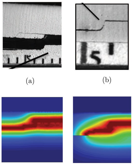
Figure 7.
Interfacial crack migration in experiments and obtained phase field results in two different geometrical configurations where the point of load application is (a) on the right side and (b) on the left side of the notch [].
Moreover, a unified phase-field-cohesive zone model (PF-CZM) has been introduced to predict bulk fracture and interfacial delamination in CFRP composites, enabling quasi-brittle failure predictions without requiring an explicit traction–separation law for interfacial cracks. The PF-CZM approach simplifies delamination modeling while inherently capturing material strength, offering an efficient framework for simulating failure in fiber-reinforced composites [].
The integration of PF with advanced numerical techniques has further enhanced its applicability. An isogeometric phase-field model (IGA-PFM) has been proposed to improve computational efficiency and accuracy in delamination simulations, leveraging smooth geometric representations to provide higher sensitivity to laminate stacking configurations []. Additionally, hybrid modeling frameworks combining PF with CZM have been explored to address the intricate interactions between intralaminar and interlaminar failure mechanisms, ensuring thermodynamic consistency and reducing computational complexity []. A phase-field-augmented peridynamics model has also been introduced, eliminating the need for empirical interaction laws and conventional traction–separation models while providing a general framework for delamination tracking under varying boundary conditions []. This PD-PF model offers additional advantages, including the elimination of artificial crack tracking algorithms, enhanced physical realism in fracture propagation, and a natural treatment of different delamination modes without special constraints. Collectively, these advancements highlight the phase-field approach as a versatile and powerful tool for delamination modeling in composite laminates, capable of capturing complex crack interactions, improving numerical stability, and reducing reliance on empirical formulations.
Alongside PFM, FNM has gained attention for its capability to model both matrix cracks and delamination within the same framework []. Unlike traditional finite element-based methods, FNM introduces additional degrees of freedom to capture discontinuities within an element. This method has been integrated into enriched shell finite elements to efficiently simulate delamination migration, combining FNM with VCCT for damage propagation prediction []. The enriched element formulation enables the modeling of arbitrary delamination growth paths and transverse matrix cracking while reducing computational complexity compared to traditional techniques. Furthermore, an alternative approach using virtual embedded cohesive elements has been introduced, where floating nodes automatically generate cohesive elements at the crack tip, allowing for more flexible delamination migration modeling without severe mesh distortions [].
To further enhance computational efficiency, an adaptive floating node method (A-FNM) has been developed, featuring elements that transition between different configurations—refined, coarsened, or master elements—based on the crack propagation state [], as illustrated in Figure 8. This approach allows for local refinement without requiring global remeshing, significantly reducing computational effort while maintaining accuracy in progressive damage simulations.
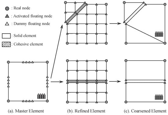
Figure 8.
Adaptive floating node element (a) master element configuration, (b) refined element configuration, (c) coarsened element configuration [].
The fundamental architecture of FNM closely resembles the phantom node method used in XFEM, but it eliminates issues related to crack geometry mapping and integration errors, making it well-suited for modeling complex crack networks in composite laminates []. Additionally, the ability to represent multiple plies, interfaces, and damage interactions within a single element enhances the method’s applicability for composite failure analysis [].
In the context of multiple delaminations, an adaptive floating node formulation coupled with an adaptive refinement scheme (ARS) has been proposed to accurately simulate quasi-static delamination growth while reducing the computational costs associated with cohesive element-based models []. By adaptively updating element interface discretizations, this formulation ensures efficient convergence and improved solution times. Similarly, a hybrid approach that combines FNM with VCCT has been introduced for modeling delamination migration in cross-ply tape laminates, capturing both delamination and matrix cracking within a single element while determining migration onset and path in a mesh-independent manner [].
Beyond quasi-static loading scenarios, FNM has been applied to impact simulations, where enriched shell elements incorporating the method have been used to simulate low-velocity impact damage in composites []. While the current implementation requires a pre-seeded initial crack and is limited to capturing delamination at a single ply interface per element, it demonstrates the potential for computationally efficient impact damage modeling.
The CZM is another widely used approach for modeling delamination in composite materials, addressing damage initiation and propagation through traction–separation laws. One key challenge in CZM implementation is accurately characterizing the traction–separation response (TSR) for mode I delamination. Experimental advancements, such as the composite rigid double cantilever beam (cRDCB) method, now allow direct TSR measurement from a single specimen. However, these TSRs also capture the stiffness contribution of adjacent laminae, introducing artificial compliance in numerical models. To address this, a two-stage analysis procedure incorporating a crack tip compensation function has been proposed, refining TSRs for more accurate mode I delamination modeling []. Similarly, an energy-based CZM approach has been developed for fully uncoupled multi-directional (FUMD) laminates, introducing a single internal variable to govern damage evolution. This method provides a more general constitutive response, ensuring thermodynamic consistency and improving agreement with experimental results [].
Various modifications to CZM have been proposed to enhance its accuracy in different scenarios. For instance, a trapezoidal TSL has been introduced for high-cycle fatigue loading in fiber–metal laminates (FMLs), proving more efficient in predicting delamination growth in ductile adhesives than traditional bilinear CZM []. Similarly, a three-linear CZM, integrating two bilinear laws, has been designed to model mixed-mode delamination with large-scale fiber bridging. This model applies varying bridging strengths along the fracture process zone (FPZ), accounting for geometry-dependent effects []. In fatigue delamination, a novel cyclic cohesive zone model (CCZM) has been proposed, incorporating trilinear traction–separation laws based on the Turon et al. [] and Kawashita–Hallett [] models. This approach enhances accuracy and computational efficiency, particularly in glass/epoxy laminates exhibiting significant fiber bridging []. Additionally, recent advancements in mixed-mode CZM have led to the development of a hybrid approach using linear and torsional spring elements to simulate fracture process zone effects. This method integrates R-curve behavior estimation, allowing accurate prediction of fracture toughness evolution without costly experiments []. These innovations highlight the versatility and ongoing development of CZM in delamination modeling, making it a crucial tool for composite material analysis.
An alternative to explicitly modeling individual cracks is the use of homogenization techniques, which aim to incorporate delamination effects into the bulk composite response without discretizing each ply interface. This method has been developed recently based on a classical mixing theory [], and it is matured by incorporating virtual interfaces and virtual bulk layers, as presented in Figure 9.
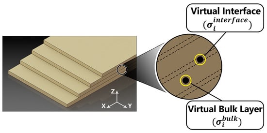
Figure 9.
Virtual bulk layers and virtual interfaces through the homogenized medium [].
Mode I and mode II delamination damages are accounted for independently, and their corresponding interfacial stresses are computed by employing an averaging scheme. A stress-based damage model [] is then considered to compute the inter-layer damage values at each interface. The material behavior in macroscale is well-captured by affecting the associated mode I and mode II stress components at each bulk layer. Figure 10 illustrates the discrete and homogenized configurations along with their corresponding behaviors.
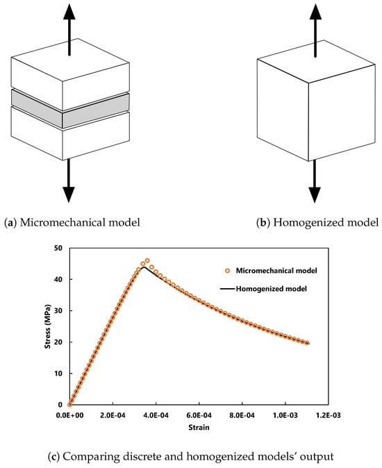
Figure 10.
Modeling debonding between two blocks in (a) micromechanical and (b) homogenized approaches and (c) their corresponding behavior [].
This method has been applied to different loading configurations using standard test specimens, including double cantilever beam (DCB), end notch flexure (ENF), and mixed mode bending (MMB), and good accuracy was obtained compared to other numerical methods and experimental data.
The homogenization method eliminates the need for explicit cohesive elements, thereby reducing artificial stiffness effects and facilitating implementation in large-scale structural simulations. Moreover, the homogenized approach enables the consideration of intra-layer failure mechanisms such as plasticity and matrix cracking, further improving the predictive capability of composite damage models.
The homogenization theory has been further developed into the cyclic loading regime as an efficient way to simulate structural behavior in fatigue conditions []. To achieve this, the crack propagation regime is divided into three distinct stages determined by the maximum stress at the crack tip () relative to the fatigue limit () and the ultimate strength (), as illustrated in Figure 11.
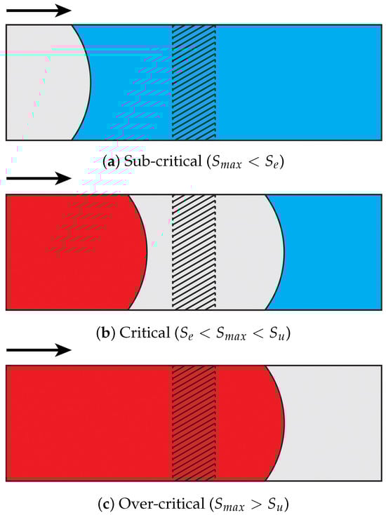
Figure 11.
Different stages experienced by a band of elements in (a) sub-critical (blue), (b) critical (gray), and (c) over-critical (red) regions as a fatigue crack propagates in the direction illustrated by arrows [].
A fatigue reduction function () is incorporated into the formulation to address the effects of cyclic loading, and it is independently developed for each stage of crack propagation. The model can be calibrated by employing the available Wöhler diagrams. A set of standard test procedures has been conducted to evaluate the model performance in both damage initiation and damage propagation stages.
The incorporation of virtual layers and interfaces enhances the efficiency of the proposed model, making it well suited to simulating large-scale structures with multiple layers. This approach also streamlines the preprocessing stage by eliminating the need for a layer-by-layer representation. Furthermore, by calibrating fatigue parameters at a single interface, the model can accommodate various stacking sequences and fiber orientations [].
In summary, while several numerical methods exist to model delamination, each presents its own advantages and challenges. The trade-off between accuracy and computational efficiency remains a key consideration, particularly for large-scale structures with multiple layers. Advances in homogenization techniques offer a promising direction by providing an efficient means of addressing delamination without the complexities associated with explicit interfacial modeling.
Among the methods discussed, continuum damage mechanics (CDM), cohesive zone models (CZM), extended finite element method (XFEM), phase-field models (PFM), and peridynamics (PD) are evaluated for their accuracy in predicting these phenomena. CDM excels in modeling intra-layer damage by representing progressive stiffness degradation through smeared crack approaches, making it effective for capturing crack initiation and propagation under monotonic and cyclic loading. However, its mesh dependency can lead to inaccuracies in crack interaction due to localization issues. PFM addresses this by using a diffused crack representation, offering high accuracy in predicting crack initiation and propagation without requiring explicit crack tracking, as it relies on energy minimization principles. Yet, PFM struggles with crack interaction due to its computational intensity and the need for extremely fine meshes, which can miss complex crack branching scenarios.
XFEM and CZM are explicit methods that directly model discontinuities, providing robust frameworks for crack propagation and interaction. XFEM is particularly accurate for crack propagation along arbitrary paths, as it enhances finite element formulations to accommodate discontinuities without re-meshing, making it suitable for capturing crack initiation and growth in composites. However, its limitations in handling crack branching and merging reduce its accuracy for crack interaction, and it incurs high computational costs due to convergence challenges. CZM, on the other hand, is highly effective for delamination and crack interaction, using traction–separation laws to model the nonlinear behavior at interfaces. It accurately predicts crack initiation and propagation, especially in scenarios involving delamination coupled with matrix cracking, but its accuracy depends on predefined crack paths, which can be a limitation for complex crack interactions. PD offers a unique advantage by reformulating the equation of motion in an integro-differential form, enabling accurate prediction of crack initiation, propagation, and interaction, including complex scenarios like branching, due to its bond-based approach. However, PD’s computational cost is significant, particularly for large-scale problems, as it requires interactions to be modeled within a defined horizon.
Considering accuracy and computational costs, PFM and PD provide high-fidelity predictions but at a steep computational expense. PFM’s need for fine meshes (10–30 elements across a crack) makes it impractical for large-scale simulations, despite its accuracy in crack initiation and propagation. PD, while versatile in handling discontinuities and complex crack interactions, also demands substantial computational resources due to its non-local nature. XFEM, though accurate for crack propagation, struggles with computational efficiency due to the need for specialized displacement functions and tracking techniques, making it less viable for large-scale applications. CZM, while effective for delamination, requires predefined crack paths and cohesive elements at interfaces, increasing computational overhead for multi-layered composites. In contrast, CDM offers a balance between accuracy and computational efficiency, especially for intra-layer damage, as it avoids explicit crack tracking and can be easily implemented in commercial software like LS-DYNA with models such as MAT_22. However, its mesh dependency limits its accuracy for crack interaction, necessitating regularization techniques to mitigate localization issues.
For damage simulation in composites, considering both accuracy and computational costs, CZM is recommended from the methods discussed in the paper. CZM provides a robust framework for simulating delamination and crack interaction, which are critical in laminated composites, with reasonable accuracy in predicting crack initiation and propagation. Its implementation in finite element codes like ABAQUS is straightforward, and it can handle nonlinear interfacial behavior effectively through traction–separation laws. While CZM requires predefined crack paths and can introduce artificial stiffness reductions, these drawbacks are often manageable through careful calibration or employing homogenization theories. For scenarios where computational resources are limited and delamination is a primary concern, at the moment, CZM and homogenization methods strike an optimal balance, offering a practical solution without sacrificing essential predictive capabilities. Table 1 summarizes the methods discussed in this section.

Table 1.
Summary of the main features, strengths, and limitations of numerical strategies for damage simulation in composites.
4. Data-Assisted Composite Modeling
The integration of machine learning (ML) techniques into the analysis of the mechanical behavior of composites has gained significant traction in the field of composite materials, especially in the field of FRPs []. ML-enhanced approaches offer a powerful framework for optimizing and characterizing laminated FRPs, enabling high predictive accuracy while substantially reducing computational costs once trained. This data-assisted paradigm improves both efficiency and insight, facilitating advanced modeling and analysis beyond the limitations of traditional methods, such as classical methods. The interest of the scientific community on this topic is evidenced by a dramatic increase in publications tackling this issue, as can be studied in [].
4.1. Minimal Overview of Machine Learning
ML algorithms can be broadly classified into conventional and unconventional categories. Conventional ML algorithms, including supervised and unsupervised learning techniques, are well established in the field and have been successfully applied to a wide range of problems. These methods are generally straightforward to interpret and implement. In contrast, unconventional ML algorithms represent emerging approaches that are still under active research. Although these methods often require larger datasets and greater computational resources, they have the potential to achieve superior performance in specific applications, albeit at the cost of increased complexity and interpretability challenges.
Within conventional ML, supervised learning [,] is a category of ML that relies on labeled datasets to train models, meaning that both independent and dependent variables are predefined. Within this framework, algorithms are typically classified into two main types: regression, which focuses on predicting continuous values, and classification, which assigns inputs to discrete categories. These methods are widely used due to their ability to learn from existing patterns and make accurate predictions using new data. In this regard, parametric models assume a predefined functional relationship between independent and dependent variables, relying on a fixed set of parameters learned from the training data. The simplest example of this approach is linear regression. A more advanced variant, known as regularization models, incorporates a penalty term into the objective function to mitigate overfitting. Overfitting occurs when a model achieves high accuracy on the training dataset but performs inconsistently on new data, exhibiting low bias but high variance.
The other category of algorithms is supervised classification models, which are ML techniques used to categorize data by identifying the decision boundary that separates different groups of data. Essentially, these models predict a discrete dependent variable based on a set of independent variables, with the threshold value being determined by the decision boundary. Parametric classification models define this decision boundary by assuming a specific functional relationship between the independent and discrete dependent variables. While these models are relatively simple to interpret and perform well with linearly separable datasets, they are sensitive to outliers and exhibit limitations when applied to non-linearly separable data. A well-known example of a parametric model in the literature is logistic regression (LR) [].
Unsupervised learning is an ML approach in which the model works with unlabeled data, which means the dataset does not contain predefined independent or dependent variables. Instead of focusing on predicting specific outcomes, the goal of unsupervised learning is to identify patterns or structures within the data. This category of ML encompasses two main types of algorithms: clustering tasks and dimensionality reduction. In the literature, dimensionality reduction has been particularly useful when combined with other machine learning models. This technique aims to reduce the number of variables in a dataset while preserving the maximum amount of relevant information, thus simplifying the complexity of the data without losing its essential characteristics.
Artificial neural networks (ANNs) [,] are ML models inspired by the structure and function of biological neurons. They typically consist of an input layer, one or more hidden layers, and an output layer. The input layer passes data through the network, where each hidden layer performs computations and introduces non-linearity via activation functions like sigmoid, ReLU, or tanh. The output layer generates the final result, allowing the model to learn complex relationships between input and output. In this case, the learning is translated into a proper calibration of the weights within the network. Shallow artificial neural networks (SANN) use one or two hidden layers. Examples include radial basis function (RBF) networks, which are used for non-linear regression and classification, and multi-layer perceptrons (MLP), which are versatile models for supervised learning tasks such as classification and regression. Deep learning (DL) models, with more than two hidden layers, include deep neural networks (DNNs) and convolutional neural networks (CNNs). DNNs are multi-layered models capable of learning complex non-linear relationships, but they require significant computational resources and large datasets. CNNs, a specific type of DNN, excel in image and video processing by extracting spatial and time-based features, though they are also resource intensive. For instance, classical phenomenological models ensure thermodynamic consistency by choosing a proper strain energy function, which is positive and has a symmetric positive definite second derivative. Additionally, the energy function must satisfy objectivity (frame invariance), symmetry of the stress tensor, material symmetry, and polyconvexity. However, purely data-driven approaches like ANNs may not generalize well outside the training set, potentially violating these consistency requirements. To address this, researchers incorporate underlying physical principles in either a strong form, e.g., by modifying network architectures, or a weak form, e.g., adjusting the loss function during training []. These “physics-informed” approaches [,,,] significantly enhance the ability of ANNs to extrapolate beyond the training data and ensure physical consistency. Despite their advances in model flexibility and consistency, enhanced ANNs still suffer from their black-box nature, offering limited physical interpretability post-training.
In this context, multi-layer Kolmogorov–Arnold networks (KANs) [] have emerged as a very powerful and promising alternative to traditional ANNs. Unlike ANNs, which use activation functions on nodes, KANs utilize parametrizable spline functions on edges. This seemingly simple modification allows KANs to outperform ANNs in several aspects, including accuracy, interpretability, and efficiency. Moreover, KANs exhibit faster scaling laws compared to ANNs, making them more suitable for large-scale applications. Their inherent interpretability allows for intuitive visualizations, which makes them particularly attractive for tasks that require human interaction and decision making, such as the analysis of complex materials such as composites. Given these advantages, KANs offer a promising avenue for overcoming the limitations associated with ANNs in modeling complex, non-linear behaviors [], such as in the analysis of composite materials.
4.2. ML-Based Methodologies for Analyzing Composite Materials
As described in Section 3.1.3, multiscale homogenization techniques have been developed over decades to study the behavior of composites, enabling the transition from microscale material characteristics to effective macroscopic properties. These methods provide a systematic framework for capturing the influence of heterogeneous microstructures on the overall mechanical response, playing a crucial role in the accurate modeling and simulation of composite materials.
However, the application of homogenization techniques can be computationally expensive in terms of both time and resources. This limitation has driven the widespread adoption of ML-based methods [] among composites researchers, as they offer a data-assisted alternative capable of efficiently capturing complex material behaviors while significantly reducing computational resources.
Let us consider the FE2 method as an example. Unlike macroscopic phenomenological models, FE2 relies on theory-based constitutive relations, eliminating the need for parameter calibration. However, this two-scale integration of FE models generally entails a significant computational cost. It has been demonstrated by Liu et al. [] that incorporating ML can significantly reduce the computational time required for solving composite materials within the multi scale approach.
For these kinds of approaches, the following steps are usually followed:
- Database construction
- −
- Design complete and representative strain history cases.
- −
- Run the RVE subjected to a large number of strain history cases and retrieve a homogenized stress measure.
- −
- Gather and assemble all the information to build an efficient database.
- Macroscale model training (ANN, phenomenological constitutive law, etc.)
- −
- Preprocess the data.
- −
- For ANNs, design the network structure; in phenomenological models, one should choose the macro constitutive law to be used in the macro scale and define the key material parameters to be optimized.
- −
- Train the model conveniently.
- −
- Make use of a testing database to ensure that the predictive capacity of the trained model is acceptable.
- Model Prediction:
- −
- Apply the trained model to different macroscale geometries, loading and boundary conditions.
- −
- Compare the efficiency and accuracy of the trained model with respect to conventional approaches.
Considering this, Ding et al. [] applied ML techniques to predict the transverse elastic modulus and transverse tensile strength of unidirectional FRP composites. They performed 2D FEA using the discrete element method with an RVE model at the microscale. By training a deep neural network (DNN) model with four hidden layers, each containing 80 neurons, the model achieved an average accuracy of 96.3% for the elastic modulus and 96.7% for tensile strength when given the fiber volume fraction and radius.
Zhang et al. [] proposed a ML-based predictive model to capture the progressive damage behavior of CFRP laminates with a circular hole. The model was trained using a dataset generated through 3D FE analyses at RVE level. After evaluating different deep neural network architectures, they found that a DNN with three hidden layers, containing 80, 60, and 70 neurons, respectively, provided accurate predictions for damage initiation. While the model demonstrated good accuracy in predicting stress–strain curves under uniaxial tension and pure shear loading, its performance was less accurate for other loading conditions.
Reiner et al. [] combined 2D FE calculations, ML, and Monte Carlo methods to incorporate uncertainty into progressive damage simulations of FRPs. The study conducted 15,000 FEA simulations of open-hole tension tests on FRP composites, generating a large dataset that was used to train a neural network with five hidden layers. The trained model served as an efficient surrogate, enabling Bayesian parameter estimation via Monte Carlo. This approach accounts for uncertainties in mechanical properties due to variations in manufacturing processes and material defects.
In Cornejo et al. [], an advanced method for incorporating multiscale modeling and ML to enhance the homogenization process for materials, specifically applied to a Flemish bond masonry wall, is proposed. The approach begins by creating a virtual laboratory for conducting micro-model simulations that capture the behaviors of individual constituent materials. These simulations are essential for obtaining high-resolution insights into the microstructural level of the material. To bridge the gap between the micro and macro scales, a data isotropization process is used to align the micro-level results with typical isotropic constitutive models. The next step in the process involves the application of an optimization algorithm. This algorithm minimizes the discrepancy in the internal dissipated work between the microscale simulations and the macroscale behavior, effectively calibrating the material parameters of the macro model. This approach provides a more accurate representation of the material’s overall behavior, with the optimization ensuring that the micro-level behavior is faithfully transferred to the macro scale, even in the non-linear regime.
A similar offline coupled ML and multiscale approach is followed in Rivet et al. [,], where they characterize a phenomenological model in the macro scale by analyzing complex AM RVE at the micro scale and then homogenizing its mechanical properties, taking into account the printing orientation and patterns.
In conclusion, the integration of ML with multiscale modeling presents a powerful and innovative approach that can significantly enhance computational efficiency and accuracy across various scales. By leveraging ML, the need for traditional, computationally expensive methods is bypassed, enabling a seamless transition between scales, from microscale to macroscale. This capability is particularly valuable when studying the response of both homogeneous and composite materials, allowing for a more comprehensive understanding of their behavior. Additionally, ML’s ability to bridge the gap between experimental data and physics-based models is critical for rapid materials discovery, fostering innovation in manufacturing and design.
4.3. Integrating Experimental Data into Data-Assisted Composite Models
The workflow in data-assisted composite modeling follows a structured and rigorous process. It begins with carefully designed experiments that characterize the mechanical behavior of composites, e.g., stress–strain, impact, or fatigue tests under representative loading conditions. Experimental results are used to calibrate and validate physics-based simulation models (finite-element, multiscale, or micromechanical models) via inverse analysis or parameter fitting. Once validated, the simulation model can be used to augment data coverage, e.g., by sweeping fiber orientations, layups, or load cases, creating a large “synthetic” dataset. These combined experimental and simulation datasets are then used to train ML-based surrogate models or hybrid models. In this way, ML becomes a fast emulator of expensive simulations or of complex constitutive behavior, effectively extending the scope of experimental inputs.
Key steps in such workflows include:
- Data acquisition and calibration. Perform targeted tests, e.g., off-axis tension or compression, shear, and impact, to capture composite response. Use these data to fit simulation parameters or phenomenological constitutive models. For instance, Haj-Ali and Kim [] trained an ANN constitutive model on off-axis tension/compression and shear data of thick glass/epoxy laminates. The ANN was integrated into an FE solver, which successfully predicted the nonlinear response of a notched composite plate in agreement with independent tests.In this area, digital image correlation (DIC) is considered to be one of the most efficient data acquisition methods. In this method, surface deformations are measured by comparing high-contrast images of a specimen before and after loading. The displacement maps are then differentiated to yield full-field strain fields, thus providing spatially detailed strain and displacement distributions across the entire sample []. The resulting rich, high-dimensional datasets, e.g., synchronized displacement and strain maps under varying loads, are ideal for data-driven materials modeling. For example, Tie and Wu [] used DIC-assisted high-speed photography in conjunction with data augmentation and convolutional neural networks (CNNs) to detect dynamic crack tip propagation in brittle materials. Their method demonstrated high prediction accuracy even with lower-frame-rate cameras, showcasing how DIC-enhanced image data can be leveraged to overcome experimental limitations while generating precise, labeled datasets for ML training. Such applications directly support the development of ML-enhanced constitutive models and inverse analysis tools, reducing the need for extensive physical testing while improving model generalization.
- Simulation validation and augmentation. Validate the numerical model against the experiments, ensuring it reproduces observed stiffness, strength, and failure modes. Once validated, run parametric simulations (varying layup, volume fraction, geometry, etc.) to generate additional data. Hu et al. [] describe this approach; they built an FE model of hybrid steel/CFRP laminates that matched tensile and bending test results, then used FE runs to populate a “high-precision dataset” for ML.
- Surrogate model training. Train ML models (ANNs, tree ensembles, Gaussian processes, etc.) on the pooled experimental and simulated data. These models learn the mapping from input features, i.e., material properties, layer angles, and loads, to outputs, i.e., stress–strain curves, failure loads, and damage indices. For instance, Artero-Guerrero et al. [] used a combination of FE and experimental data to train an ANN that rapidly predicts the ballistic limit of CFRP laminates with arbitrary stacking sequences. Additionally, a recent study by Cornejo et al. [] developed a ML-based homogenization technique for in-plane loaded masonry walls. By generating microscale simulations in a virtual laboratory, ML models were trained to predict macroscale constitutive laws, effectively capturing the anisotropic and nonlinear behavior of masonry materials. This approach significantly reduces computational costs while maintaining high accuracy in simulating structural responses under various loading conditions.
- Physics-informed and hybrid methods. Wherever possible, embed physics constraints into the ML model to improve generality. Physics-informed neural networks (PINNs) incorporate governing equations, e.g., elasticity and plate theory, into the loss function so that the model respects mechanics laws. Wang et al. [,] developed a PINN for the bending of laminated plates by embedding classical plate theory, achieving accurate results with far less data than a purely data-driven network. In another strategy, Chen et al. [] used an RVE-based micromechanical simulation (which itself encodes physics) to generate training data for an ANN. In their method, interface strengths were calibrated from biaxial tests, and then a “hybrid loading” strategy on the RVE produced numerous failure points for ANN training. Such hybrid approaches leverage both experimental insights and analytical laws to reduce the need for large test datasets.
Despite the promise of integrating experimental data with ML for FRP composites, several limitations remain. Data scarcity and high testing costs often lead to small or biased datasets, making it hard for ML models to generalize across different materials or loading conditions. While simulation data can help fill gaps, it must be validated to avoid propagating inaccuracies. Black-box models like neural networks also pose interpretability challenges, which can hinder trust and adoption in engineering practice. Simpler or hybrid models and explainable-AI tools are increasingly used to address this. Additionally, training large models—especially those incorporating physics—can be computationally expensive, prompting ongoing research into more efficient, interpretable, and robust modeling strategies.
5. Conclusions and Future Works
The review highlights the critical role of damage modeling in advancing the reliability of composite materials across various engineering applications. By examining numerical strategies such as CDM, CZM, XFEM, PFM, and PD, the study underscores their respective strengths and limitations in capturing crack initiation, propagation, and interaction. Additionally, the integration of data-driven techniques demonstrates the potential to improve predictive accuracy.
Despite significant advances in damage simulation methods for composite materials, several challenges remain. One of the major limitations is the computational cost associated with high-fidelity models, particularly those that require fine mesh discretization, such as XFEM or PFM. Efficient numerical strategies, including reduced-order modeling and parallel computing, need further development to enhance scalability for large-scale structural analyses.
Future research should also focus on improving the efficiency of multiscale computational homogenization methods, particularly in the context of large-scale simulations. One promising avenue is the integration of machine learning and artificial intelligence techniques to develop surrogate models that can replace full-scale RVE computations while maintaining accuracy. Additionally, exploring hybrid multiscale approaches, such as combining first-order and second-order homogenization methods, could enhance the predictive capabilities of these models while reducing computational costs. Finally, with the rapid advancements in high-performance computing, including GPU acceleration and quantum computing, further investigation is needed into their potential for accelerating multiscale simulations and making them more accessible for industrial applications.
The integration of experimental data into numerical frameworks remains a significant challenge. While data-assisted approaches, particularly machine learning, have demonstrated potential in accelerating predictive modeling, their effectiveness is often constrained by the limited availability of high-quality datasets. To enhance model training and validation, future research should prioritize the development of standardized databases capturing a comprehensive range of composite failure mechanisms. Additionally, real-time sensing and adaptive modeling techniques could improve the accuracy and robustness of failure predictions, making data-driven damage simulations more applicable in engineering practice.
Furthermore, the use of machine learning models as surrogates for microscale behavior is still in its early stages. Unlike classical constitutive laws, which inherently satisfy key thermodynamic principles—such as positive free energy, polyconvexity in hyperelasticity, stress symmetry, and frame invariance—many standard architectures, particularly artificial neural networks (ANNs), do not naturally preserve these fundamental properties. In response, several physics-informed, mechanics-informed, and physics-constrained methodologies have emerged to enforce physical consistency and improve generalization beyond the training data. While these enhanced architectures have significantly improved model reliability and constraint fulfillment, they remain inherently opaque, offering little to no physical interpretability once trained.
Moreover, despite their flexibility, ANN-based constitutive laws introduce computational overhead compared to traditional models. The evaluation of a pre-trained ANN within a constitutive law framework is significantly more expensive, posing challenges for large-scale nonlinear simulations where efficiency is critical. Addressing this computational bottleneck is essential for the practical deployment of machine learning-driven constitutive models in high-fidelity simulations.
Funding
This work has received funding from the European Union’s Circular Bio-Based Europe Joint Undertaking and its members under grant agreement No. 101155925, project BIOntier.
Data Availability Statement
No new data were created or analyzed in this study.
Acknowledgments
The authors Lucia G. Barbu and Alejandro Cornejo are Serra Húnter Fellows.
Conflicts of Interest
The authors declare that they have no known competing financial interests or personal relationships that could have appeared to influence the work reported in this paper.
References
- Shirinbayan, M.; Nouira, S.; Imaddahen, M.A.; Fitoussi, J. Microstructure-sensitive investigation on the plastic deformation and damage initiation of fiber-reinforced polypropylene composite. Compos. Part B Eng. 2024, 286, 111790. [Google Scholar] [CrossRef]
- Xue, F.; Wang, J.; Xia, X.; Gou, X. A nonlocal macro-meso-scale damage model based modeling for crack propagation in ferroelectric materials. Eng. Fract. Mech. 2025, 314, 110712. [Google Scholar] [CrossRef]
- Stoll, M.M.; Weidenmann, K.A. Fatigue of fiber-metal-laminates with aluminum core, CFRP face sheets and elastomer interlayers (FMEL). Int. J. Fatigue 2018, 107, 110–118. [Google Scholar] [CrossRef]
- Heidari-Rarani, M.; Sayedain, M. Finite element modeling strategies for 2D and 3D delamination propagation in composite DCB specimens using VCCT, CZM and XFEM approaches. Theor. Appl. Fract. Mech. 2019, 103, 102246. [Google Scholar] [CrossRef]
- Zhang, H.; Sun, J.; Rui, X.; Liu, S. Delamination damage imaging method of CFRP composite laminate plates based on the sensitive guided wave mode. Compos. Struct. 2023, 306, 116571. [Google Scholar] [CrossRef]
- Hu, P.; Pulungan, D.; Lubineau, G. An enriched cohesive law using plane-part of interfacial strains to model intra/inter laminar coupling in laminated composites. Compos. Sci. Technol. 2020, 200, 108460. [Google Scholar] [CrossRef]
- Kumar, A.; Sain, T. Modeling the interaction between intra and interlaminar cracking in FRP composites using phase-field regularized interface fracture. Theor. Appl. Fract. Mech. 2024, 129, 104177. [Google Scholar] [CrossRef]
- Du, J.; Wang, H.; Chen, C.; Ni, M.; Guo, C.; Zhang, S.; Ding, H.; Wang, H.; Bi, Y. Damage classification and evolution in composite under low-velocity impact using acoustic emission, machine learning and wavelet packet decomposition. Eng. Fract. Mech. 2024, 306, 110238. [Google Scholar] [CrossRef]
- Azad, M.M.; Jung, J.; Elahi, M.U.; Sohail, M.; Kumar, P.; Kim, H.S. Failure modes and non-destructive testing techniques for fiber-reinforced polymer composites. J. Mater. Res. Technol. 2024, 33, 9519–9537. [Google Scholar] [CrossRef]
- Garg, N.; Prusty, B.G.; Ooi, E.T.; Song, C.; Pearce, G.; Phillips, A.W. Application of scaled boundary finite element method for delamination analysis of composite laminates using cohesive zone modelling. Compos. Struct. 2020, 253, 112773. [Google Scholar] [CrossRef]
- Hu, P.; Li, X.; Lubineau, G. Prediction of a complex delamination front using a general cohesive model. Compos. Sci. Technol. 2023, 233, 109911. [Google Scholar] [CrossRef]
- Zhu, M.; Gorbatikh, L.; Lomov, S.V. An incremental-onset model for fatigue delamination propagation in composite laminates. Compos. Sci. Technol. 2020, 200, 108394. [Google Scholar] [CrossRef]
- Knopp, A.; Funck, E.; Holtz, A.; Scharr, G. Delamination and compression-after-impact properties of z-pinned composite laminates reinforced with circumferentially notched z-pins. Compos. Struct. 2022, 285, 115188. [Google Scholar] [CrossRef]
- Ye, Q.; Chen, P. Prediction of the cohesive strength for numerically simulating composite delamination via CZM-based FEM. Compos. Part B Eng. 2011, 42, 1076–1083. [Google Scholar] [CrossRef]
- Chava, S.; Namilae, S. Continuous evolution of processing induced residual stresses in composites: An in-situ approach. Compos. Part A Appl. Sci. Manuf. 2021, 145, 106368. [Google Scholar] [CrossRef]
- Mehdikhani, M.; Gorbatikh, L.; Verpoest, I.; Lomov, S.V. Voids in fiber-reinforced polymer composites: A review on their formation, characteristics, and effects on mechanical performance. J. Compos. Mater. 2019, 53, 1579–1669. [Google Scholar] [CrossRef]
- Lin, F.; Ye, M.; Min, X.; Huang, Z.; Cheng, F.; Hu, X. Micro-buckling resistant unidirectional glass fiber composites with excellent transverse and longitudinal flexural properties from cross-linking by nano-/micro-aramid fibers. Compos. Sci. Technol. 2024, 258, 110841. [Google Scholar] [CrossRef]
- Quintanas-Corominas, A.; Turon, A.; Reinoso, J.; Casoni, E.; Paggi, M.; Mayugo, J. A phase field approach enhanced with a cohesive zone model for modeling delamination induced by matrix cracking. Comput. Methods Appl. Mech. Eng. 2020, 358, 112618. [Google Scholar] [CrossRef]
- Paggi, M.; Reinoso, J. Revisiting the problem of a crack impinging on an interface:A modeling framework for the interaction between the phase field approach for brittle fracture and the interface cohesive zone model. Comput. Methods Appl. Mech. Eng. 2017, 321, 145–172. [Google Scholar] [CrossRef]
- Carollo, V.; Reinoso, J.; Paggi, M. A 3D finite strain model for intralayer and interlayer crack simulation coupling the phase field approach and cohesive zone model. Compos. Struct. 2017, 182, 636–651. [Google Scholar] [CrossRef]
- Carollo, V.; Reinoso, J.; Paggi, M. Modeling complex crack paths in ceramic laminates: A novel variational framework combining the phase field method of fracture and the cohesive zone model. J. Eur. Ceram. Soc. 2018, 38, 2994–3003. [Google Scholar] [CrossRef]
- Paggi, M.; Corrado, M.; Reinoso, J. Fracture of solar-grade anisotropic polycrystalline Silicon: A combined phase field–cohesive zone model approach. Comput. Methods Appl. Mech. Eng. 2018, 330, 123–148. [Google Scholar] [CrossRef]
- Guillén-Hernández, T.; García, I.; Reinoso, J.; Paggi, M. A micromechanical analysis of inter-fiber failure in long reinforced composites based on the phase field approach of fracture combined with the cohesive zone model. Int. J. Fract. 2019, 220, 181–203. [Google Scholar] [CrossRef]
- Maimí, P.; Camanho, P.; Mayugo, J.; Dávila, C. A continuum damage model for composite laminates: Part I—Constitutive model. Mech. Mater. 2007, 39, 897–908. [Google Scholar] [CrossRef]
- Maimí, P.; Camanho, P.; Mayugo, J.; Dávila, C. A continuum damage model for composite laminates: Part II—Computational implementation and validation. Mech. Mater. 2007, 39, 909–919. [Google Scholar] [CrossRef]
- Reinoso, J.; Catalanotti, G.; Blázquez, A.; Areias, P.; Camanho, P.; París, F. A consistent anisotropic damage model for laminated fiber-reinforced composites using the 3D-version of the Puck failure criterion. Int. J. Solids Struct. 2017, 126-127, 37–53. [Google Scholar] [CrossRef]
- Quintanas-Corominas, A.; Maimí, P.; Casoni, E.; Turon, A.; Mayugo, J.A.; Guillamet, G.; Vázquez, M. A 3D transversally isotropic constitutive model for advanced composites implemented in a high performance computing code. Eur. J. Mech.-A/Solids 2018, 71, 278–291. [Google Scholar] [CrossRef]
- Ortiz, M.; Pandolfi, A. Finite-deformation irreversible cohesive elements for three-dimensional crack-propagation analysis. Int. J. Numer. Methods Eng. 1999, 44, 1267–1282. [Google Scholar] [CrossRef]
- Turon, A.; Camanho, P.P.; Costa, J.; Dávila, C. A damage model for the simulation of delamination in advanced composites under variable-mode loading. Mech. Mater. 2006, 38, 1072–1089. [Google Scholar] [CrossRef]
- Camanho, P.P.; Davila, C.G.; De Moura, M. Numerical simulation of mixed-mode progressive delamination in composite materials. J. Compos. Mater. 2003, 37, 1415–1438. [Google Scholar] [CrossRef]
- Reinoso, J.; Arteiro, A.; Paggi, M.; Camanho, P. Strength prediction of notched thin ply laminates using finite fracture mechanics and the phase field approach. Compos. Sci. Technol. 2017, 150, 205–216. [Google Scholar] [CrossRef]
- Martulli, L.; Bernasconi, A. An efficient and versatile use of the VCCT for composites delamination growth under fatigue loadings in 3D numerical analysis: The Sequential Static Fatigue algorithm. Int. J. Fatigue 2023, 170, 107493. [Google Scholar] [CrossRef]
- Wu, M.; Wang, H.; Xu, W. A finite crack growth energy release rate for interlaminar fracture analysis of composite material at different temperatures. Eng. Fract. Mech. 2024, 303, 110095. [Google Scholar] [CrossRef]
- Gdoutos, E.E. 1.24 Fracture Mechanics Analysis of Composite Materials. In Comprehensive Composite Materials II; Beaumont, P.W., Zweben, C.H., Eds.; Elsevier: Oxford, UK, 2018; pp. 601–612. [Google Scholar] [CrossRef]
- Balzani, C.; Wagner, W. An interface element for the simulation of delamination in unidirectional fiber-reinforced composite laminates. Eng. Fract. Mech. 2008, 75, 2597–2615. [Google Scholar] [CrossRef]
- Selvaraj, J.; Kawashita, L.F.; Melro, A.R.; Hallett, S.R. Efficient sublaminate-scale impact damage modelling with higher-order elements in explicit integration. Compos. Part A Appl. Sci. Manuf. 2023, 172, 107560. [Google Scholar] [CrossRef]
- Ochoa, O.O.; Reddy, J.N.; Ochoa, O.; Reddy, J. Finite Element Analysis of Composite Laminates; Springer: Berlin/Heidelberg, Germany, 1992. [Google Scholar]
- Thai, H.T.; Choi, D.H. A simple first-order shear deformation theory for laminated composite plates. Compos. Struct. 2013, 106, 754–763. [Google Scholar] [CrossRef]
- Khandan, R.; Noroozi, S.; Sewell, P.; Vinney, J. The development of laminated composite plate theories: A review. J. Mater. Sci. 2012, 47, 5901–5910. [Google Scholar] [CrossRef]
- Reissner, E. The effect of transverse shear deformation on the bending of elastic plates. J. Appl. Mech. 1945, 12, A69–A77. [Google Scholar] [CrossRef]
- Reddy, J.N. Energy and Variational Methods in Applied Mechanics: With an Introduction to the Finite Element Method; Wiley: New York, NY, USA, 1984. [Google Scholar]
- Cosentino, E.; Weaver, P. An enhanced single-layer variational formulation for the effect of transverse shear on laminated orthotropic plates. Eur. J. Mech.-A/Solids 2010, 29, 567–590. [Google Scholar] [CrossRef]
- Aydogdu, M. Comparison of various shear deformation theories for bending, buckling, and vibration of rectangular symmetric cross-ply plate with simply supported edges. J. Compos. Mater. 2006, 40, 2143–2155. [Google Scholar] [CrossRef]
- Aydogdu, M. A new shear deformation theory for laminated composite plates. Compos. Struct. 2009, 89, 94–101. [Google Scholar] [CrossRef]
- Noor, A.K. Stability of multilayered composite plates. Fibre Sci. Technol. 1975, 8, 81–89. [Google Scholar] [CrossRef]
- Roufaeil, O.L.; Tran-Cong, T. Finite strip elements for laminated composite plates with transverse shear strain discontinuities. Compos. Struct. 2002, 56, 249–258. [Google Scholar] [CrossRef]
- Mindlin, R. Influence of rotatory inertia and shear on flexural motions of isotropic, elastic plates. J. Appl. Mech. 1951, 18, 31–38. [Google Scholar] [CrossRef]
- Wu, Z.; Chen, R.; Chen, W. Refined laminated composite plate element based on global–local higher-order shear deformation theory. Compos. Struct. 2005, 70, 135–152. [Google Scholar] [CrossRef]
- Levinson, M. An accurate, simple theory of the statics and dynamics of elastic plates. Mech. Res. Commun. 1980, 7, 343–350. [Google Scholar] [CrossRef]
- Murthy, M. An Improved Transverse Shear Deformation Theory for Laminated Antisotropic Plates; Technical report; NASA: Washington, DC, USA, 1981. [Google Scholar]
- Bhaskar, K.; Varadan, T. Interlaminar stresses in composite cylindrical shells under transient loads. J. Sound Vib. 1993, 168, 469–477. [Google Scholar] [CrossRef]
- Kant, T.; Swaminathan, K. Estimation of transverse/interlaminar stresses in laminated composites—A selective review and survey of current developments. Compos. Struct. 2000, 49, 65–75. [Google Scholar] [CrossRef]
- Karama, M.; Abou Harb, B.; Mistou, S.; Caperaa, S. Bending, buckling and free vibration of laminated composite with a transverse shear stress continuity model. Compos. Part B Eng. 1998, 29, 223–234. [Google Scholar] [CrossRef]
- Whitney, J.; Sun, C. A higher order theory for extensional motion of laminated composites. J. Sound Vib. 1973, 30, 85–97. [Google Scholar] [CrossRef]
- Pagano, N.J. On the calculation of interlaminar normal stress in composite laminate. J. Compos. Mater. 1974, 8, 65–81. [Google Scholar] [CrossRef]
- Tang, S. A boundary layer theory-Part I: Laminated composites in plane stress. J. Compos. Mater. 1975, 9, 33–41. [Google Scholar] [CrossRef]
- Tang, S.; Levy, A. A boundary layer theory-part II: Extension of laminated finite strip. J. Compos. Mater. 1975, 9, 42–52. [Google Scholar] [CrossRef]
- Pipes, R.B.; Pagano, N. Interlaminar stresses in composite laminates—An approximate elasticity solution. J. Appl. Mech. 1974, 41, 668–672. [Google Scholar] [CrossRef]
- Wang, S.; Choi, I. Boundary-layer effects in composite laminates: Part 2—Free-edge stress solutions and basic characteristics. J. Appl. Mech. 1982, 49, 549–560. [Google Scholar] [CrossRef]
- Ghugal, Y.; Shimpi, R. A review of refined shear deformation theories of isotropic and anisotropic laminated plates. J. Reinf. Plast. Compos. 2002, 21, 775–813. [Google Scholar] [CrossRef]
- Mau, S. A refined laminated plate theory. J. Appl. Mech. 1973, 40, 606–607. [Google Scholar] [CrossRef]
- Chou, P.C.; Carleone, J. Transverse shear in laminated plate theories. AIAA J. 1973, 11, 1333–1336. [Google Scholar] [CrossRef]
- Durocher, L.L.; Solecki, R. Bending and vibration of transversely isotropic two-layer plates. AIAA J. 1975, 13, 1522–1524. [Google Scholar] [CrossRef]
- Di Sciuva, M. Bending, vibration and buckling of simply supported thick multilayered orthotropic plates: An evaluation of a new displacement model. J. Sound Vib. 1986, 105, 425–442. [Google Scholar] [CrossRef]
- Pagano, N. Exact solutions for composite laminates in cylindrical bending. J. Compos. Mater. 1969, 3, 398–411. [Google Scholar] [CrossRef]
- Pagano, N.J. Exact solutions for rectangular bidirectional composites and sandwich plates. J. Compos. Mater. 1970, 4, 20–34. [Google Scholar] [CrossRef]
- Vuong, C.D.; Vo, T.T.; Bui, T.Q. Mixed-mode crack growth simulation in rock-like materials with the smoothing gradient-enhanced damage model associated with a novel equivalent strain. Theor. Appl. Fract. Mech. 2025, 135, 104768. [Google Scholar] [CrossRef]
- Ghadimi, S.; Zamani-Ahari, G.; Kourehli, S.S. A novel approach to crack modeling using extended finite element and substructures methods. Structures 2024, 68, 107219. [Google Scholar] [CrossRef]
- Jočić, E.; Marjanović, M. Progressive failure analysis of laminar composites under compression using smeared crack-band damage model and full layerwise theory. Theor. Appl. Fract. Mech. 2024, 133, 104635. [Google Scholar] [CrossRef]
- Hwang, W.; Sun, C. Failure analysis of laminated composites by using iterative three-dimensional finite element method. Comput. Struct. 1989, 33, 41–47. [Google Scholar] [CrossRef]
- Tolson, S.; Zabaras, N. Finite element analysis of progressive failure in laminated composite plates. Comput. Struct. 1991, 38, 361–376. [Google Scholar] [CrossRef]
- Tan, S.; Nuismer, R. A theory for progressive matrix cracking in composite laminates. J. Compos. Mater. 1989, 23, 1029–1047. [Google Scholar] [CrossRef]
- Tan, S.C. A progressive failure model for composite laminates containing openings. J. Compos. Mater. 1991, 25, 556–577. [Google Scholar] [CrossRef]
- Tan, S.C.; Perez, J. Progressive failure of laminated composites with a hole under compressive loading. J. Reinf. Plast. Compos. 1993, 12, 1043–1057. [Google Scholar] [CrossRef]
- Camanho, P.P.; Matthews, F. A progressive damage model for mechanically fastened joints in composite laminates. J. Compos. Mater. 1999, 33, 2248–2280. [Google Scholar] [CrossRef]
- Santiuste, C.; Sánchez-Sáez, S.; Barbero, E. A comparison of progressive-failure criteria in the prediction of the dynamic bending failure of composite laminated beams. Compos. Struct. 2010, 92, 2406–2414. [Google Scholar] [CrossRef]
- LSTC. LS-DYNA R11.0 Theory Manual; Livermore Software Technology Corporation (LSTC): Livermore, CA, USA, 2020; Available online: https://www.lstc.com (accessed on 1 February 2025).
- Lin, W.P.; Hu, H.T. Nonlinear analysis of fiber-reinforced composite laminates subjected to uniaxial tensile load. J. Compos. Mater. 2002, 36, 1429–1450. [Google Scholar] [CrossRef]
- Lin, W.P.; Hu, H.T. Parametric study on the failure of fiber-reinforced composite laminates under biaxial tensile load. J. Compos. Mater. 2002, 36, 1481–1503. [Google Scholar] [CrossRef]
- Reddy, Y.; Moorthy, C.; Reddy, J. Non-linear progressive failure analysis of laminated composite plates. Int. J. Non-Linear Mech. 1995, 30, 629–649. [Google Scholar] [CrossRef]
- McGregor, C.; Zobeiry, N.; Vaziri, R.; Poursartip, A. A constitutive model for progressive compressive failure of composites. J. Compos. Mater. 2008, 42, 2687–2716. [Google Scholar] [CrossRef]
- Jiménez, S.; Cornejo, A.; Barbu, L.G.; Oller, S.; Barbat, A. Analysis of the mock-up of a reactor containment building: Comparison with experimental results. Nucl. Eng. Des. 2020, 359, 110454. [Google Scholar] [CrossRef]
- Jiménez, S.; Barbu, L.G.; Oller, S.; Cornejo, A. On the numerical study of fatigue process in rail heads by means of an isotropic damage based high-cycle fatigue constitutive law. Eng. Fail. Anal. 2022, 131, 105915. [Google Scholar] [CrossRef]
- Cornejo, A.; Jiménez, S.; Barbu, L.G.; Oller, S.; Oñate, E. A unified non-linear energy dissipation-based plastic-damage model for cyclic loading. Comput. Methods Appl. Mech. Eng. 2022, 400, 115543. [Google Scholar] [CrossRef]
- Gonçalves, L.A.; Jiménez, S.; Cornejo, A.; Barbu, L.G.; Parareda, S.; Casellas, D. Numerical simulation of a rapid fatigue test of high Mn-TWIP steel via a high cycle fatigue constitutive law. Int. J. Fatigue 2023, 168, 107444. [Google Scholar] [CrossRef]
- Barbu, L.G.; Oller, S.; Martinez, X.; Barbat, A. High cycle fatigue simulation: A new stepwise load-advancing strategy. Eng. Struct. 2015, 97, 118–129. [Google Scholar] [CrossRef]
- Bažant, Z.P.; Belytschko, T.B. Wave propagation in a strain-softening bar: Exact solution. J. Eng. Mech. 1985, 111, 381–389. [Google Scholar] [CrossRef]
- Karimi-Nobandegani, A.; Gharib, M.; Valipour, H. A nonlocal continuum damage model for timber: Development, implementation, and application. Eng. Fract. Mech. 2023, 277, 109009. [Google Scholar] [CrossRef]
- Nguyen, T.H.; Niiranen, J. Nonlocal continuum damage modeling for functionally graded plates of third-order shear deformation theory. Thin-Walled Struct. 2021, 164, 107876. [Google Scholar] [CrossRef]
- Zhang, P.; Hu, X.; Bui, T.Q.; Yao, W. Phase field modeling of fracture in fiber reinforced composite laminate. Int. J. Mech. Sci. 2019, 161–162, 105008. [Google Scholar] [CrossRef]
- Msekh, M.A.; Cuong, N.; Zi, G.; Areias, P.; Zhuang, X.; Rabczuk, T. Fracture properties prediction of clay/epoxy nanocomposites with interphase zones using a phase field model. Eng. Fract. Mech. 2018, 188, 287–299. [Google Scholar] [CrossRef]
- Hirshikesh; Natarajan, S.; Annabattula, R.K. Modeling crack propagation in variable stiffness composite laminates using the phase field method. Compos. Struct. 2019, 209, 424–433. [Google Scholar] [CrossRef]
- Cervera, M.; Barbat, G.; Chiumenti, M.; Wu, J.Y. A comparative review of XFEM, mixed FEM and phase-field models for quasi-brittle cracking. Arch. Comput. Methods Eng. 2022, 29, 1009–1083. [Google Scholar] [CrossRef]
- Zhuang, X.; Zhou, S.; Huynh, G.; Areias, P.; Rabczuk, T. Phase field modeling and computer implementation: A review. Eng. Fract. Mech. 2022, 262, 108234. [Google Scholar] [CrossRef]
- Bui, T.Q.; Hu, X. A review of phase-field models, fundamentals and their applications to composite laminates. Eng. Fract. Mech. 2021, 248, 107705. [Google Scholar] [CrossRef]
- Lammen, H.; Conti, S.; Mosler, J. A finite deformation phase field model suitable for cohesive fracture. J. Mech. Phys. Solids 2023, 178, 105349. [Google Scholar] [CrossRef]
- Francfort, G.; Marigo, J.J. Revisiting brittle fracture as an energy minimization problem. J. Mech. Phys. Solids 1998, 46, 1319–1342. [Google Scholar] [CrossRef]
- Zhang, P.; Yao, W.; Hu, X.; Bui, T.Q. 3D micromechanical progressive failure simulation for fiber-reinforced composites. Compos. Struct. 2020, 249, 112534. [Google Scholar] [CrossRef]
- Roy, P.; Deepu, S.; Pathrikar, A.; Roy, D.; Reddy, J. Phase field based peridynamics damage model for delamination of composite structures. Compos. Struct. 2017, 180, 972–993. [Google Scholar] [CrossRef]
- Kim, G.; Lee, P.S. Mesh coarsening using the phantom-node method in the phase field model. Finite Elem. Anal. Des. 2024, 228, 104048. [Google Scholar] [CrossRef]
- Kim, H.Y.; Kim, H.G. An adaptive continuous–discontinuous approach for the analysis of phase field fracture using mesh refinement and coarsening schemes and octree-based trimmed hexahedral meshes. Comput. Mech. 2024, 74, 1171–1196. [Google Scholar] [CrossRef]
- Freddi, F.; Mingazzi, L. Mesh refinement procedures for the phase field approach to brittle fracture. Comput. Methods Appl. Mech. Eng. 2022, 388, 114214. [Google Scholar] [CrossRef]
- Muixí, A.; Fernández-Méndez, S.; Rodríguez-Ferran, A. Adaptive refinement for phase-field models of brittle fracture based on Nitsche’s method. Comput. Mech. 2020, 66, 69–85. [Google Scholar] [CrossRef]
- Bird, R.E.; Augarde, C.E.; Coombs, W.M.; Duddu, R.; Giani, S.; Huynh, P.T.; Sims, B. An hp-adaptive discontinuous Galerkin method for phase field fracture. Comput. Methods Appl. Mech. Eng. 2023, 416, 116336. [Google Scholar] [CrossRef]
- Tian, D.L.; Zhou, X.P. A continuum-kinematics-inspired peridynamic model of anisotropic continua: Elasticity, damage, and fracture. Int. J. Mech. Sci. 2021, 199, 106413. [Google Scholar] [CrossRef]
- Silling, S.A. Reformulation of elasticity theory for discontinuities and long-range forces. J. Mech. Phys. Solids 2000, 48, 175–209. [Google Scholar] [CrossRef]
- Kang, J.; Li, K.; Zhu, P.; Cheng, Z. Peridynamic study of ECC dynamic failure considering the influence of fiber–matrix interface. Theor. Appl. Fract. Mech. 2025, 136, 104783. [Google Scholar] [CrossRef]
- Abdoh, D. Three-dimensional peridynamic modeling of damage and penetration in composite plates exposed to localized explosive blasts. Comput. Math. Appl. 2024, 175, 399–415. [Google Scholar] [CrossRef]
- Tian, F.; Liu, Z.; Li, H.; Zhang, E.; Zhou, J.; fu Shao, J. Advances in peridynamics modeling of deformation and fracturing of brittle geomaterials. Deep. Resour. Eng. 2024, 1, 100110. [Google Scholar] [CrossRef]
- Tian, F.; Liu, Z.; Zhou, J.; Chen, L.; Feng, X.T. Quantifying Post-peak Behavior of Rocks with Type-I, Type-II, and Mixed Fractures by Developing a Quasi-State-Based Peridynamics. Rock Mech. Rock Eng. 2024, 57, 4835–4871. [Google Scholar] [CrossRef]
- Dong, W.; Liu, H.; Du, J.; Zhang, X.; Huang, M.; Li, Z.; Chen, Z.; Bobaru, F. A peridynamic approach to solving general discrete dislocation dynamics problems in plasticity and fracture: Part I. Model description and verification. Int. J. Plast. 2022, 157, 103401. [Google Scholar] [CrossRef]
- Dong, W.; Liu, H.; Du, J.; Zhang, X.; Huang, M.; Li, Z.; Chen, Z.; Bobaru, F. A peridynamic approach to solving general discrete dislocation dynamics problems in plasticity and fracture: Part II. Applications. Int. J. Plast. 2022, 159, 103462. [Google Scholar] [CrossRef]
- Wang, L.; Yin, Z.Y. Peridynamic modelling of time-dependent behaviour and creep damage in hyper-viscoelastic solids with pre-cracks. Comput. Methods Appl. Mech. Eng. 2025, 433, 117512. [Google Scholar] [CrossRef]
- Wang, X.; Li, S.; Dong, W.; Ma, S.; An, B.; He, Q.; Wang, P.; Wang, W. Peridynamic study on thermomechanical damage of the rail during wheel idling. Eng. Fail. Anal. 2024, 165, 108791. [Google Scholar] [CrossRef]
- Silling, S.A.; Epton, M.; Weckner, O.; Xu, J.; Askari, E. Peridynamic states and constitutive modeling. J. Elast. 2007, 88, 151–184. [Google Scholar] [CrossRef]
- Cao, X.; Qin, X.; Li, H.; Shang, S.; Li, S.; Liu, H. Non-ordinary state-based peridynamic fatigue modelling of composite laminates with arbitrary fibre orientation. Theor. Appl. Fract. Mech. 2022, 120, 103393. [Google Scholar] [CrossRef]
- Silling, S.A. Stability of peridynamic correspondence material models and their particle discretizations. Comput. Methods Appl. Mech. Eng. 2017, 322, 42–57. [Google Scholar] [CrossRef]
- Khoei, A.R. Extended Finite Element Method: Theory and Applications; John Wiley & Sons: Hoboken, NJ, USA, 2015. [Google Scholar]
- Zhao, L.; Zhi, J.; Zhang, J.; Liu, Z.; Hu, N. XFEM simulation of delamination in composite laminates. Compos. Part A Appl. Sci. Manuf. 2016, 80, 61–71. [Google Scholar] [CrossRef]
- Hong, R.C.; Higuchi, R.; Lu, X.; Yokozeki, T. Numerical analysis of fatigue evolution of laminated composites using cohesive zone model and extended finite element method. Compos. Part A Appl. Sci. Manuf. 2024, 190, 108653. [Google Scholar] [CrossRef]
- Feng, Z.; Duan, Q.; Chen, S. Adaptive phantom node method: An efficient and robust approach towards complex engineering cracks. Eng. Anal. Bound. Elem. 2023, 156, 356–371. [Google Scholar] [CrossRef]
- Hansbo, A.; Hansbo, P. A finite element method for the simulation of strong and weak discontinuities in solid mechanics. Comput. Methods Appl. Mech. Eng. 2004, 193, 3523–3540. [Google Scholar] [CrossRef]
- Chau-Dinh, T.; Zi, G.; Lee, P.S.; Rabczuk, T.; Song, J.H. Phantom-node method for shell models with arbitrary cracks. Comput. Struct. 2012, 92, 242–256. [Google Scholar] [CrossRef]
- Chen, B.; Wang, L.; Ma, X.; Wu, X.; Yang, Q. Fracture modeling of curved composite shell structures using augmented finite element method. Eng. Fract. Mech. 2024, 307, 110332. [Google Scholar] [CrossRef]
- Ling, D.; Yang, Q.; Cox, B. An augmented finite element method for modeling arbitrary discontinuities in composite materials. Int. J. Fract. 2009, 156, 53–73. [Google Scholar] [CrossRef]
- De Carvalho, N.V.; Chen, B.Y.; Pinho, S.T.; Ratcliffe, J.G.; Baiz, P.M.; Tay, T.E. Modeling delamination migration in cross-ply tape laminates. Compos. Part A Appl. Sci. Manuf. 2015, 71, 192–203. [Google Scholar] [CrossRef]
- Chen, B.; Pinho, S.; De Carvalho, N.; Baiz, P.; Tay, T. A floating node method for the modelling of discontinuities in composites. Eng. Fract. Mech. 2014, 127, 104–134. [Google Scholar] [CrossRef]
- Zhao, L.; Wang, Y.; Zhang, J.; Gong, Y.; Hu, N.; Li, N. XFEM-based model for simulating zigzag delamination growth in laminated composites under mode I loading. Compos. Struct. 2017, 160, 1155–1162. [Google Scholar] [CrossRef]
- Uribe-Suárez, D.; Bouchard, P.O.; Delbo, M.; Pino-Muñoz, D. Numerical modeling of crack propagation with dynamic insertion of cohesive elements. Eng. Fract. Mech. 2020, 227, 106918. [Google Scholar] [CrossRef]
- Nguyen, T.; Yvonnet, J.; Zhu, Q.Z.; Bornert, M.; Chateau, C. A phase field method to simulate crack nucleation and propagation in strongly heterogeneous materials from direct imaging of their microstructure. Eng. Fract. Mech. 2015, 139, 18–39. [Google Scholar] [CrossRef]
- Shor, O.; Vaziri, R. Adaptive insertion of cohesive elements for simulation of delamination in laminated composite materials. Eng. Fract. Mech. 2015, 146, 121–138. [Google Scholar] [CrossRef]
- Falcó, O.; Ávila, R.; Tijs, B.; Lopes, C. Modelling and simulation methodology for unidirectional composite laminates in a Virtual Test Lab framework. Compos. Struct. 2018, 190, 137–159. [Google Scholar] [CrossRef]
- Settgast, R.R.; Rashid, M.M. Continuum coupled cohesive zone elements for analysis of fracture in solid bodies. Eng. Fract. Mech. 2009, 76, 1614–1635. [Google Scholar] [CrossRef]
- Reinoso, J.; Blázquez, A.; Távara, L.; París, F.; Arellano, C. Damage tolerance of composite runout panels under tensile loading. Compos. Part B Eng. 2016, 96, 79–93. [Google Scholar] [CrossRef]
- MATLAB R2013a, version 8.1.0.604; The MathWorks, Inc.: Natick, MA, USA, 2013.
- ABAQUS Documentation; Dassault Systèmes: Vélizy-Villacoublay, France, 2023.
- Camanho, P.P.; Dávila, C.G. Mixed-Mode Decohesion Finite Elements for the Simulation of Delamination in Composite Materials; Technical report; NASA: Washington, DC, USA, 2002. [Google Scholar]
- Hallquist, J.O. LS-DYNA keyword user’s manual. Livermore Softw. Technol. Corp. 2007, 970, 299–800. [Google Scholar]
- Bessa, M.A.; Bostanabad, R.; Liu, Z.; Hu, A.; Apley, D.W.; Brinson, C.; Chen, W.; Liu, W.K. A framework for data-driven analysis of materials under uncertainty: Countering the curse of dimensionality. Comput. Methods Appl. Mech. Eng. 2017, 320, 633–667. [Google Scholar] [CrossRef]
- Costa, S.; Herráez, M.; Chen, X. UniDam: An Abaqus Plugin to break down verification of a damage model for composites. SoftwareX 2025, 30, 102134. [Google Scholar] [CrossRef]
- Li, A.; Remmers, J.J.; van Dommelen, J.A.; Massart, T.J.; Geers, M.G. A mean-field homogenization model for fiber reinforced composite materials in large deformation with plasticity. Int. J. Solids Struct. 2025, 310, 113200. [Google Scholar] [CrossRef]
- Miranda, M.; Cini, A.; Raimondo, A.; Tita, V. Crashworthiness assessment of a composite fuselage stanchion employing a strain rate dependent damage model. Compos. Struct. 2025, 352, 118674. [Google Scholar] [CrossRef]
- Daniel, I.M.; Lee, J.W. Damage development in composite laminates under monotonic loading. Compos. Technol. Res. 1990, 12, 98–102. [Google Scholar]
- Kaminski, M.; Laurin, F.; Maire, J.; Rakotoarisoa, C.; Hémon, E. Fatigue Damage Modeling of Composite Structures: The Onera Viewpoint; Aerospace Lab: Mont-Saint-Guibert, France, 2015; pp. 1–12. [Google Scholar]
- Khan, S.A.; Rahimian Koloor, S.S.; King Jye, W.; Siebert, G.; Tamin, M.N. A fatigue model to predict interlaminar damage of frp composite laminates subjected to mode i load. Polymers 2023, 15, 527. [Google Scholar] [CrossRef]
- Stinchcomb, W.; Reifsnider, K. Fatigue damage mechanisms in composite materials: A review. In Fatigue Mechanisms; ASTM International: Conshohocken, PA, USA, 1979. [Google Scholar]
- Koch, I.; Just, G.; Brod, M.; Chen, J.; Doblies, A.; Dean, A.; Gude, M.; Rolfes, R.; Hopmann, C.; Fiedler, B. Evaluation and modeling of the fatigue damage behavior of polymer composites at reversed cyclic loading. Materials 2019, 12, 1727. [Google Scholar] [CrossRef] [PubMed]
- Han, L.; Qi, H.; Yang, J.; Chu, F.; Lin, C.; Liu, P.; Zhang, Q. Study on the low-velocity impact response and damage mechanisms of thermoplastic composites. Polymers 2024, 16, 791. [Google Scholar] [CrossRef]
- Duan, M.; Yue, Z.; Song, Q. Investigation of damage to thick composite laminates under low-velocity impact and frequency-sweep vibration loading conditions. Adv. Mech. Eng. 2020, 12, 1687814020965042. [Google Scholar] [CrossRef]
- Meng, Q.; Wang, Z. Micromechanical modeling of impact damage mechanisms in unidirectional composite laminates. Appl. Compos. Mater. 2016, 23, 1099–1116. [Google Scholar] [CrossRef]
- Zou, X.; Gao, W.; Xi, W. Influence of various damage mechanisms on the low-velocity impact response of composite laminates. Polym. Compos. 2024, 45, 722–737. [Google Scholar] [CrossRef]
- Duodu, E.; Gu, J.; Shang, Z.; Ding, W.; Tang, S. Damage induced by high-velocity impact on composite structures using finite element simulation. Iran. J. Sci. Technol. Trans. Mech. Eng. 2017, 41, 97–107. [Google Scholar] [CrossRef]
- Zarezadeh-mehrizi, M.A.; Liaghat, G.; Ahmadi, H.; Taherzadeh-Fard, A.; Khodadadi, A. Numerical and experimental investigation of fiber metal laminates with elastomeric layers under low-velocity impact. Polym. Compos. 2022, 43, 1936–1947. [Google Scholar] [CrossRef]
- Taherzadeh-Fard, A.; Liaghat, G.; Ahmadi, H.; Razmkhah, O.; Charandabi, S.C.; Zarezadeh-mehrizi, M.A.; Khodadadi, A. Experimental and numerical investigation of the impact response of elastomer layered fiber metal laminates (EFMLs). Compos. Struct. 2020, 245, 112264. [Google Scholar] [CrossRef]
- Guo, Y.E.; Shang, D.G.; Zuo, L.X.; Qu, L.F.; Chen, C.L. Fatigue-creep damage model for carbon fibre reinforced composites under high temperature cyclic loading. Compos. Sci. Technol. 2024, 258, 110909. [Google Scholar] [CrossRef]
- Kovačević, D.; Hofman, P.; Rocha, I.B.; van der Meer, F.P. Unifying creep and fatigue modeling of composites: A time-homogenized micromechanical framework with viscoplasticity and cohesive damage. J. Mech. Phys. Solids 2024, 193, 105904. [Google Scholar] [CrossRef]
- Tayyebati, M.; Sarhadi, A.; Fraisse, A.; Almdal, K.; Eder, M.A. Effects of high-cycle fatigue on the viscoelastic properties of epoxy resin. Eur. J. Mech.-A/Solids 2025, 112, 105641. [Google Scholar] [CrossRef]
- Chen, Q.; He, Z. Finite-volume micromechanics-based multiscale analysis of composite structural model accounting for elastoplastic and ductile damage mechanisms. Compos. Commun. 2024, 45, 101801. [Google Scholar] [CrossRef]
- Larsson, R.; Singh, V.; Olsson, R.; Marklund, E. A micromechanically based model for dynamic damage evolution in unidirectional composites. Int. J. Solids Struct. 2022, 238, 111368. [Google Scholar] [CrossRef]
- Singh, V.; Larsson, R.; Olsson, R.; Marklund, E. A micromechanics based model for rate dependent compression loaded unidirectional composites. Compos. Sci. Technol. 2023, 232, 109821. [Google Scholar] [CrossRef]
- Hu, Y.; Wang, J.; Madenci, E.; Mu, Z.; Yu, Y. Peridynamic micromechanical model for damage mechanisms in composites. Compos. Struct. 2022, 301, 116182. [Google Scholar] [CrossRef]
- Hessman, P.A.; Welschinger, F.; Hornberger, K.; Böhlke, T. A micromechanical cyclic damage model for high cycle fatigue failure of short fiber reinforced composites. Compos. Part B Eng. 2023, 264, 110855. [Google Scholar] [CrossRef]
- Naderi, M.; Iyyer, N. Micromechanical analysis of damage mechanisms under tension of 0°–90° thin-ply composite laminates. Compos. Struct. 2020, 234, 111659. [Google Scholar] [CrossRef]
- Mehri Khansari, N.; Fakoor, M.; Berto, F. Probabilistic micromechanical damage model for mixed mode I/II fracture investigation of composite materials. Theor. Appl. Fract. Mech. 2019, 99, 177–193. [Google Scholar] [CrossRef]
- Zheng, T.; Guo, L.; Ding, J.; Li, Z. An innovative micromechanics-based multiscale damage model of 3D woven composites incorporating probabilistic fiber strength distribution. Compos. Struct. 2022, 287, 115345. [Google Scholar] [CrossRef]
- Meshi, I.; Breiman, U.; Haj-Ali, R. The Parametric High-Fidelity-Generalized-Method-of-Cells with phase-field damage micromechanical model for heterogeneous composites. Compos. Struct. 2023, 320, 117199. [Google Scholar] [CrossRef]
- Wu, H.; Xu, W.; Shan, D.; Wang, X.; Guo, B.; Jin, B.C. Micromechanical modeling of damage evolution and fracture behavior in particle reinforced metal matrix composites based on the conventional theory of mechanism-based strain gradient plasticity. J. Mater. Res. Technol. 2023, 22, 625–641. [Google Scholar] [CrossRef]
- Qu, Z.; Zhao, C.; An, L. A micromechanics perspective on the intralaminar and interlaminar damage mechanisms of composite laminates considering ply orientation and loading condition. Compos. Struct. 2024, 347, 118454. [Google Scholar] [CrossRef]
- Varandas, L.; Dalli, D.; Catalanotti, G.; Falzon, B. Estimating the mode I through-thickness intralaminar R-curve of unidirectional carbon fibre-reinforced polymers using a micromechanics framework combined with the size effect method. Compos. Part A Appl. Sci. Manuf. 2022, 162, 107141. [Google Scholar] [CrossRef]
- Wani, B.; Daggumati, S. Concurrent experimental testing and computational micromechanical modeling of a UD NCF GFRP composite ply. Compos. Struct. 2025, 352, 118664. [Google Scholar] [CrossRef]
- Sagar, S.; Tiwari, A.K.; Roy Chowdhury, S. Thermodynamically consistent elastoplastic phase-field fracture model for micromechanical analysis of fibre-reinforced polymer composites. Compos. Struct. 2025, 357, 118908. [Google Scholar] [CrossRef]
- Suquet, P.M. Averages, boundary conditions. In Proceedings of the Homogenization Techniques for Composite Media, Udine, Italy, 1–5 July 1985; Springer: Berlin/Heidelberg, Germany, 1987; pp. 199–208. [Google Scholar] [CrossRef]
- Compston, P.; Jar, P. The Influence of Fibre Volume Fraction on the Mode I Interlaminar Fracture Toughness of a Glass-Fibre/Vinyl Ester Composite. Appl. Compos. Mater. 1999, 6, 353–368. [Google Scholar] [CrossRef]
- Cohen, D.; Mantell, S.C.; Zhao, L. The effect of fiber volume fraction on filament wound composite pressure vessel strength. Compos. Part B Eng. 2001, 32, 413–429. [Google Scholar] [CrossRef]
- ASTM D3039/D3039M-17; Standard Test Method for Tensile Properties of Polymer Matrix Composite Materials. ASTM International: West Conshohocken, PA, USA, 2017.
- ASTM D3518/D3518M-13; Standard Test Method for In-Plane Shear Response of Polymer Matrix Composite Materials by Tensile Test of a ±45° Laminate. ASTM International: West Conshohocken, PA, USA, 2013.
- ASTM D5379/D5379M-19; Standard Test Method for Shear Properties of Composite Materials by the V-Notched Beam Method. ASTM International: West Conshohocken, PA, USA, 2019.
- Martin-Santos, E.; Barbu, L.G.; Cruz, P. Damage and Failure Modeling of Composite Material Structures Using the Pam-Crash Code. Mathematics 2024, 12, 3847. [Google Scholar] [CrossRef]
- Andriß, C.; Kenf, A.; Schmeer, S. Experimental characterization and phenomenological modeling of nonlinear viscoelasticity, plasticity and damage of continuous carbon fiber-reinforced thermoplastics. Compos. Part B Eng. 2023, 259, 110734. [Google Scholar] [CrossRef]
- Zscheyge, M.; Böhm, R.; Hornig, A.; Gerritzen, J.; Gude, M. Rate dependent non-linear mechanical behaviour of continuous fibre-reinforced thermoplastic composites—Experimental characterisation and viscoelastic-plastic damage modelling. Mater. Des. 2020, 193, 108827. [Google Scholar] [CrossRef]
- Zhang, W.; Zhou, Z.; Zhang, B.; Zhao, S. A phenomenological fatigue life prediction model of glass fiber reinforced polymer composites. Mater. Des. 2015, 66, 77–81. [Google Scholar] [CrossRef]
- Kawai, M.; Kato, K. Effects of R-ratio on the off-axis fatigue behavior of unidirectional hybrid GFRP/Al laminates at room temperature. Int. J. Fatigue 2006, 28, 1226–1238. [Google Scholar] [CrossRef]
- Barbero, E.J.; Lonetti, P. Damage Model for Composites Defined in Terms of Available Data. Mech. Compos. Mater. Struct. 2001, 8, 299–315. [Google Scholar] [CrossRef]
- Llobet, J.; Maimí, P.; Turon, A.; Bak, B.; Lindgaard, E.; Carreras, L.; Essa, Y.; Martin de la Escalera, F. A continuum damage model for composite laminates: Part IV—Experimental and numerical tests. Mech. Mater. 2021, 154, 103686. [Google Scholar] [CrossRef]
- Rai, S.; Patel, B.P. A thermodynamically consistent failure mode dependent continuum damage model with selective damage hardening and deactivation for brittle fiber reinforced composites. Compos. Struct. 2025, 357, 118875. [Google Scholar] [CrossRef]
- Truesdell, C.; Toupin, R. The classical field theories. In Principles of Classical Mechanics and Field Theory/Prinzipien der Klassischen Mechanik und Feldtheorie; Springer: Berlin/Heidelberg, Germany, 1960; pp. 226–858. [Google Scholar]
- Kim, H.S.; Hong, S.I.; Kim, S.J. On the rule of mixtures for predicting the mechanical properties of composites with homogeneously distributed soft and hard particles. J. Mater. Process. Technol. 2001, 112, 109–113. [Google Scholar] [CrossRef]
- Taherzadeh-Fard, A.; Cornejo, A.; Jiménez, S.; Barbu, L.G. A rule of mixtures approach for delamination damage analysis in composite materials. Compos. Sci. Technol. 2023, 242, 110160. [Google Scholar] [CrossRef]
- Alcayde, B.; Merzkirch, M.; Cornejo, A.; Jiménez, S.; Marklund, E.; Barbu, L. Fatigue behaviour of glass-fibre-reinforced polymers: Numerical and experimental characterisation. Compos. Struct. 2024, 337, 118057. [Google Scholar] [CrossRef]
- Jiménez, S.; Cornejo, A.; Barbu, L.G.; Barbat, A.; Oller, S. Failure pressure analysis of a nuclear reactor prestressed concrete containment building. Eng. Struct. 2021, 236, 112052. [Google Scholar] [CrossRef]
- Barbu, L.G.; Cornejo, A.; Martínez, X.; Oller, S.; Barbat, A. Methodology for the analysis of post-tensioned structures using a constitutive serial-parallel rule of mixtures: Large scale non-linear analysis. Compos. Struct. 2019, 216, 315–330. [Google Scholar] [CrossRef]
- Granados, J.J.; Martinez, X.; Barbu, L.G.; Di Capua, D. Fatigue prediction of composite materials, based on serial/parallel mixing theory. Compos. Struct. 2022, 291, 115516. [Google Scholar] [CrossRef]
- Barbu, L.G.; Oller, S.; Martinez, X.; Barbat, A.H. High-cycle fatigue constitutive model and a load-advance strategy for the analysis of unidirectional fiber reinforced composites subjected to longitudinal loads. Compos. Struct. 2019, 220, 622–641. [Google Scholar] [CrossRef]
- Oller, S. Simulación Numérica del Comportamiento Mecánico de los Materiales Compuestos; Centro Internacional de Métodos Numéricos en Ingeniería: Barcelona, Spain, 2003. [Google Scholar]
- Serpieri, R. A Novel Constitutive Model of Composite Materials with Unidirectional Long Fibers: Theoretical Aspects and Computational Issues. Doctoral Thesis, Università degli Studi di Napoli “Federico II”, Naples, Italy, 2005. [Google Scholar]
- Antin, K.N.; Laukkanen, A.; Andersson, T.; Smyl, D.; Vilaça, P. A Multiscale Modelling Approach for Estimating the Effect of Defects in Unidirectional Carbon Fiber Reinforced Polymer Composites. Materials 2019, 12, 1885. [Google Scholar] [CrossRef]
- Růžička, M.; Had, J.; Kulíšek, V.; Uher, O. Multiscale Modeling of Hybrid Composite Structures. Key Eng. Mater. 2011, 471–472, 916–921. [Google Scholar] [CrossRef]
- Guo, F.L.; Huang, P.; Li, Y.Q.; Hu, N.; Fu, S.Y. Multiscale Modeling of Mechanical Behaviors of Carbon Fiber Reinforced Epoxy Composites Subjected to Hygrothermal Aging. Compos. Struct. 2021, 256. [Google Scholar] [CrossRef]
- Greminger, M.; Haghiashtiani, G. Multiscale Modeling of PVDF Matrix Carbon Fiber Composites. Model. Simul. Mater. Sci. Eng. 2017, 25, 045007. [Google Scholar] [CrossRef]
- Gao, J.; Shakoor, M.; Domel, G.; Merzkirch, M.; Zhou, G.; Zeng, D.; Su, X.; Liu, W.K. Predictive Multiscale Modeling for Unidirectional Carbon Fiber Reinforced Polymers. Compos. Sci. Technol. 2020, 186, 107922. [Google Scholar] [CrossRef]
- Moheimani, R.; Sarayloo, R.; Dalir, H. Failure study of fiber/epoxy composite laminate interface using cohesive multiscale model. Adv. Compos. Lett. 2020, 29, 1–19. [Google Scholar] [CrossRef]
- Medina, C.; Fernandez, E.; Salas, A.; Naya, F.; Molina-Aldereguía, J.; Melendrez, M.F.; Flores, P. Multiscale Characterization of Nanoengineered Fiber-Reinforced Composites: Effect of Carbon Nanotubes on the Out-of-Plane Mechanical Behavior. J. Nanomater. 2017, 2017, 9809702. [Google Scholar] [CrossRef]
- Ammendolea, D.; Fabbrocino, F.; Greco, F.; Leonetti, L.; Lonetti, P.; Pascuzzo, A.; Sgambitterra, G. An effective multiscale modeling approach for the failure analysis of masonry structures. Procedia Struct. Integr. 2024, 66, 350–361. [Google Scholar] [CrossRef]
- Salinier, A.; Dagréou, S.; Léonardi, F.; Derail, C.; Navascués, N. Electrical, rheological and mechanical characterization of multiscale composite materials based on poly(etherimide)/short glass fibers/multiwalled carbon nanotubes. Compos. Struct. 2013, 102, 81–89. [Google Scholar] [CrossRef]
- Roustazadeh, D.; Aghadavoudi, F.; Khandan, A. A synergic effect of CNT/Al2O3 reinforcements on multiscale epoxy-based glass fiber composite: Fabrication and molecular dynamics modeling. Mol. Simul. 2020, 46, 1308–1319. [Google Scholar] [CrossRef]
- Li, X.N.; Zuo, X.B.; Li, L.; Liu, J.H. Multiscale modeling and simulation on mechanical behavior of fiber reinforced concrete. Int. J. Solids Struct. 2024, 286-287, 112569. [Google Scholar] [CrossRef]
- Petracca, M. Computational Multiscale Analysis of Masonry Structures. Ph.D. Thesis, UPC, Departament d’Enginyeria Civil i Ambiental, Barcelona, Spain, 2016. [Google Scholar] [CrossRef]
- Petracca, M.; Pela, L.; Rossi, R.; Oller, S.; Camata, G.; Spacone, E. Multiscale computational first order homogenization of thick shells for the analysis of out-of-plane loaded masonry walls. Comput. Methods Appl. Mech. Eng. 2017, 315, 273–301. [Google Scholar] [CrossRef]
- Addessi, D.; Di Re, P.; Gatta, C.; Sacco, E. Multiscale analysis of out-of-plane masonry elements using different structural models at macro and microscale. Comput. Struct. 2021, 247, 106477. [Google Scholar] [CrossRef]
- Rivet, I.; Dialami, N.; Cervera, M.; Chiumenti, M. Mechanism-Based damage and failure of Fused Filament Fabrication components. Compos. Part B Eng. 2024, 270, 111119. [Google Scholar] [CrossRef]
- Rivet, I.; Dialami, N.; Cervera, M.; Chiumenti, M.; Reyes, G.; Pérez, M.A. Experimental, Computational, and Dimensional Analysis of the Mechanical Performance of Fused Filament Fabrication Parts. Polymers 2021, 13, 1766. [Google Scholar] [CrossRef] [PubMed]
- Montemurro, M.; Bertolino, G.; Roiné, T. A general multi-scale topology optimisation method for lightweight lattice structures obtained through additive manufacturing technology. Compos. Struct. 2021, 258, 113360. [Google Scholar] [CrossRef]
- Hernández, J.; Oliver, J.; Huespe, A.; Caicedo-Silva, M.; Cante, J. High-performance model reduction techniques in computational multiscale homogenization. Comput. Methods Appl. Mech. Eng. 2014, 276, 149–189. [Google Scholar] [CrossRef]
- Otero, F. Multiscale Numerical Modelling of Microstructured Reinforced Composites. Ph.D. Thesis, UPC, Departament d’Enginyeria Civil i Ambiental, Barcelona, Spain, 2016. [Google Scholar]
- Otero, F.; Martinez, X.; Oller, S.; Salomon, O. Study and prediction of the mechanical performance of a nanotube-reinforced composite. Compos. Struct. 2012, 94, 2920–2930. [Google Scholar] [CrossRef]
- Otero, F.; Oller, S.; Martinez, X.; Salomon, O. Numerical homogenization for composite materials analysis. Comparison with other micro mechanical formulations. Compos. Struct. 2015, 122, 405–416. [Google Scholar] [CrossRef]
- Nallim, L.G.; Quinteros, R.D.; Oller, S. Nonlinear homogenization techniques to solve masonry structures problems. Compos. Struct. 2012, 94, 724–730. [Google Scholar]
- Oller, S.; Canet, J.M.; Zalamea, F. Composite material behavior using a homogenization double scale method. J. Eng. Mech.-ASCE 2005, 131, 65–79. [Google Scholar] [CrossRef]
- Car, E.; Zalamea, F.; Oller, S.; Miquel, J.; Oñate, E. Numerical simulation of fiber reinforced composite materials - two procedures. Int. J. Solids Struct. 2002, 39, 1967–1986. [Google Scholar] [CrossRef]
- Coenen, E.W.C.; Kouznetsova, V.G.; Bosco, E.; Geers, M.G.D. A multi-scale approach to bridge microscale damage and macroscale failure: A nested computational homogenization-localization framework. Int. J. Fract. 2012, 178, 157–178. [Google Scholar] [CrossRef]
- Feyel, F. Multiscale FE2 elastoviscoplastic analysis of composite structures. Comput. Mater. Sci. 1999, 16, 344–354. [Google Scholar] [CrossRef]
- Fleischhauer, R.; Thomas, T.; Kato, J.; Terada, K.; Kaliske, M. Finite thermo-elastic decoupled two-scale analysis. Int. J. Numer. Methods Eng. 2020, 121, 355–392. [Google Scholar] [CrossRef]
- Martínez, X.; Pons-Prats, J.; Turon, F.; Coma, M.; Barbu, L.G.; Bugeda, G. Multi-Objective Multi-Scale Optimization of Composite Structures, Application to an Aircraft Overhead Locker Made with Bio-Composites. Mathematics 2023, 11, 165. [Google Scholar] [CrossRef]
- Hui, Y.; Xu, R.; Giunta, G.; De Pietro, G.; Hu, H.; Belouettar, S.; Carrera, E. Multiscale CUF-FE2 nonlinear analysis of composite beam structures. Comput. Struct. 2019, 221, 28–43. [Google Scholar] [CrossRef]
- Zaghi, S. Multiscale Multiphysics Simulation in Composite Materials. Ph.D. Thesis, UPC, Departament d’Enginyeria Civil i Ambiental, Barcelona, Spain, 2019. [Google Scholar] [CrossRef]
- Hernández, J.A.; Caicedo, M.A.; Ferrer, A. Dimensional hyper-reduction of nonlinear finite element models via empirical cubature. Comput. Methods Appl. Mech. Eng. 2017, 313, 687–722. [Google Scholar] [CrossRef]
- Yvonnet, J.; He, Q.C. The reduced model multiscale method (r3m) for the non-linear homogenization of hyperelastic media at finite strains. J. Comput. Phys. 2007, 223, 341–368. [Google Scholar] [CrossRef]
- El Halabi, F.; González, D.; Chico, A.; Doblaré, M. FE2 multiscale in linear elasticity based on parametrized microscale models using proper generalized decomposition. Comput. Methods Appl. Mech. Eng. 2013, 257, 183–202. [Google Scholar] [CrossRef]
- Temizer, I.; Wriggers, P. An adaptive method for homogenization in orthotropic nonlinear elasticity. Comput. Methods Appl. Mech. Eng. 2007, 196, 3409–3423. [Google Scholar] [CrossRef]
- Otero, F.; Martinez, X.; Oller, S.; Salomón, O. An efficient multi-scale method for non-linear analysis of composite structures. Compos. Struct. 2015, 131, 707–719. [Google Scholar] [CrossRef]
- Kouznetsova, V.; Geers, M.G.D.; Brekelmans, W.A.M. Multi-scale constitutive modelling of heterogeneous materials with a gradient-enhanced computational homogenization scheme. Int. J. Numer. Methods Eng. 2002, 54, 1235–1260. [Google Scholar] [CrossRef]
- Kouznetsova, V.G.; Geers, M.G.D.; Brekelmans, W.A.M. Multi-scale second-order computational homogenization of multi-phase materials: A nested finite element solution strategy. Comput. Methods Appl. Mech. Eng. 2004, 193, 5525–5550. [Google Scholar] [CrossRef]
- Otero, F.; Oller, S.; Martinez, X. Multiscale computational homogenization: Review and proposal of a new enhanced-first-order method. Arch. Comput. Methods Eng. 2018, 25, 479–505. [Google Scholar] [CrossRef]
- Shakoor, M.; Trejo Navas, V.M.; Pino Munõz, D.; Bernacki, M.; Bouchard, P.O. Computational methods for ductile fracture modeling at the microscale. Arch. Comput. Methods Eng. 2019, 26, 1153–1192. [Google Scholar] [CrossRef]
- Wulf, J.; Steinkopff, T.; Fischmeister, H. Fe-simulation of crack paths in the real microstructure of an Al(6061)/SiC composite. Acta Mater. 1996, 44, 1765–1779. [Google Scholar] [CrossRef]
- Higuchi, R.; Okabe, T.; Nagashima, T. Numerical simulation of progressive damage and failure in composite laminates using XFEM/CZM coupled approach. Compos. Part A Appl. Sci. Manuf. 2017, 95, 197–207. [Google Scholar] [CrossRef]
- van Dongen, B.; van Oostrum, A.; Zarouchas, D. A blended continuum damage and fracture mechanics method for progressive damage analysis of composite structures using XFEM. Compos. Struct. 2018, 184, 512–522. [Google Scholar] [CrossRef]
- Sosa, J.C.; Karapurath, N. Delamination modelling of GLARE using the extended finite element method. Compos. Sci. Technol. 2012, 72, 788–791. [Google Scholar] [CrossRef]
- Karmakov, S.; Cepero-Mejías, F.; Curiel-Sosa, J. Numerical analysis of the delamination in CFRP laminates: VCCT and XFEM assessment. Compos. Part C Open Access 2020, 2, 100014. [Google Scholar] [CrossRef]
- Wong, L.; Wang, J.; Yang, R.C.; Zhang, Y. Slow-growth damage of bonded composite-metal joints subjected to fatigue loading. Int. J. Adhes. Adhes. 2025, 139, 103979. [Google Scholar] [CrossRef]
- Hofman, P.; van der Meer, F.; Sluys, L. Modeling of progressive high-cycle fatigue in composite laminates accounting for local stress ratios. Compos. Part A Appl. Sci. Manuf. 2024, 183, 108219. [Google Scholar] [CrossRef]
- Hofman, P.; van der Meer, F.P.; Sluys, L.J. A numerical framework for simulating progressive failure in composite laminates under high-cycle fatigue loading. Eng. Fract. Mech. 2024, 295, 109786. [Google Scholar] [CrossRef]
- Rashnooie, R.; Zeinoddini, M.; Ahmadpour, F.; Aval, S.B.; Chen, T. A coupled XFEM fatigue modelling of crack growth, delamination and bridging in FRP strengthened metallic plates. Eng. Fract. Mech. 2023, 279, 109017. [Google Scholar] [CrossRef]
- Teimouri, F.; Heidari-Rarani, M.; Aboutalebi, F.H. An XFEM-VCCT coupled approach for modeling mode I fatigue delamination in composite laminates under high cycle loading. Eng. Fract. Mech. 2021, 249, 107760. [Google Scholar] [CrossRef]
- Quintanas-Corominas, A.; Reinoso, J.; Casoni, E.; Turon, A.; Mayugo, J. A phase field approach to simulate intralaminar and translaminar fracture in long fiber composite materials. Compos. Struct. 2019, 220, 899–911. [Google Scholar] [CrossRef]
- Mrunmayee, S.; Rajagopal, A.; Rakesh, K.; Basant, K.; Reddy, J. Phase field approach to predict mixed-mode delamination and delamination migration in composites. Compos. Struct. 2024, 337, 118074. [Google Scholar] [CrossRef]
- Kumar, A.; Sain, T. Phase field-based cohesive zone approach to model delamination in fiber-reinforced polymer composites. Compos. Struct. 2024, 329, 117751. [Google Scholar] [CrossRef]
- Shafei, E.; Faroughi, S.; Reali, A. Phase-field simulation of delamination in laminated composite plates: Isogeometric formulation. Compos. Struct. 2023, 321, 117307. [Google Scholar] [CrossRef]
- McElroy, M. Use of an enriched shell finite element to simulate delamination-migration in a composite laminate. Compos. Struct. 2017, 167, 88–95. [Google Scholar] [CrossRef]
- Hu, X.; Lu, X.; Tay, T. Modelling delamination migration using virtual embedded cohesive elements formed through floating nodes. Compos. Struct. 2018, 204, 500–512. [Google Scholar] [CrossRef]
- Lu, X.; Chen, B.Y.; Tan, V.B.; Tay, T.E. Adaptive floating node method for modelling cohesive fracture of composite materials. Eng. Fract. Mech. 2018, 194, 240–261. [Google Scholar] [CrossRef]
- Trabal, G.G.; Bak, B.L.V.; Chen, B.; Lindgaard, E. An adaptive floating node based formulation for the analysis of multiple delaminations under quasi-static loading. Compos. Part A Appl. Sci. Manuf. 2022, 156, 106846. [Google Scholar] [CrossRef]
- McElroy, M.; André, A.; Goode, T.; Costa, S.; Olsson, R.; Pankow, M. Use of enriched shell elements compared to solid elements for modelling delamination growth during impact on composites. Compos. Struct. 2021, 269, 113945. [Google Scholar] [CrossRef]
- Hartlen, D.C.; Montesano, J.; Cronin, D.S. Modelling of Mode I delamination using a stress intensity factor enhanced cohesive zone model. Compos. Struct. 2024, 331, 117928. [Google Scholar] [CrossRef]
- Zani, M.; Fanteria, D.; Catapano, A.; Montemurro, M. A consistent energy-based cohesive zone model to simulate delamination between differently oriented plies. Compos. Struct. 2022, 282, 115042. [Google Scholar] [CrossRef]
- Al-Azzawi, A.S.; Kawashita, L.; Featherston, C. A modified cohesive zone model for fatigue delamination in adhesive joints: Numerical and experimental investigations. Compos. Struct. 2019, 225, 111114. [Google Scholar] [CrossRef]
- Fu, C.; Wang, X. Simulating delamination in composite laminates involving large scale fiber bridging based on the mixed-mode three-linear cohesive zone model. Theor. Appl. Fract. Mech. 2022, 117, 103164. [Google Scholar] [CrossRef]
- Turon, A.; Costa, J.; Camanho, P.; Dávila, C. Simulation of delamination in composites under high-cycle fatigue. Compos. Part A Appl. Sci. Manuf. 2007, 38, 2270–2282. [Google Scholar] [CrossRef]
- Kawashita, L.F.; Hallett, S.R. A crack tip tracking algorithm for cohesive interface element analysis of fatigue delamination propagation in composite materials. Int. J. Solids Struct. 2012, 49, 2898–2913. [Google Scholar] [CrossRef]
- Teimouri, F.; Heidari-Rarani, M.; Aboutalebi, F.H.; Karimi, S.; Lessard, L. Experimental characterization and cyclic cohesive zone modeling of mode I delamination growth in glass/epoxy composite laminates under high cycle fatigue. Eng. Fract. Mech. 2024, 296, 109853. [Google Scholar] [CrossRef]
- Shirzadeh, Z.; Fakoor, M.; Daneshjoo, Z. Simulating delamination in composite laminates with fracture process zone effects: A novel cohesive zone modeling approach. Eng. Fract. Mech. 2025, 315, 110834. [Google Scholar] [CrossRef]
- Oller, S. Nonlinear Dynamics of Structures; Springer: Berlin/Heidelberg, Germany, 2014. [Google Scholar]
- Taherzadeh-Fard, A.; Jiménez, S.; Cornejo, A.; Oñate, E.; Barbu, L.G. Fatigue delamination damage analysis in composite materials through a rule of mixtures approach. Compos. Struct. 2025, 351, 118613. [Google Scholar] [CrossRef]
- Sorour, S.S.; Saleh, C.A.; Shazly, M. A review on machine learning implementation for predicting and optimizing the mechanical behaviour of laminated fiber-reinforced polymer composites. Heliyon 2024, 10, e33681. [Google Scholar] [CrossRef]
- James, G.; Witten, D.; Hastie, T.; Tibshirani, R. An Introduction to Statistical Learning; Springer: New York, NY, USA, 2021. [Google Scholar] [CrossRef]
- Goodfellow, I.; Bengio, Y.; Courville, A. Deep Learning; The MIT Press: Cambridge, MA, USA, 2016. [Google Scholar]
- Lecun, Y.; Bengio, Y.; Hinton, G. Deep learning. Nature 2015, 521, 436–444. [Google Scholar] [CrossRef] [PubMed]
- Hochreiter, S.; Schmidhuber, J. Long Short-Term Memory. Neural Comput. 1997, 9, 1735–1780. [Google Scholar] [CrossRef] [PubMed]
- Liu, X.; Zhang, Y.; Wu, J. Advanced Composite Materials Modeling: A Data-Driven Approach. Compos. Sci. Technol. 2021, 204, 108567. [Google Scholar] [CrossRef]
- Kar, M.; Chatterjee, P.; Singh, R. Machine Learning for Predictive Modeling of Composite Materials. Mater. Sci. Eng. R Rep. 2021, 141, 100561. [Google Scholar] [CrossRef]
- Asa, S.; Nakamura, H.; Hirano, T. Data-Assisted Machine Learning for Multi-Scale Modeling of Polymer Matrix Composites. Comput. Mater. Sci. 2023, 200, 110876. [Google Scholar] [CrossRef]
- Kal, P.; Bhat, A.; Reddy, J.N. Integration of Neural Networks and Finite Element Analysis for Composite Material Failure Prediction. Int. J. Numer. Methods Eng. 2023, 124, 2345–2368. [Google Scholar] [CrossRef]
- Lin, C.; Xu, L.; Chen, W. A Hybrid Machine Learning and Finite Element Method for Damage Prediction in Fiber-Reinforced Composites. Comput. Mater. Contin. 2023, 70, 3055–3074. [Google Scholar] [CrossRef]
- Liu, Z.; Wang, Y.; Vaidya, S.; Ruehle, F.; Halverson, J.; Soljacic, M.; Hou, T.Y.; Tegmark, M. KAN: Kolmogorov–Arnold Networks. arXiv 2024, arXiv:2404.19756. [Google Scholar]
- Thakolkaran, P.; Guo, Y.; Saini, S.; Peirlinck, M.; Alheit, B.; Kumar, S. Can KAN CANs? Input-convex Kolmogorov-Arnold Networks (KANs) as hyperelastic constitutive artificial neural networks (CANs). arXiv 2025, arXiv:2503.05617. [Google Scholar]
- Amezquita-Sanchez, J.; Valtierra, M.; Adeli, H. Machine learning in structural engineering. Sci. Iran. A Civ. Eng. 2020, 27, 2645–2656. [Google Scholar]
- Liu, Z.; Wei, H.; Huang, T.; Wu, C. Intelligent Multiscale Simulation Based on Process-Guided Composite Database. arXiv 2020, arXiv:2003.09491. [Google Scholar]
- Ding, X.; Hou, X.; Xia, M.; Ismail, Y.; Ye, J. Predictions of macroscopic mechanical properties and microscopic cracks of unidirectional fibre-reinforced polymer composites using deep neural network (DNN). Compos. Struct. 2022, 302, 116248. [Google Scholar] [CrossRef]
- Zhang, K.; Ma, L.-h.; Song, Z.-z.; Gao, H.; Zhou, W.; Liu, J.; Tao, R. Strength prediction and progressive damage analysis of carbon fiber reinforced polymer-laminate with circular holes by an efficient Artificial Neural Network. Composite Structures 2022, 296, 115835. [Google Scholar] [CrossRef]
- Reiner, J.; Linden, N.; Vaziri, R.; Zobeiry, N.; Kramer, B. Bayesian parameter estimation for the inclusion of uncertainty in progressive damage simulation of composites. Compos. Struct. 2023, 321, 117257. [Google Scholar] [CrossRef]
- Cornejo, A.; Kalkbrenner, P.; Rossi, R.; Pelà, L. A machine learning based material homogenization technique for in-plane loaded masonry walls. Comput. Struct. 2025, 314, 107754. [Google Scholar] [CrossRef]
- Haj-Ali, R.; Kim, H.K. Nonlinear constitutive models for FRP composites using artificial neural networks. Mech. Mater. 2007, 39, 1035–1042. [Google Scholar] [CrossRef]
- Amraish, N.; Reisinger, A.; Pahr, D. A novel specimen shape for measurement of linear strain fields by means of digital image correlation. Sci. Rep. 2021, 11, 17515. [Google Scholar] [CrossRef]
- Tie, J.; Wu, W. Intelligent detection of dynamic cracking along an interface of brittle material using high-speed photography assisted by data augmentation and machine learning. Int. J. Rock Mech. Min. Sci. 2024, 179, 105784. [Google Scholar] [CrossRef]
- Hu, H.; Wei, Q.; Wang, T.; Ma, Q.; Jin, P.; Pan, S.; Li, F.; Wang, S.; Yang, Y.; Li, Y. Experimental and numerical investigation integrated with machine learning (ML) for the prediction strategy of DP590/CFRP composite laminates. Polymers 2024, 16, 1589. [Google Scholar] [CrossRef] [PubMed]
- Artero-Guerrero, J.A.; Pernas-Sánchez, J.; Martín-Montal, J.; Varas, D.; López-Puente, J. The influence of laminate stacking sequence on ballistic limit using a combined Experimental/FEM/Artificial Neural Networks (ANN) methodology. Compos. Struct. 2018, 183, 299–308. [Google Scholar] [CrossRef]
- Wang, W.; Thai, H.T. A Physics-Informed Neural Network Framework for Clamped Laminated Composite Plates Under Bending. In Proceedings of the Ninth International Conference on Thin-Walled Structures—ICTWS2023, Sydney, Australia, 29 November–1 December 2023; Volume 29. [Google Scholar]
- Khalid, S.; Yazdani, M.H.; Azad, M.M.; Elahi, M.U.; Raouf, I.; Kim, H.S. Advancements in Physics-Informed Neural Networks for Laminated Composites: A Comprehensive Review. Mathematics 2024, 13, 17. [Google Scholar] [CrossRef]
- Chen, J.; Wan, L.; Ismail, Y.; Ye, J.; Yang, D. A micromechanics and machine learning coupled approach for failure prediction of unidirectional CFRP composites under triaxial loading: A preliminary study. Compos. Struct. 2021, 267, 113876. [Google Scholar] [CrossRef]
Disclaimer/Publisher’s Note: The statements, opinions and data contained in all publications are solely those of the individual author(s) and contributor(s) and not of MDPI and/or the editor(s). MDPI and/or the editor(s) disclaim responsibility for any injury to people or property resulting from any ideas, methods, instructions or products referred to in the content. |
© 2025 by the authors. Licensee MDPI, Basel, Switzerland. This article is an open access article distributed under the terms and conditions of the Creative Commons Attribution (CC BY) license (https://creativecommons.org/licenses/by/4.0/).