Abstract
This study introduces a framework to improve upper extremity motion-based telemanipulation by component-wise rescaling (CWR) of spatial twist. This method allows for separate adjustments of linear and angular scaling parameters, significantly improving precision and dexterity even when the operator’s heading direction changes. By finely controlling both the linear and angular velocities independently, the CWR method enables more accurate telemanipulation in tasks requiring diverse speed and accuracy based on personal preferences or task-specific demands. The study conducted experiments confirming that operators could precisely control the robot gripper with a steady, controlled motion even in confined spaces, irrespective of changes in the subject’s body-heading direction. The performance evaluation of the proposed motion-scaling-based telemanipulation leveraged Optitrack’s motion-capture system, comparing the trajectories of the operator’s hand and the manipulator’s end effector (EEF). This verification process solidified the efficacy of the developed framework in enhancing telemanipulation performance.
Keywords:
telemanipulation; teleoperation; human–robot interaction; markerless gesture tracking; wearable IMU sensor MSC:
68T01; 68T05
1. Introduction
Recently, as the demand for more sophisticated automated manipulation by accelerating the spread of smart factories has gradually increased, motion-capture-based teleoperation technology has begun to attract attention [1]. In the case of gesture tracking-based telemanipulation, a primary research interest of this study, significantly satisfying gesture-intention estimation and user-friendly telemanipulation protocol should be essential as the underlying element technology for accurate control of a manipulator. The sensors for tracking the operator’s gestures can be categorized into vision, electromyography (EMG), and inertial measurement unit (IMU) sensors.
We look at related studies using vision sensors such as Kinect. Pajor et al. [2] have remotely controlled the Fanuc S-420F using the operator’s hand position and gesture mode acquired through the Kinect and its software development kit (SDK) and developer toolkit library. In another study using Kinect [3], hand motions were recognized with 98.9% accuracy using the convolutional neural network (CNN), and the robot arm was controlled by mapping each hand motion to the degree of freedom of the robot arm. In addition, by recognizing the hand’s position based on the skeleton information provided by Kinect, there have been cases where the speed and steering control of a mobile robot was performed [4], or the position control of a five-axis manipulator was performed [5]. In addition, vision-sensor-based gesture-recognition research is also used in the field of rehabilitation training. Maria Lopes et al. [6] conducted a feasibility assessment of rehabilitation training based on smartphones and used 3D motion-capture data as the comparison data. A total of 12 reflective markers were used to measure movements of the upper extremities (shoulder, forearm, wrist, head, and torso), and the feasibility of rehabilitation training based on the 2D system was shown through a similarity comparison with the 2D system. In addition, Ameur Latreche et al. [7] conducted a study on joint-angle estimation based on 2D RGB video on the website for remote rehabilitation training. Joint angles were estimated using the mediapipe algorithm, and actual remote rehabilitation was performed using the proposed method. However, both experiments had the limitation of having a narrow field of view (FOV) and were noted to be vulnerable to environmental disturbances, such as light reflection and marker occlusion. However, problems in performance and usability due to limited FOV, light reflection, occlusion, and illumination are commonly reported in all research cases using such vision sensors. Thus, it is considered that the vision-based method cannot be used in fields of industry, such as a person having to sit and perform gestures while looking directly at the screen.
In the case of the surface electromyography (sEMG) sensor, due to the low controllable degree of freedom (DOF) of motion and the necessity of a skeletal kinematic model of the human subject, it is often used only for recognizing a limited number of predefined gesture modes. Thus, it is rarely used alone for the telemanipulation of spatial manipulators. Vogel et al. [8] combined sEMG and the Vicon motion-capture camera system, recorded the EMG signal and the pose of the wrist part at that time while the user was operating the arm, trained the machine-learning (ML) model, and, then, used it for remote control of the DLR light-weight robot (LWR)-III manipulator. In addition, there are cases in which sEMG and IMU sensors are combined to solve the occlusion problem that can occur during Kinect-only gesture-based telemanipulation [9]. Michael T. Wolf et al. used BioSleeve, which packages dry-contact surface EMG and an IMU into a sleeve worn on the forearm, to recognize sixteen respective hand gestures that estimate the continuous orientation of the forearm. With the BioSleeve, the manipulator was controlled by mapping the recognized gestures and the estimated orientation to predefined robot commands. There is another case of combining the hand pose recognition approach based on sEMG-based biofeedback information [10]. In a study using IMU and EMG sensors [11], six static hand gestures were successfully recognized, and the robot arm was controlled by mapping the movement of the robot arm for each motion. However, in the case of such a method using sEMG, it is not suitable for seamless, complete DOF control of the manipulator due to its low generalizability, as mentioned before, and it is not intuitive through a predefined limited dynamic hand-gesture mode, requiring a lot of the human operator’s proficiency.
Now, we look at studies directly related to the IMU sensor used in this study. In the study of IMU-based gesture recognition [12], the six hand gestures were recognized with an average of 81.6%, and the robot arm was controlled only with the predefined motion mapped for each hand gesture. However, since it was impossible to control in all directions, and the subsequent robot motion could only be started after the mapped motion finished, achieving smooth telemanipulation to the final target pose was very difficult. In the skeletal kinematic model-based study [13], omnidirectional control of the robot arm was implemented by estimating the hand-gesture mode based on the IMU sensor and the skeletal kinematic model of one arm. However, uncertainty in pose estimation and control intention estimation performance was raised as a problem.
Škulj [14] has performed remote control of an industrial robot using five wearable IMU sensors and six physical buttons. Using the kinematics of an operator’s arms, they tried to control the position with the right arm and the orientation with the left arm. However, IMU sensor-based studies have a problem in that most of the operator’s specific body alignment must be maintained at the initial state obtained right after the sensor calibration [15] or cannot be applied during the dynamic movement of the operator. In other words, in the case of motion recognition and telemanipulation based on the IMU sensor, there is no FOV restriction, it is convenient to wear, and there are no problems such as inconsistent output sensitivities for each user of sEMG. However, for gesture-recognition studies using only IMU sensors, the following problems still exist. (1) A low-accuracy problem may occur due to the uncertainty of the user’s skeletal kinematic parameters. (2) As a characteristic of wearable inertial sensors, there is an issue of low reproducibility of the sensor-attachment pose, which can adversely affect gesture mode recognition accuracy. Therefore, there is a problem in that IMU sensor-based approaches must be attached to the trunk, arm, forearm, and hand [16,17,18] for spatial motion control of the 6-DOF manipulator.
To overcome these limitations of single-sensor-based gesture-recognition research, a recently proposed method is a hybrid method that uses different types of sensors together. S. Carrino et al. [19] proposed a two-arm motion-recognition method based on a hybrid method using an IMU sensor and a vision sensor. Chen, Pei-Jam, et al. [20] proposed a joint-angle estimation method for online rehabilitation training and used the Kinect sensor. At this time, IMU data were used to compensate for the falling joint-angle data. Zhou, Shengli, et al. [21] fused IMU and vision data based on the extended Kalman filter (EKF) algorithm and showed an accuracy of 92.3% for recognizing 10 Arabic numeral trajectories. Yoo, Minjeong, et al. [22] proposed a UAV remote-control method through hybrid sensor-based gesture recognition. After selecting the mode using the vision sensor, dynamic gesture recognition was performed using the IMU sensor and showed an average accuracy of 96.8%. M. Moradi et al. [23] performed interaction with a 6-DOF Kinova virtual arm and control of a real robot arm based on a hybrid method, and attempted recognition of a total of nine static gestures. Among hybrid methods, there are also cases where two types of wearable sensors are used together. H. Zhou et al. [24] investigated a wearable sensor-based hybrid method for human–machine interaction (HMI). It was revealed that the wearable hybrid method combining IMU and sEMG sensors has advantages, such as the possibility of arm-posture estimation based on the arm’s mechanical position and muscle-activity data, the convenience of wearing the sensor, and low price. Colli Alfaro, J.G, et al. [25] showed an average gesture-classification accuracy of up to 84.6% for 22 subjects using the Myo armband sensor that combines IMU and sEMG. Shahzad, Waseem, et al. [26] confirmed the impact of IMU sensor data on sEMG sensor-based gesture-recognition and revealed the effectiveness of the hybrid method by showing that the mechanical position of the arm measured by the IMU sensor affects accuracy.
Hybrid methods showed complementary aspects, such as compensating for vision sensors that are sensitive to environmental factors with IMU sensor data or using image data to supplement IMU sensors that have difficulty estimating the subject’s intent. In addition, there is an advantage in that both intent estimations using the sEMG sensor and dynamic position estimation and dynamic gesture recognition based on the IMU sensor are possible. However, there were limitations, such as poor real-time performance due to the large amount of signal processing occurring in the feedback part of the hybrid method. In addition, most studies used machine learning or deep-learning-model-based gesture recognition and control implementation mapped to specific gestures; it is difficult to implement natural remote control that reflects the subject’s intention.
We compare gesture-recognition-based robot control research for each sensor from various perspectives and present them in Table 1. Therefore, in this study, we propose an intuitive, continuous, real-time omnidirectional telemanipulation method based on a single IMU sensor that is robust to environmental conditions. This is effective in implementing control with high precision and reproducibility, which is essential in nonholonomic environments where complex and dynamic obstacles exist [27,28]. In addition, we propose a remote operation method, like motion tracking, using only IMU sensors rather than a data-learning model-based control method. The main contributions of this study are summarized as follows.

Table 1.
Comparison of research cases of robot control based on gesture recognition by sensor.
- The method CWR proposed in this study uses the three wearable IMU sensors and a parameter-invariant 5-DOF skeletal kinematic model of the upper extremity part for all human operators. The term parameter invariant means that all kinematic parameters in the skeletal kinematic model are fixed to unit length and identical to all human operators;
- The CWR of spatial twist, which is calculated with the skeletal kinematics and three IMU sensor measurements, is proposed to improve telemanipulation performances in tasks requiring diverse speed and accuracy by adjusting the operator’s motion scale in terms of linear and angular, respectively;
- Then, the CWR allows the user to directly adjust the scale difference between actual and estimated hand motion that inevitably occurs when mimicking human motion with inaccurate human factors;
- Therefore, what this study pursues is to develop a framework that allows the operator to decide the desired motion scale through their visual feedback with the help of intuitive scaling guidance between accuracy and responsiveness;
- In addition to the CWR framework, the heading direction of both the manipulator and the operator can be identically maintained with the floating body fixed frame [29], even during the time-varying heading direction of the operator.
2. Method
In this chapter, as shown in Figure 1, we explain the kinematic analysis of the human upper limb, which is the subject of this study, and the mathematical content for calculating the spatial velocity of the distal part of the human upper limb. Additionally, we describe the definition of the CWR parameters required to implement a robot EEF trajectory like the subject upper limb distal trajectory.
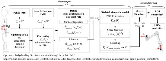
Figure 1.
Overview of the proposed upper extremity motion-based telemanipulation framework.
- Sensor calibration for creating and updating a floating body-fixed frame;
- Forward kinematics of the upper right extremity part;
- Velocity kinematics of the upper extremity part;
- CWR of spatial twist for the scaling adjustment of the upper extremity motion.
2.1. Method for Creating and Updating a Floating Body-Fixed Frame
Figure 2 shows a procedure for creating a body-fixed frame {Bf} through a stand–stoop calibration motion. Since the direction of movements and orientations within the human body can be described with respect to the anatomical reference of the frontal, sagittal, and transverse plane, it is assumed that the initial {Bf} is aligned to the anatomical axes of an anteroposterior, mediolateral, and longitudinal axis. After calculating the difference in orientation between the sensor-fixed frame of the IMU sensors, which are arbitrarily attached to the upper extremity part, and the frame {Bf}, the orientation of the IMU sensor is calibrated to be the same orientation with the frame {Bf}. The detailed {Bf} generation method is described in our previous study [29].
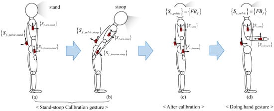
Figure 2.
The procedure of sensor calibration for defining a body-fixed frame {Bf} with stand–stoop motion.
The operator’s body-heading direction is aligned to the longitudinal axis, which is the initially created positive x-axis of {Bf}. The z-axis of {Bf} is always vertically upward with respect to the inertial frame and aligned to the mediolateral axis. Using the orientation of the pelvic IMU, {Bf} is continuously updated so that the operator’s current body-heading direction can be aligned with this x-axis of {Bf}. The following, Equation (1), is a formula for creating the frame {FBf}.
where G denotes the inertial frame, FBf denotes the floating body-fixed frame, and Bf denotes the initial body-fixed frame, which is the initial one of the {FBf}. Sf, pelvic denotes the sensor-fixed frame at the pelvic IMU; Sf, arm and Sf, forearm denotes the sensor-fixed frame at the arm- and forearm-mounted IMUs. Stand and stoop are additionally written in the subscript to indicate the operator’s posture at the time when the orientation of the corresponding sensor is stored. Sc means a calibrated sensor-fixed frame. Then, Equation (2) is used to convert the orientation of the IMU sensors with respect to the inertial frame into orientation with respect to the frame {FBf}. Similarly, the acceleration and angular velocity are expressed with respect to the frame {FBf} through Equations (3) and (4). Here, let us consider a set, , and the subscript i in Equations (2) and (3) holds .
2.2. Forward Kinematics of the Upper Right Extremity Part
In this section, the forward kinematic model, whose screw parameters are represented in Table 2, is derived to calculate the hand’s spatial velocity through the body Jacobian described in Table 3, and Figure 3 illustrates the skeletal kinematic model of the right upper extremity part as a 5R serial open chain composed of two links. It is composed of a 3R right shoulder joint, 2R right elbow joint, and two links (one for serially connecting the shoulder joint and elbow joint and the other for connecting the elbow joint and wrist). In the study, the product of the exponentials (PoE) formula is used to derive the forward kinematics. Thus, let us first choose a fixed stationary frame {FBf} with the origin located at the center of the shoulder joint of the subject and assume the EEF frame {T} is attached to the tip of the second link. Here, we define to be the home pose of {T} when all joint angles are set to zero. As shown in Figure 2d, the upper right extremity is in its home pose right after sensor calibration. The subject is keeping their elbows facing the back and the inside of the forearm facing the walking or heading direction after the attentive posture. Then, the M can be defined as follows,
Table 2.
The values of the screw parameters of the upper right extremity.
Table 3.
The screw parameters of the body form.
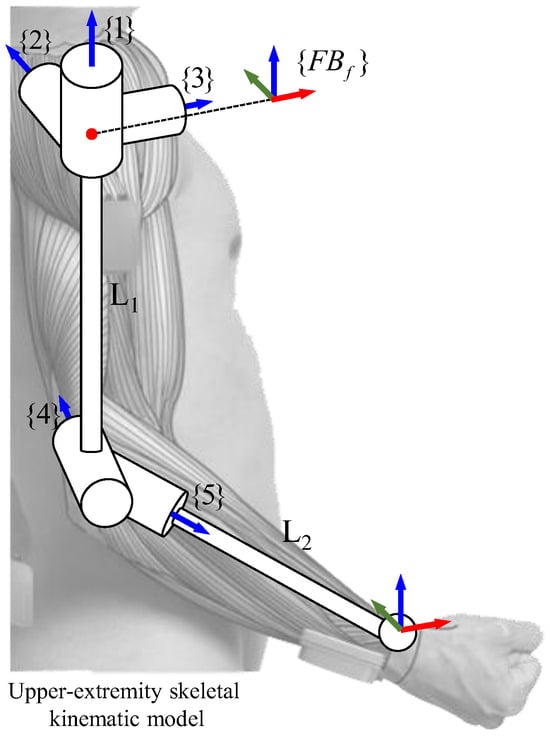
Figure 3.
Joint configuration of the upper extremity skeletal kinematic mode: 3-DOF shoulder joint, 2-DOF elbow joint, and EEF frame at the wrist part.
With the manner of the PoE formula defined in the definitions from 1 to 3, we can write its forward kinematics for arbitrary joint values as a following product of the matrix exponentials in Equation (6), each corresponding to a screw motion.
where the ith joint variable denotes the travel distance along the screw axis because all joints are revolute, can be defined as a unit vector in the positive direction of the ith joint axis, and with any arbitrary point on the ith joint axis, as written with respect to the frame {FBf}.
Definition 1.
Screw axis .
For a given reference frame, a screw axis of a joint can be written as:
where either (i) or (ii) and . If (i) holds, then , where q is a point on the axis of the screw and h is the pitch of the screw (h = 0 for a pure rotation about the screw axis). If (ii) holds, then the pitch of the screw is infinite, and the twist is a translation along the axis defined by . Although we use the pair for both a normalized screw axis (where one of or must be unity) and a general twist (where there are no constraints on and ), the meaning should be apparent from the context [30].
Definition 2.
A matrix representation of the unit screw axis
Definition 3.
Sixth-dimensional exponential coordinates of a homogeneous transformation T.
2.3. Velocity Kinematics of the Upper Extremity Part
In this section, we derived the relationship between the joint rates and spatial twist, in the floating body fixed frame {FBf}. In the case of the upper extremity structure in this study, the EEF frame {T} is located away from the last joint. At this point, it is worth understanding the nature of the PoE formula method in the body form that the body-frame representation of the screw axis for a more distal joint is not affected by the joint displacement at a proximal joint according to Definition 4. Therefore, to obtain the spatial velocity for {FBf} at the origin of the frame {T}, the body Jacobian expressed for {T} should be derived first as in Equation (10). We derive the screw axis of each joint in the frame {FBf}, , first and then transform it to the screw axis of each joint in the frame {T}, , through the following adjoint transformation.
Definition 4.
Space Jacobian .
For a given forward kinematics in Equation (11), the space Jacobian relates the joint rate vector,, to the spatial twist as follows:
where the ith column of is
For i = 2, …, n, with the first column , the body form of the PoE formula is as follows. For a given reference frame, a screw axis of a joint can be written as:
Then, the linear velocity of the origin of the frame {b} with respect to the frame {s} can be obtained from the following Equation (14). It is also worth noting that the spatial velocity in Equation (14) does not mean the linear velocity of the origin of the frame {s}.
where denotes the position of the frame {b}’s origin with respect to the frame {s}.
2.4. Component-Wise Rescaling of Spatial Twist
Equation (15) represents a component-wise rescaling of spatial twist, , to adjust the scale of telemanipulation motion by dividing it into linear and angular motion. Each angular velocity vector and the linear velocity vector , which are the components of the spatial twist, are multiplied by the scaling parameter .
Figure 4 shows the trajectory changes by adjusting the linear and angular scaling parameters. Through (a), you can see that the linear scaling parameter affects the change in position of the trajectory. Also, through (b), we can see that the angle scaling parameter affects the orientation of the trajectory. The respective linear and angular scaling parameters determine the contribution of the linear and angular motions of the upper extremity’s telemanipulation motion to the manipulator’s motion. The rescaled spatial twist will be transmitted to the servo pack of the manipulator via Moveit’s IK instance and ROS controller, as shown in Figure 1. In the next section, we will experimentally explore the effect of scaling parameters in terms of the trajectories’ shape and size of the operator’s upper extremity motion on the manipulator’s motion.
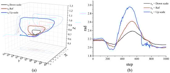
Figure 4.
Effect of linear and angular parameters on trajectory change. (a) Comparison of trajectory positions of the robot end according to linear parameters. (b) Comparison of trajectory orientation of the robot end according to angular parameters.
3. Experiment and Discussion
3.1. Experimental Configurations in Testbench
A testbench, shown in Figure 5, was built to validate the performance of the CWR-based telemanipulation. The details of the testbench and measurement information are as follows.
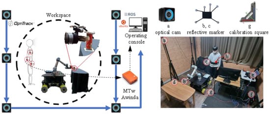
Figure 5.
Testbench composed of (a) six OptiTrack prim 13 motion-capture cameras, (b) reflective markers at the manipulator’s EEF, subject’s hand, and target object, (c) UR5e-based mobile manipulator equipped with 2F-85 Robotiq 2-finger gripper, (d) a target object for teleoperated pick-and-place experiments on the table, (e) a laptop with OptiTrack Motive (Win10) installed, (f) workstation with ROS1 (Ubuntu 20.04) installed, (g) global reference frame of motion-capture cameras, and (h Xsens MTw 3 wearable IMU sensors.
- Testbench: within the testbench, six Prime 13 cameras, three retro-reflective marker sets (on manipulator’s EEF, subject’s hand, and target object), UR5e-based mobile manipulator equipped with 2F-85 Robotiq two-finger gripper, Xsens MTw 3 wearable IMU sensors, a target object for teleoperated pick-and-place experiments on the table, a laptop with OptiTrack Motive (Win 10) installed, and (f) a workstation with ROS 1 (Ubuntu 20.04) installed. The size of the 3D motion-capture stage is 4 m in width, 4 m in height, and 3 m in height. {Of}, the reference frame of the Optitrack prim 13 motion-capture camera, is defined as the exact center point of the floor, which is 2 m wide and 2 m high, and (g) calibration square camera calibration was performed using (CS-200);
- Hand trajectory: wireless IMU sensors are attached to the back of the subject’s pelvis, the arm, and the forearm, which is very close to the wrist part with straps. The reflective marker sets are attached to the wrist and the top of the head to measure the subject’s positions with respect to the frame {Of};
- Motion state: all outputs of the wireless IMU sensor are converted to the output with respect to the frame {FBf}. Note that the conversion relationship between {FBf} and {Of} defined by the calibration square cannot be accurately identified. However, the z-axis is all the same as [0 0 1], and we did our best to align the body-heading direction with the L-square heading direction during the calibration gesture.
3.2. Effects of the CWR of Spatial Twist in Telemanipulation-Based Pick-and-Place
In this section, through the telemanipulation experiment drawing a circle-like trajectory shown in Figure 6, we quantitatively evaluate the effect of the motion-rescaling parameters, in the CWR in terms of the trajectories’ shape and size of the operator’s upper extremity motion to the manipulator’s motion. First, the operator tried to draw the circle with his/her hand, and his/her spatial velocity trajectory calculated from the velocity kinematic model and hand trajectory are also recorded with the IMU sensor measurement and the OptiTrack system, respectively. After recording the operator’s telemanipulation motion, the EEF trajectories with the rescaled operator’s spatial velocity trajectories are recorded according to changing the rescaling parameters without the operator only using the OptiTrack motion-capture system.
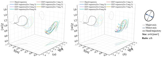
Figure 6.
Experimental results showing the effect of the CWR of a spatial twist on the size and shape of EEF’s trajectories according to the change of (a) magnitude of the scaling parameters and (b) the ratio of linear and angular scaling parameters: (right) definition of the size and ratio of EEF trajectory’s shape.
As shown in Figure 6a, the scaling parameters were set to be the same to find the range of rescaling parameters for the size and shape ratio close to one before exploring the effect of the ratio between linear and angular rescaling parameters. To calculate the size and shape ratio between the operator’s motion and telemanipulated EEF’s motion, it is assumed that the operator’s motion size is normalized to one, and then the size ratio and shape ratio are obtained by changing the scaling parameters, as shown in Table 4. According to the results presented in Table 4 and Figure 6, it was confirmed that the trajectory scale tends to increase as the size of the scaling parameter increases, and the size and shape ratio of 5:5 was the closest to one.
Table 4.
The result of comparing the scale and ratio of EEF trajectories to the operator’s hand trajectory according to the scaling parameter from 1 to 8 with identical linear and angular scaling parameters. Arrows indicate increase or decrease compared to the reference trajectory.
As shown in Figure 6b, we conducted an additional experiment, drawing a circle-like trajectory, the same as in Figure 6a, by changing the ratio between the linear and angular scaling parameters based on five and six. As shown in Table 5, it was confirmed that, as the ratio of angular scale to linear scale increases (to the left of Table 5), the size and shape of the EEF trajectory are distorted compared to the operator trajectory. These results are presumably the result of the difference in manipulability for linear and angular motion in the EEF. As a result of increasing the linear scale ratio to the angular scale (to the right of Table 5), the shape of the EEF trajectory gradually approached the original trajectory, and the size was amplified up to 21.3% and 33.4% at five and six, respectively. It was also confirmed that the smoothest EEF motions were shown in the ratios of 5:2 and 6:3. However, when the size ratio increased too much, the EEF oscillated even with the slightest operator gestures. Therefore, it was decided to conduct the pick-and-place experiment in the next section for six cases of 5:3~5:5 and 6:4~6:6.
Table 5.
The result of comparing scaling and ratio of EEF trajectories to the operator’s motion trajectory according to the changes of the ratio between linear and angular scaling parameters for 5 and 6.
3.3. Effects Validation of the Proposed Dynamic Upper Extremity Motion-Based Telemanipulation through Pick and Place Task
After carrying out pick-and-place experiments for six scaling parameter sets of 5:3~5:5 and 6:4~6:6, we analyze the performances (picking touch violation, pick-and-place boundary violation, and total time) of telemanipulation in terms of the three indices presented in Table 6. This experiment was conducted with six subjects (two females and four males) inexperienced in telemanipulation. After assigning different rescaling conditions, each subject tried the UR5e to pick up objects in the start area and place them in the goal area without any violations, as shown in Figure 7. For each subject, the initial two exercises were performed first, and then the main experiment was performed four times. All experimental processes were video-recorded, and their positions were measured through reflective markers attached to the wrist part, EEF, target object, and operator’s head. In addition, Table 6 presents whether there was unnecessary contact while holding the object, whether the object was placed within the area’s boundary when putting it down, and how long it took.
Table 6.
Experimental results of the teleoperated pick and place in terms of the pick-and-place time, boundary violation, and picking object touch violation for each of the six scaling-parameter ratios (5:5, 5:4, 5:3, 6:6, 6:5, and 6:4).
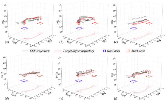
Figure 7.
Comparative experimental results of EEF’s and object’s trajectory in performing the pick place of different subjects for each of the six scaling parameter ratios: (a) 6:6, (b) 6:5, (c) 6:4, (d) 5:5, (e) 5:4, (f) 5:3.
We show the experimental configuration and the trajectory of the shortest mission achievement record for each subject as shown in Figure 8. In the case of the scaling parameter set 5:5~5:3 and 6:6~6:4, it was confirmed that it took an average of 4.18 s and 3.04 s, respectively, except for the case where the total time was the largest in each case. The average pick-and-place time decreased as the linear motion scaling parameter increased. But, in the case of 6:6, picking-touch violations occurred in all trials, and pick-and-place boundary violations occurred in 50% of trials. Meanwhile, even in the case of 5:3, it was confirmed that picking touch violations occurred in 3/4 of the cases. However, considering that the boundary margin of the start and goal areas to the target object diameter was set very tight, the pick and place performed by the proposed method showed good performance. In addition, it is expected to improve further as the operator’s proficiency increases, and it was confirmed that the obstruction of the operator’s vision also affected the occurrence of violations.
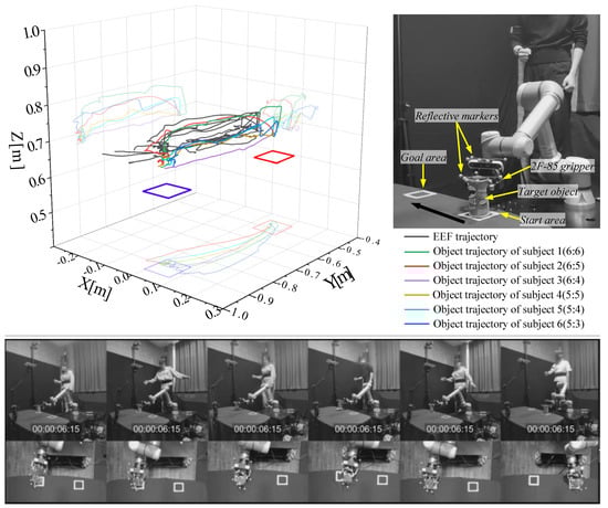
Figure 8.
The best pick-and-place trajectories for each subject in terms of the pick-and-place time, boundary violation, and picking touch violation.
Moreover, to validate the robustness against the body-heading direction change of the operator, which is one of the main contributions of this study, an experiment, as shown in Figure 9, was additionally executed. The operator performs a cross-shaped motion in different body-heading directions, namely, left, front, and right, for the subject in one take. As a result, even performing almost the same motions in different directions, the manipulator’s EEF successfully kept its heading direction with respect to the robot’s base frame {B}. At this point, it should be noted that the slight difference in the robot’s heading direction is an inevitable phenomenon that occurs because the operator cannot perfectly maintain the exact pose of the arm and forearm for the frame {FBf} in this experiment.
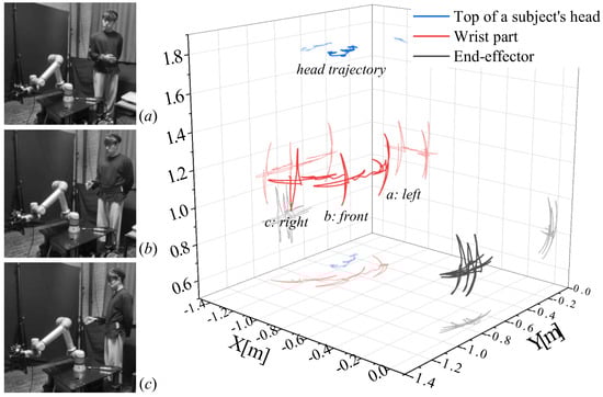
Figure 9.
Experimental validation of the proposed telemanipulation method is robust against the dynamic change of the operator’s body-heading direction by performing a cross-shaped hand motion in different body-heading directions (a–c).
3.4. Discussion of Experiment Results
As shown in Table 6 and Figure 10, when comparing the time taken to complete the pick-and-place task across several experiments for each subject, it was observed that four subjects demonstrated a decrease in the time taken in the final experiment compared to the first. Meanwhile, two subjects showed a slight increase in time, less than 0.1 s. Based on these results, it can be concluded that the subjects’ proficiency in telemanipulation significantly influences the outcomes. Consequently, a key objective is to investigate how this proficiency in telemanipulation affects performance in executing more complex and challenging movements, especially in the context of future implementations of the proposed telemanipulation method.
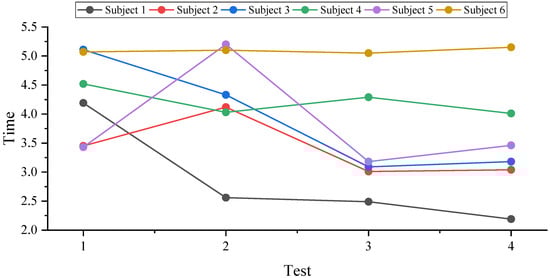
Figure 10.
Record the pick-and-place time required for each subject and the number of experiments.
Additionally, a survey conducted on subjects who either contacted the target object during the picking process or exited the designated area during the placing process indicated control difficulties. These difficulties arose particularly when the manipulator obscured the target object or designated area. Acknowledging this issue, we plan to undertake additional research aimed at resolving this visual obstruction problem. The objective is to enable operators to have a clear view of the worksite from a remote location, which we intend to achieve by soon integrating with the cyber–physical system (CPS) platform.
Although the control method proposed in this study successfully performed real-time omnidirectional control of a 6-DOF manipulator in a real environment, there are still some limitations that have not been resolved. First, drift occurs due to bias-error accumulation, which is a traditional problem with IMU sensors. The telemanipulation method proposed in this study controls the pose of the manipulator EEF based on the spatial velocity of the upper extremity of the human body. Therefore, it is less affected by bias-error accumulation compared to kinematic model-based position-control methods that map joint data between robots and humans. However, because IMU orientation data is used in the spatial velocity calculation process, it is not completely unaffected by sensor bias error. Therefore, when used for a long time, control performance decreases and a midprocess recalibration process is required. The following are problems caused by differences in the joint configuration and degrees of freedom of the actual subject’s right upper limb of the human body and the kinematic model of the human right upper limb used in the study. The telemanipulation method proposed in this study controls the manipulator EEF based on spatial velocity, so there is no difficulty in omnidirectional control. However, due to the difference in degrees of freedom between the two models, it is impossible to implement movements that precisely resemble the extremities of the subject’s human upper limbs, and the subject may feel unnatural during the control movement process. Therefore, in future research, there is a need for a real-time omnidirectional telemanipulation method based on a kinematic model complemented by an increase in the number of DOFs and similarity in joint configuration.
4. Conclusions
This study introduces a framework to improve upper extremity motion-based tele-manipulation by component-wise rescaling (CWR) of spatial twist. This method allows for separate adjustments of the linear and angular scaling parameters, significantly improving precision and dexterity. Through testbench experiments, the significant range of rescaling parameters has been successfully identified in terms of the size and shape ratio of EEF’s trajectory to the operator’s hand trajectory. The effect of ratio change between the linear and angular scaling parameters has been explored regarding the controllability and manipulability of telemanipulation. First, the linear and angular parameters were changed so that the trajectory of the robot EEF could be output like the trajectory of the distal end of the subject’s upper limb. At first, the linear and angular parameters were set to the same value and then changed, and trajectories with similar shapes and sizes were output for parameters 5 and 6. Afterward, the trajectory was analyzed by changing the linear and angular parameters at different rates based on parameters 5 and 6. As a result, we determined six optimal parameters with similar shapes and trajectories. To evaluate the operating performance of the proposed telemanipulation method, we conducted a pick-and-place experiment with six subjects with no control experience in different physical conditions. All six subjects successfully performed the pick-and-place experiment, and it was confirmed that the experiment time shortened as the number of experiments increased. Through this, we were able to confirm that the subject’s operating experience affects control performance. In addition, it was confirmed that visual feedback through the subject’s naked eyes was limited due to unintentional contact with the target object, and the need for future visual feedback research that shares the view of the robot EEF through CPS was suggested.
Finally, this study makes the following research contributions. Through experiments in testbench, with the CWR of the spatial twist from the parameter-invariant skeletal kinematic model, it was confirmed that all the subjects could successfully perform the pick and place of an object into a very narrow area with tight margins regardless of the operator’s proficiency and different human factors.
From the perspective of intuitiveness and motion similarity in telemanipulation, we believe that the desirable motion rescaling should have a wide range of controllable size ratios while maintaining a shape ratio close to one. Thus, as future works to this study, we will focus on developing a method to independently adjust the size ratio while maintaining the size ratio.
Author Contributions
Conceptualization, D.L.; methodology, D.L.; software, D.N., H.C., H.J. and D.L.; validation, D.N., H.C., H.J., J.K, T.K. and D.L.; formal analysis, D.N., H.C., H.J., J.K, T.K. and D.L.; investigation, D.L.; resources, D.L.; data curation, D.N. and H.C.; writing—original draft preparation, D.N. and D.L.; writing—review and editing, D.N. and D.L.; visualization, D.N., H.C., H.J., J.K, T.K. and D.L.; supervision, D.L.; project administration, D.L.; funding acquisition, D.L. All authors have read and agreed to the published version of the manuscript.
Funding
This research was supported by the Basic Science Research Program through the National Research Foundation of Korea (NRF) funded by the Ministry of Education (NRF-2023 R1F1A1074704); Institute of Information and Communications Technology Planning and Evaluation (IITP) grant funded by the Korea government (MSIT) (No. 2023-0-00218); the MSIT (Ministry of Science and ICT), Korea, under the Innovative Human Resource Development for Local Intellectualization support program (IITP-2023-RS-2022-00156360) supervised by the IITP (Institute for Information and Communications Technology Planning and Evaluation); Korea Institute for Advancement of Technology (KIAT) grant funded by the Korea Government (MOTIE) (P0017123, HRD Program for Industrial Innovation).
Institutional Review Board Statement
Not applicable.
Informed Consent Statement
Not applicable.
Data Availability Statement
The data used to support the findings of this study are available from the corresponding author upon request.
Conflicts of Interest
The authors declare no conflicts of interest.
Nomenclature
| CWR | Component-wise rescaling |
| EEF | End effector |
| FOV | Field of view |
| CNN | Convolutional neural network |
| EMG | Electromyography |
| sEMG | Surface electromyography |
| IMU | Inertial measurement unit |
| DOF | Degrees of Freedom |
| ML | Machine learning |
| PoE | Product of exponentials |
| ROS | Robot operating system |
| CPS | Cyber–physical system |
| Rotation matrix | |
| Global reference frame | |
| Sensor-fixed frame at initial standing posture | |
| Sensor-fixed frame at initial stooping posture | |
| Body-fixed frame | |
| Floating body-fixed frame | |
| Sensor-fixed frame | |
| Sensor-calibrated frame | |
| End-effector frame of upper extremity | |
| Manipulator base frame | |
| Optical camera reference frame | |
| Acceleration | |
| Angular rate | |
| Three-dimensional special orthogonal group | |
| Three-dimensional special Euclidean group | |
| Rescaling parameter (linear and angular velocity) |
References
- Kumar, N.; Lee, S.C. Human-machine interface in smart factory: A systematic literature review. Technol. Forecast. Soc. Change 2022, 174, 121284. [Google Scholar] [CrossRef]
- Pajor, M.; Miądlicki, K.; Saków, M. Kinect sensor implementation in FA-NUC robot manipulation. Arch. Mech. Technol. Autom. 2014, 34, 35–44. [Google Scholar]
- Mazhar, O.; Navarro, B.; Ramdani, S.; Passama, R.; Cherubini, A. A real-time human-robot interaction framework with robust background invariant hand gesture de-tection. Robot. Comput. Integr. Manuf. 2019, 60, 34–48. [Google Scholar] [CrossRef]
- Zhou, D.; Shi, M.; Chao, F.; Lin, C.M.; Yang, L.; Shang, C.; Zhou, C. Use of human gestures for controlling a mobile robot via adaptive cmac network and fuzzy logic controller. Neurocomputing 2018, 282, 218–231. [Google Scholar] [CrossRef]
- Moe, S.; Schjolberg, I. Real-Time Hand Guiding of Industrial Manipulator in 5 DOF Using Microsoft Kinect and Accelerometer. In Proceedings of the 2013 IEEE International Symposium on Robot and Human Interactive Communication (RO-MAN), Gyeongju, Republic of Korea, 26–29 August 2013; pp. 644–649. [Google Scholar]
- Lopes, M.; Melo, A.S.C.; Cunha, B.; Sousa, A.S.P. Smartphone-Based Video Analysis for Guiding Shoulder Therapeutic Exercises: Concurrent Validity for Movement Quality Control. Appl. Sci. 2023, 13, 12282. [Google Scholar] [CrossRef]
- Latreche, A.; Kelaiaia, R.; Chemori, A.; Kerboua, A. A New Home-Based Upper-and Lower-Limb Telerehabilitation Platform with Experimental Valida-tion. Arab. J. Sci. Eng. 2023, 48, 1–16. [Google Scholar] [CrossRef] [PubMed]
- Vogel, J.; Castellini, C.; van der Smagt, P. EMG-Based Teleoperation and Manipulation with the DLR LWR-III. In Proceedings of the 2011 IEEE/RSJ International Conference on Intelligent Robots and Systems, San Francisco, CA, USA, 25–30 September 2011. [Google Scholar]
- Wolf, M.T.; Assad, C.; Stoica, A.; You, K.; Jethani, H.; Vernacchia, M.T.; Fromm, J.; Iwashita, Y. Decoding Static and Dynamic Arm and Hand Gestures from the JPL BioSleeve. In Proceedings of the 2013 IEEE Aerospace Conference, Big Sky, MT, USA, 2–9 March 2013; pp. 1–9. [Google Scholar]
- Hiroaki, G.; Osu, R. Task-dependent viscoelasticity of human multi joint arm and its spatial characteristics for interaction with environments. J. Neurosci. 1998, 18, 8965–8978. [Google Scholar]
- Zhang, Y.; Huang, Y.; Sun, X.; Zhao, Y.; Guo, X.; Liu, P.; Zhang, Y. Static and dynamic human arm/hand gesture capturing and recognition via multi-information fu-sion of flexible strain sensors. IEEE Sens. J. 2020, 20, 6450–6459. [Google Scholar] [CrossRef]
- Kulkarni, P.V.; Illing, B.; Gaspers, B.; Brüggemann, B.; Schulz, D. Mobile manipulator control through gesture recognition using IMUs and Online Lazy Neighborhood Graph search. Acta IMEKO 2019, 8, 3–8. [Google Scholar] [CrossRef]
- Choi, H.; Jeon, H.; Noh, D.; Kim, T.; Lee, D. Hand-guiding gesture-based telemanipulation with the gesture mode classification and state estima-tion using wearable IMU sensors. Mathematics 2023, 11, 3514. [Google Scholar] [CrossRef]
- Škulj, G.; Vrabič, R.; Podržaj, P. A Wearable IMU System for Flexible Teleoperation of a Collaborative Industrial Robot. Sensors 2021, 21, 5871. [Google Scholar] [CrossRef]
- Vargas-Valencia, L.S.; Elias, A.; Rocon, E.; Bastos-Filho, T.; Frizera, A. An IMU-to-Body Alignment Method Applied to Human Gait Analysis. Sensors 2016, 16, 2090. [Google Scholar] [CrossRef]
- Bertomeu-Motos, A.; Lledó, L.D.; Díez, J.A.; Catalan, J.M.; Ezquerro, S.; Badesa, F.J.; Garcia-Aracil, N. Estimation of Human Arm Joints Using Two Wireless Sensors in Robotic Rehabilitation Tasks. Sensors 2015, 15, 30571–30583. [Google Scholar] [CrossRef]
- Tian, Y.; Meng, X.; Tao, D.; Liu, D.; Feng, C. Upper limb motion tracking with the integration of IMU and Kinect. Neurocomputing 2015, 159, 207–218. [Google Scholar] [CrossRef]
- Lin, C.-J.; Peng, H.-Y. A Study of the Human-Robot Synchronous Control Based on IMU and EMG Sensing of an Upper Limb. In Proceedings of the 2022 13th Asian Control Conference (ASCC), Jeju, Republic of Korea, 4–7 May 2022; pp. 1474–1479. [Google Scholar]
- Carrino, S.; Mugellini, E.; Khaled, O.A.; Ingold, R. Gesture-Based Hybrid Approach for HCI in Ambient Intelligent Environmments. In Proceedings of the 2011 IEEE International Conference on Fuzzy Systems (FUZZ-IEEE 2011), Taipei, Taiwan, 27–30 June 2011; pp. 86–93. [Google Scholar]
- Chen, P.-J.; Du, Y.-C.; Shih, C.-B.; Yang, L.-C.; Lin, H.-T.; Fan, S.-C. Development of an Upper Limb Rehabilitation System Using Inertial Movement Units and Kinect Device. In Proceedings of the 2016 International Conference on Advanced Materials for Science and Engineering (ICAMSE), Tainan, Taiwan, 12–13 November 2016; Institute of Electrical and Electronics Engineers (IEEE): New York, NY, USA, 2016; pp. 275–278. [Google Scholar]
- Zhou, S.; Fei, F.; Zhang, G.; Mai, J.D.; Liu, Y.; Liou, J.Y.J.; Li, W.J. 2D Human Gesture Tracking and Recognition by the Fusion of MEMS Inertial and Vision Sensors. IEEE Sensors J. 2013, 14, 1160–1170. [Google Scholar] [CrossRef]
- Yoo, M.; Na, Y.; Song, H.; Kim, G.; Yun, J.; Kim, S.; Moon, C.; Jo, K. Motion Estimation and Hand Gesture Recognition-Based Human–UAV Interaction Approach in Real Time. Sensors 2022, 22, 2513. [Google Scholar] [CrossRef]
- Moradi, M.; Dang, S.; Alsalem, Z.; Desai, J.; Palacios, A. Integrating Human Hand Gestures with Vision Based Feedback Controller to Navigate a Virtual Robotic Arm. In Proceedings of the 2020 23rd International Symposium on Measurement and Control in Robotics (ISMCR), Budapest, Hungary, 15–17 October 2020; pp. 1–6. [Google Scholar]
- Zhou, H.; Alici, G. Non-Invasive Human-Machine Interface (HMI) Systems with Hybrid On-Body Sensors for Controlling Upper-Limb Prosthesis: A Review. IEEE Sens. J. 2022, 22, 10292–10307. [Google Scholar] [CrossRef]
- Alfaro, J.G.C.; Trejos, A.L. User-Independent Hand Gesture Recognition Classification Models Using Sensor Fusion. Sensors 2022, 22, 1321. [Google Scholar] [CrossRef]
- Shahzad, W.; Ayaz, Y.; Khan, M.J.; Naseer, N.; Khan, M. Enhanced Performance for Multi-Forearm Movement Decoding Using Hybrid IMU–sEMG Interface. Front. Neurorobotics 2019, 13, 43. [Google Scholar] [CrossRef] [PubMed]
- Amini, S.; Dehkordi, S.F.; Fahraji, S.H. Motion Equation Derivation and Tip-Over Evaluations for K Mobile Manipulators with the Consideration of Motors mass By the Use of Gibbs-Appell Formulation. In Proceedings of the 5th RSI International Conference on Robotics and Mechatronics (IcRoM), Tehran, Iran, 25–27 October 2017; pp. 502–507. [Google Scholar] [CrossRef]
- Tanha, S.D.N.; Dehkordi, S.F.; Korayem, A.H. Control a Mobile Robot in Social Environments by Considering Human as a Moving Obstacle. In Proceedings of the 2018 6th RSI International Conference on Robotics and Mechatronics (IcRoM), Tehran, Iran, 23–25 October 2018; pp. 256–260. [Google Scholar]
- Jeon, H.; Kim, S.L.; Kim, S.; Lee, D. Fast wearable sensor–based foot–ground contact phase classification using a convolutional neural network with sliding-window label overlapping. Sensors 2020, 20, 4996. [Google Scholar] [CrossRef]
- Lynch, K.M.; Park, F.C. Modern Robotics; Cambridge University Press: Cambridge, MA, USA, 2017. [Google Scholar]
Disclaimer/Publisher’s Note: The statements, opinions and data contained in all publications are solely those of the individual author(s) and contributor(s) and not of MDPI and/or the editor(s). MDPI and/or the editor(s) disclaim responsibility for any injury to people or property resulting from any ideas, methods, instructions or products referred to in the content. |
© 2024 by the authors. Licensee MDPI, Basel, Switzerland. This article is an open access article distributed under the terms and conditions of the Creative Commons Attribution (CC BY) license (https://creativecommons.org/licenses/by/4.0/).