


Explicit Identification of Pointwise Terrain Gradients for Speed Compensation of Four Driving Tracks in Passively Articulated Tracked Mobile Robot

Abstract
:1. Introduction
- The suspension kinematics-based speed compensation methods are newly proposed to successfully calculate the track-terrain contact angles (TTCA) at any arbitrary rough terrains without a pointwise terrain elevation map.
- Then, the uncertainties in the kinematic parameters of MR kinematics and the relative orientation of the driving track can be successfully removed.
- The proposed algorithm is evaluated through simulation and experimental results, demonstrating improved trajectory tracking performance compared to traditional control methods.
- Additionally, the paper includes an analysis of the robustness and stability of the proposed algorithm under different operating conditions.
- Overall, this research aims to contribute to the advancement of tracked mobile robot technology and its potential applications in various fields.
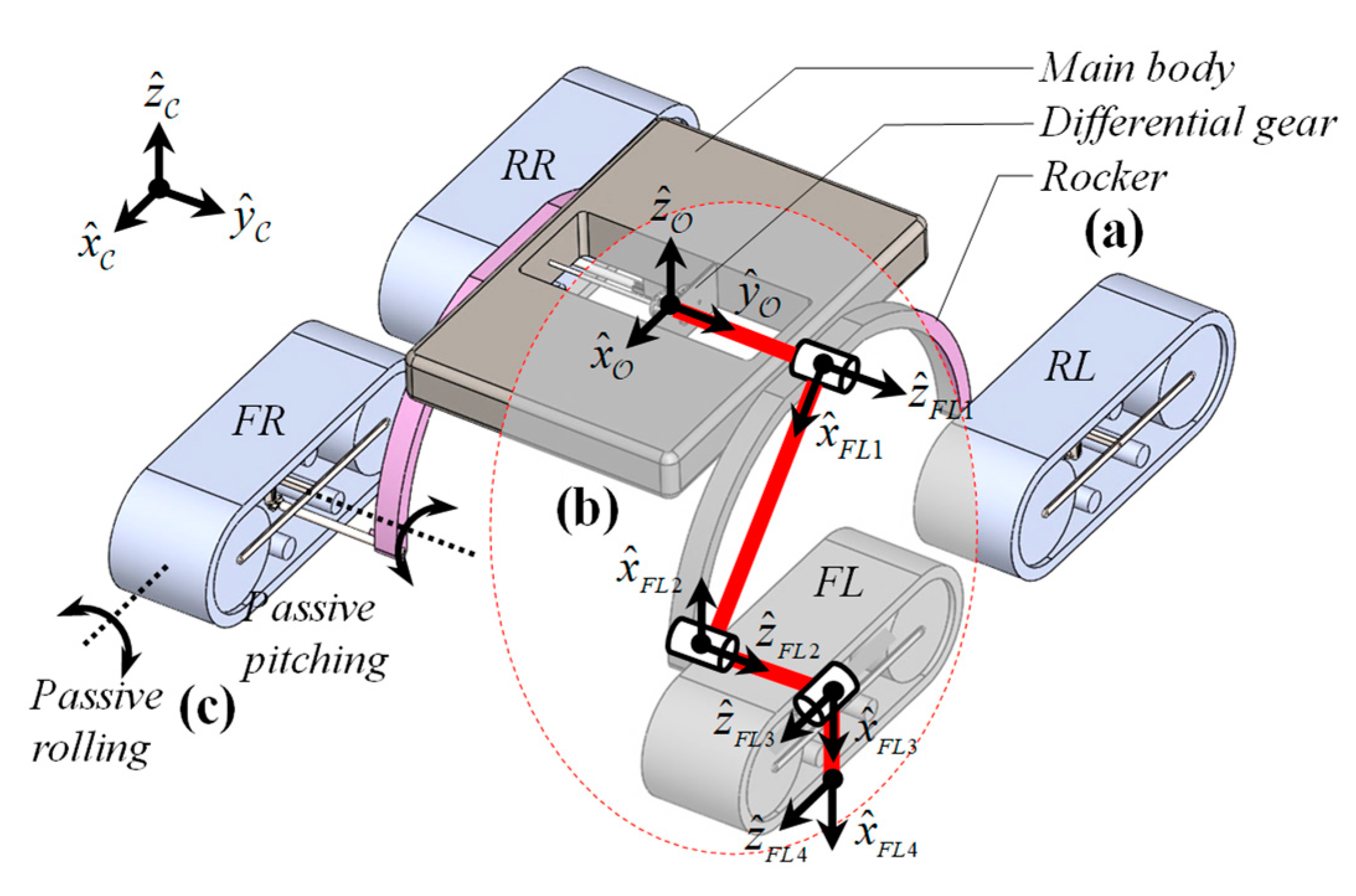
2. A New Quad-Tracked Mobile Robot with Passively Articulated Suspensions
3. MR Kinematics for Rough Terrains
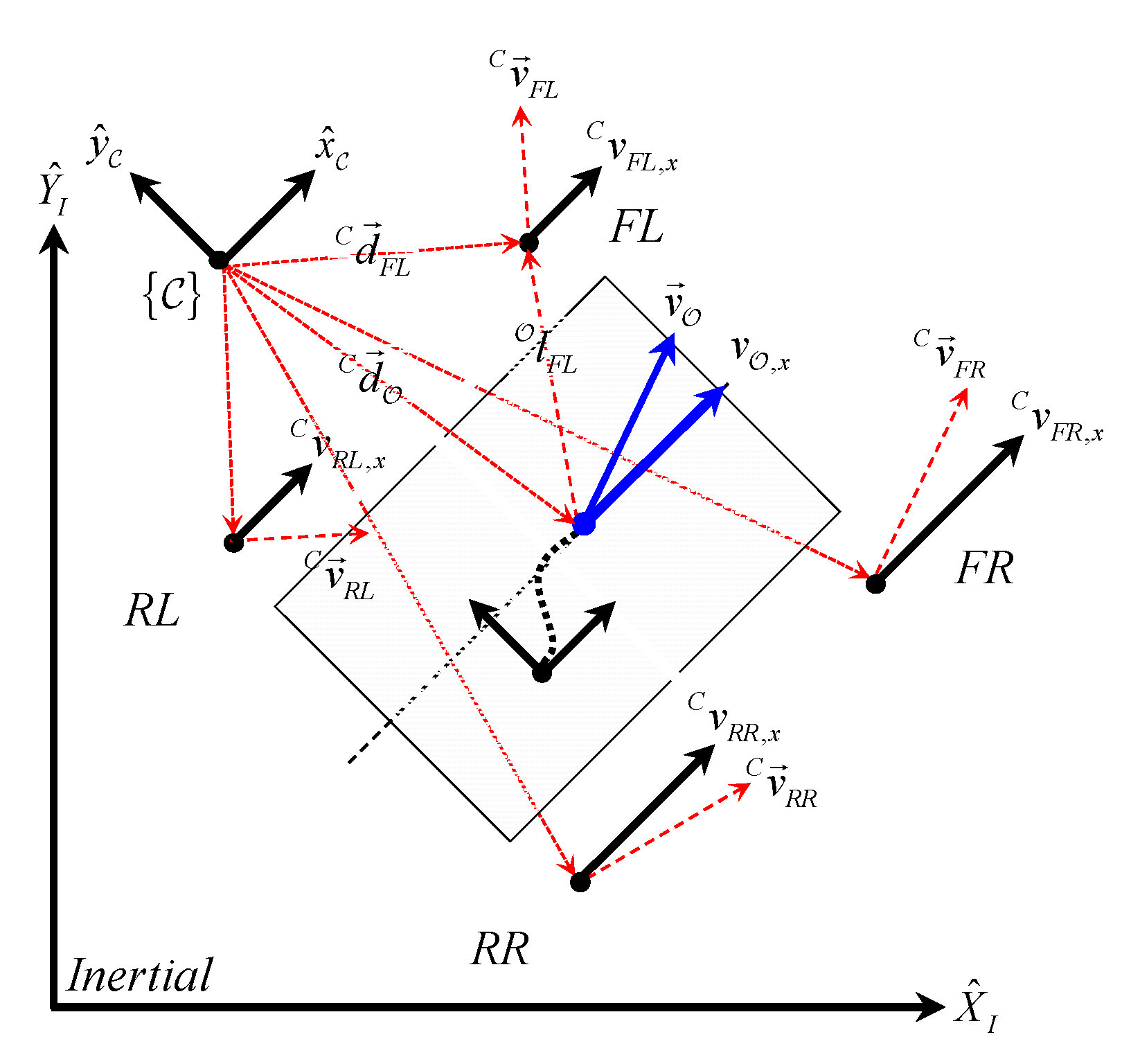
3.1. Planar SSMR Kinematics
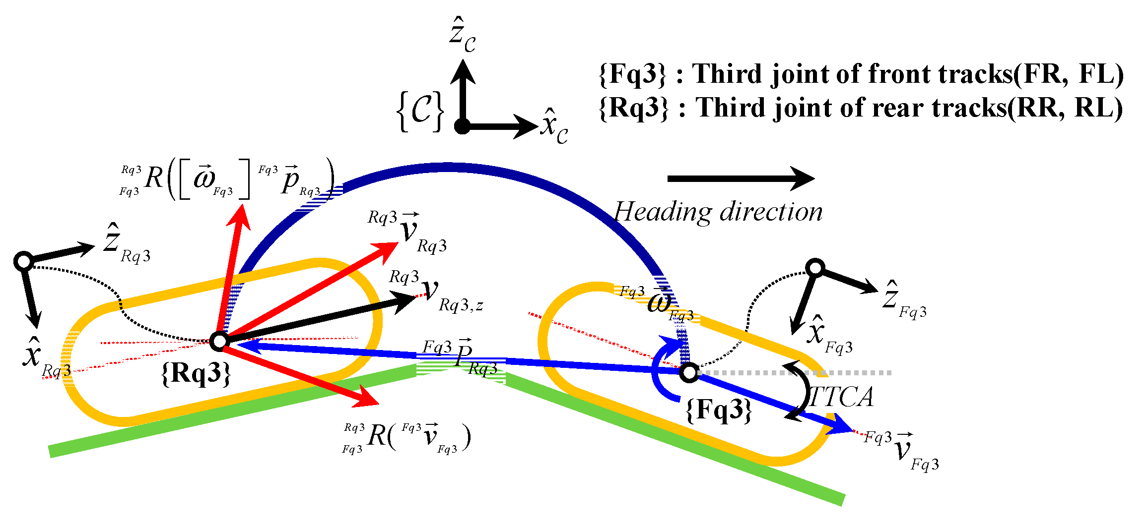
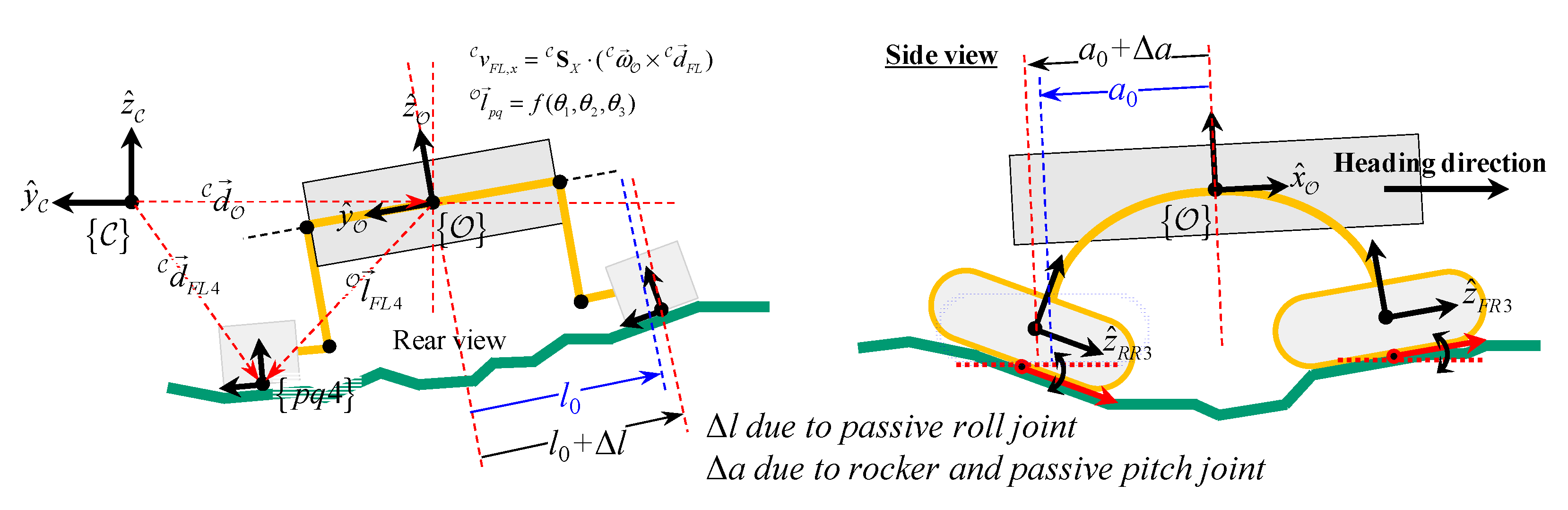
3.2. Suspension Kinematics
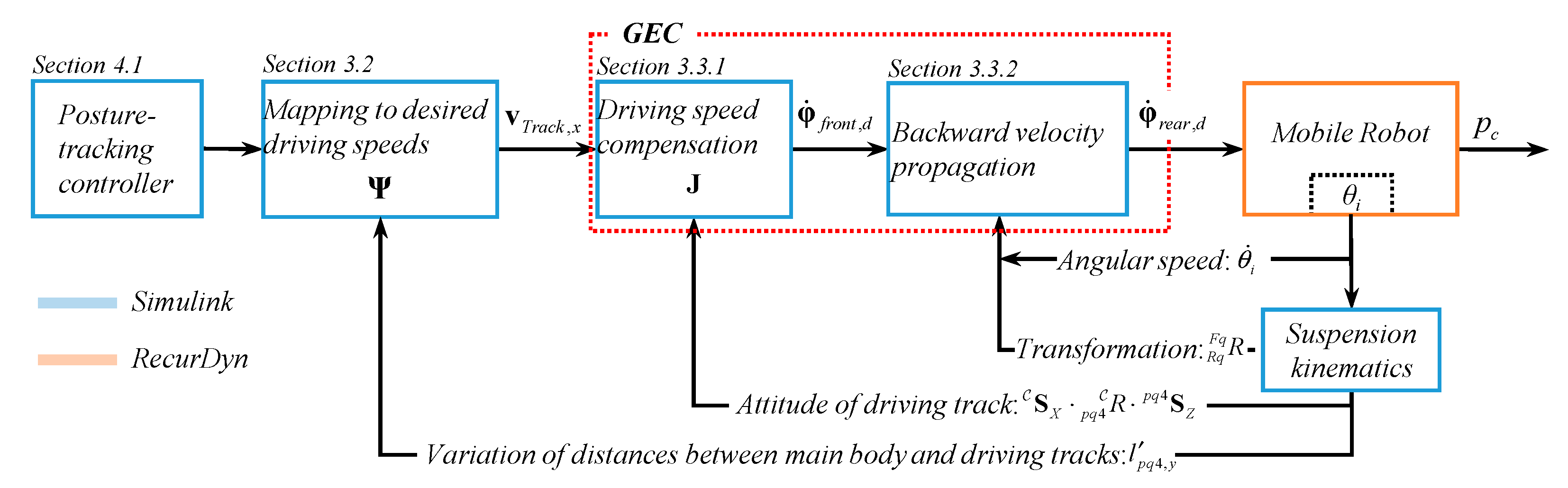
3.3. GEC Based Terrain Gradient Identification and Backward Velocity Propagation
3.3.1. Driving Speed Compensation
3.3.2. Backward Velocity Propagation for Preventing Undesired Track Pitching
4. Verification of the Single GEC and Backward Velocity Propagation Combined GEC
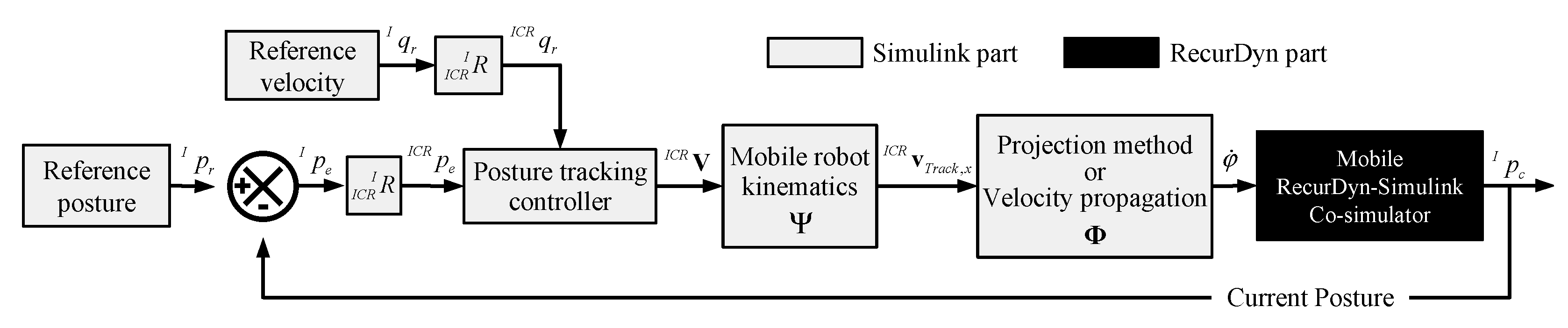
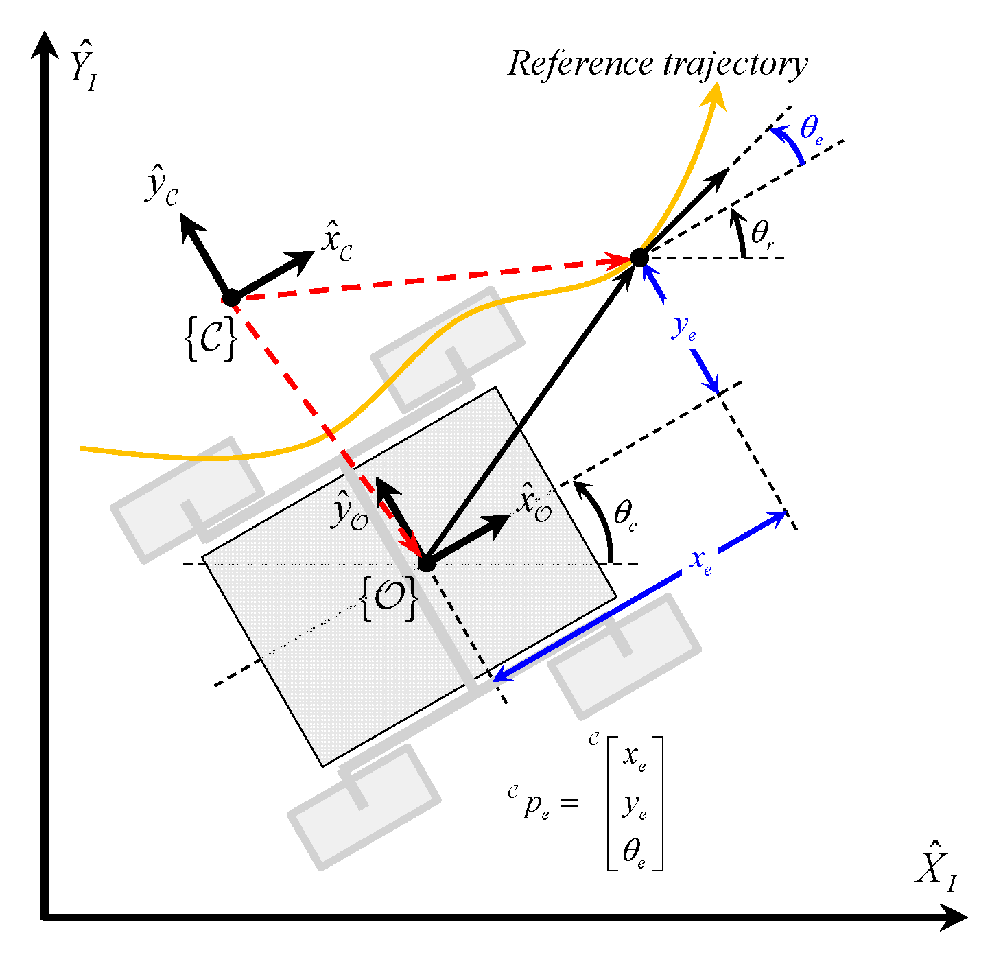
4.1. Posture Tracking Controller
4.2. Simulation
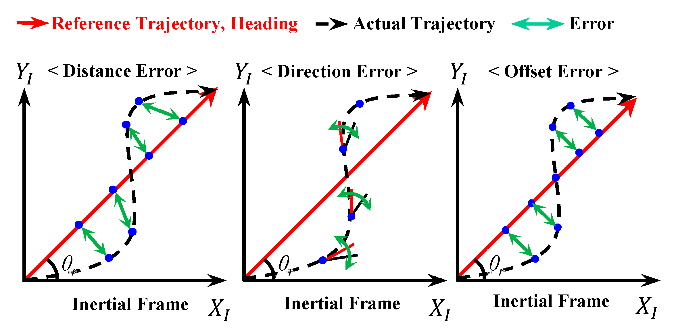
4.3. Performance Indices
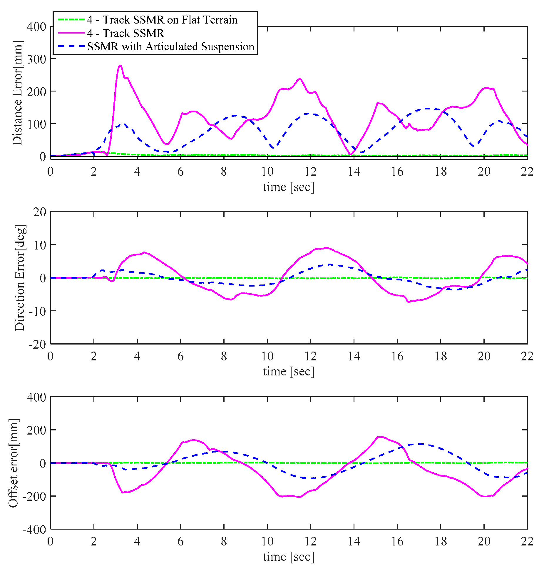
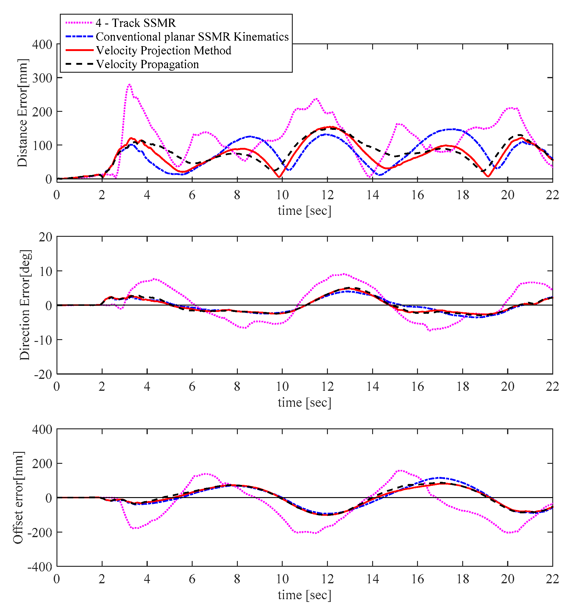
4.4. Simulation Results
- No suspension + planar SSMR kinematics;
- Suspension + planar SSMR kinematics;
- Suspension + GEC w/o backward propagation;
- Suspension + GEC w/backward propagation.
5. Discussion and Conclusions
Author Contributions
Funding
Informed Consent Statement
Data Availability Statement
Conflicts of Interest
References
- Lindemann, R.; Reid, L.; Voorhees, C. Mobility Sub-System for the Exploration Technology Rover. 1999. Available online: https://trs.jpl.nasa.gov/bitstream/handle/2014/17115/99-0537.pdf?sequence=1 (accessed on 8 January 2022).
- NASA, Mars Rover Curiosity. 2015. Available online: http://www.nasa.gov/mission_pages/msl/index.html/ (accessed on 15 June 2022).
- Lee, D.; Lee, S.; Ku, N.; Lim, C.; Lee, K.-Y.; Kim, T.-W.; Kim, J.; Kim, S.H. Development of a mobile robotic system for working in the double-hulled structure of a ship. Robot. Comput. Integr. Manuf. 2010, 26, 13–23. [Google Scholar] [CrossRef]
- Kim, H.; Kim, D.; Yang, H.; Lee, K.; Seo, K.; Chang, D.; Kim, J. Development of a wall-climbing robot using a tracked wheel mechanism. J. Mech. Sci. Technol. 2008, 22, 1490–1498. [Google Scholar] [CrossRef]
- Raibert, M.; Blankespoor, K.; Nelson, G.; Playter, R. Bigdog, the rough-terrain quadruped robot. IFAC Proc. Vol. 2008, 41, 10822–10825. [Google Scholar] [CrossRef]
- Ma, J.; Susca, S.; Bajracharya, M.; Matthies, L.; Malchano, M.; Wooden, D. Robust multi-sensor, day/night 6-DOF pose estimation for a dynamic legged vehicle in GPS-denied environments. In Proceedings of the 2012 IEEE International Conference on Robotics and Automation, Saint Paul, MN, USA, 14–18 May 2012; pp. 619–626. [Google Scholar]
- Yamauchi, B.M. PackBot: A versatile platform for military robotics. In Proceedings of the Unmanned Ground Vehicle Technology VI, Bellingham, WA, USA, 13–15 April 2004; pp. 228–237. [Google Scholar]
- Lee, W.; Kang, S.; Kim, M.; Park, M. ROBHAZ-DT3: Teleoperated mobile platform with passively adaptive double-track for hazardous environment applications. In Proceedings of the 2004 IEEE/RSJ International Conference on Intelligent Robots and Systems (IROS) (IEEE Cat. No. 04CH37566), Sendai, Japan, 28 September–2 October 2004; pp. 33–38. [Google Scholar]
- Zhang, D.; Gao, Z. Hybrid head mechanism of the groundhog-like mine rescue robot. Robot. Comput.-Integr. Manuf. 2011, 27, 460–470. [Google Scholar] [CrossRef]
- DARPA. DARPA Robotics Challenge Program: 2012 to 2015. Available online: https://www.youtube.com/watch?v=mpsXQCHrAlM/ (accessed on 25 September 2015).
- DARPA. DARPA Robotics Challenge 2015 Finals. Available online: https://www.youtube.com/watch?v=dv9Wm20UrcU/ (accessed on 6 October 2015).
- Siegwart, R.; Lamon, P.; Estier, T.; Lauria, M.; Piguet, R. Innovative design for wheeled locomotion in rough terrain. Robot. Auton. Syst. 2002, 40, 151–162. [Google Scholar] [CrossRef]
- Thueer, T.; Krebs, A.; Siegwart, R. Comprehensive locomotion performance evaluation of all-terrain robots. In Proceedings of the 2006 IEEE/RSJ International Conference on Intelligent Robots and Systems, Beijing, China, 9–15 October 2006; pp. 4260–4265. [Google Scholar]
- Caracciolo, L.; De Luca, A.; Iannitti, S. Trajectory tracking control of a four-wheel differentially driven mobile robot. In Proceedings of the 1999 IEEE International Conference on Robotics and Automation (Cat. No. 99CH36288C), Detroit, MI, USA, 10–15 May 1999; pp. 2632–2638. [Google Scholar]
- Kozłowski, K.; Pazderski, D. Modeling and control of a 4-wheel skid-steering mobile robot. Int. J. Appl. Math. Comput. Sci. 2004, 14, 477–496. [Google Scholar]
- Shuang, G.; Cheung, N.C.; Cheng, K.E.; Lei, D.; Xiaozhong, L. Skid steering in 4-wheel-drive electric vehicle. In Proceedings of the 2007 7th International Conference on Power Electronics and Drive Systems, Bangkok, Thailand, 27–30 November 2007; pp. 1548–1553. [Google Scholar]
- Tarokh, M.; McDermott, G.J. Kinematics modeling and analyses of articulated rovers. IEEE Trans. Robot. 2005, 21, 539–553. [Google Scholar] [CrossRef]
- Kim, J.; Jeong, H.; Lee, D. Performance optimization of a passively articulated mobile robot by minimizing maximum required friction coefficient on rough terrain driving. Mech. Mach. Theory 2021, 164, 104368. [Google Scholar] [CrossRef]
- Jeong, H.; Yu, J.; Lee, D. Track HM Design for Dynamic Analysis of 4-tracked Vehicle on Rough Terrain Using Recurd. Trans. Korean Soc. Mech. Eng. A 2021, 45, 275–283. [Google Scholar] [CrossRef]
- Kanayama, Y.; Kimura, Y.; Miyazaki, F.; Noguchi, T. A stable tracking control method for an autonomous mobile robot. In Proceedings of the 1990 IEEE International Conference on Robotics and Automation, Cincinnati, OH, USA, 13–18 May 1990; pp. 384–389. [Google Scholar]
- Apostolopoulos, D.S. Analytical Configuration of Wheeled Robotic Locomotion; Carnegie Mellon University: Pittsburgh, PA, USA, 2001. [Google Scholar]
- Haji, T.; Kinugasa, T.; Yoshida, K.; Amano, H.; Osuka, K. Maneuverability of flexible mono-tread mobile track (FMT). In Proceedings of the 2009 ICCAS-SICE, Fukuoka, Japan, 18–21 August 2009; pp. 3427–3432. [Google Scholar]
- Michaud, S.; Richter, L.; Thueer, T.; Gibbesch, A.; Huelsing, T.; Schmitz, N.; Weiss, S.; Krebs, A.; Patel, N.; Joudrier, L. Rover chassis evaluation and design optimisation using the RCET. In Proceedings of the ASTRA, 9th ESA Workshop on Advanced Space Technologies for Robotic and Automation, Noordwijk, The Netherlands, 28–30 November 2006. [Google Scholar]
- Zhang, P.; Deng, Z.; Hu, M.; Gao, H. Mobility performance analysis of lunar rover based on terramechanics. In Proceedings of the 2008 IEEE/ASME International Conference on Advanced Intelligent Mechatronics, Xi’an, China, 2–5 July 2008; pp. 120–125. [Google Scholar]
- Ding, L.; Gao, H.; Deng, Z.; Song, P.; Liu, R. Design of comprehensive high-fidelity/high-speed virtual simulation system for lunar rover. In Proceedings of the 2008 IEEE Conference on Robotics, Automation and Mechatronics, Chengdu, China, 21–24 September 2008; pp. 1118–1123. [Google Scholar]
- Thueer, T.; Siegwart, R. Mobility evaluation of wheeled all-terrain robots. Robot. Auton. Syst. 2010, 58, 508–519. [Google Scholar] [CrossRef]
- Deng, Z.; Fan, X.; Gao, H.; Ding, L. Influence analysis of terramechanics on conceptual design of manned lunar rover’s locomotion system. In Proceedings of the 2011 International Conference on Electronic & Mechanical Engineering and Information Technology, Heilongjiang, China, 12–14 August 2011; pp. 645–648. [Google Scholar]
- Gupta, A.K.; Gupta, V.K. Design and development of six-wheeled Multi-Terrain Robot. In Proceedings of the 2013 International Conference on Control, Automation, Robotics and Embedded Systems (CARE), Jabalpur, India, 16–18 December 2013; pp. 1–6. [Google Scholar]
- Michaluk, N. Design Methods for Cost-Effective Teams of Mobile Robots in Uncertain Terrain; Massachusetts Institute of Technology: Cambridge, MA, USA, 2014. [Google Scholar]
- Paez, L.; Melo, K. A preliminary review on metrics for modular snake robots locomotion. In Proceedings of the 4th Annual IEEE International Conference on Cyber Technology in Automation, Control and Intelligent, Hong Kong, China, 4–7 June 2014; pp. 539–545. [Google Scholar]


| i | ωi | vFL,i | vFR,i | vRR,i | vRL,i |
|---|---|---|---|---|---|
| 1 | (0, 1, 0) | (0, l1, 0) | (0, −l1, 0) | (0, −l1, 0) | (0, l1, 0) |
| 2 | (0, 1, 0) | (l2·cθs, l1, −l2·sθs) | (l2·cθs, −l1, −l2·sθs) | (−l2·cθs, −l1, −l2·sθs) | (−l2·cθs, l1, −l2·sθs) |
| 3 | (1, 0, 0) | (l2·cθs, l1 + l3, −l2·sθs) | (l2·cθs, −l1 − l3, −l2·sθs) | (−l2·cθs, −l1 − l3, −l2·sθs) | (−l2·cθs, l1 + l3, −l2·sθs) |
| 4 | (1, 0, 0) | (l2·cθs, l1 + l3, −l2·sθs − l4) | (l2·cθs, −l1 − l3, −l2·sθs − l4) | (−l2·cθs, −l1 − l3, −l2·sθs − l4) | (−l2·cθs, l1 + l3, −l2·sθs − l4) |
| Symbol | Unit | Value | |
|---|---|---|---|
| Total mass | kg | 1400.7 | |
| Main body mass | kg | 512.8 | |
| Track mass | kg | 470 | |
| Center of Mass | COM, x | mm | 0.03 |
| COM, y | −0.12 | ||
| COM, z | −236.80 | ||
| Total height | H1 | mm | 612 |
| Total width | W1 | mm | 1670 |
| Total length | L | mm | 1760 |
| Wheelbase | W2 | mm | 1377 |
| Track diameter | D | mm | 267.6 |
| Track height | H2 | mm | 314.5 |
| Track width | W3 | mm | 291 |
| Roll joint height | H3 | mm | 90 |
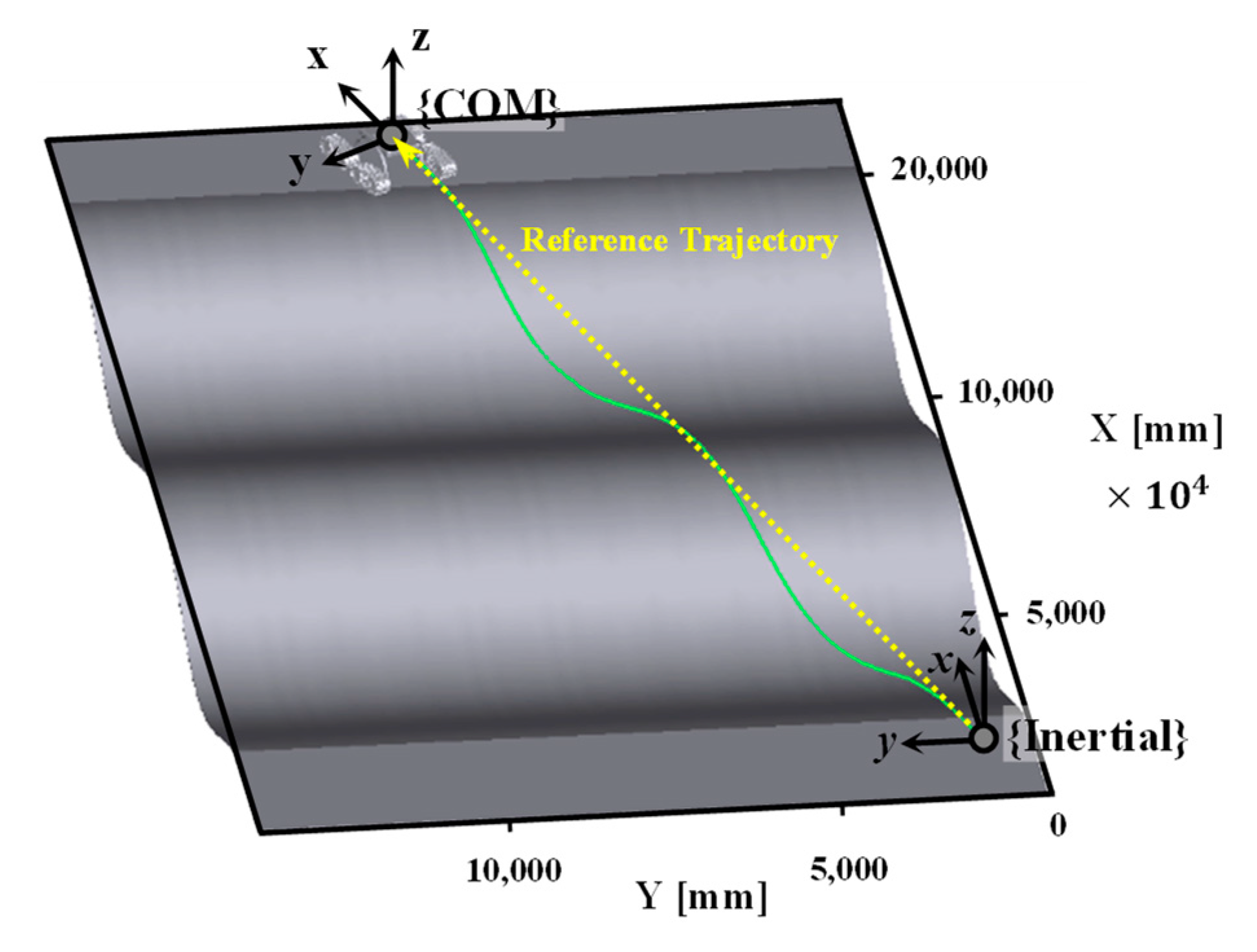
| Terrain | Total length | 22,000 mm |
| Total width | 14,000 mm | |
| Amplitude | 629 mm | |
| Period | 8800 mm | |
| Reference (in inertial frame) | Velocity | 1000 mm/s |
| Trajectory | Straight Line | |
| Initial Posture (in inertial frame) | Position | Origin (0,0) |
| Orientation | ||
| Simulation | Sampling time | 1 ms (Total 22 s) |
| Step | 22,000 | |
| Posture error gain | 1 | |
| Track Friction Coefficient | Dynamic | 1 |
| Static | 1.4 |
| Author | Performance Index | Analysis Model | Driving Terrain |
|---|---|---|---|
| Takafumi Haji et al. [22] | Maneuverability | Dynamics model in 3D space | Flat ground |
| Michaud, S., & Richter, L [23] | Terrainability Trafficability | Dynamics model in 3D space | Stairs and blocks |
| Zhang, Peng et al. [24] | Terrainability Trafficability | Dynamics model in 3D space | blocks |
| Ding, Liang et al. [25] | Terrainability Maneuverability Trafficability | Dynamics model in 3D space | Rough terrains |
| Thueer, T., and Siegwart, R [26] | Terrainability | Dynamics model in 3D space | Stairs and blocks |
| Deng, Zongquan et al. [27] | Trafficability | Statics and kinematics model in 2D plane | Stairs and blocks |
| Gupta, A. K., & Gupta, V. K [28] | Terrainability Maneuverability | Dynamics model in 3D space | Stairs and slope |
| Nathaniel Steven Michaluk [29] | ESLV CESLV | Dynamics model in 2D plane | Blocks and slope |
| Paez, L., and Melo, K [30] | Terrainability, Maneuverability, Trafficability and Efficiency | Statics and kinematics model in 2D plane | Flat ground |
| Performance Index | 4-Track SSMR | 4-Track SSMR with Suspension | |
|---|---|---|---|
| RMS distance error [mm] | 130.8 | 87.2 | 43.6 [33.3%] |
| RMS direction error [Deg] | 4.8 | 2.1 | 2.7 [56.3%] |
| RMS offset error [mm] | 111.3 | 63.2 | 48.1 [43.2%] |
| RSM Error | Four Track SSMR | PASTRo | ||||
|---|---|---|---|---|---|---|
| Conventional Planar SSMR Kinematics | TTCA Based Driving Velocity Projection | Velocity Propagation Based Driving Velocity Projection | ||||
| Distance error [mm] | 130.8 | 87.2 [** 33.3%] | 79.5 | [** 39.2%, * 8.8%] | 84.3 | [** 35.5%, * 3.3%] |
| Direction error [deg] | 4.8 | 2.1 [** 56.3%] | 2.0 | [** 57.9%, * 3.8%] | 2.2 | [** 54.8%, * −3.3%] |
| Offset error [mm] | 111.3 | 63.2 [** 43.2%] | 53.5 | [** 51.9%, * 15.4%] | 55.7 | [** 49.9%, * 11.8%] |
Disclaimer/Publisher’s Note: The statements, opinions and data contained in all publications are solely those of the individual author(s) and contributor(s) and not of MDPI and/or the editor(s). MDPI and/or the editor(s) disclaim responsibility for any injury to people or property resulting from any ideas, methods, instructions or products referred to in the content. |
© 2023 by the authors. Licensee MDPI, Basel, Switzerland. This article is an open access article distributed under the terms and conditions of the Creative Commons Attribution (CC BY) license (https://creativecommons.org/licenses/by/4.0/).
Share and Cite
Jeon, H.; Lee, D. Explicit Identification of Pointwise Terrain Gradients for Speed Compensation of Four Driving Tracks in Passively Articulated Tracked Mobile Robot. Mathematics 2023, 11, 905. https://doi.org/10.3390/math11040905
Jeon H, Lee D. Explicit Identification of Pointwise Terrain Gradients for Speed Compensation of Four Driving Tracks in Passively Articulated Tracked Mobile Robot. Mathematics. 2023; 11(4):905. https://doi.org/10.3390/math11040905
Chicago/Turabian StyleJeon, Haneul, and Donghun Lee. 2023. "Explicit Identification of Pointwise Terrain Gradients for Speed Compensation of Four Driving Tracks in Passively Articulated Tracked Mobile Robot" Mathematics 11, no. 4: 905. https://doi.org/10.3390/math11040905
APA StyleJeon, H., & Lee, D. (2023). Explicit Identification of Pointwise Terrain Gradients for Speed Compensation of Four Driving Tracks in Passively Articulated Tracked Mobile Robot. Mathematics, 11(4), 905. https://doi.org/10.3390/math11040905