Abstract
Cost-effective, lightweight design alternatives for the thermal management of heat transfer equipment are required. In this study, porous plate and perforated-porous plates are used for nanoliquid convection control in a flexible-walled vented cavity system under uniform magnetic field effects. The finite element technique is employed with the arbitrary Lagrangian–Eulerian (ALE) method. The numerical study is performed for different values of Reynolds number (), Hartmann number (), Cauchy number () and Darcy number (). At Re = 600, the average Nusselt number (Nu) is 6.3% higher by using a perforated porous plate in a cavity when compared to a cavity without a plate, and it is 11.2% lower at Re = 1000. At the highest magnetic field strength, increment amounts of Nu are in the range of 25.4–29.6% by considering the usage of plates. An elastic inclined wall provides higher Nu, while thermal performance improvements in the range of 3.6–6% are achieved when varying the elastic modulus of the wall. When using a perforated porous plate and increasing its permeability, 22.8% increments of average Nu are obtained. A vented cavity without a plate and elastic wall provides the highest thermal performance in the absence of a magnetic field, while using a porous plate with an elastic wall results in higher Nu when a magnetic field is used.
Keywords:
elastic wall; porous plate; perforated porous plate; finite element method; magnetic field; convective heat transfer MSC:
76D25; 76D55; 80M10; 80M50; 76S05
1. Introduction
Convection control in enclosures with ventilation ports is an important topic in thermal engineering. The applications are encountered in drying, the ventilation of buildings, electronic equipment cooling, the removal of contamination, chemical processing and many others [1,2,3]. The flow field exhibits complex pattern formation, while port size/number/location and other operating parameters, such as flow rates and thermal boundary conditions, are influential on the convective heat transfer (HT) rates from vented cavity (VC) systems. To better understand the heat transport mechanism and flow behavior in VC systems, many studies (theoretical and experimental) have been considered [4,5,6,7]. Many advancements were achieved for thermal process intensification in V-Cs by using available methods in HT enhancements. In one of the methods, elastic objects of flexible walls were considered [8,9,10,11]. The coupled fluid–structure interaction (FSI) problem has been considered in different thermal applications [12,13,14]. The type, size and elastic modulus of the wall/object are influential on the overall thermal performance improvements. As the wall is deformed due to the pressure forces exerted on it, additional control of flow in cavities and chambers are achieved, which depends upon the amount of deformation. In cavities, elastic walls have been considered in several studies, while the HT improvement amounts were primarily dependent upon the elastic modulus of the structure and other operating parameters [15,16]. In VC applications, deformable walls/objects have been considered in a few works.
The insertion of porous plates (PP) can be considered another method for convection control. The utilization of porous–fluid coupled systems can be encountered in micro-fluidic devices, packed bed reactors and many other thermal science applications [17,18,19,20]. Porous layers provide a good control option for convection intensification due to the large HT surface area effective HT mechanism inside the pores. In convective HT, thermal performance improvements have been obtained by the utilization of PPs or porous objects [21,22,23,24]. In this work, perforated porous plates (PPPs) are offered for convection control of the VC system. As the need for compact and lightweight structure of HT equipment is growing due to the cost, transportation and other issues, design alternatives of PPs in thermal science are a useful contribution to the existing literature. In VC, porous layers have been considered. Selimefendigil and Öztop [25] used a porous layer for convective HT in a U-shaped corrugated cavity. Significant variations in the flow and HT features were reported by the utilization of PL and varying its permeability. In the work of [26], mixed convective HT in a ventilated cavity filled with porous medium was analyzed by using the finite difference method. For the highest value of Darcy number (Da), they observed convection cell establishment inside the enclosure. Ataei-Dadavi et al. [27] performed experimental analysis on the mixed convection HT in a VC filled with a porous medium. They considered large solid and low-conductivity spheres while an analysis was performed for different values of the Richardson number (Ri). Measurements were made with PIV and liquid crystal thermography. They observed different flow regimes while the Nu correlation, covering all of the regimes, was developed. Additional works that considered the utilization of porous media, PL and PP in VC systems can be found in Refs. [28,29,30,31].
In this study, the nano-enhanced magnetic field (MGF) is used in the VC domain. The utilization of MGF effects is relevant in medical technology, microfluidic pumps, refrigeration, convective HT and many others [32,33,34,35]. An external MGF is used for flow and HT control, and it can be partially active and non-uniform. In various studies of HT, MGF and its parameters have been shown to be very influential on convective HT control [36,37,38,39,40,41]. Depending upon the application, MGF may be used for HT intensification, especially for flow with separation as encountered in channels with area expansion and in VC systems [42,43,44,45]. In the work of Kasaeipoor et al. [46], mixed convection in T-shaped VC was examined under MGF effects. The strength of the MGF was considered for Hartmann numbers (Ha) between 0 and 80. It was noted that at lower Re values, the average Nu was increased with higher Ha but it was more pronounced at higher Re values. Selimefendigil and Oztop [47] studied the mixed convective HT and entropy generation in a VC under inclined MGF effects. They observed that at lower Re, imposing MGF resulted in HT increment at the highest strength. When the Ha value was increased, both increments and decrements of total entropy generation were observed. The inclusion of nano-sized particles in HT fluids has been considered in many technological systems and energy-related technology, such as in solar applications, thermal management, refrigeration, energy storage, convective HT and many others [48,49,50,51]. The utilization of nanofluids in MGF has the potential to increase its effectiveness in convection with favorable impacts on using nano-sized particles in the electrical and thermal conductivity of base fluid [52,53]. Nanofluid applications with MGF for convective HT in VC have been considered in many studies [54,55,56,57]. The potential improvements of using MGF in thermal systems can be further enhanced by using nanofluids; the improvement amount depends upon the nano-sized particle shape, type, and its size, along with other operating parameters.
In this work, the computational fluid dynamics (CFDs) study of magnetohydrodynamics (MHDs) of a hybrid nanofluid in a VC is performed by using the combined utilization of an elastic inclined wall and PPP. The presence of the perforated plates instead of full PPs enables a lightweight and cost-effective solution for the management of thermal convection in a VC system. The inclusion of MGF and flexible wall effects can be intentionally considered, or they may be present within thermal application. The coupled effects of FSI with MGF effects in an enclosure with installed PPP are analyzed, and parameters of this novel control method are used for the thermal management and thermal performance improvement of the VC system. The outcomes are useful for thermal design and optimization studies related to electronic cooling, waste heat recovery systems, convective drying and many different HT equipment.
2. Modeling Approach
The forced convection of nanofluid in a VC with an inclined elastic side wall is analyzed under MGF effects. Porous plates (PPs) and perforated porous plates are used in the VC configuration. Figure 1 and Figure 2 show the schematic view of the thermo-fluid systems. The VC has a port size of wi = wo = w = 0.25H, while its size is H. The left wall of the VC is inclined and elastic (elastic modulus of E) with a 45 degree inclination angle. Cold fluid velocity and temperature are uc and Tc at the entrance of the VC, while the bottom wall is isothermal at T = Th. Other walls are considered adiabatic. Square PP with size of a = 0.4H is installed at the corner location of (xc, yc) = (0.5H − 0.5a, 0.5H − 0.5a) in the VC system. When PPP is used, nine identical circular cylinders of radius r = 0.1a are used in the PP with distance of d = 3r between the center locations of the cylinders. Uniform external MGF is imposed with strength of B0 and inclination of with the horizontal axis. The flow is 2D and laminar, and impacts of radiation, natural convection and viscous dissipation are not considered. In MHD flow, the impacts of joule heating along with the induced magnetic field and displacement currents are not taken into account. As the HT fluid, the hybrid nanofluid of water with Ag-MgO nanoparticles is used, while the solid volume fraction is taken as .
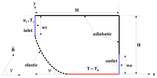
Figure 1.
Schematic view of VC system with inclined elastic wall under MGF.
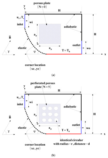
Figure 2.
Different configurations of VC system with PP (a) and with PPP (b).
Under the specified assumptions, and using the arbitrary Lagrangian–Eulerian (ALE) technique, the conservation equations for the nanofluid and solid domains are given as [58]
where u and w are the velocity vector and moving coordinate system velocity vector. Here, is the electrical conductivity, is the thermal diffusivity and B is the magnetic field. The MGF brings additional terms in the above given momentum equations, such as and , respectively. The denotes the MGF inclination angle. The equation in the FSI model for the solid domain is given as [11,58]
where is the imposed body force while and denote the solid stress tensor and acceleration.
In the PP and PPP domains, the generalized D-B-F extended model is used which can be given in expanded form as [59]
where , K and are the porosity, permeability and Forchheimer coefficient.
Reynolds number (Re), Prandtl number, Hartmann number (Ha) and Darcy number (Da) are the relevant non-dimensionless parameters, which are defined as
where is the characteristic length based on port size given as: .
In dimensional form, the explicit representation of the boundary conditions is given as follows:
- Inlet of VC, , .
- Exit of VC,
- Bottom wall of VC, .
- Other walls of VC, .
Traction equilibrium () and displacement compatibility () are used in the FSI model [11].
Thermal performance is evaluated based on the local and average Nu:
As the solution technique, the Galerkin weighted residual-finite element method is used. Field variable approximation is obtained by using shape functions ( and ) as [60,61]
where the values at the nodes are given by and T. Lagrange finite elements of different orders are utilized. The weighted residual is zero by using a weight function W as [60,61]
Streamline-upwind Petrov–Galerkin is used in the solver for handling the numerical instability, while the biconjugate gradient stabilized method is considered in the HT and flow module of the code. A converge criterion of 10 is considered. A commercial CFD software Comsol [62] is used for the numerical study.As the HT fluid, Ag-MgO hybrid nanoparticles are used in the base fluid to form the hybrid nanofluid.
Table 1 gives the nanoparticle and pure fluid thermophysical properties.

Table 1.
Thermophysical properties of hybrid nanoparticles and base fluid [63].
Experimental data were used in the study of [64] to derive a correlation for thermal conductivity and the viscosity of nanofluid. They are given as [64]
where is defined as:
The thermal conductivity relation is valid for solid volume fraction up to 3%, while viscosity is valid up to 2%. In the present work, solid volume fraction of 2% is used.
Mesh Independence and Validation of Code
Mesh independence tests are conducted to achieve the optimal grid distribution. MIT is shown for the average Nu versus grid sizes for two different MGF strengths as shown in Figure 3a. A grid system with 236,617 number of mixed elements (triangular+quadrilateral) is selected. Distribution of the grid is shown in Figure 3b, while refinement is seen near the walls and FSI interfaces.
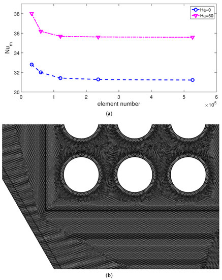
Figure 3.
Mesh independence test results for average Nu versus element number at two different MGF strength ((a), Re = 800, Ca = , Da = ) and distribution of mesh (b).
The first validation work was made by using the numerical results of Raisi and Arvin [65]. In the study, natural convective HT in a cavity with elastic walls and a thin flexible plate was analyzed. The Galerkin finite element method was used as the solver while the HT and flow characteristics for varying Rayleigh number (Ra) and baffle length were explored. The comparison results of streamlines at Ra = 10, E* = , s* = 6000 and baffle length of 0.8 are shown in Figure 4. The streamline variations are captured well by using the present code. The average Nu comparisons were also considered at two different Ra. At Ra = 10 and Ra = 10, the deviations between the average Nu are obtained as 3.9% and 0.75%, respectively. In another validation, forced convective HT in a VC having one inlet and one outlet port was analyzed, while the numerical data of Saeidi and Khodadadi [1] were used. Different port sizes and various Re were considered while a finite-volume-based solver was used. Figure 5 shows the average Nu comparisons at two different Re. The differences between the reference results are below 3%.
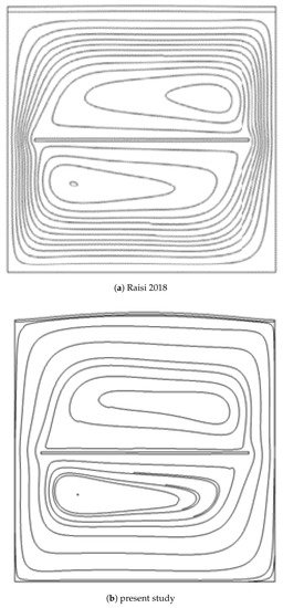
Figure 4.
Streamline comparisons by using the reference study in Ref. [65], where convection in a flexible walled enclosure with an elastic baffle was analyzed (Ra = 10, E* = , s* = 6000 and baffle length of 0.8).
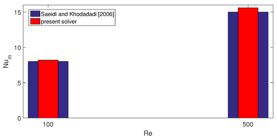
Figure 5.
Average Nu comparisons between the results of Ref. [1] at two different Re where forced convection in a VC with one inlet/outlet port is studied.
3. Results and Discussion
Forced convection control in a VC by combined utilization of elastic wall, PPP and uniform inclined MGF effects is considered. Different configurations of VC without plates and by using PP and PPP are compared in terms of thermal performance improvements. The thermo-fluid simulations are considered for the following range of parameters: , , , and . The case N = 0 denotes the VC with PP, and N = 9 is the case where nine identical inner circular objects of radius r are taken from the PP to obtain the PPP configuration. The MGF is uniform throughout the domain and its inclination is 45 degrees with the horizontal axis.
Impacts of Re on flow pattern are shown in Figure 6 for different cases of using inner PP. When there is no object in the VC, recirculation zones are formed below the inlet port at higher Re values. At the highest Re, near the corner of the upper wall, a secondary vortex is established, which was observed within the VC domain as shown in the previous studies. When PP is installed, the flow field is slightly impacted at low values of Re. However, using a PPP with N = 9 results in suppression of the vortex near the inlet and on the upper right corner. The internal structure of the PP resists more for the fluid flowing in the interior of the plate due to the inner circles while the main fluid stream from the inlet to outlet port is affected more. As the Re value is increased for the case of using PPP, the vortex size below the inlet port increases but it is not significant as compared to other cases using PP and no object. Local Nu variations along the hot bottom wall generally rise with higher Re in the absence and presence of PPP. However, in the case of using no plate, the local Nu is higher for lower Re, which is due to the vortex formation near the inlet and its extension toward the bottom wall. This phenomenon is not seen when PPP is installed. This is due to the suppression of this vortex. However, higher peak values of local Nu are lower when using PPP due to the weak spreading of the cold fluid over the hot surface. Average Nu is generally higher when using PP, but the worst case in terms of thermal performance at Re = 800 and Re = 1000 is seen when PPP is used. At Re = 1000, the average Nu is 11.2% lower for the case with PPP as compared to VC without a plate, while it is 3% higher when PP is used. At Re = 600, the average Nu is 6.3% higher by using PPP as compared to the reference case of VC without a plate (Figure 7).
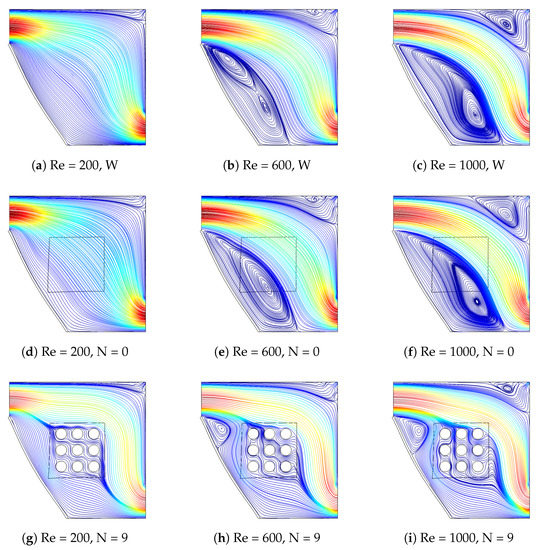
Figure 6.
Impacts of Re on the streamline variations for different cases of using PPs (Ha = 15, Ca = , Da = ).
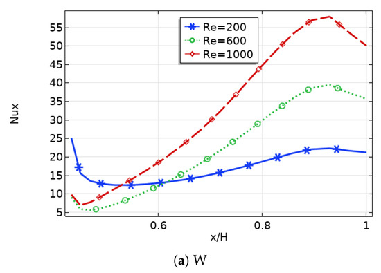
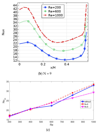
Figure 7.
Local (a,b) and average (c) Nu variations with different Re for different cases of using PPs (Ha = 15, Ca = , Da = ).
The imposed MGF is uniform throughout the computational domain while it is inclined with angle of 45 degrees. When MGF is used, recirculation zones are suppressed as it has been shown in many studies involving flow separation. When MGF strength is increased to Ha = 10, slight changes in the vortex below the inlet port are seen while fluid velocity is reduced. At the highest MGF strength, vortex suppression is profound for the VC without a plate (Figure 8). As the PPP is installed, the vortex size is small and, therefore, impacts of using MGF on the flow field is not as significant as compared to other cases. This is also shown in the local Nu variation as shown in Figure 9. When no plate is used, increasing the MGF strength from Ha = 0 to Ha = 10 reduces the local Nu as the fluid velocity is reduced. In this case, vortex suppression is not significant. When its strength is increased to Ha = 50, local Nu becomes higher on the left portion of the hot wall due to the vortex suppression. However, local Nu becomes higher in the large portion of the hot wall with higher MGF strength when PPP is mounted in the VC. When average Nu performance results are compared, its value is reduced until Ha = 20 for the cases without a plate and PP (N = 0), while its value is increased further with higher MGF strength. When the no-plate case and PP case are considered, the balance between the vortex suppression due to higher Lorentz forces and reduction of main fluid velocity with higher MGF strengths results in lower values of average Nu. When no plate is used, the average Nu is reduced 39.6% from Ha = 0 to Ha = 20, while it is increased 29.6% from Ha = 20 to Ha = 50. When PP is used with N = 0, these values become 22.2% and 26.5%. The average Nu rises by about 25.4% at the highest MGF strength when PPP is mounted in the VC system.
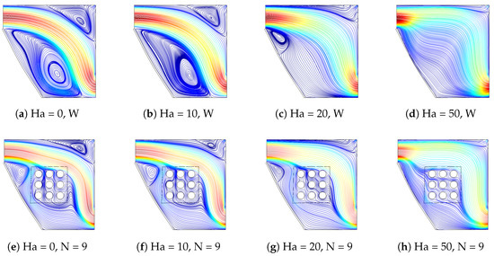
Figure 8.
Streamline variations with different MGF strength for VC system without plate (a–d) and with PPP (e–h) (Re = 800, Ca = , Da = ).
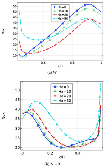
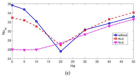
Figure 9.
Impacts of MGF strength on local (a,b) and average (c) Nu variations by using different PP configurations (Re = 800, Ca = , Da = ).
The left inclined wall of the VC is made elastic. Variations of the elastic modulus of the inclined wall on the flow pattern variations are shown in Figure 10. A lower value of Ca denotes a rigid wall, where the elastic modulus is higher. The deflection of the left inclined wall results in changes in the vortex core center below in the inlet port, while this impact is more pronounced when the MGF effect is absent. As part of the fluid impinges onto the inclined wall, deformation of the wall is more pronounced for higher fluid velocities (lower MGF strength) and for higher Ca values. The local Nu is generally higher for higher values of Ca. This is due to the movement of the main fluid stream toward the left due to the additional deformation caused by the elastic inclined wall. The average Nu values are lower when a rigid wall is used for all plates while higher HT values are achieved for the case when PP is installed. The amount of average Nu rise becomes 6% and 3.6% and 2.6% for VC system with PPP (N = 9), PP (N = 0) and without a plate, respectively (Figure 11). The permeability of the PP is also another influencing factor for convective HT features. When PP (N = 0) is used with lower permeability (lower Da values), the plate resists more against the fluid flow while the vortex size below the inlet ports is small. When the Da value is increased, its size increases and the secondary vortex near the top right corner becomes more pronounced (Figure 12). However, for the PPP (N = 9), due to the presence of the internal circular voids, the impact of permeability on the flow structure is not as significant as for the case of PP (N = 0). The local Nu becomes higher with higher permeability for the large portion of the hot wall. When PPP is used, the average Nu increment becomes 22.8%, while it is 35.9% for the PP (N = 9) case (Figure 13).
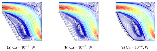
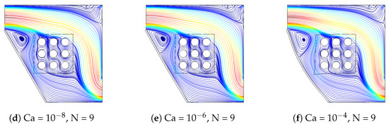
Figure 10.
Impacts of Ca number of the streamline variations for the VC system without plate (a–c) and with PPP (d–f) (Re = 800, Ha = 15, Da = ).
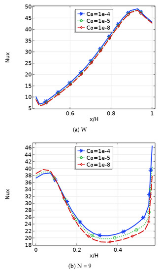
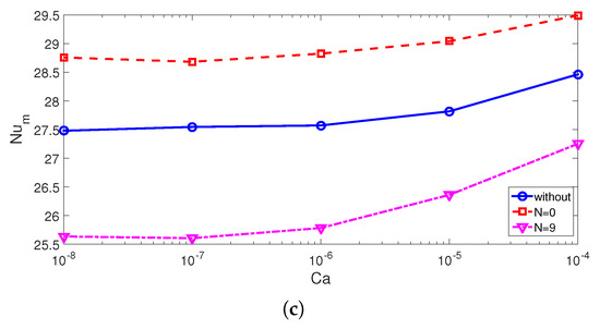
Figure 11.
Effects of Ca number on the local (a,b) and average (c) Nu distributions for different cases of using PP (Re = 800, Ha = 15, Da = ).
Figure 12.
Streamline distributions with varying permeability of PPs (a–c) and PPP (d–f) (Re = 800, Ha = 15, Ca = ).
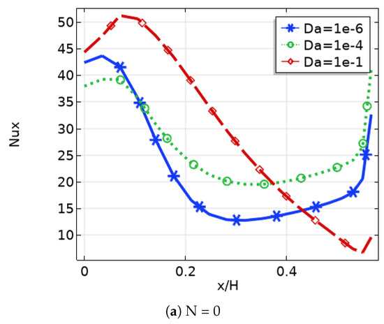
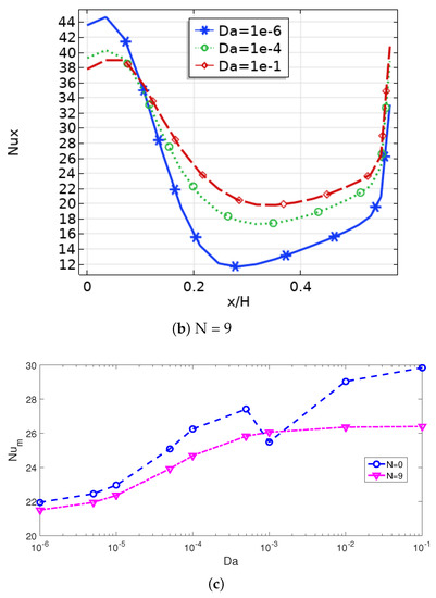
Figure 13.
Impacts of Da on the variation of local (a,b) and average Nu (c) for the cases without plate (W) and with PPP (Re = 800, Ha = 15, Ca = ).
Different case comparisons in terms of thermal performance improvements are shown in Figure 14. In the absence of MGF effects, the best case is obtained when no object is used for the elastic-walled VC system, while the worst case is seen for the PPP-installed VC with a rigid side wall. The reduction amounts of average Nu are 27.5% and 24.5% by using a PPP as compared to the case without a plate for the rigid and elastic-walled cavity cases. When MGF effects are considered, the PP case provides the highest value of average Nu. The values when using PP are 5.5% higher as compared to the case of VC without a plate. Even though PPP provides a lightweight structure of the VC system, it provides HT deterioration, and using it is not advantageous at the highest permeability of the plate. However, using a PP in the VC system provides higher local and average Nu values under MGF effects, and it can be considered a good tool for the thermal management of thermo-fluid configuration.
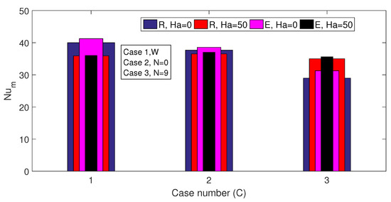
Figure 14.
Comparison of different cases (MGF, PPP and elastic wall) in terms of thermal performance enhancement.
4. Conclusions
In the present study, the effects of using elastic wall, PPP and uniform inclined MGF on the convective thermal performance improvements in a VC are numerically assessed. A novel configuration of using a perforated porous plate and inclined elastic wall is proposed for HT control under MGF effects. The following conclusions can be drawn:
- Significant variations in the flow patterns are observed when PPP is installed and MGF strength is varied. Depending upon the Re value, using PPP results in thermal performance improvements. At Re = 600, HT rates becomes 6.3% higher when using PPP as compared to the case of a cavity without a plate, while it is 11.2% lower at Re = 1000.
- HT rates become lower with higher MGF strength until a certain value of Ha, and beyond this value, they become higher for different cases of using PPs. Average Nu increments from Ha = 20 to Ha = 50 are obtained as 29.6%, 29.6% and 25.4% when using no plate, PP and PPP, respectively.
- The variation of the elastic modulus of the inclined wall contributes to the HT rates, while for a rigid wall, lower HT rates are seen. The highest impact is obtained for VC system with PPP (6% increment), followed by VC with PP (3.6% increment). When the permeability of the plates is increased, it has a positive impact on the thermal performance improvement, while HT increments of 22.8% and 35.9% are obtained by using the VC system with PPP and with PP.
- When MGF is not used, the most favorable case in terms of thermal performance is the configuration without a plate and elastic wall, while the worst case is with PPP and a rigid side wall. When MGF is used, the bast case is the VC system with PP, while the HT rate is 5.5% higher as compared to the case without a plate.
The present study can be extended to include non-uniform MGF effects, multiple port inclusion and different thermal boundary conditions. Entropy generation analysis can also be included, which will increase the applicability of the present study.
Author Contributions
Conceptualization, F.S.; methodology, F.S.; software, F.S.; validation, L.K.; formal analysis, F.S., H.R. and M.O.; investigation, F.S., B.A., B.M.A. and L.K.; writing—original draft preparation, F.S.; writing—review and editing, F.S., H.R., M.O., C.M., B.A., B.M.A. and L.K.; visualization, F.S. and L.K.; supervision, F.S., L.K., H.R., M.O. and C.M. All authors have read and agreed to the published version of the manuscript.
Funding
This research work was funded by Institutional Fund Projects under grant no. (IFPIP-500-135-1443). Therefore, the authors gratefully acknowledge technical and financial support from the Ministry of Education and King Abdulaziz University, Jeddah, Saudi Arabia.
Institutional Review Board Statement
Not applicable.
Informed Consent Statement
Not applicable.
Data Availability Statement
Not applicable.
Conflicts of Interest
The authors declare no conflict of interest.
Abbreviations
| a | plate size |
| B | strength of magnetic field |
| Da | Darcy number |
| d | distance between the cylinders |
| E | elastic modulus |
| Ha | Hartmann number |
| H | cavity size |
| h | heat transfer coefficient |
| k | thermal conductivity |
| n | unit normal vector |
| Nu | Nusselt number |
| p | pressure |
| Pr | Prandtl number |
| r | cylinder size |
| Re | Reynolds number |
| T | temperature |
| u, v | velocity components |
| wi | inlet port size |
| wo | outlet port size |
| x, y | Cartesian coordinates |
| Greek Characters | |
| thermal diffusivity | |
| solid volume fraction | |
| inclination angle | |
| kinematic viscosity | |
| non-dimensional temperature | |
| density | |
| electrical conductivity | |
| Subscripts | |
| c | cold |
| h | hot |
| m | average |
| hnf | hybrid nanofluid |
| Subscripts | |
| HT | heat transfer |
| MGF | magnetic field |
| PP | porous plate |
| PPP | perforated porous plate |
| VC | vented cavity |
References
- Saeidi, S.M.; Khodadadi, J. Forced convection in a square cavity with inlet and outlet ports. Int. J. Heat Mass Transf. 2006, 49, 1896–1906. [Google Scholar] [CrossRef]
- Velazquez, A.; Arias, J.; Montanes, J. Pulsating flow and convective heat transfer in a cavity with inlet and outlet sections. Int. J. Heat Mass Transf. 2009, 52, 647–654. [Google Scholar] [CrossRef]
- Selimefendigil, F.; Oztop, H.F. Fluid-solid interaction of elastic-step type corrugation effects on the mixed convection of nanofluid in a vented cavity with magnetic field. Int. J. Mech. Sci. 2019, 152, 185–197. [Google Scholar] [CrossRef]
- Mahmoudi, A.H.; Shahi, M.; Talebi, F. Effect of inlet and outlet location on the mixed convective cooling inside the ventilated cavity subjected to an external nanofluid. Int. Commun. Heat Mass Transf. 2010, 37, 1158–1173. [Google Scholar] [CrossRef]
- Ismael, M.A.; Jasim, H.F. Role of the fluid-structure interaction in mixed convection in a vented cavity. Int. J. Mech. Sci. 2018, 135, 190–202. [Google Scholar] [CrossRef]
- Radhakrishnan, T.; Verma, A.; Balaji, C.; Venkateshan, S. An experimental and numerical investigation of mixed convection from a heat generating element in a ventilated cavity. Exp. Therm. Fluid Sci. 2007, 32, 502–520. [Google Scholar] [CrossRef]
- Selimefendigil, F.; Öztop, H.F. Thermal management and performance improvement by using coupled effects of magnetic field and phase change material for hybrid nanoliquid convection through a 3D vented cylindrical cavity. Int. J. Heat Mass Transf. 2022, 183, 122233. [Google Scholar] [CrossRef]
- Selimefendigil, F.; Öztop, H.F. Effects of an inner stationary cylinder having an elastic rod-like extension on the mixed convection of CNT-water nanofluid in a three dimensional vented cavity. Int. J. Heat Mass Transf. 2019, 137, 650–668. [Google Scholar] [CrossRef]
- Khanafer, K.; Vafai, K.; Gaith, M. Fluid-structure interaction analysis of flow and heat transfer characteristics around a flexible microcantilever in a fluidic cell. Int. Commun. Heat Mass Transf. 2016, 75, 315–322. [Google Scholar] [CrossRef]
- Ismael, M.A. Forced convection in partially compliant channel with two alternated baffles. Int. J. Heat Mass Transf. 2019, 142, 118455. [Google Scholar] [CrossRef]
- Khanafer, K. Comparison of flow and heat transfer characteristics in a lid-driven cavity between flexible and modified geometry of a heated bottom wall. Int. J. Heat Mass Transf. 2014, 78, 1032–1041. [Google Scholar] [CrossRef]
- Shahabadi, M.; Mehryan, S.; Ghalambaz, M.; Ismael, M. Controlling the natural convection of a non-Newtonian fluid using a flexible fin. Appl. Math. Model. 2021, 92, 669–686. [Google Scholar] [CrossRef]
- Ghalambaz, M.; Mehryan, S.; Ismael, M.A.; Chamkha, A.; Wen, D. Fluid–structure interaction of free convection in a square cavity divided by a flexible membrane and subjected to sinusoidal temperature heating. Int. J. Numer. Methods Heat Fluid Flow 2019, 30, 2883–2911. [Google Scholar] [CrossRef]
- Alsabery, A.; Selimefendigil, F.; Hashim, I.; Chamkha, A.; Ghalambaz, M. Fluid-structure interaction analysis of entropy generation and mixed convection inside a cavity with flexible right wall and heated rotating cylinder. Int. J. Heat Mass Transf. 2019, 140, 331–345. [Google Scholar] [CrossRef]
- Selimefendigil, F.; Öztop, H.F.; Abu-Hamdeh, N. Impacts of conductive inner L-shaped obstacle and elastic bottom wall on MHD forced convection of a nanofluid in vented cavity. J. Therm. Anal. Calorim. 2020, 141, 465–482. [Google Scholar] [CrossRef]
- Sabbar, W.A.; Ismael, M.A.; Almudhaffar, M. Fluid-structure interaction of mixed convection in a cavity-channel assembly of flexible wall. Int. J. Mech. Sci. 2018, 149, 73–83. [Google Scholar] [CrossRef]
- Chamkha, A.J.; Ismael, M.A. Natural convection in differentially heated partially porous layered cavities filled with a nanofluid. Numer. Heat Transf. Part A Appl. 2014, 65, 1089–1113. [Google Scholar] [CrossRef]
- Alsabery, A.; Chamkha, A.; Hussain, S.H.; Saleh, H.; Hashim, I. Heatline visualization of natural convection in a trapezoidal cavity partly filled with nanofluid porous layer and partly with non-Newtonian fluid layer. Adv. Powder Technol. 2015, 26, 1230–1244. [Google Scholar] [CrossRef]
- Miroshnichenko, I.V.; Sheremet, M.A.; Oztop, H.F.; Abu-Hamdeh, N. Natural convection of alumina-water nanofluid in an open cavity having multiple porous layers. Int. J. Heat Mass Transf. 2018, 125, 648–657. [Google Scholar] [CrossRef]
- Ayoubloo, K.A.; Ghalambaz, M.; Armaghani, T.; Noghrehabadi, A.; Chamkha, A.J. Pseudoplastic natural convection flow and heat transfer in a cylindrical vertical cavity partially filled with a porous layer. Int. J. Numer. Methods Heat Fluid Flow 2019, 30, 1096–1114. [Google Scholar] [CrossRef]
- Astanina, M.S.; Sheremet, M.A.; Oztop, H.F.; Abu-Hamdeh, N. MHD natural convection and entropy generation of ferrofluid in an open trapezoidal cavity partially filled with a porous medium. Int. J. Mech. Sci. 2018, 136, 493–502. [Google Scholar] [CrossRef]
- Selimefendigil, F.; Öztop, H.F. Optimization of convective heat transfer performance for fluid flow over a facing step by using an elliptic porous object. Case Stud. Therm. Eng. 2021, 27, 101233. [Google Scholar] [CrossRef]
- Siavashi, M.; Yousofvand, R.; Rezanejad, S. Nanofluid and porous fins effect on natural convection and entropy generation of flow inside a cavity. Adv. Powder Technol. 2018, 29, 142–156. [Google Scholar] [CrossRef]
- Ranjbar, A.M.; Pouransari, Z.; Siavashi, M. Improved design of heat sink including porous pin fins with different arrangements: A numerical turbulent flow and heat transfer study. Appl. Therm. Eng. 2021, 198, 117519. [Google Scholar] [CrossRef]
- Selimefendigil, F.; Öztop, H.F. Magnetohydrodynamics forced convection of nanofluid in multi-layered U-shaped vented cavity with a porous region considering wall corrugation effects. Int. Commun. Heat Mass Transf. 2020, 113, 104551. [Google Scholar] [CrossRef]
- Gibanov, N.S.; Sheremet, M.A.; Ismael, M.A.; Chamkha, A.J. Mixed convection in a ventilated cavity filled with a triangular porous layer. Transp. Porous Media 2017, 120, 1–21. [Google Scholar] [CrossRef]
- Ataei-Dadavi, I.; Chakkingal, M.; Kenjeres, S.; Kleijn, C.R.; Tummers, M.J. Experiments on mixed convection in a vented differentially side-heated cavity filled with a coarse porous medium. Int. J. Heat Mass Transf. 2020, 149, 119238. [Google Scholar] [CrossRef]
- Javadzadegan, A.; Joshaghani, M.; Moshfegh, A.; Akbari, O.A.; Afrouzi, H.H.; Toghraie, D. Accurate meso-scale simulation of mixed convective heat transfer in a porous media for a vented square with hot elliptic obstacle: An LBM approach. Phys. A Stat. Mech. Its Appl. 2020, 537, 122439. [Google Scholar] [CrossRef]
- Gokulavani, P.; Muthtamilselvan, M.; Abdalla, B. Impact of injection/suction and entropy generation of the porous open cavity with the hybrid nanofluid. J. Therm. Anal. Calorim. 2022, 147, 3299–3312. [Google Scholar] [CrossRef]
- Selimefendigil, F.; Öztop, H.F. Combined effects of using multiple porous cylinders and inclined magnetic field on the performance of hybrid nanoliquid forced convection. J. Magn. Magn. Mater. 2023, 565, 170137. [Google Scholar] [CrossRef]
- Alawee, W.H.; Al-Sumaily, G.F.; Dhahad, H.A.; Thompson, M.C. Numerical analysis of non-Darcian mixed convection flows in a ventilated enclosure filled with a fluid-saturated porous medium. Therm. Sci. Eng. Prog. 2021, 24, 100922. [Google Scholar] [CrossRef]
- Nkurikiyimfura, I.; Wang, Y.; Pan, Z. Heat transfer enhancement by magnetic nanofluids—A review. Renew. Sustain. Energy Rev. 2013, 21, 548–561. [Google Scholar] [CrossRef]
- Al-Habahbeh, O.; Al-Saqqa, M.; Safi, M.; Khater, T.A. Review of magnetohydrodynamic pump applications. Alex. Eng. J. 2016, 55, 1347–1358. [Google Scholar] [CrossRef]
- Giwa, S.; Sharifpur, M.; Ahmadi, M.; Meyer, J. A review of magnetic field influence on natural convection heat transfer performance of nanofluids in square cavities. J. Therm. Anal. Calorim. 2021, 145, 2581–2623. [Google Scholar] [CrossRef]
- Alsabery, A.I.; Armaghani, T.; Chamkha, A.J.; Sadiq, M.A.; Hashim, I. Effects of two-phase nanofluid model on convection in a double lid-driven cavity in the presence of a magnetic field. Int. J. Numer. Methods Heat Fluid Flow 2018, 29, 1272–1299. [Google Scholar] [CrossRef]
- Hussain, S.; Armaghani, T.; Jamal, M. Magnetoconvection and entropy analysis in T-shaped porous enclosure using finite element method. J. Thermophys. Heat Transf. 2020, 34, 203–214. [Google Scholar] [CrossRef]
- Selimefendigil, F.; Chamkha, A.J. Magnetohydrodynamics mixed convection in a power law nanofluid-filled triangular cavity with an opening using Tiwari and Das’ nanofluid model. J. Therm. Anal. Calorim. 2019, 135, 419–436. [Google Scholar] [CrossRef]
- Armaghani, T.; Esmaeili, H.; Mohammadpoor, Y.; Pop, I. MHD mixed convection flow and heat transfer in an open C-shaped enclosure using water-copper oxide nanofluid. Heat Mass Transf. 2018, 54, 1791–1801. [Google Scholar] [CrossRef]
- Aich, W.; Selimefendigil, F.; Alqahtani, T.; Algarni, S.; Alshehery, S.; Kolsi, L. Thermal and Phase Change Process in a Locally Curved Open Channel Equipped with PCM-PB and Heater during Nanofluid Convection under Magnetic Field. Mathematics 2022, 10, 4070. [Google Scholar] [CrossRef]
- Izadi, M.; Sheremet, M.A.; Mehryan, S.; Pop, I.; Öztop, H.F.; Abu-Hamdeh, N. MHD thermogravitational convection and thermal radiation of a micropolar nanoliquid in a porous chamber. Int. Commun. Heat Mass Transf. 2020, 110, 104409. [Google Scholar] [CrossRef]
- Kolsi, L.; Selimefendigil, F.; Omri, M.; Ladhar, L. Combined Effects of Sequential Velocity and Variable Magnetic Field on the Phase Change Process in a 3D Cylinder Having a Conic-Shaped PCM-Packed Bed System. Mathematics 2021, 9, 3019. [Google Scholar] [CrossRef]
- Abbassi, H.; Nassrallah, S.B. MHD flow and heat transfer in a backward-facing step. Int. Commun. Heat Mass Transf. 2007, 34, 231–237. [Google Scholar] [CrossRef]
- Hussain, S.; Ahmed, S.E. Unsteady MHD forced convection over a backward facing step including a rotating cylinder utilizing Fe3O4-water ferrofluid. J. Magn. Magn. Mater. 2019, 484, 356–366. [Google Scholar] [CrossRef]
- Mehrez, Z.; El Cafsi, A. Forced convection magnetohydrodynamic Al2O3–Cu/water hybrid nanofluid flow over a backward-facing step. J. Therm. Anal. Calorim. 2019, 135, 1417–1427. [Google Scholar] [CrossRef]
- Selimefendigil, F.; Öztop, H.F. Hydro-thermal performance of CNT nanofluid in double backward facing step with rotating tube bundle under magnetic field. Int. J. Mech. Sci. 2020, 185, 105876. [Google Scholar] [CrossRef]
- Kasaeipoor, A.; Ghasemi, B.; Aminossadati, S. Convection of Cu-water nanofluid in a vented T-shaped cavity in the presence of magnetic field. Int. J. Therm. Sci. 2015, 94, 50–60. [Google Scholar] [CrossRef]
- Selimefendigil, F.; Oztop, H.F. Mixed convection and entropy generation of nanofluid flow in a vented cavity under the influence of inclined magnetic field. Microsyst. Technol. 2019, 25, 4427–4438. [Google Scholar] [CrossRef]
- Esfe, M.H.; Kamyab, M.H.; Valadkhani, M. Application of nanofluids and fluids in photovoltaic thermal system: An updated review. Sol. Energy 2020, 199, 796–818. [Google Scholar] [CrossRef]
- Arora, N.; Gupta, M. An updated review on application of nanofluids in flat tubes radiators for improving cooling performance. Renew. Sustain. Energy Rev. 2020, 134, 110242. [Google Scholar] [CrossRef]
- Kakaç, S.; Pramuanjaroenkij, A. Single-phase and two-phase treatments of convective heat transfer enhancement with nanofluids–A state-of-the-art review. Int. J. Therm. Sci. 2016, 100, 75–97. [Google Scholar] [CrossRef]
- Said, Z.; Sundar, L.S.; Tiwari, A.K.; Ali, H.M.; Sheikholeslami, M.; Bellos, E.; Babar, H. Recent advances on the fundamental physical phenomena behind stability, dynamic motion, thermophysical properties, heat transport, applications, and challenges of nanofluids. Phys. Rep. 2022, 946, 1–94. [Google Scholar] [CrossRef]
- Chamkha, A.J.; Jena, S.K.; Mahapatra, S.K. MHD convection of nanofluids: A review. J. Nanofluids 2015, 4, 271–292. [Google Scholar] [CrossRef]
- Sheikholeslami, M.; Rokni, H.B. Simulation of nanofluid heat transfer in presence of magnetic field: A review. Int. J. Heat Mass Transf. 2017, 115, 1203–1233. [Google Scholar] [CrossRef]
- Jamshed, W.; Eid, M.R.; Hussain, S.M.; Abderrahmane, A.; Safdar, R.; Younis, O.; Pasha, A.A. Physical specifications of MHD mixed convective of Ostwald-de Waele nanofluids in a vented-cavity with inner elliptic cylinder. Int. Commun. Heat Mass Transf. 2022, 134, 106038. [Google Scholar] [CrossRef]
- Benzema, M.; Benkahla, Y.K.; Labsi, N.; Ouyahia, S.E.; El Ganaoui, M. Second law analysis of MHD mixed convection heat transfer in a vented irregular cavity filled with Ag–MgO/water hybrid nanofluid. J. Therm. Anal. Calorim. 2019, 137, 1113–1132. [Google Scholar] [CrossRef]
- GeridÖnmez, B.P.; Öztop, H.F. Effects of partial magnetic field in a vented square cavity with aiding and opposing of MWCNT–water nanofluid flows. Eng. Anal. Bound. Elem. 2021, 133, 84–94. [Google Scholar] [CrossRef]
- Du, R.; Gokulavani, P.; Muthtamilselvan, M.; Al-Amri, F.; Abdalla, B. Influence of the Lorentz force on the ventilation cavity having a centrally placed heated baffle filled with the Cu- Al2O3- H2O hybrid nanofluid. Int. Commun. Heat Mass Transf. 2020, 116, 104676. [Google Scholar] [CrossRef]
- Mehryan, S.; Ghalambaz, M.; Ismael, M.A.; Chamkha, A.J. Analysis of fluid-solid interaction in MHD natural convection in a square cavity equally partitioned by a vertical flexible membrane. J. Magn. Magn. Mater. 2017, 424, 161–173. [Google Scholar] [CrossRef]
- Ghasemi, K.; Siavashi, M. MHD nanofluid free convection and entropy generation in porous enclosures with different conductivity ratios. J. Magn. Magn. Mater. 2017, 442, 474–490. [Google Scholar] [CrossRef]
- Roy, S.; Basak, T. Finite element analysis of natural convection flows in a square cavity with non-uniformly heated wall (s). Int. J. Eng. Sci. 2005, 43, 668–680. [Google Scholar] [CrossRef]
- Hashim, I.; Alsabery, A.; Sheremet, M.A.; Chamkha, A. Numerical investigation of natural convection of Al2O3-water nanofluid in a wavy cavity with conductive inner block using Buongiorno’s two-phase model. Adv. Powder Technol. 2019, 30, 399–414. [Google Scholar] [CrossRef]
- COMSOL. Manual Multiphysics, Comsol User’s Guide V. 5.4; COMSOL AB: Stockholm, Sweden, 2018. [Google Scholar]
- Ma, Y.; Mohebbi, R.; Rashidi, M.; Yang, Z. MHD convective heat transfer of Ag-MgO/water hybrid nanofluid in a channel with active heaters and coolers. Int. J. Heat Mass Transf. 2019, 137, 714–726. [Google Scholar] [CrossRef]
- Esfe, M.H.; Arani, A.A.A.; Rezaie, M.; Yan, W.M.; Karimipour, A. Experimental determination of thermal conductivity and dynamic viscosity of Ag–MgO/water hybrid nanofluid. Int. Commun. Heat Mass Transf. 2015, 66, 189–195. [Google Scholar] [CrossRef]
- Raisi, A.; Arvin, I. A numerical study of the effect of fluid-structure interaction on transient natural convection in an air-filled square cavity. Int. J. Therm. Sci. 2018, 128, 1–14. [Google Scholar] [CrossRef]
Disclaimer/Publisher’s Note: The statements, opinions and data contained in all publications are solely those of the individual author(s) and contributor(s) and not of MDPI and/or the editor(s). MDPI and/or the editor(s) disclaim responsibility for any injury to people or property resulting from any ideas, methods, instructions or products referred to in the content. |
© 2023 by the authors. Licensee MDPI, Basel, Switzerland. This article is an open access article distributed under the terms and conditions of the Creative Commons Attribution (CC BY) license (https://creativecommons.org/licenses/by/4.0/).