Abstract
For the wide frequency spectrum of chaotic signals, it is difficult to realize chaotic signal conditioning. Therefore, researchers turn to the exploration of chaotic systems with independent non-bifurcation control for easy chaos modification. In this paper, a system with only one non-quadratic term is modified for providing multiscale amplitude/frequency control. By adjusting the feedback with an odd higher degree term, a switchable chaotic oscillator is obtained, which provides the different scales of amplitude/frequency control with the chaotic signal. Multisim-based circuit simulation shows the efficiency and convenience of chaotic signal control.
MSC:
37M05; 34H10
1. Introduction
Chaos studies have shown great potential value in engineering applications in recent decades. Chaos is proven to help improve security in the field of communication and information [1,2]. Chaos-based image encryption has been studied with models and improved encryption algorithms, and the security and reliability of the encryption algorithm were proven [3,4]. Discrete memristors and their coupling maps are widely used for chaotic oscillations or neuromorphic computations [5,6]. Many chaos-based application schematics have been proposed combined with corresponding engineering technology [7,8]. Many memristive systems in neural networks show chaotic oscillation [9,10,11]. Moreover, many researchers focus on the synchronization [12,13] and multi-stability [14] of chaos and its applications. As we know, the broadband property of chaos [15,16,17] poses great difficulty in the conditioning of chaotic signals and the finding of non-bifurcation parameters [18] is a hot topic in the chaos community. The definition of partial and total amplitude control was first given in [19]. A relationship between symmetry and amplitude control was discussed in [20]. Furthermore, the concept of offset boosting was defined firstly in [21], which is applied in a system for the control of the average value, along with the system variable, by a single non-bifurcation offset parameter. Thereafter, more work has been carried out associated with amplitude control, offset boosting and even amplitude/frequency control, including the area of the memristive circuit [22] and hyperchaotic map [23]. In [23], a self-reproduction hyperchaotic map with compound lattice dynamics was proposed where the offset induced by the initial condition is applied for a lattice of coexisting attractors. In [24], the simplification of chaotic circuits with quadratic nonlinearity was first exhaustively explored, where a resistor can realize partial amplitude control. In [25], conditional symmetric systems were derived from a gallery of symmetric chaotic systems, where the amplitude of some variables can be controlled depending on the specific structure of symmetry, while the offset in a dimension can be boosted with a carefully selected initial condition.
Aiming to construct a new chaotic system with easy amplitude/frequency control, we noticed that a class of chaotic systems with only one non-quadratic term was proposed [26], where the amplitude-frequency control of chaos can be realized by a single parameter. Twelve chaotic systems were comprehensively given, where each system has its unique features but with a common property for amplitude/frequency modification. The variables of all these systems can be modified positively. Moreover, all the control is within a limited scale, which cannot satisfy the demanding of engineering applications. In this paper, the SL8 system in [26] is employed as a seed system for further modification, outputting various attractors for providing convenient multiscale amplitude/frequency control. Amplitude/frequency control exploration based on the SL8 system is also based on its elegant feedback and a line of equilibrium points giving more possibilities for chaos control. The structure of a system with only one non-quadratic term poses great convenience for amplitude/frequency control from a single coefficient of a non-quadratic term, which allows us to think of more possibilities for the non-quadratic term in view of feedback degree. In order to introduce different types of amplitude/frequency control, higher degree terms are introduced for comparison. When retaining the polarity of non-quadratic feedback, two new forms of feedback, cubic term and quintic term, are introduced for multiscale amplitude/frequency control. The corresponding chaotic circuit structure is maintained for amplitude-frequency control under three different scales. Based on this, a switchable chaotic oscillator is designed. The oscillator has the following characteristics.
- The oscillator has three independent amplitude/frequency control channels with different scales.
- The circuit shows flexibility in amplitude/frequency control, in which chaos modification is based on a sliding rheostat or a switch.
- The reuse of the multiplier makes the unified circuit simple, ensuring circuit reliability.
In the following, the revised model of system SL8 is given in Section 2. The property of amplitude/frequency control is analyzed in Section 3, where the demonstration of the signal waveform, power spectrum, phase trajectory and Lyapunov exponent spectrum is given. The circuit simulation is given in Section 4. Conclusions are drawn in the last section.
2. Modified Chaotic System for Multiscale Amplitude/Frequency Control
As proposed in [26], a single non-quadratic term wins amplitude/frequency control in a chaotic system. Here we select the SL8 system in [26] for revision of how to realize multiscale amplitude/frequency modification.
We here replace the linear term y in the x-dimension with y3 and y5 for chaos generation. In order to maintain the same structure and for the emergency of chaos, parameters a and b are chosen somewhat differently for the other two cases.
The above three equations almost have the same feedback except for the non-quadratic terms. In the following, systems (2), (3), and (4) are named SL8I, SL8II and SL8III, respectively. Basic properties including the stability of equilibrium point, Lyapunov exponents (LEs) and Kaplan-York dimension (DKY) are calculated, as shown in Table 1. All three systems have four equilibrium points, most of which include saddle focus for index-1 and index-2. This shows that high-degree feedback from cubic and quintic nonlinearities does not guarantee high randomness. In the similar parameters employed in SL8I, SL8II, and SL8III, the Lyapunov exponents and Kaplan-York dimension decline along with the increase of feedback degree, which could be explained by the difference between the non-quadratic term and quadratic term.

Table 1.
Equilibrium points and their stability, Lyapunov exponents and Kaplan-York dimension.
3. Analysis of Amplitude/Frequency Control
A system with only one non-quadratic term gives easy controllability. The non-quadratic term can be used for global amplitude and frequency control. In the following, we try to demonstrate these features theoretically and provide numerical simulation. All variables in the system are rescaled at the same proportion by an additional parameter in the non-quadratic term. The linearly rescaled Lyapunov exponents and average values simulated in MATLAB show the frequency and amplitude simultaneously control.
By making a substitution in the system SL8I such as: x → x/m, y → y/m, z → z/m, t → mt,
therefore the newly introduced parameter m controls the amplitude and frequency. Using a = 0.5, b = 0.6, c = 1.2 and initial values of (0, 1.3, 1), the chaotic signal of x and the frequency spectrum are shown in Figure 1. Here we can see that the independent parameter m modifies the amplitude and frequency with positive proportion. A larger m obtains a larger and higher-frequency signal. Therefore, the parameter m in the system (5) increases the amplitude of variables x, y, and z and frequency according to m-times.
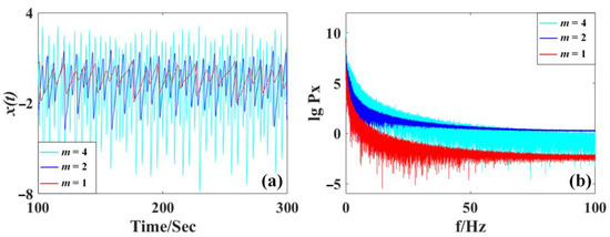
Figure 1.
Waveform and frequency spectra of x from the system (5) with a = 0.5, b = 0.6, c = 1.2 and initial values of (0, 1.3, 1): (a) chaotic signal x(t), (b) frequency spectra of the signal x(t).
By making a substitution in the system SL8II such a: x → px, y → py, z → pz, t → t/p, the system (3) becomes,
Let a = 0.5, b = 1.1, c = 1.2, and with initial values of (0, 1, 1), the chaotic signal of x, and the frequency spectrum are shown in Figure 2. Here we can see that the independent parameter p modifies the amplitude and frequency with inverse proportion. The larger p gets, the smaller and lower-frequency the signal. Therefore, the parameter p in the system (6) revises the amplitude of variables x, y, and z and frequency according to 1/p.
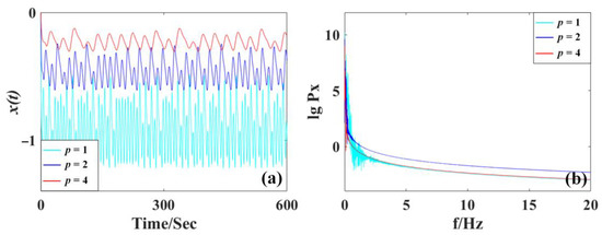
Figure 2.
Waveform and frequency spectra of x from the system (6) with a = 0.5, b = 1.1, c = 1.2 and initial values of (0, 1, 1): (a) chaotic signal x(t), (b) frequency spectra of the signal x(t).
Similarly, take a substitution in the system SL8III such as: x → nx, y → ny, z → nz, t → t/n, and let n3 = q, system (4) becomes,
Let a = 0.5, b = 0.6, c = 1.2, and with initial values of (0, 1, 0), the chaotic signal of x and the frequency spectrum are shown in Figure 3. Here we can see that the independent parameter q modifies the amplitude and frequency with inverse proportion. The larger q gets, the smaller and lower-frequency the signal. Therefore, the parameter q in the system (7) revises the amplitude of variables x, y, and z and frequency according to 1/.
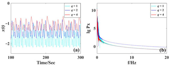
Figure 3.
Waveform and frequency spectra of x from the system (7) with a = 0.5, b = 0.6, c = 1.2 and initial values of (0, 1, 0): (a) chaotic signal x(t), (b) frequency spectra of the signal x(t).
Here two additional cases are derived, namely SL8II and SL8III, which show the different properties of amplitude/frequency control compared with SL8I. The independent parameter m, p, q modifies the amplitude and frequency with different scales, as shown in Figure 1, Figure 2 and Figure 3. Specifically, in Figure 1, the waveform of x(t) increases its oscillation when the parameter m increases from 1 to 4 with a wider band of the frequency spectrum. In Figure 2, the amplitude of waveform x(t) decreases when the parameter p increases from 1 to 4, and the corresponding frequency spectrum shrinks accordingly. In Figure 3, when the parameter q increases from 1 to 4, the oscillation of x(t) also decreases accordingly with the corresponding shrinking frequency spectrum.
As shown in Figure 4, when the parameter m varies in SL8I, all variables are revised in the positive direction. Larger m gives bigger and denser attractors, showing their power for amplitude/frequency control. However, in Figure 5 and Figure 6, the smaller parameter wins larger and denser attractors, showing their power of amplitude/frequency control. Note that, although all the parameters rescale the amplitude of x, y, and z, compared with the attractor of the system (5), it seems that the attractors of the system (6) and (7) show different offsets owing to the positive values of system variable y, which indicates that the effect of amplitude control can be easily demonstrated from the maximum value or average value of y.
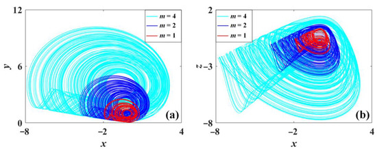
Figure 4.
Chaotic oscillation of system (5) with a = 0.5, b = 0.6, and c = 1.2 under initial condition (0, 1.3, 1): (a) x-y, (b) y-z. (m = 1 is red, m = 2 is blue, m = 4 is cyan.).
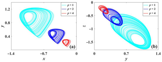
Figure 5.
Chaotic oscillation of system (6) with a = 0.5, b = 1.1, and c = 1.2 under initial condition (0, 1, 1): (a) x-y, (b) y-z. (p = 1 is cyan, p = 2 is blue, p = 4 is red.).
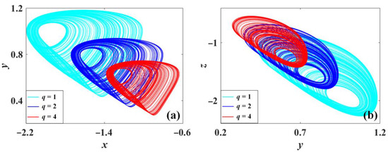
Figure 6.
Chaotic oscillation of system (7) with a = 0.5, b = 0.6, and c = 1.2 under initial condition (0, 1, 0): (a) x-y, (b) y-z. (q = 1 is cyan, q = 2 is blue, q = 4 is red.).
Further observation of the amplitude and frequency control can be proved from the evolution of the average value of the variable |x|, |y|, |z| and the Lyapunov exponents spectra. Here the average values of the absolute value of the system variables indicate the rescaled amplitude while the Lyapunov exponents reflect their frequency. As shown in Figure 7, the average absolute value of x, y, and z of the system (5) is scaled positively by m with increasing Lyapunov exponents, which means that the parameter m revises the amplitude and frequency simultaneously and positively in the system (5). However, the average values of x, y, and z of the system (6) and system (7) decrease with p and q with declined Lyapunov exponents, as shown in Figure 8 and Figure 9, where independent parameter q modifies the amplitude and frequency with inverse proportion.
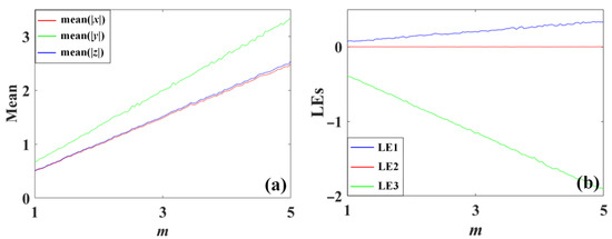
Figure 7.
Amplitude evolution of the system (5) with a = 0.5, b = 0.6, c = 1.2 under initial condition (0, 1.3, 1) when m varies in [1,4]: (a) average values, (b) Lyapunov exponents.
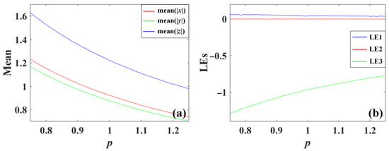
Figure 8.
System (6) with a = 0.5, b = 1.1, c = 1.2 under initial condition (0, 1, 1) when m varies in [0.75, 1.25]: (a) average values, (b) Lyapunov exponents.
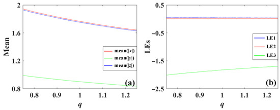
Figure 9.
System (7) with a = 0.5, b = 0.6, c = 1.2 under initial condition (0, 1, 0) when m varies in [0.75, 1.25]: (a) average values, (b) Lyapunov exponents.
4. Switchable Chaotic Circuit Structure and Circuit Simulation
In the following circuit design, a circuit framework is designed for realizing the state variables x(t), y(t), and z(t) in the chaotic system, which represent the voltages of capacitors [27,28,29,30,31]. The feedback terms are realized by integration, addition and inversion circuits based on the operational amplifiers. The voltage of the capacitor in the circuit corresponds to the state variables of x, y, and z in the system. Here the capacitors in the circuit are selected as C1= C2 = C3 = 10 nF with a synchronous time rescaling. When the system parameters are carefully checked, the resistors R1 and R6 are different for different systems. Here R6 is modified differently for realization of different system parameters, while R1 is used as a controlling knob for amplitude/frequency control, both of which can be realized with a rheostat.
The switches are applied for realization of different feedback of y, y3, and y5 associated with multipliers U4, U5, and U9, as shown in Figure 10. The output of y2 can be reused for feedback terms of y3 and y5 so that the multipliers can be saved further. The multiplier AD663AN is applied for the operation of multiplication and the operational amplifier LM741CH is selected for basic integral computing. The phase portraits from the circuit simulation are given in Figure 11, Figure 12 and Figure 13. The attractors in the plane of X-Y are of the same shape, as shown in Figure 4, Figure 5 and Figure 6. The switchable circuit for three cases is explained along with associated circuit equations as follows:
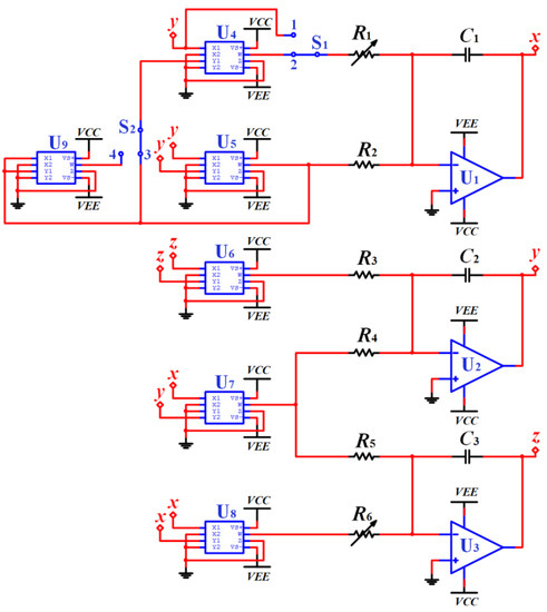
Figure 10.
Circuit schematic of SL8I, SL8II and SL8III.
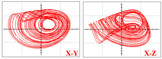
Figure 11.
Chaotic attractor in the system (8) from circuit simulation.
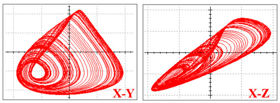
Figure 12.
Chaotic attractor in the system (9) from circuit simulation.
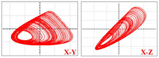
Figure 13.
Chaotic attractor in the system (10) from circuit simulation.
Case I: SL8I
Let the switch S1 connect to port 1 and switch S2 be off, then system (5) can be realized, in which case according to Kirchhoff’s law the circuit equation can be written as,
Here the parameters are set as C1 = C2 = C3 = 10 nF, R1 = 40 kΩ, R2 = 10 kΩ, R3 = 20 kΩ, R4 = 10 kΩ, R5 = 8.3 kΩ, R6 = 16.6 kΩ, Vcc = 15 V, Vee = 15 V for the chaotic oscillation with the phase portrait, as shown in Figure 11.
Case II: SL8II
Let switch S1 connect to port 2 and switch S2 connect to port 3, then system (6) is realized with the circuit equation,
Here the parameters are set as follows: C1 = C2 = C3 = 10 nF, R1 = 4 kΩ, R2 = 10 kΩ, R3 = 20 kΩ, R4 = 10 kΩ, R5 = 8.3 kΩ, R6 = 9 kΩ, Vcc = 15 V, Vee = 15 V, corresponding phase portrait are as shown in Figure 12.
Case III: SL8III
Let the switch S1 points connect to port 2 and the switch S2 points connect to port 4, then system (6) is implemented and the system equation can be further expressed as,
Here the parameters are set as follows: C1 = C2 = C3 = 10 nF, R1 = 400 Ω, R2 = 10 kΩ, R3 = 20 kΩ, R4 = 10 kΩ, R5 = 8.3 kΩ, R6 = 16.6 kΩ, Vcc = 15 V, Vee = 15 V, corresponding phase portrait are as shown in Figure 13.
5. Conclusions
In this paper, a chaotic system containing a non-quadratic term is chosen for realizing multiscale amplitude/frequency control. By revising the linear term with higher cubic and quintic terms, two extra systems are derived for amplitude/frequency scaling. Different feedback draws different directions for amplitude/frequency control with multiscale. The coefficient of a linear term revises the amplitude/frequency positively while the coefficient of cubic and quintic terms changes the corresponding oscillation in a reverse direction. In this circuit structure, six multipliers, three operational amplifiers, three capacitors, six resistors, and two three-way switches are utilized for the implementation of three chaotic systems with fifteen quadratic terms. A switchable circuit is designed in a compact structure giving multiscale amplitude/frequency control and showing higher reliability. The features of amplitude and frequency control characteristics can be applied in the field of radar communication as well as image encryption or, furthermore, in a mechanical system.
Author Contributions
Writing—original, Z.S.; Methodology, Z.S. and L.C.; Writing—review & editing, C.L.; Formal analysis, Y.G. and Z.L.; Resources, Y.G. and Z.L.; Validation, L.C. All authors have read and agreed to the published version of the manuscript.
Funding
This research was funded by the National Natural Science Foundation of China (Grant No.: 61871230), and a Project Funded by the Priority Academic Program Development of Jiangsu Higher Education Institutions.
Institutional Review Board Statement
This study was approved.
Informed Consent Statement
Consent was obtained from all the authors involved in the study. All authors read and approved the final manuscript.
Data Availability Statement
The data that support the findings of this study are available from the corresponding author upon reasonable request.
Acknowledgments
The authors are thankful to the anonymous reviewers for their careful reading, and constructive suggestions for the improvement of this research work.
Conflicts of Interest
The authors declare that they have no known competing financial interests or personal relationships that could have appeared to influence the work reported in this paper.
References
- Liu, X.; Tong, X.; Wang, Z.; Zhang, M. A new n-dimensional conservative chaos based on Generalized Hamiltonian System and its’ applications in image encryption. Chaos Solitons Fractals 2022, 154, 111693. [Google Scholar] [CrossRef]
- Deng, J.; Zhou, M.; Wang, C.; Wang, S.; Xu, C. Image segmentation encryption algorithm with chaotic sequence generation participated by cipher and multi-feedback loops. Multimed. Tools Appl. 2021, 80, 13821–13840. [Google Scholar] [CrossRef]
- Liu, S.; Li, Y.; Ge, X.; Li, C.; Zhao, Y. A novel hyperchaotic map and its application in fast video encryption. Phys. Scr. 2022, 97, 085210. [Google Scholar] [CrossRef]
- Liu, L.; Wei, Z.X.; Xiang, H. A novel image encryption algorithm based on compound-coupled logistic chaotic map. Multimed. Tools Appl. 2022, 81, 19999–20019. [Google Scholar] [CrossRef]
- Rong, K.; Bao, H.; Li, H.; Hua, Z.; Bao, B. Memristive Henon map with hidden Neimark–Sacker bifurcations. Nonlinear Dyn. 2022, 108, 4459–4470. [Google Scholar] [CrossRef]
- Bao, H.; Gu, Y.; Sun, J.; Zhang, X.; Bao, B. Memristor-based Gauss chaotic maps with hidden/self-exited dynamics. J. Differ. Equ. Appl. 2022, 1–17. [Google Scholar] [CrossRef]
- Lin, H.; Wang, C.; Cui, L.; Sun, Y.; Xu, C.; Yu, F. Brain-like initial-boosted hyperchaos and application in biomedical image encryption. IEEE Trans. Ind. Inform. 2022, 18, 8839–8850. [Google Scholar] [CrossRef]
- Lin, H.; Wang, C.; Xu, C.; Zhang, X.; Iu, H.H. A memristive synapse control method to generate diversified multi-structure chaotic attractors. IEEE Trans. Comput. Aided Des. Integr. Circuits Syst. 2022. [Google Scholar] [CrossRef]
- Lin, H.; Wang, C.; Sun, Y.; Wang, T. Generating-Scroll Chaotic Attractors From a Memristor-Based Magnetized Hopfield Neural Network. IEEE Trans. Circuits Syst. II Express Briefs 2022, 70, 311–315. [Google Scholar] [CrossRef]
- Ma, T.; Mou, J.; Yan, H.; Cao, Y. A new class of Hopfield neural network with double memristive synapses and its DSP implementation. Eur. Phys. J. Plus 2022, 137, 1135. [Google Scholar] [CrossRef]
- Zhang, X.; Liu, J.; Wang, D.; Liu, H. Geometric control and synchronization of a complex-valued laser chain network. Nonlinear Dyn. 2022, 1–16. [Google Scholar] [CrossRef]
- Liang, J.; Liu, J.; Chen, G. Observer-based synchronization of time-delay complex-variable chaotic systems with complex parameters. Fractals 2022, 30, 2250197. [Google Scholar] [CrossRef]
- Lai, Q.; Zhang, H.; Kuate, P.D.K.; Xu, G.; Zhao, X.W. Analysis and implementation of no-equilibrium chaotic system with applicationb in image encryption. Appl. Intell. 2022, 52, 11448–11471. [Google Scholar] [CrossRef]
- Li, C.; Lei, T.; Liu, Z. Offset parameter cancellation produces countless coexisting attractors. Chaos 2022, 32, 121104. [Google Scholar] [CrossRef] [PubMed]
- Dmitriev, A.S.; Kletsov, A.V.; Laktyushkin, A.M.; Panas, A.I.; Starkov, S.O. Ultrawideband wireless communications based on dynamic chaos. J. Commun. Technol. Electron. 2006, 51, 1126–1140. [Google Scholar] [CrossRef]
- Lin, F.Y.; Chao, Y.K.; Wu, T.C. Effective bandwidths of broadband chaotic signals. IEEE J. Quantum Electron. 2012, 48, 1010–1014. [Google Scholar] [CrossRef]
- Deng, T.; Xia, G.Q.; Wu, Z.M. Broadband chaos synchronization and communication based on mutually coupled VCSELs subject to a bandwidth-enhanced chaotic signal injection. Nonlinear Dyn. 2014, 76, 399–407. [Google Scholar] [CrossRef]
- Bao, H.; Liu, W.; Ma, J.; Wu, H. Memristor initial-offset boosting in memristive HR neuron model with hidden firing patterns. Int. J. Bifurc. Chaos 2020, 30, 2030029. [Google Scholar] [CrossRef]
- Li, C.; Sprott, J.C. Amplitude control approach for chaotic signals. Nonlinear Dyn. 2013, 73, 1335–1341. [Google Scholar] [CrossRef]
- Li, C.; Hu, W.; Sprott, J.C.; Wang, X. Multistability in symmetric chaotic systems. Eur. Phys. J. Spec. Top. 2015, 224, 1493–1506. [Google Scholar] [CrossRef]
- Li, C.; Sprott, J.C. Variable-boostable chaotic flows. Optik 2016, 127, 10389–10398. [Google Scholar] [CrossRef]
- Jiang, Y.; Li, C.; Zhang, C.; Zhao, Y.; Zang, H. A Double-Memristor Hyperchaotic Oscillator with Complete Amplitude Control. IEEE Trans. Circuits Syst. I Regul. Pap. 2021, 68, 4935–4944. [Google Scholar] [CrossRef]
- Li, Y.; Li, C.; Zhang, S.; Chen, G.; Zeng, Z. A Self-reproduction hyperchaotic map with compound lattice dynamics. IEEE Trans. Ind. Electron. 2022, 69, 10564–10572. [Google Scholar] [CrossRef]
- Wu, J.; Li, C.; Ma, X.; Lei, T.; Chen, G. Simplification of chaotic circuits with quadratic nonlinearity. IEEE Trans. Circuits Syst. II Express Briefs 2021, 69, 1837–1841. [Google Scholar] [CrossRef]
- Li, C.; Sprott, J.C.; Zhang, X.; Chai, L.; Liu, Z. Constructing conditional symmetry in symmetric chaotic systems. Chaos Solitons Fractals 2022, 155, 111723. [Google Scholar] [CrossRef]
- Li, C.; Sprott, J.C. Chaotic flows with a single nonquadratic term. Phys. Lett. A 2014, 378, 178–183. [Google Scholar] [CrossRef]
- Yao, Y.; Ma, J. Logical stochastic and vibrational resonances induced by periodic force in the FitzHugh–Nagumo neuron. Eur. Phys. J. Plus 2022, 137, 1214. [Google Scholar] [CrossRef]
- Wen, Z.; Wang, C.; Deng, Q.; Lin, H. Regulating memristive neuronal dynamical properties via excitatory or inhibitory magnetic field coupling. Nonlinear Dyn. 2022, 110, 3823–3835. [Google Scholar] [CrossRef]
- Bao, B.; Hu, J.; Cai, J.; Zhang, X.; Bao, H. Memristor-induced mode transitions and extreme multistability in a map-based neuron model. Nonlinear Dyn. 2022, 111, 3765–3779. [Google Scholar] [CrossRef]
- Min, F.; Rui, Z. Boundary dynamics of a non-smooth memristive Hindmarsh–Rose neuron system. Chaos Interdiscip. J. Nonlinear Sci. 2022, 32, 103117. [Google Scholar] [CrossRef]
- Chen, C.; Min, F. ReLU-type memristor-based Hopfield neural network. Eur. Phys. J. Spec. Top. 2022, 231, 2979–2992. [Google Scholar] [CrossRef]
Disclaimer/Publisher’s Note: The statements, opinions and data contained in all publications are solely those of the individual author(s) and contributor(s) and not of MDPI and/or the editor(s). MDPI and/or the editor(s) disclaim responsibility for any injury to people or property resulting from any ideas, methods, instructions or products referred to in the content. |
© 2023 by the authors. Licensee MDPI, Basel, Switzerland. This article is an open access article distributed under the terms and conditions of the Creative Commons Attribution (CC BY) license (https://creativecommons.org/licenses/by/4.0/).