


Working Performance Improvement of a Novel Independent Metering Valve System by Using a Neural Network-Fractional Order-Proportional-Integral-Derivative Controller


Abstract
:1. Introduction
- For the first time, the NNFOPID controller was applied to a real test rig that mimics the motion of the boom cylinder of a hydraulic excavator. The advantage of this controller was used for the system without identifying the model of the system (model-free), resulting in minimizing the amount of computing and hardware of the controller on the NIMV system.
- The tuning method of five parameters based on the neural network algorithm was applied to the FOPID controller to enhance the tracking precision and energy saving.
- Both co-simulation and experimental platforms were employed to validate the effectiveness of the proposed controller.
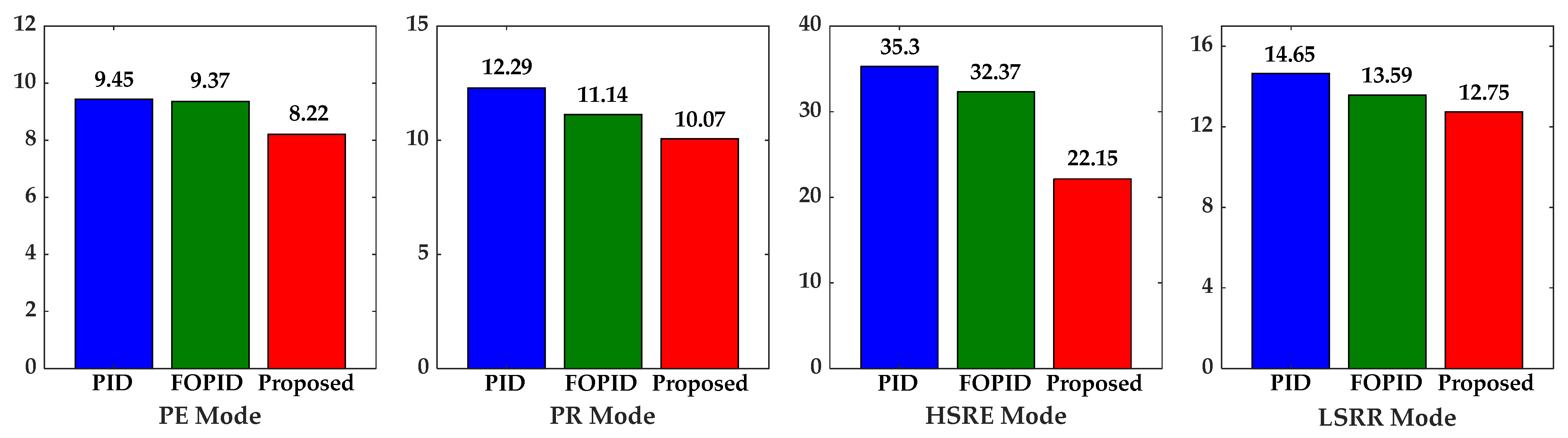
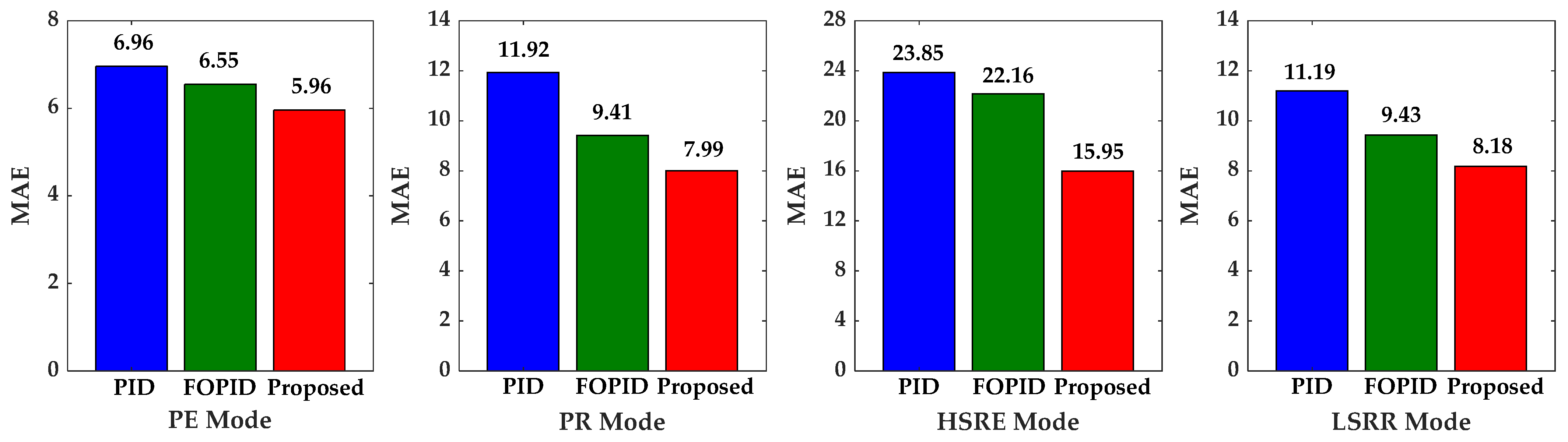
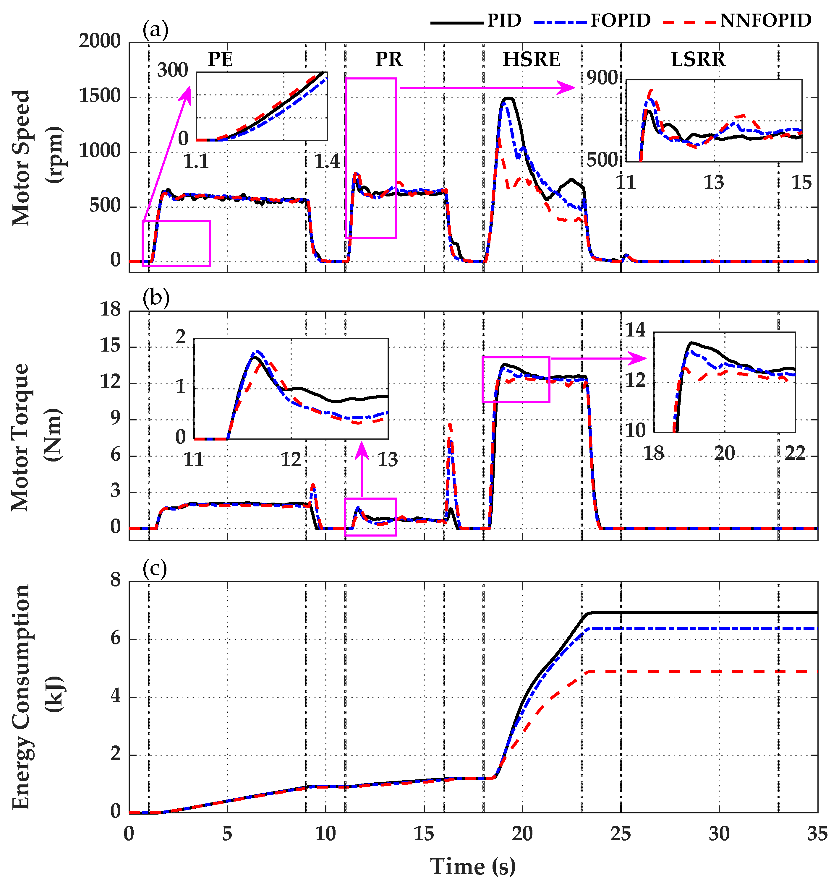
- Compared with the PID and FOPID controllers, the proposed controller not only achieved high tracking precision but also used less energy consumption, saving up to 23.33% and 29.25% under experimental conditions, respectively.
2. System Description
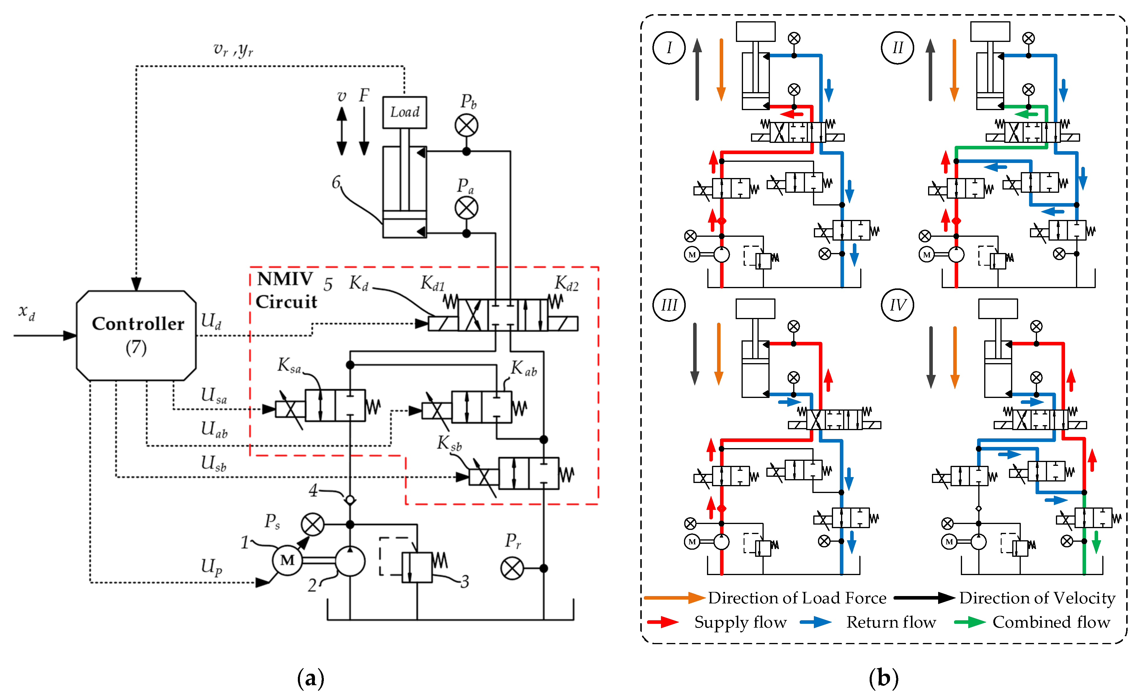
2.1. The Novel Independent Metering Valve System
2.2. Analysis of Energy Consumption of the System
3. Control Algorithm
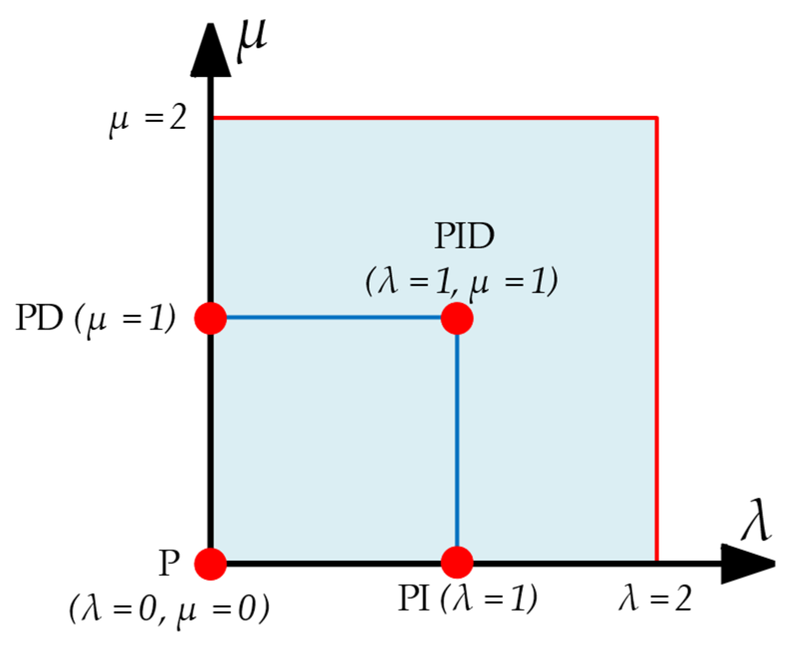
3.1. Fractional Order PID
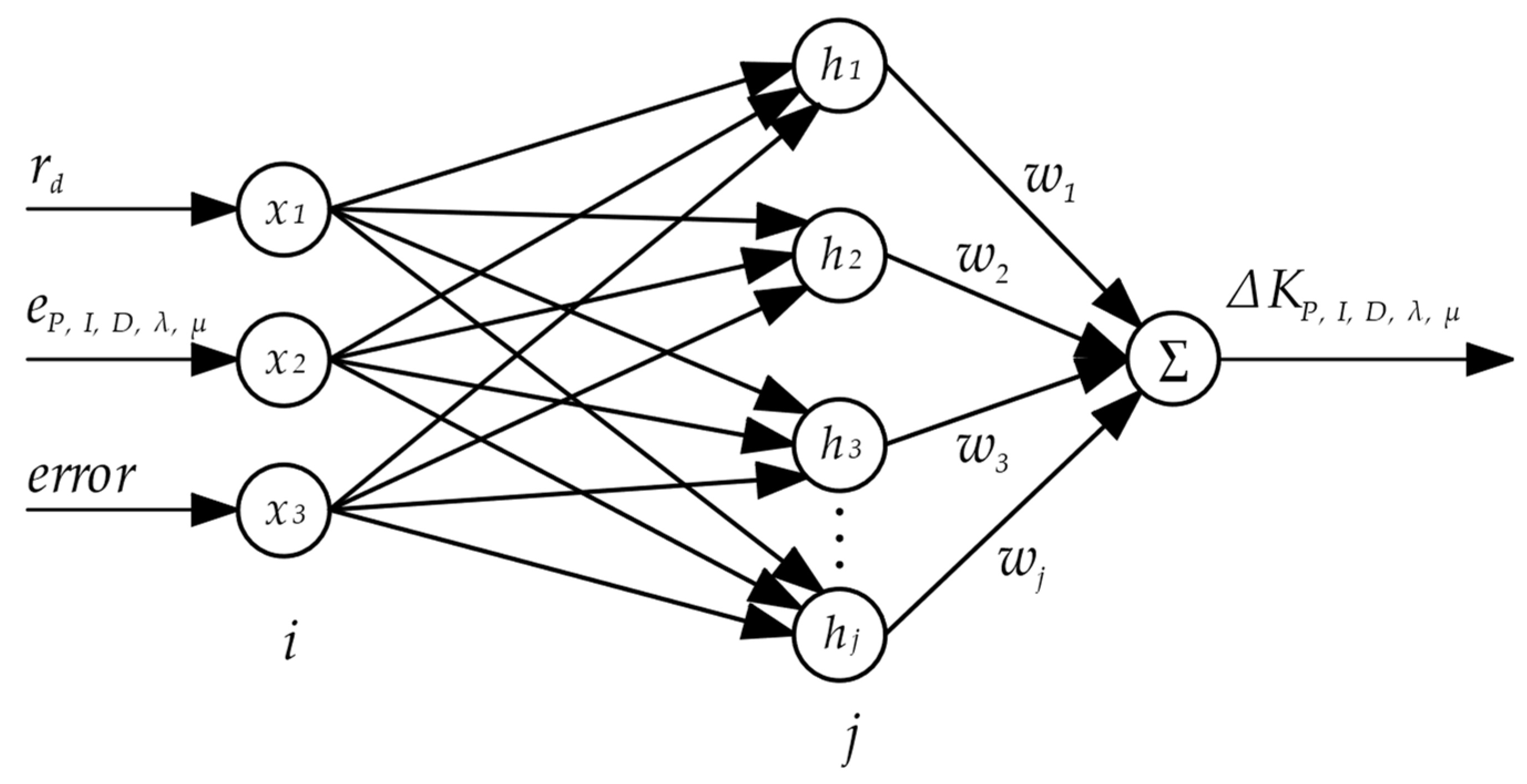
3.2. Neural Network FOPID Controller Design
4. Simulation and Experiment Results
4.1. Simulation Study
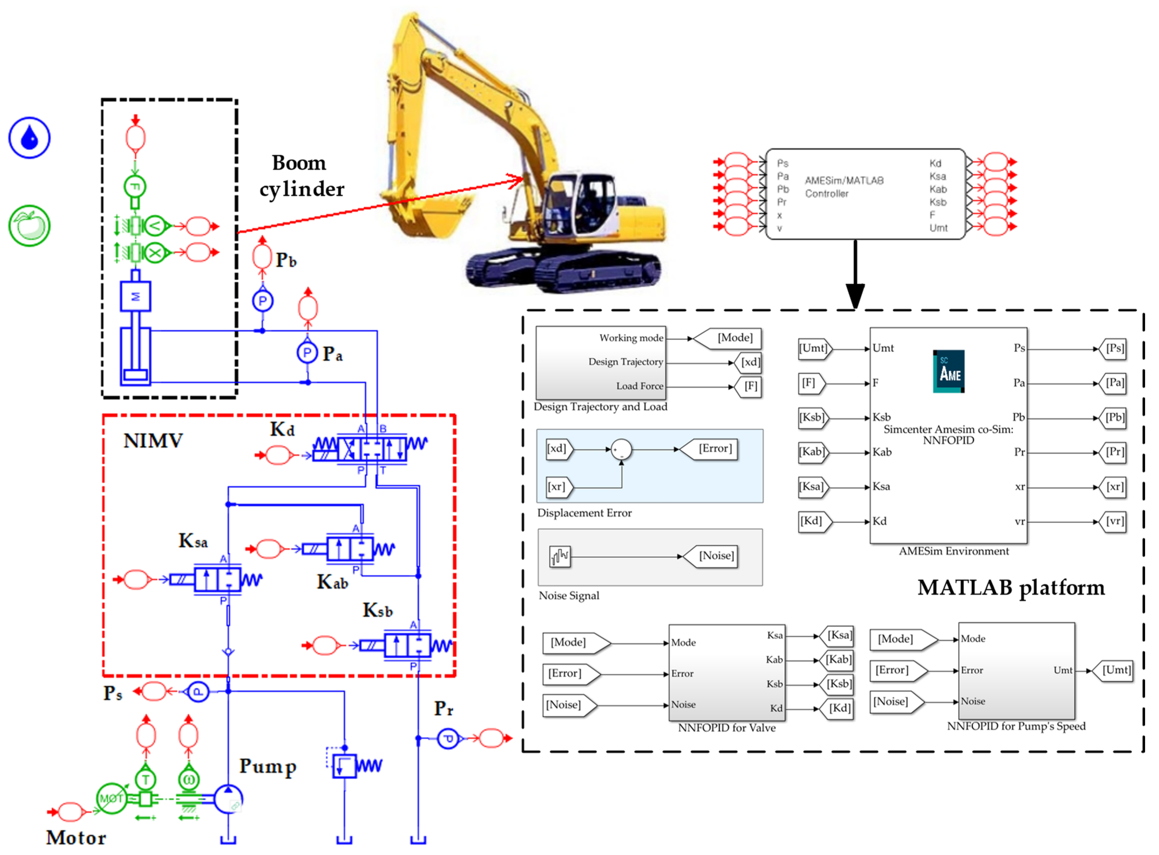
4.1.1. Simulation Model
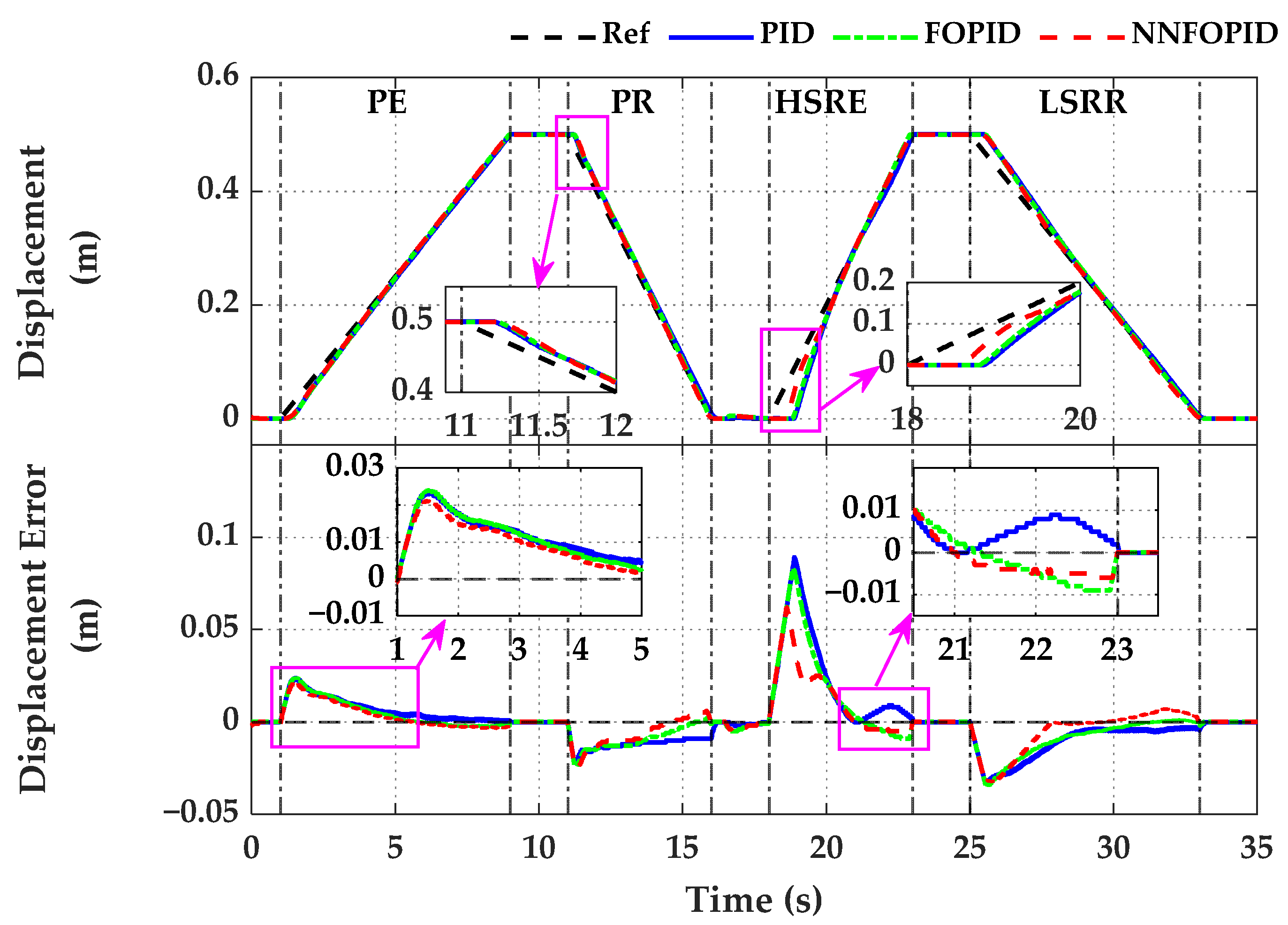
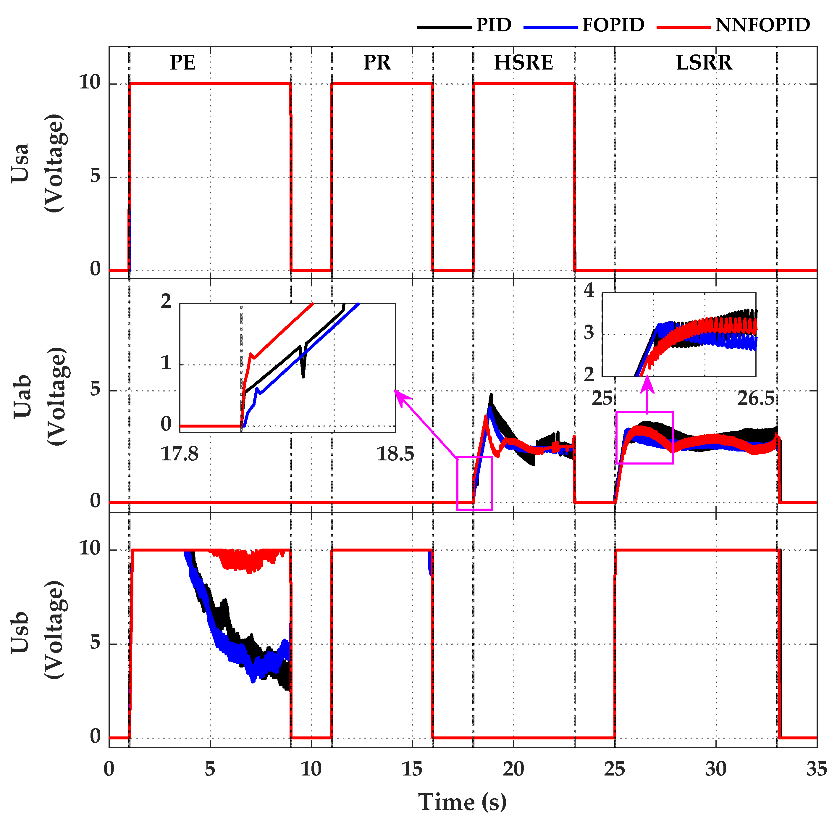
4.1.2. Simulation Result
4.2. Experiment Verification
4.2.1. Experiment Setup
4.2.2. Experimental Results
5. Conclusions
Author Contributions
Funding
Data Availability Statement
Conflicts of Interest
References
- Li, Z.; Wang, C.; Quan, L.; Hao, Y.; Ge, L.; Xia, L. Study on energy efficiency characteristics of the heavy-duty manipulator driven by electro-hydraulic hybrid active-passive system. Autom. Constr. 2021, 125, 103646. [Google Scholar] [CrossRef]
- Yang, J.; Liu, B.; Zhang, T.; Hong, J.; Zhang, H. Application of energy conversion and integration technologies based on electro-hydraulic hybrid power systems: A review. Energy Convers. Manag. 2022, 272, 116372. [Google Scholar] [CrossRef]
- Xu, B.; Cheng, M. Motion control of multi-actuator hydraulic systems for mobile machineries: Recent advancements and future trends. Front. Mech. Eng. 2018, 13, 151–166. [Google Scholar] [CrossRef]
- Yang, C.; Zhou, L.; Wang, J.; Xu, T.; Yang, C.; Ye, G. Research on energy saving system of hydraulic excavator based on three-chamber accumulator. J. Energy Storage 2023, 72, 108571. [Google Scholar] [CrossRef]
- Qin, T.; Li, Y.; Quan, L.; Yang, L. An Adaptive Robust Impedance Control Considering Energy-Saving of Hydraulic Excavator Boom and Stick Systems. IEEE/ASME Trans. Mechatron. 2022, 27, 1928–1936. [Google Scholar] [CrossRef]
- Wu, B.; Wang, W.; Yao, Z.; Xuan, K.; Wu, Z.; Shen, X.; Li, X.; Zhang, H.; Xue, Y.; Cao, X.; et al. Multi-pollutant emission characteristics of non-road construction equipment based on real-world measurement. Sci. Total Environ. 2022, 853, 158601. [Google Scholar] [CrossRef]
- Liu, H.; Zhao, Q. Review on Energy Conservation of Construction Machinery for Pumping Concrete. Processes 2023, 11, 842. [Google Scholar] [CrossRef]
- Yi, H.-S.; Cha, S. Optimal Energy Management of the Electric Excavator Using Super Capacitor. Int. J. Precis. Eng. Manuf.-Green Technol. 2021, 8, 151–164. [Google Scholar] [CrossRef]
- Lin, T.; Chen, Q.; Ren, H.; Huang, W.; Chen, Q.; Fu, S. Review of boom potential energy regeneration technology for hydraulic construction machinery. Renew. Sustain. Energy Rev. 2017, 79, 358–371. [Google Scholar] [CrossRef]
- Chen, M.; Zhao, D. The gravitational potential energy regeneration system with closed-circuit of boom of hydraulic excavator. Mech. Syst. Signal Process. 2017, 82, 178–192. [Google Scholar] [CrossRef]
- Mahato, A.C.; Ghoshal, S.K. Energy-saving strategies on power hydraulic system: An overview. Proc. Inst. Mech. Eng. Part I J. Syst. Control Eng. 2020, 235, 147–169. [Google Scholar] [CrossRef]
- He, X.; Xiao, G.; Hu, B.; Tan, L.; Tang, H.; He, S.; He, Z. The applications of energy regeneration and conversion technologies based on hydraulic transmission systems: A review. Energy Convers. Manag. 2020, 205, 112413. [Google Scholar] [CrossRef]
- Li, J.; Zhao, J. Energy recovery for hybrid hydraulic excavators: Flywheel-based solutions. Autom. Constr. 2021, 125, 103648. [Google Scholar] [CrossRef]
- Li, J.; Zhao, J.; Zhang, X. A Novel Energy Recovery System Integrating Flywheel and Flow Regeneration for a Hydraulic Excavator Boom System. Energies 2020, 13, 315. [Google Scholar] [CrossRef]
- Do, T.C.; Dinh, T.Q.; Yu, Y.; Ahn, K.K. Innovative powertrain and advanced energy management strategy for hybrid hydraulic excavators. Energy 2023, 282, 128951. [Google Scholar] [CrossRef]
- Chen, Q.; Lin, T.; Ren, H.; Fu, S. Novel potential energy regeneration systems for hybrid hydraulic excavators. Math. Comput. Simul. 2019, 163, 130–145. [Google Scholar] [CrossRef]
- Gong, J.; Zhang, D.; Liu, C.; Zhao, Y.; Hu, P.; Quan, W. Optimization of electro-hydraulic energy-savings in mobile machinery. Autom. Constr. 2019, 98, 132–145. [Google Scholar] [CrossRef]
- Tan, L.; He, X.; Xiao, G.; Jiang, M.; Yuan, Y. Design and energy analysis of novel hydraulic regenerative potential energy systems. Energy 2022, 249, 123780. [Google Scholar] [CrossRef]
- Jung, T.; Raduenz, H.; Krus, P.J.; De Negri, V.; Lee, J. Boom energy recuperation system and control strategy for hydraulic hybrid excavators. Autom. Constr. 2022, 135, 104046. [Google Scholar] [CrossRef]
- Liu, J.; Jiao, Z.; Xian, F.; Liu, W. Energy recovery and utilization system of excavator boom based on flow regeneration and balance theory. J. Braz. Soc. Mech. Sci. Eng. 2019, 42, 35. [Google Scholar] [CrossRef]
- Tong, Z.-M.; Wu, S.-S.; Tong, S.-G.; Yue, Y.-Q.; Li, Y.-S.; Xu, Z.-Y.; Zhong, Y.-W. Energy-saving technologies for construction machinery: A review of electro-hydraulic pump-valve coordinated system. J. Zhejiang Univ.-Sci. A 2020, 21, 331–349. [Google Scholar] [CrossRef]
- Zhong, Q.; Bao, H.; Li, Y.; Hong, H.; Zhang, B.; Yang, H. Investigation into the Independent Metering Control Performance of a Twin Spools Valve with Switching Technology-controlled Pilot Stage. Chin. J. Mech. Eng. 2021, 34, 91. [Google Scholar] [CrossRef]
- Hu, S.; Wang, L.; Li, Y.; Zhang, L. Variable Universe Fuzzy Controller for an Independent Metering System of Construction Machinery. Processes 2023, 11, 901. [Google Scholar] [CrossRef]
- Weber, J. Independent metering systems. Int. J. Hydromechatron. 2018, 1, 91–106. [Google Scholar] [CrossRef]
- Choi, K.; Seo, J.; Nam, Y.; Kim, K.U. Energy-saving in excavators with application of independent metering valve. J. Mech. Sci. Technol. 2015, 29, 387–395. [Google Scholar] [CrossRef]
- Abuowda, K.; Okhotnikov, I.; Noroozi, S.; Godfrey, P.; Dupac, M. A review of electrohydraulic independent metering technology. ISA Trans. 2019, 98, 364–381. [Google Scholar] [CrossRef]
- Lyu, L.; Chen, Z.; Yao, B. Development of parallel-connected pump–valve-coordinated control unit with improved performance and efficiency. Mechatronics 2020, 70, 102419. [Google Scholar] [CrossRef]
- Lyu, L.; Chen, Z.; Yao, B. Energy Saving Motion Control of Independent Metering Valves and Pump Combined Hydraulic System. IEEE/ASME Trans. Mechatron. 2019, 24, 1909–1920. [Google Scholar] [CrossRef]
- Lyu, L.; Chen, Z.; Yao, B. Development of Pump and Valves Combined Hydraulic System for Both High Tracking Precision and High Energy Efficiency. IEEE Trans. Ind. Electron. 2019, 66, 7189–7198. [Google Scholar] [CrossRef]
- Li, C.; Lyu, L.; Helian, B.; Chen, Z.; Yao, B. Precision Motion Control of an Independent Metering Hydraulic System with Nonlinear Flow Modeling and Compensation. IEEE Trans. Ind. Electron. 2022, 69, 7088–7098. [Google Scholar] [CrossRef]
- Ding, R.; Zhang, J.; Xu, B. Advanced Energy Management of a Novel Independent Metering Meter-Out Control System: A Case Study of an Excavator. IEEE Access 2018, 6, 45782–45795. [Google Scholar] [CrossRef]
- Shi, J.; Quan, L.; Zhang, X.; Xiong, X. Electro-hydraulic velocity and position control based on independent metering valve control in mobile construction equipment. Autom. Constr. 2018, 94, 73–84. [Google Scholar] [CrossRef]
- Phan, V.D.; Ahn, K.K. Fault-tolerant control for an electro-hydraulic servo system with sensor fault compensation and disturbance rejection. Nonlinear Dyn. 2023, 111, 10131–10146. [Google Scholar] [CrossRef]
- Nguyen, M.H.; Ahn, K.K. Output Feedback Robust Tracking Control for a Variable-Speed Pump-Controlled Hydraulic System Subject to Mismatched Uncertainties. Mathematics 2023, 11, 1783. [Google Scholar] [CrossRef]
- Borase, R.P.; Maghade, D.K.; Sondkar, S.Y.; Pawar, S.N. A review of PID control, tuning methods and applications. Int. J. Dyn. Control 2021, 9, 818–827. [Google Scholar] [CrossRef]
- Wrat, G.; Bhola, M.; Ranjan, P.; Mishra, S.K.; Das, J. Energy saving and Fuzzy-PID position control of electro-hydraulic system by leakage compensation through proportional flow control valve. ISA Trans. 2020, 101, 269–280. [Google Scholar] [CrossRef]
- Tepljakov, A.; Alagoz, B.B.; Yeroglu, C.; Gonzalez, E.A.; Hosseinnia, S.H.; Petlenkov, E.; Ates, A.; Cech, M. Towards Industrialization of FOPID Controllers: A Survey on Milestones of Fractional-Order Control and Pathways for Future Developments. IEEE Access 2021, 9, 21016–21042. [Google Scholar] [CrossRef]
- Maddahi, A.; Sepehri, N.; Kinsner, W. Fractional-Order Control of Hydraulically Powered Actuators: Controller Design and Experimental Validation. IEEE/ASME Trans. Mechatron. 2019, 24, 796–807. [Google Scholar] [CrossRef]
- Edet, E.; Katebi, R. On Fractional-order PID Controllers. IFAC-Pap. 2018, 51, 739–744. [Google Scholar] [CrossRef]
- Tepljakov, A.; Alagoz, B.B.; Yeroglu, C.; Gonzalez, E.; HosseinNia, S.H.; Petlenkov, E. FOPID Controllers and Their Industrial Applications: A Survey of Recent Results. IFAC-Pap. 2018, 51, 25–30. [Google Scholar] [CrossRef]
- Essa, M.E.-S.M.; Aboelela, M.A.S.; Hassan, M.A.M. Application of Fractional Order Controllers on Experimental and Simulation Model of Hydraulic Servo System. In Fractional Order Control and Synchronization of Chaotic Systems; Azar, A.T., Vaidyanathan, S., Ouannas, A., Eds.; Springer International Publishing: Cham, Switzerland, 2017; pp. 277–324. [Google Scholar]
- Bingi, K.; Ibrahim, R.; Karsiti, M.N.; Hassan, S.M.; Harindran, V.R. Fractional-Order Systems and PID Controllers; Springer: Berlin/Heidelberg, Germany, 2020; Volume 264. [Google Scholar]
- Do, T.C.; Tran, D.T.; Dinh, T.Q.; Ahn, K.K. Tracking Control for an Electro-Hydraulic Rotary Actuator Using Fractional Order Fuzzy PID Controller. Electronics 2020, 9, 926. [Google Scholar] [CrossRef]
- Jiangbo, Z.; Junzheng, W. The fractional order PI control for an energy saving electro-hydraulic system. Trans. Inst. Meas. Control 2015, 39, 505–519. [Google Scholar] [CrossRef]
- Nguyen, T.-H.; Do, T.-C.; Ahn, K.-K. A Study on a New Independent Metering Valve for Hydraulic Boom Excavator. Appl. Sci. 2022, 12, 605. [Google Scholar] [CrossRef]
- Nguyen, T.H.; Do, T.C.; Nguyen, V.H.; Ahn, K.K. High Tracking Control for a New Independent Metering Valve System Using Velocity-Load Feedforward and Position Feedback Methods. Appl. Sci. 2022, 12, 9827. [Google Scholar] [CrossRef]
- Bao, H.; He, D.; Zhang, B.; Zhong, Q.; Hong, H.; Yang, H. Research on Dynamic Performance of Independent Metering Valves Controlling Concrete-Placing Booms Based on Fuzzy-LADRC Controller. Actuators 2023, 12, 139. [Google Scholar] [CrossRef]
- Zhang, X.; Qiao, S.; Quan, L.; Ge, L. Velocity and Position Hybrid Control for Excavator Boom Based on Independent Metering System. IEEE Access 2019, 7, 71999–72011. [Google Scholar] [CrossRef]
- Jun, G.; Daqing, Z.; Yong, G.; Zhongyong, T.; Changsheng, L.; Peng, H.; Yuming, Z.; Weicai, Q.; Yongping, J. Potential energy recovery method based on alternate recovery and utilization of multiple hydraulic cylinders. Autom. Constr. 2020, 112, 103105. [Google Scholar] [CrossRef]
- Tepljakov, A.; Petlenkov, E.; Belikov, J. FOMCOM: A MATLAB toolbox for fractional-order system identification and control. Int. J. Microelectron. Comput. Sci. 2011, 2, 51–62. [Google Scholar]
- Liu, J. Radial Basis Function (RBF) Neural Network Control for Mechanical Systems: Design, Analysis and Matlab Simulation; Springer Science & Business Media: Berlin/Heidelberg, Germany, 2013. [Google Scholar]


| Description | Remark and Unit | Value |
|---|---|---|
| Boom cylinder | Model | D140H-LA40B-N500 |
| Stroke length (mm) | 500 | |
| Piston diameter (mm) | 40 | |
| Rod diameter (mm) | 20 | |
| Hydraulic pump | Type | Gear Pump SAP20-8.0 |
| Displacement (cc/rev) | 8.3 | |
| Max. speed control (rpm) | 1500 | |
| Volumetric efficiency * | 0.9 | |
| Torque efficiency * | 0.95 | |
| Proportional valve | Type | EHPV SP10-24 |
| Max. flow (L/min) | 26.5 | |
| Max. pressure (bar) | 207 | |
| Pressure drops (bar) * | 10 | |
| Directional control valve | Model | RPE3-063Z11/24V |
| Max. flow (L/min) | 80 | |
| Max. pressure (bar) | 350 | |
| Pressure drops (bar) * | 10 | |
| Relief valve | Model | VPN1-06-MP-32S |
| Cracking pressure (bar) | 100 | |
| Max. flow (L/min) | 70 | |
| Max. pressure (bar) | 320 | |
| Load | (kg) | 100 |
| Working Mode | Ksa | Kab | Ksb | Kd | Time |
|---|---|---|---|---|---|
| PE | Fully open | Closed | Control | Kd2 | 1 to 9 |
| PR | Fully open | Closed | Control | Kd1 | 11 to 16 |
| HSRE | Fully open | Control | Closed | Kd2 | 18 to 23 |
| LSRR | Closed | Control | Fully open | Kd2 | 25 to 33 |
| Component | Mode | |||||
|---|---|---|---|---|---|---|
| Valve | PE | 1 | 1 | 0.1 | 0.3 | 0.6 |
| PR | −2 | −0.5 | −0.01 | 0.3 | 0.6 | |
| HSRE | 0.05 | 0.01 | 0.001 | 1.5 | 0.5 | |
| LSRR | −1.5 | −0.1 | −0.01 | 0.8 | 1.05 | |
| Pump | PE | 60 | 15 | 1 | 1.2 | 0.6 |
| PR | −35 | −5 | −1 | 1.5 | 1.2 | |
| HSRE | 20 | 5 | 1 | 0.5 | 0.5 |
| Description | Remark and Unit | Value |
|---|---|---|
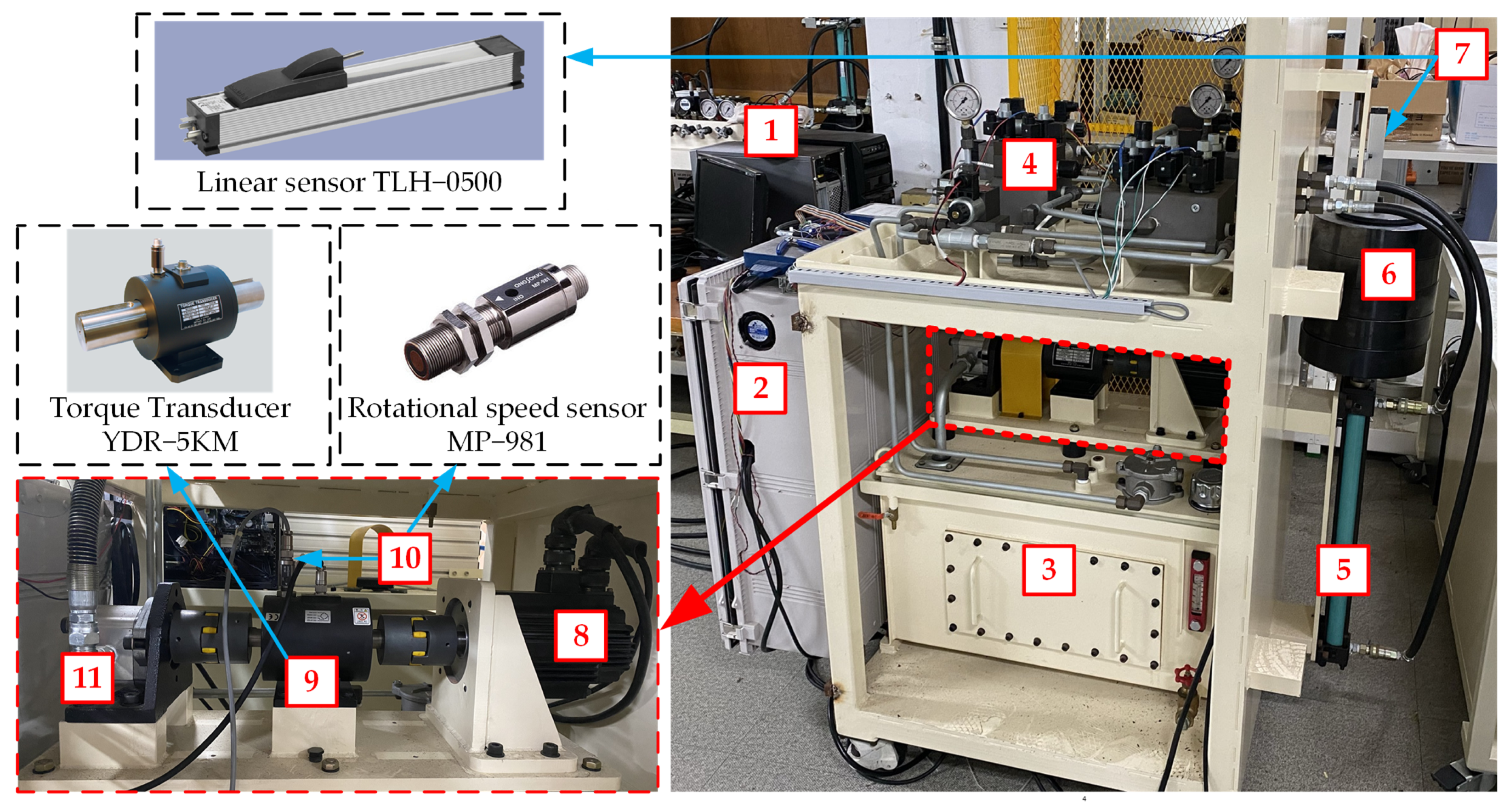
| Linear sensor | Model | TLH−0500 |
| Linearity (±) | 0.05% | |
| Amplifiers for EHPV | Mode | KURP−9502 |
| Power supply (VDC) | 24 | |
| Input range (VDC) | 0 to 10 | |
| Output range (VDC) | 0 to 24 | |
| Pressure sensor | Model | PMCE0200BDAA |
| Pressure range (bar) | 0 to 200 | |
| Power supply (VDC) | 24 | |
| Output range (VDC) | 0 to 5 | |
| Torque transducer | Model | YDR−5KM |
| Capacity (Nm) | 49.03 | |
| Rotational speed sensor | Model | MP-981 |
| Power supply (VDC) | 12 | |
| Output waveform (V) | 5 ± 0.5 or less | |
| Servo motor | Model | FMACN22−AB00 |
| Power (kW) | 2.2 | |
| PCI card 1 | Type | NI PCI−6221 |
| Resolution | 16AI/2AO: 16 bits | |
| PCI card 2 | Type | NI PCI−6703 |
| Resolution | 16AO: 16 bits |
| Component | Mode | |||||
|---|---|---|---|---|---|---|
| Valve | PE | 1 | 0.05 | 0.005 | 1.55 | 0.1 |
| PR | −5 | −1 | −0.01 | 0.6 | 0.5 | |
| HSRE | 0.04 | 0.02 | 0.005 | 1.25 | 0.8 | |
| LSRR | −0.08 | −0.03 | −0.005 | 1.1 | 0.9 | |
| Pump | PE | 25 | 10 | 1 | 1.2 | 0.4 |
| PR | −40 | −5 | −1 | 2 | 1.2 | |
| HSRE | 20 | 5 | 1 | 1.2 | 1.5 |
Disclaimer/Publisher’s Note: The statements, opinions and data contained in all publications are solely those of the individual author(s) and contributor(s) and not of MDPI and/or the editor(s). MDPI and/or the editor(s) disclaim responsibility for any injury to people or property resulting from any ideas, methods, instructions or products referred to in the content. |
© 2023 by the authors. Licensee MDPI, Basel, Switzerland. This article is an open access article distributed under the terms and conditions of the Creative Commons Attribution (CC BY) license (https://creativecommons.org/licenses/by/4.0/).
Share and Cite
Nguyen, T.H.; Do, T.C.; Phan, V.D.; Ahn, K.K. Working Performance Improvement of a Novel Independent Metering Valve System by Using a Neural Network-Fractional Order-Proportional-Integral-Derivative Controller. Mathematics 2023, 11, 4819. https://doi.org/10.3390/math11234819
Nguyen TH, Do TC, Phan VD, Ahn KK. Working Performance Improvement of a Novel Independent Metering Valve System by Using a Neural Network-Fractional Order-Proportional-Integral-Derivative Controller. Mathematics. 2023; 11(23):4819. https://doi.org/10.3390/math11234819
Chicago/Turabian StyleNguyen, Thanh Ha, Tri Cuong Do, Van Du Phan, and Kyoung Kwan Ahn. 2023. "Working Performance Improvement of a Novel Independent Metering Valve System by Using a Neural Network-Fractional Order-Proportional-Integral-Derivative Controller" Mathematics 11, no. 23: 4819. https://doi.org/10.3390/math11234819
APA StyleNguyen, T. H., Do, T. C., Phan, V. D., & Ahn, K. K. (2023). Working Performance Improvement of a Novel Independent Metering Valve System by Using a Neural Network-Fractional Order-Proportional-Integral-Derivative Controller. Mathematics, 11(23), 4819. https://doi.org/10.3390/math11234819