Article

Transient Convective Heat Transfer in Porous Media

Department of Mechanical Engineering, Eindhoven University of Technology, P.O. Box 513, 5600 MB Eindhoven, The Netherlands
*
Author to whom correspondence should be addressed.
Mathematics 2023, 11(21), 4415; https://doi.org/10.3390/math11214415
Submission received: 1 September 2023 / Revised: 10 October 2023 / Accepted: 19 October 2023 / Published: 25 October 2023
(This article belongs to the Special Issue Applications of Mathematics to Fluid Dynamics)

Abstract

:
In this study, several methods to analyze convective heat transfer in a porous medium are presented and discussed. First, the method of Fourier was used to obtain solutions for reduced temperatures θ s and θ f . The results showed an exponentially decaying propagating temperature front. Then, we discuss the method of integration that was presented earlier by Schumann. This method makes use of a transformation of variables. Thirdly, the system of partial differential equations was directly solved with the Finite Difference method, of which the result showed good agreement with the Fourier solutions. For the chosen Δ τ and Δ ξ , the maximum error for θ f = 3.7 % . The maximum error for θ s for the first ξ and first τ is large (36%) but decays rapidly. The problem was extended by adding a linear heat source term to the solid. Again, making use of the change in variables, analytical solutions were derived for the solid and fluid phases, and corrections to the previous literature were suggested. Finally, results obtained from a numerical model were compared to the analytical solutions, which again showed good agreement (maximum error of 6%).

1. Introduction

A simplification often made specifically for heat transfer in porous media is that the temperatures of the fluid and solid phases are equal. However, in applications where heat transfer is characterized by a high Péclet number or in the presence of rapidly fluctuating heat sources or sinks, local temperature differences between both phases may be significant. In this case, the temperature is governed by two coupled equations, one each for the fluid and solid phases. Typical applications are heat storage in packed beds [1,2,3,4,5,6] and fluidized bed reactors [7,8,9].
Anzelius [10] studied a fluid moving through a porous medium and assumed no heat exchange with the environment and no axial conduction in the fluid and solid phases. Conduction perpendicular to the direction of flow was assumed to be sufficiently high so that no significant in-plane temperature variation was present. Three years later, Schumann [11] also derived the equations for this problem. The analysis of the Anzelius problem was extended with internal heat generation in the solid phase by Brinkley [12]. Including additional differential terms, such as thermal diffusivity, complicates the solution procedure. Performing Laplace transformations can still lead to the derivation of an exact solution, as was shown by Yang and Vafai [13]. Adding further complications to the heating problem often renders the derivation of closed-form solutions impossible. Employing perturbation techniques can in that case lead to an approximate solution, as was performed by Villatoro et al. [14], who added a small diffusivity to the solid temperature equation. Kuznetsov [15] included diffusivity in both the solid and fluid and used the perturbation method as well to obtain approximate solutions.
The aim of this article is to present and review different methods to analyze the heat transfer problem. In Section 2, the problem description is given. The Fourier transform and analysis are presented in Section 3. In Section 4, an additional analytical method is discussed. In Section 5, the Finite Difference method is used to solve the equations, while a practical example of the heating problem is given in Section 6. Finally, the heat transfer problem is extended with internal heat generation in Section 7.

2. Theory

We consider the heating of a packed bed of granular material by a hot fluid that flows through the pores with constant velocity. This is the case, for example, in heat storage applications, where the heat of the fluid is transferred to the grains for later extraction. An idealized process is as follows. Define a semi-infinite ( x 0 ) porous solid through which a fluid is flowing in the positive x-direction with velocity u. This means that the volume flow rate per cross-sectional bulk area of the porous material is given by ϕ u , where ϕ is the porosity. Let the temperatures of the solid and the fluid be T f ( x , t ) and T s ( x , t ) . It is assumed that there is negligible conductivity in the solid in all directions and the flow is characterized by a high Péclet number, so that all heat transport in the x-direction is from fluid flow. Due to uniform flow profiles, there is zero variation in the temperature perpendicular to the flow. All assumptions are listed in Table 1, along with their justifications.
The transfer of heat between fluid and solid is governed by the convection–diffusion relations (Anzelius [10], Schumann [11]):
ρ s C s ( 1 ϕ ) T s t = h S ( T f T s ) ,
ρ f C f ϕ T f t + u T f x = h S ( T s T f ) ,
with C s and C f as the specific heat capacities of the solid and the fluid; ρ s and ρ f as the corresponding densities; h as the heat transfer coefficient between the fluid and the solid; and S as a thermal length scale (the surface-to-volume ratio of the solid grains). We now assume that the fluid temperature is T 0 at x = 0 for all times and that the solid and fluid are initially at temperature T 1 , for all x. The boundary conditions are thus as follows:
T s = T 1 , x u t , T f = T 0 , x = 0 t .
We introduce reduced temperatures
θ s , f = T s , f T 1 T 0 T 1 .
The convection relations now become
θ s t = ω s ( θ f θ s ) ,
θ f t + u θ f x = ω f ( θ f θ s ) ,
where ω s = h S / ( ρ s C s ( 1 ϕ ) ) and ω f = h S / ( ρ f C f ϕ ) . We rewrite the boundary conditions to
θ s , f = 0 , x u t , θ f = 1 , x = 0 t .
Following Schumann [11], we now introduce reduced coordinates ξ = ω f ( x / u ) and τ = ω s ( t x / u ) , so that
θ s τ = ( θ f θ s ) ,
θ f ξ = ( θ f θ s ) .
The boundary conditions are
θ s = 1 e τ θ f = 1 for ξ = 0 ,
θ s = 0 θ f = e ξ for τ = 0 .
These transformations indicate that, for a given choice of x and u, the ξ -value is fixed and the temperature curves can be plotted as a function of reduced time, i.e., as a function of τ .

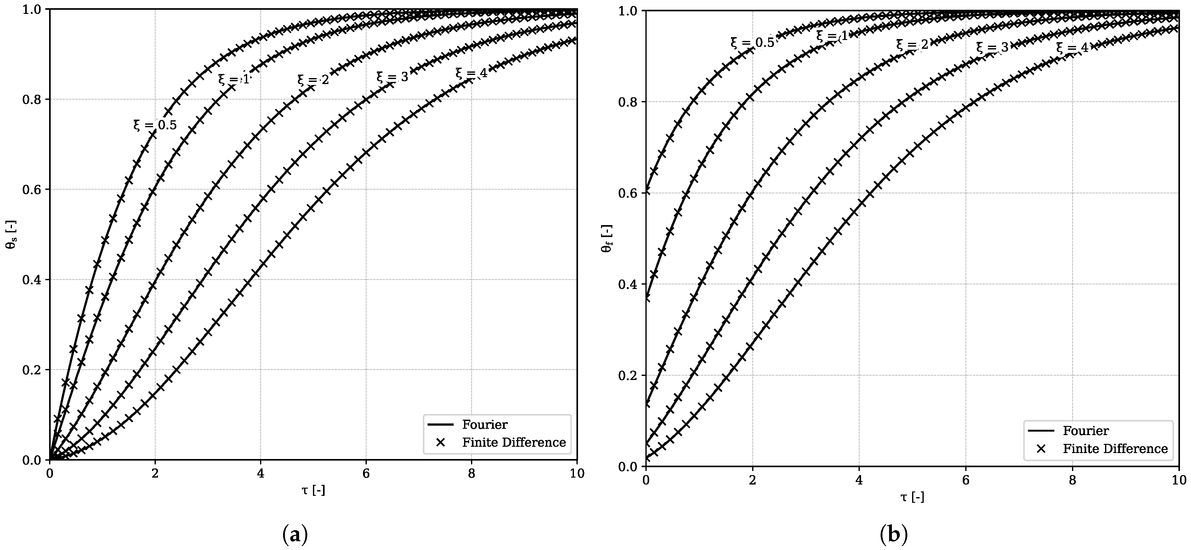
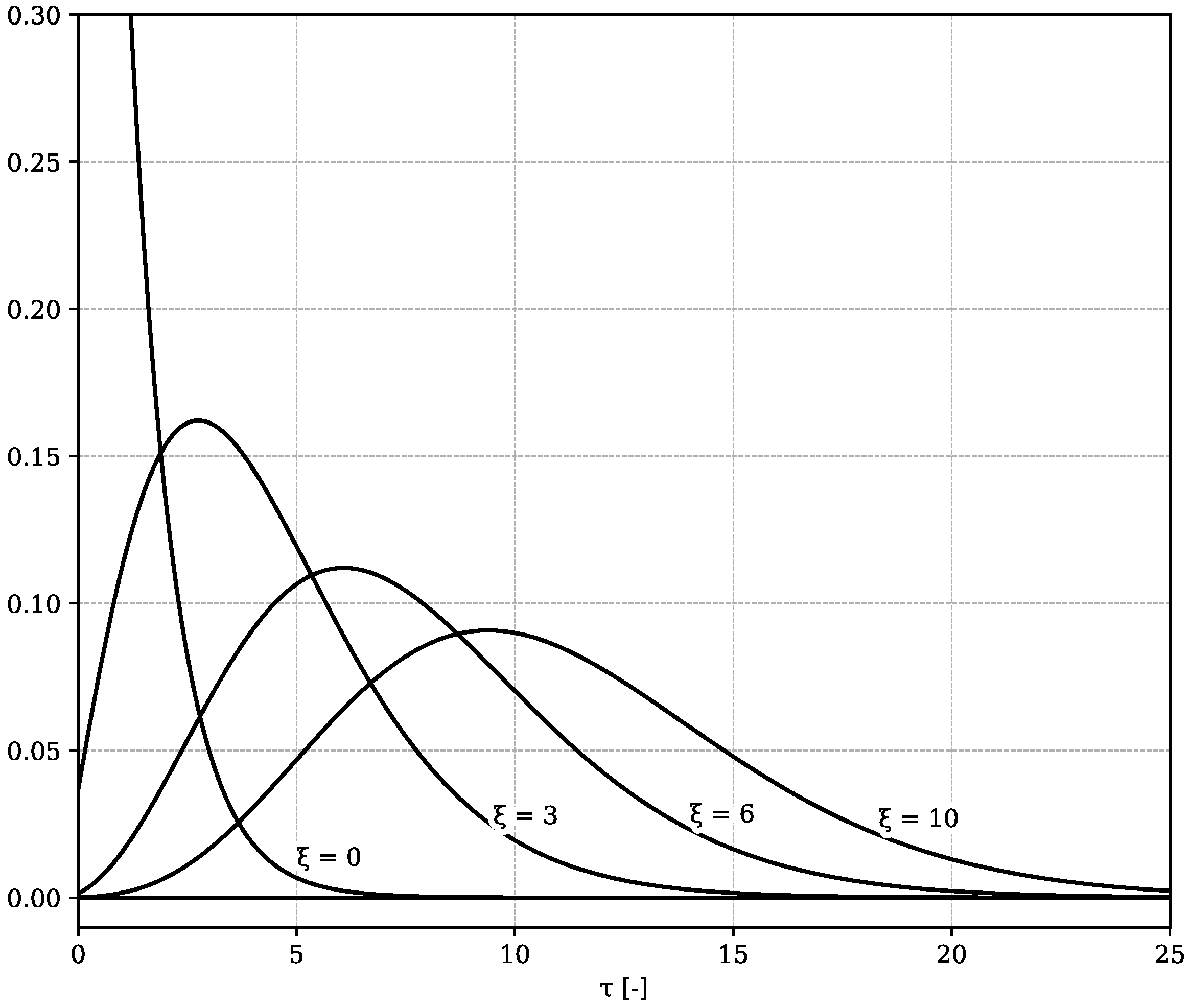
3. Fourier Transformation

The initial value problem will now be described by the propagation of an incident temperature step function through the porous medium. We assume a harmonic dependency
θ s , f = θ ^ s , f e i ( ω ˜ τ k ˜ ξ ) ,
for the temperatures with reduced frequency ω ˜ = ω / ω s and reduced wavenumber k ˜ = k ω f / u , with k being the wavenumber. Complex-value amplitudes are denoted with a hat. Note that k ˜ ξ = k x and ω ˜ τ = ω ( t x / u ) . The substitution of (10) in (8) and (9) leads to a simple set of linear relations:
i ω ˜ θ ^ s = θ ^ f θ ^ s ,
i k ˜ θ ^ f = θ ^ f + θ ^ s .
Eliminating the temperatures, we find that
k ˜ = ω ˜ 1 + i ω ˜ ,
and
β ( ω ) = θ ^ s / θ ^ f = 1 1 + i ω ˜ .
At arbitrary position ξ 0 , the temperatures are now given by
θ ^ s ( ξ , ω ˜ ) = β ( ω ˜ ) θ ^ 0 ( ω ˜ ) e i k ˜ ξ ,
θ ^ f ( ξ , ω ˜ ) = θ ^ 0 ( ω ˜ ) e i k ˜ ξ ,
where θ ^ 0 is the Fourier transform of the incident temperature step function.
After inverse Fourier transformation, these relations give the desired solid and fluid temperatures θ s ( ξ , τ ) and θ f ( ξ , τ ) . The results for the reduced solid and fluid temperatures are given in Figure 1. We recognize the typical diffusive behaviour of the solid and the fluid temperatures subject to Dirichlet and Neumann boundary conditions, respectively. The reduced solid temperature is zero initially and is then heated up by the arriving fluid. The hot fluid is at reduced temperature 1, initially, and is cooled down by heat transfer to the solid. Solid and fluid temperatures approach each other for larger ξ . A good measure for this is the fluid temperature at τ = 0 . We have that θ f = e ξ , which rapidly changes to zero as ξ increases.

4. Method of Integration

It was shown by Schumann [11] that (8) and (9) can be solved by introducing two new variables U and V:
θ s ( ξ , τ ) = ( U V ) e ξ τ ,
θ f ( ξ , τ ) = ( U + V ) e ξ τ .
The substitution of (17) and (18) in (8) and (9) leads to
U τ V τ = U + V ,
U ξ + V ξ = U V ,
and by further differentiation to
2 V ξ τ = V .
The boundary conditions for U and V are evidently
U ( ξ , 0 ) = V ( ξ , 0 ) = 1 2 ,
U ( 0 , τ ) = e τ 1 2 , V ( 0 , τ ) = 1 2 .
Schumann [11] showed that the solution to (21) that satisfies the boundary conditions is
V = 1 2 I 0 2 ξ τ ,
where I 0 is the modified Bessel function of the first kind. From (17), (18) and (8), we have that
θ f θ s = 2 V e ξ τ = θ s τ .
Integration for constant ξ yields that
θ s ( ξ , τ ) = 0 τ I 0 2 ξ τ e ξ τ d τ .
Once θ s is found, θ f is computed from (25):
θ f = θ s + I 0 2 ξ τ e ξ τ .
The integrand is a smooth function as shown in Figure 2. The resulting temperature curves are fully equal to the results for the Fourier method.

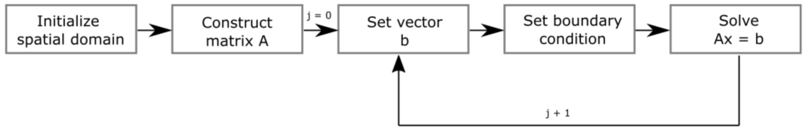
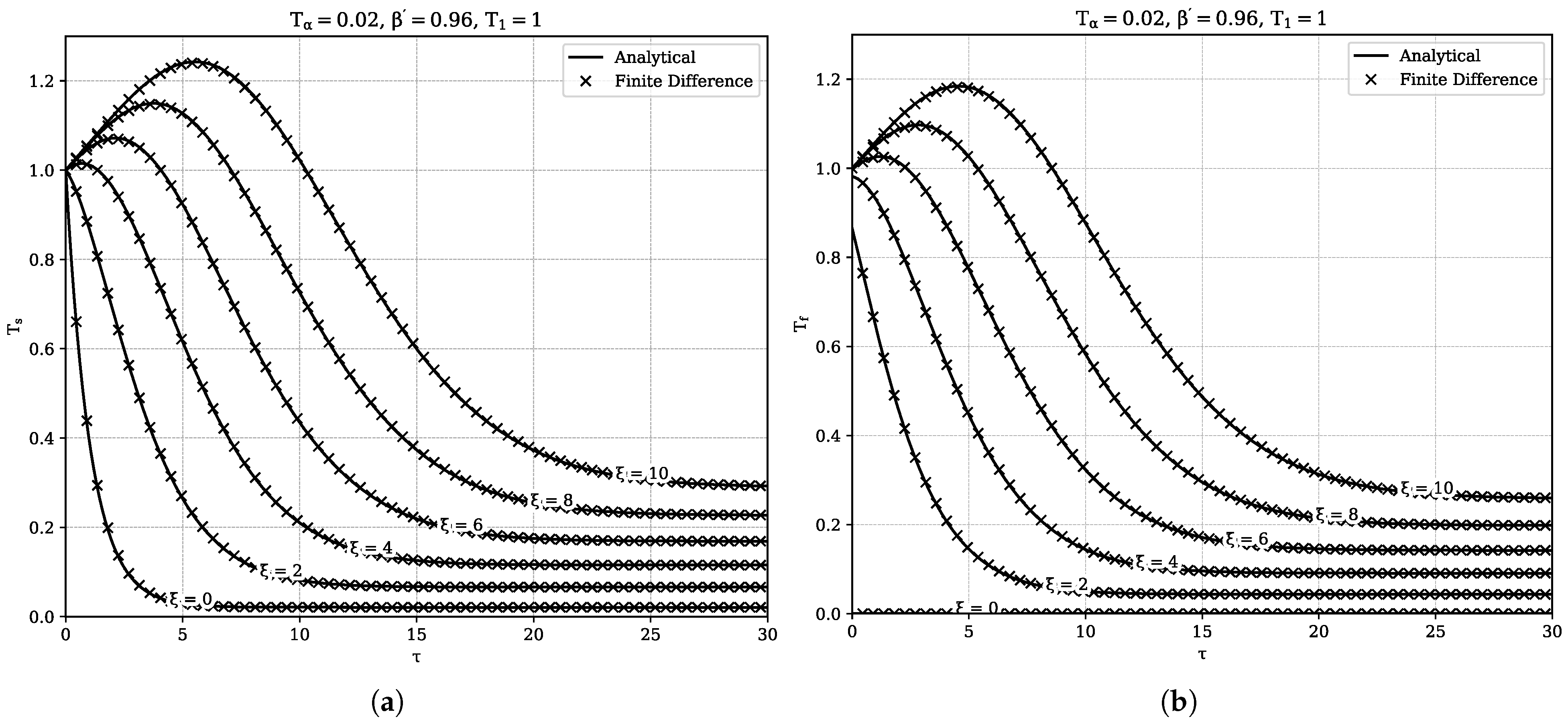
5. Finite Difference Method

The transport Equations (8) and (9) are discretized using third-order upwind spatial discretization and implicit time integration, resulting in two Finite Difference (FD) stencils that can be solved simultaneously:
θ s , i j + 1 θ s , i j Δ τ = θ f , i j + 1 θ s , i j + 1 ,
2 θ f , i + 1 j + 1 + 3 θ f , i j + 1 6 θ f , i 1 j + 1 + θ f , i 2 j + 1 6 Δ ξ = θ s , i j + 1 θ f , i j + 1 .
Here, i is used to increment ξ and j is used to increment τ . For each step j, the linear system of equations A x ¯ = b ¯ is solved for x ¯ , where A is a matrix populated by coefficients determined by the chosen discretization schemes, x ¯ is a vector containing the new temperatures and b ¯ is a vector containing the temperatures on the previous step and the boundary conditions. The solutions algorithm is schematically presented in Figure 3. Figure 1 shows the comparison between the Fourier solution and the solution obtained from the FD model where we have used Δ ξ = 0.01 and Δ τ = 0.01 .

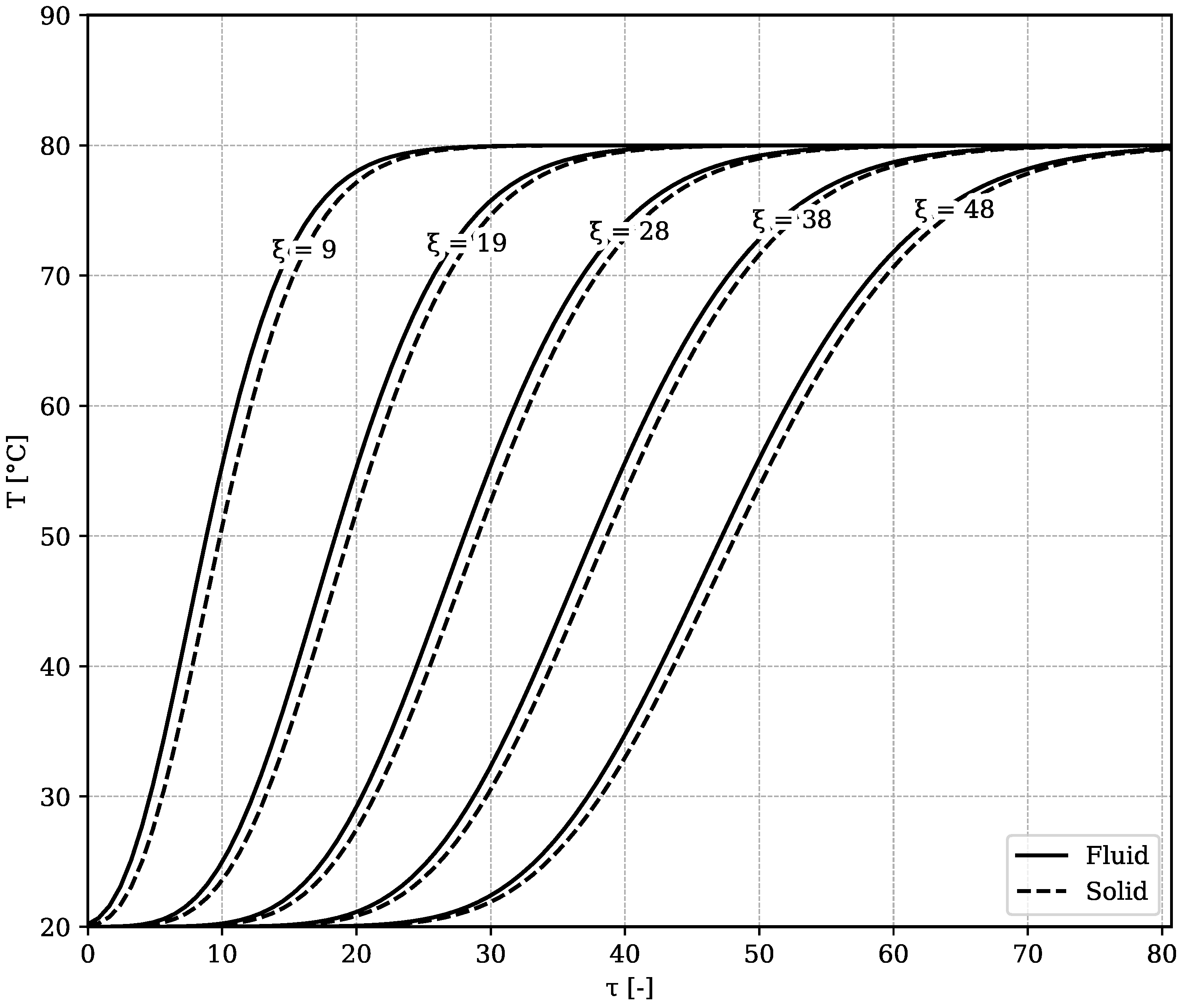
6. Practical Example

During the (dis)charging of sensible heat storage systems, heat is constantly exchanged between a solid phase and a fluid phase. During charging, heat is collected from, e.g., solar irradiation or cooling water from industrial plants and transferred via a heat exchanger to a carrier fluid, such as water or air. The carrier fluid transfers the heat to the solid storage material. A common storage material used for these systems is basalt. Parameters for a packed bed heat storage system are shown in Table 2.
For the configuration delineated in Table 2, ξ L = 48 and τ c h a r g e = 80.7 . In this particular problem, the basalt is initially at 20 °C and heated up to 80 °C. The reduced solid and fluid temperatures for all ( ξ , τ ) can be calculated from (26) and (27). The reduced temperature plot is shown in Figure 4. It can be seen that after considerable distance there are still differences between fluid and solid temperatures.

7. Convective Heat Transfer with Internal Heat Generation

The convective heating problem as described by Anzelius [10] and Schumann [11] was extended by Brinkley [12] by adding a linear heat generation term (internal heat generation in the solid is found in applications such as thermo-chemical and latent heat storage) to the solid temperature equation
ρ s C s ( 1 ϕ ) T s t = h S [ T f T s ( 1 β ) + T α ] ,
ρ f C f ϕ T f t + u T f x = h S ( T s T f ) ,
with heating constant T α and β . Using the same coordinate transformation as before and introducing β = 1 β , we obtain
T s τ = T f β T s + T α ,
T f ξ = T s T f .
Instead of heating up the porous rock, we set T s ( 0 , 0 ) = T 1 and cool it down with cold air of T f ( 0 , 0 ) = 0 :
T s = T 1 e β τ T α β e β τ 1 T f = 0 for ξ = 0 ; T s = T 1 T f = T 1 1 e ξ for τ = 0 .
Introducing
Γ = ( T s + T f ) e ξ + β τ ,
Δ = ( T s T f ) e ξ + β ξ ,
one obtains
2 Δ ξ τ = Δ ,
with boundary conditions
Γ = T 1 + T α β e β τ 1 Δ = T 1 + T α β e β τ 1 for ξ = 0 ; Γ = T 1 2 e τ 1 Δ = T 1 for τ = 0 .
The solution is given by
Δ = T 1 I 0 ( 2 ξ τ ) + T α β φ ( β τ , ξ / β ) ,
where
φ ( β τ , ξ / β ) = e β τ 0 β τ e β τ I 0 2 ξ τ d ( β τ ) .
Introducing
φ = φ ( ξ , τ ) , φ r = φ ( τ , ξ ) , φ ˜ = φ ( ξ / β , β τ ) , φ ˜ r = φ ( β τ , ξ / β ) ,
we also have that
T f ξ = T s T f = Δ e ξ β τ = T 1 I 0 e ξ β τ + T α β φ ˜ r e ξ β τ ,
so that
T f = T 1 e β τ 0 ξ I 0 e ξ d ξ + T α β e β τ 0 ξ φ ˜ r e ξ d ξ = e ξ β τ T 1 φ + T α β I B ,
where
I B = e ξ 0 ξ φ ˜ r e ξ d ξ .
The temperature of the solid is given by
T s = T f + Δ e ξ β τ = e ξ β τ T 1 [ φ I 0 ] + T α β [ I B + φ ˜ r ] .
Note that Brinkley [12] also wrote I B as follows:
I B = β β φ φ ˜ + e β τ e ξ / β e ξ ,
for β 0 . However, no derivation was given. A proof is now provided in Appendix A. We have that
T s = T 1 e ξ β τ ( φ + I 0 ) + T α β e ξ β τ β β φ φ ˜ + e ξ / β + β τ e ξ + β τ + φ ˜ r .
Using the identities
φ + φ r = e ξ + τ I 0 , φ ˜ + φ ˜ r = e ξ / β + β τ I 0 ,
we find that
T s = T 1 e ξ β τ ( e ξ + τ φ r ) + T α β e ξ β τ β β φ ˜ r φ r + e ξ + τ e ξ + β τ + β β φ ˜ r ,
which is rewritten as
T s = T 1 e β τ φ r e ξ β τ + T α β e ξ β τ φ ˜ r β φ r + e ξ + τ e ξ + β τ ,
or
T s = T 1 + T α β e β τ φ r e ξ β τ + T α β φ ˜ r β e ξ β τ 1 .
Note that there is a sign error in Brinkley’s Equation (26).
We can also solve (32) and (33) numerically using third-order spatial discretization and implicit time-stepping
T s , i j + 1 T s , i j Δ τ = T f , i j + 1 β T s , i j + 1 + T α ,
2 T f , i + 1 j + 1 + 3 T f , i j + 1 6 T f , i 1 j + 1 + T f , i 2 j + 1 6 Δ ξ = T s , i j + 1 T f , i j + 1 ,
again with ξ -increment i and τ -increment j. Using heating constants T α = 0.02 , β = 0.96 and T 1 = 1 and the same step sizes as before, (50) and (51) are solved. The comparison of solutions (41) and (49) and the numerical results is presented in Figure 5. Rock material near the inlet is immediately cooled down by the incoming air. Further downstream, the rock material is allowed to generate heat for a longer span of time without being simultaneously cooled down by the air. Moreover, the air passing by has already been heated up by the warmer rock upstream. For sufficiently large τ , T s and T f attain an equilibrium value dependent on ξ . Note that this does not mean the porous medium is in perfect local thermal equilibrium, as the solid temperature remains significantly higher than the fluid temperature. The third-order upwind scheme is again shown to produce perfectly accurate results compared with the analytical solution. The steady-state limit was also addressed by Brinkley [12].

8. Conclusions

In this work, we have presented and discussed different methods to solve the heating problem in a porous medium and obtain solutions for the temperatures of the solid and fluid phases as functions of space and time. Analytical solutions were obtained using Fourier analysis as well as with the method of integration. Results show that the propagating temperature front decays exponentially. Subsequently, the system of differential equations was also solved numerically using a Finite Difference model, which was able to perfectly replicate the analytical results. Finally, a linear heat source term in the solid phase was added to the system. Following and extending a solution procedure similar to Brinkley, analytical solutions for the solid and fluid temperatures as functions of ξ , τ were derived. Comparison with numerical methods again showed good agreement.

Author Contributions

Conceptualization, R.D. and D.S.; methodology, R.D. and D.S.; software, R.D. and M.W.; formal analysis, D.S.; investigation, R.D. and D.S.; resources, D.S.; data curation, R.D.; writing—original draft preparation, R.D. and D.S.; writing—review and editing, D.S.; visualization, R.D. and D.S.; supervision, D.S.; project administration, D.S.; funding acquisition, D.S. All authors have read and agreed to the published version of the manuscript.

Funding

This publication is part of the project Mat4Heat with project number 739.017.014 of the research program Mat4Sus, which is financed by the Netherlands Research Council (NWO).

Data Availability Statement

The calculations have been implemented in Python, using Spyder 3.8.8. All data obtained in the article can be reproduced using the methodology and the above formulas. In any case, the data that support the findings of this study are available on request from the corresponding author.

Conflicts of Interest

The authors declare no conflict of interest.

Appendix A

Integration by parts yields that
0 ξ e ξ φ ( β τ , ξ / β ) d ξ = φ ˜ r d e ξ = φ ˜ r e ξ 0 ξ + e ξ φ ˜ r ξ d ξ .
Brinkley [12] supplied the following useful property
φ ( x , y ) y = φ ( x , y ) y I 0 ( 2 x y ) ,
from which it can be derived that
φ ( y , x ) x = φ ( y , x ) x I 0 ( 2 x y ) ,
so that
β φ ˜ r ξ = φ ˜ β I 0 ξ .
Substitution yields
0 ξ e ξ φ ˜ r d ξ = φ ˜ r e ξ 0 ξ + 1 β e ξ φ ˜ r d ξ e ξ d I 0 ,
or
β β 0 ξ e ξ φ ˜ r d ξ = φ ˜ r e ξ 0 ξ e ξ I 0 0 ξ e ξ d I 0 .
Noting that φ ( β τ , 0 ) = e β τ 1 , I 0 ( 0 ) = 1 , and recognizing the definition of φ , we find
β β 0 ξ e ξ φ ˜ r d ξ = φ ˜ r e ξ e β τ + e ξ I 0 + e ξ φ = e ξ φ ˜ r + I 0 + φ e β τ + ξ .
Using the identity φ ˜ + φ ˜ r = e ξ / β + β τ I 0 , we finally have that
e ξ 0 ξ e ξ φ ˜ r d ξ = β β φ φ ˜ + e β τ + ξ / β e β τ + ξ .

References

  1. Trevisan, S.; Jemmal, Y.; Guedez, R.; Laumert, B. Packed bed thermal energy storage: A novel design methodology including quasi-dynamic boundary conditions and techno-economic optimization. J. Energy Storage 2021, 36, 102441. [Google Scholar] [CrossRef]
  2. Anderson, R.; Bates, L.; Johnson, E.; Morris, J.F. Packed bed thermal energy storage: A simplified experimentally validated model. J. Energy Storage 2015, 4, 14–23. [Google Scholar] [CrossRef]
  3. McTigue, J.D.; Markides, C.N.; White, A.J. Performance response of packed-bed thermal storage to cycle duration perturbations. J. Energy Storage 2018, 19, 379–392. [Google Scholar] [CrossRef]
  4. Ahmed, Z.; Constantin, A.; Bindra, H. The Thermal Response of a Packed Bed Thermal Energy Storage System upon Saturated Steam Injection Using Distributed Temperature Sensing. Energies 2022, 15, 3704. [Google Scholar] [CrossRef]
  5. Ma, X.; Fan, C.; Shao, W.; Cao, Q.; Cui, Z. Numerical and experimental studies of packed bed thermal energy storage system based on a novel transient energy model. Energy Sci. Eng. 2023, 11, 727–744. [Google Scholar] [CrossRef]
  6. Rindt, C.; Gaastra-Nedea, S. Modeling thermochemical reactions in thermal energy storage systems. In Advances in Thermal Energy Storage Systems; Elsevier: Amsterdam, The Netherlands, 2015; pp. 375–415. [Google Scholar]
  7. Gutfinger, C.; Abuaf, N. Heat transfer in fluidized beds. In Advances in Heat Transfer; Elsevier: Amsterdam, The Netherlands, 1974; Volume 10, pp. 167–218. [Google Scholar]
  8. Patil, A.V.; Peters, E.; Kolkman, T.; Kuipers, J. Modeling bubble heat transfer in gas–solid fluidized beds using DEM. Chem. Eng. Sci. 2014, 105, 121–131. [Google Scholar] [CrossRef]
  9. Oppong, F. Recent studies of heat transfer mechanisms in a fluidized bed. R D J. South Afr. Inst. Mech. Eng. 2018, 2018, 72–82. [Google Scholar]
  10. Anzelius, A. Über erwärmung vermittels durchströmender medien. ZAMM-J. Appl. Math. Mech. Angew. Math. Mech. 1926, 6, 291–294. [Google Scholar] [CrossRef]
  11. Schumann, T.E. Heat transfer: A liquid flowing through a porous prism. J. Frankl. Inst. 1929, 208, 405–416. [Google Scholar] [CrossRef]
  12. Brinkley, S.R., Jr. Heat transfer between a fluid and a porous solid generating heat. J. Appl. Phys. 1947, 18, 582–585. [Google Scholar] [CrossRef]
  13. Yang, K.; Vafai, K. Transient aspects of heat flux bifurcation in porous media: An exact solution. J. Heat Transfer. 2011, 133, 052602. [Google Scholar] [CrossRef]
  14. Villatoro, F.; Pérez, J.; Domínguez-Muñoz, F.; Cejudo-López, J. Approximate analytical solution for the heat transfer in packed beds for solar thermal storage in building simulators. In Proceedings of the Eleventh International IBPSA Conference, Glasgow, UK, 27–30 July 2009; pp. 709–715. [Google Scholar]
  15. Kuznetsov, A. An analytical solution for heating a two-dimensional porous packed bed by a non-thermal equilibrium fluid flow. Appl. Sci. Res. 1995, 55, 83–93. [Google Scholar] [CrossRef]
Figure 1. Reduced solid (a) and fluid (b) temperatures as a function of Lagrangian time τ for different reduced positions ξ , as obtained from the Fourier method and Finite Difference method. For the chosen Δ τ and Δ ξ , the maximum error for θ f = 3.7 % . The maximum error for θ s for the first ξ and first τ is large (36%) but decays rapidly.
Mathematics 11 04415 g001
Figure 2. Plot of I 0 2 ξ τ e ξ τ for different values of ξ . The area under each curve always approaches unity for τ .
Mathematics 11 04415 g002
Figure 3. Flowchart representation of the solution FD solution algorithm.
Mathematics 11 04415 g003
Figure 4. Temperature chart for a basalt heat storage system, similar to Figure 1a,b.
Mathematics 11 04415 g004
Figure 5. τ -series of the reduced solid (a) and fluid (b) temperatures evaluated at several ξ -coordinates, as calculated by the analytical solution and the FD model. A high degree of agreement is noted between the analytical and numerical solutions. For the chosen Δ τ and Δ ξ , the maximum error is 6%.
Mathematics 11 04415 g005
Table 1. Model assumptions and their justifications.
AssumptionJustification
1-D flowtube configuration
conduction neglected P e = u d p a f = 0.1 × 0.04 2.3 × 10 5 = 174 > > 1
constant fluid flowexperimental implementation
no heat exchange with environmentgood setup insulation
linear internal heat generation for Brinkley model (see Section 7)following Brinkley assumption that heat is generated by chemical reaction
semi-infinite domainlong-tube experiment
Table 2. Parameters for a packed bed heat storage system.
ParameterDescriptionValueUnit
Lreactor length5m
t c h a r g e timescale75,000s
ϕ porosity0.2-
Sspecific area1201/m
ρ s solid density2900kg/m 3
C s solid heat capacity900J/kgK
ρ f fluid density1.11kg/m 3
C f fluid heat capacity1008J/kgK
ufluid velocity0.1m/s
d p solid particle diameter0.04m
hheat transfer coefficient18.7W/m 2 K
k f thermal conductivity0.026W/mK
α f thermal diffusivity k f ρ f C f = 2.3 × 10 5 m 2 /s
ω s solid convective coefficient h S ρ s C s ( 1 ϕ ) = 10 3 1/s
ω f fluid convective coefficient h S ρ f C f ϕ = 9.6 1/s
T 0 inlet temperature80°C
T 1 initial temperature20°C
Disclaimer/Publisher’s Note: The statements, opinions and data contained in all publications are solely those of the individual author(s) and contributor(s) and not of MDPI and/or the editor(s). MDPI and/or the editor(s) disclaim responsibility for any injury to people or property resulting from any ideas, methods, instructions or products referred to in the content.

