Article

Event-Triggered Second-Order Sliding Mode Controller Design and Implementation

Faculty of Electrical Engineering and Computer Science, University of Maribor, 2000 Maribor, Slovenia
*
Author to whom correspondence should be addressed.
Mathematics 2023, 11(20), 4314; https://doi.org/10.3390/math11204314
Submission received: 11 September 2023 / Revised: 9 October 2023 / Accepted: 13 October 2023 / Published: 16 October 2023
(This article belongs to the Special Issue Advances in Nonlinear Dynamical Systems and Control Systems)

Abstract

:
The paper presents an event-triggered higher-order sliding mode controller design. The event-triggering technique is the alternative approach to real-time controller execution, unlike the classic time-triggering technique, which is not time-dependable and is governed by the triggering policy. The technique is suitable for system resource relaxation in case of computation burden or network usage mitigation. The paper describes the stability analysis of the super-twisted sliding mode controller based on input-to-state stability notation. The stability analysis introduces a triggering policy related directly to the ultimate boundness of the system states and preselected sliding variables. The controller time execution with the selected triggering condition prevents the exhibition of the Zeno phenomena, where the minimal inter-event time of the controller has a positive non-zero lower bound. The minimal value of the inter-event time is related directly to the controller parameters and triggering bound, the selection of which is given with the derived stability conditions regarding the designer’s objective. Preventing the fast nonlinear controller execution, especially close to the sliding manifold, also alleviates the chattering phenomena effectively, which is a primal drawback, and limits the usage of the controller on various systems. The method’s efficiency is verified with the hardware-in-the-loop system, where the dynamic and robustness of the triggering approach are compared to the standard time-triggered execution technique.

1. Introduction

The new methodology of the sampled system opens many areas of system optimization, resource management, scheduling, and data transfer. The classic computer implementation of a feedback system utilizes fixed-time data rates and precise algorithm execution [1,2]. Most modern feedback systems rely on the utilization of the time-triggering decision rule. Such an approach can sometimes be too conservative, leading to insufficient resource utilization. For example, an equidistant timer-triggering approach can lead to excessive usage of the communication link in the networked feedback system or distributed system [3], or inadequate computation power for fast dynamic systems, where classic approaches of the discrete system cannot be retained [4,5]. A recent paradigm offers a triggering mechanism for the controller update, which is not strictly time-dependent and only occurs when control action is needed. Such an approach does not sample the system in an equidistant time interval and involves the execution action according to the prescribed triggering rule. Even though constant periodicity is omitted, computation relaxation can be achieved. Such an approach still needs to preserve the closed-loop properties regarding stability, state convergence, and time performances [6]. It is of great interest to design an approach that can ensure the above-mentioned properties and does not rely on periodic time triggering. The main difference between the time-triggering (TT) and event-triggering (ET) control is that the ET involves the triggering rule based on the specific condition of the system states and is time-independent.
Many scholars have considered ET control in different scenarios and applications. The authors in [7] studied ET design in networked systems, where the controller and the plant are in the cyber-physical structure over a wireless network. The studies deal with distributed systems in the ET approach by introducing different communication protocols with delay and adaptive data payload management [8,9,10,11]. The work considered the ET approach for the pinned-networked system, where the usage of the network is relinked over different members in the controlled area in the network [12,13]. Conventional controller structures with ET mechanisms are studied extensively in networked controlled and distributed systems. The classic PID controller with an event-triggering mechanism is studied in [14,15,16,17]. The stability analysis of PID-ET with different numerical implementation approaches is studied in [18]. The authors in [19] studied different ET linear high-order controllers in the continuous domain. The presented approach is also analyzed for the linear state space approach [20].
The advanced ET studies introduced a proactive approach, a self-triggering (ST) mechanism, studied in [21,22]. The advantage of ST is the system’s self-decision regarding the controller execution. An essential part of the ST is the accurate prediction of the further system response and planned adequate controller move. The approach is naturally similar to the model predictive control (MPC) paradigms. The key difference between ST and MPC is the intention of triggering mechanism relaxation without further controller move optimization. Regarding the latter, the MPC is subsequently the objective of the ET design studied in works [23,24,25]. The accuracy of the prediction is the subject of much research. The exactness of the mathematical models is limited and suffers from unknown and complex dynamics, uncertainties, and unknown disturbances. Moreover, the complexity of the prediction can limit or restrain controller operation in the real-time system. In many systems with complex and nonlinear dynamics, ST sometimes cannot guarantee proper performance or can even lead to the unstable operation of the feedback system. To avoid modeling and nonlinear equations’ complexity, the authors proposed soft-computing techniques to mitigate the stated shortcomings [26,27,28]. Moreover, hybrid ET schemes were proposed in works [29,30,31]. The studies introduce a delayed and chaotic system for network synchronization and actuator fault detection under the ET policy.
With regard to the aforementioned factors, the ET approach is studied and analyzed for nonlinear design techniques. For example, the sliding mode control (SMC) is subject to different ET design procedures [32,33,34,35,36]. The SMC approach is a nonlinear controller design technique used to achieve robustness and the desired performance criteria of the feedback system in the presence of the system’s nonlinearities, uncertainty, and disturbance [37,38]. The key characteristic of the SMC is discontinuous control action regarding the preselected sliding variable, where the control switches between different controller structures to keep the system’s trajectory on the sliding surface [39]. This switching behavior makes sliding mode control suited for complex and uncertain systems. Despite the SMC’s prowess in handling uncertainties and disturbance, the key drawback is the nonlinear output, which refers to the high-frequency oscillation around the sliding manifold [40]. High-frequency oscillation is an undesirable phenomenon for systems, which causes wear of the physical system, unwanted vibration, and excessive heat dissipation. Several studies address chattering phenomena and analyze different methods for their suppression. For example, the second-order sliding mode controller, known as the super-twisted algorithm (STA), was a subsequent solution to reduce output oscillation by placing the nonlinear term behind the integrator, ensuring continuous output and preserving the properties of the first-order SMC [41,42]. Regarding work [43], the chattering phenomena can be suppressed effectively only for first- and second-order systems, where the parasite dynamics are not considered. The chattering phenomena alleviation with the digital implementation of the SMC controller attracts the interest of scholars [41,44,45,46,47,48].
The event-triggered sliding mode control (ET-SMC) approach has excellent potential for the NCS system and can be considered a novel chattering alleviation technique. In work [49], the ET approach for first-order SMC controllers is analyzed in terms of the embedded system’s computational complexity. The ET schemes for first-order SMC with uncertainty and delay are presented in [50]. Higher-order SMC controllers, such as STA with ET techniques, do not have much-reported design procedures and analysis.
This paper deals with the stability analysis of the STA controller with the ET execution technique. Most event-triggered SMC research deals with the first-order SMC, where the state boundary and the lower positive inter-event time are presented [49,51]. The work aims to analyze the event-triggered STA (ET-STA) stability conditions based on the input-to-state stability (ISS) paradigm. The stability of the closed-loop system and triggering conditions are derived directly from the STA-SMC reaching phase stability analysis. The stability of the sliding phase is studied further for the rest of the modified closed-loop system with STA, where the direct correlation is presented between the closed-loop dynamic and the triggering boundary. The study also involves the Zeno phenomena analysis, where the minimal positive lower boundedness of the controller execution time is essential for controller realization. The derived ET-STA parameter correlation with the state boundaries and triggering policy offers the designer a transparent approach for controller parameter selection to achieve the desired closed-loop performance. The ET-STA is further compared with a standard STA executed with the TT technique. In contrast to the STA, the ET-STA algorithm excels in improved chattering properties and reduced computation burden. Both controllers are tested on the hardware-in-the-loop system (HIL), where the controllers are implemented on the embedded system. Regarding the computation burden relaxation, the NSC deployment with a longer execution time and delays is favorable.
The structure of the paper is as follows: Section 2 involves the preliminaries of the ISS stability analysis for the class of nonlinear systems. Section 3 introduced stability conditions regarding the ET-STA policy. Section 4 introduces the analysis of the lower nonnegativity boundary of the inter-event time. Section 5 presents the results of the ET-STA in comparison with the standard TT technique. Section 6 is the conclusion of the work and a brief introduction of possibilities of further research.
Standard notations are used in the paper.  ·  and  ·  denote the absolute value and Euclidian norm, respectively. Matrix  Q n × n  is positive definite  Q 0 , if  x T Q x > 0  for any  x 0 , x n  and  x T Q x = 0  if  x = 0 , x n . The notation  λ min Q  or  λ max Q  means the smallest or largest eigenvalue of a matrix  Q . The notation  z = x , y  represents an inner product of the vectors  x , y . Regarding the ISS stability theorem, the function  α : 0 , 0 α 0 = 0  is a of class-𝒦 if it is increasing strictly, and  α t  of class-𝒦 if it is of class-𝒦 and tends to ∞ with respect to  t .

2. Preliminaries

Consider the following single-input, single-output nonlinear system of the following class,
x ˙ 1 = f 1 ( x 1 ) + x 2 , x ˙ 2 = f 2 ( x 1 , x 2 ) + g u + d ,
where  x 1 n 1  and  x 2  are the system states, and  u  and  d  are the control input and external disturbance, respectively. Function  g  are the input gain function, where it holds that  g 0 . The given assumptions are used for further analysis.
Assumption 1.
Nonlinear functions  f 1 ( x 1 )  and  f 2 ( x 1 , x 2 )  have a unique equilibrium point, where, without the loss of generality, it holds that  f 1 ( 0 ) = 0  and  f 2 ( 0 , 0 ) = 0 . Functions can be represented with linear and nonlinear terms. The functions are bounded  f 1 ( x 1 ) F 1  and  f 2 ( x 1 , x 2 ) F 2 , where it holds that  F 1 0  and  F 2 0  are known constants.
Assumption 2.
Nonlinear functions  f 1 ( x 1 )  and  f 2 ( x 1 , x 2 )  are Lipschitz with respect to the  x 1  and  x 2  in a compact domain  n . There exists constant L, such that  f 1 ( z 1 ) f 1 ( z 2 ) L z 1 z 2 , which holds for any  z 1 , z 2  𝒟, and  f 2 ( z 1 ) f 2 ( z 2 ) L z 1 z 2 ,  z 1 , z 2  𝒟, where  z = x 1 , x 2 .
Assumption 3.
Suppose that the matched external disturbance  d ( t )  with respect to the control input  u ( t )  is a continuously differentiable function, where exist some positive constants  Δ d  and  ς d  and it holds that sup  t 0 d t < Δ d , sup  t 0 d ˙ t < ξ d .
The system dynamic given (1) is rewritten as,
x ˙ = f ( x ) + G u + d , x 0 = x 0 ,
where  x = x 1 ; x 2 n f x = f 1 x 1 f 2 x 1 , x 2 T n , and  G = 0 g T n . In an event-triggered approach, the controller update is related to the prescribed triggering interval. Unlike the classic sampling approach, which introduces a fixed update interval, the ET technique is not time-dependent, and the system is stable in the sense of the preselected triggering boundary. The ISS analysis introduced by Sonntag [52] is a generalized stability form of the Lyapunov stability approach, where the functions of class-𝒦 and class-𝒦 are introduced for the selected Lyapunov candidate. For example, consider the case where the system is described as  x ˙ = f ( x , u ) , where  u  is a control input and the control law  u = k ( x )  such that the closed loop system  x ˙ = f ( x , k ( x ) )  is stable. Suppose the controller is implemented with a sample and holds (SH) technique, where the inter-event time between two consecutive controller updates is  t i  and the controller is  u ( t ) = k ( t i ) . Due to the SH technique, an error exists between the current state and the last update, which is defined as  e ( t ) = x ( t ) x ( t i ) . Then, there exists the Lyapunov function candidate, such that:
α 1 x V x α 2 x ,
and its derivative,
V x x f ( x , k ( x ) ) α 3 x + γ e ,
where  α 1 α 2 α 3  are class-𝒦 functions, and  γ  is a class-𝒦 function. The system is ISS stable regarding the error  e  if the triggering condition is derived in a way that meets the given criteria,
γ e λ α 3 x λ 0 , 1 ,
where the error  e  is bounded  α 3 1 , and  γ  is Lipschitz and holds  e λ L x x . The  L x  is a Lipschitz constant and  λ  the scaling factor, respectively. Regarding conditions (4) and (5), it follows that:
V ˙ ( 1 λ ) α 3 x < 0 .
The condition (6) provides the asymptotic stability of the system with control law  u = k ( x )  only if the triggering rule is designed to fulfill criteria (5).

3. Event-Triggering Super-Twisted Controller Design

A super-twisted algorithm (STA) is known as a second-order sliding mode controller, designed primarily to overcome the unwanted behavior of the first-order SMC (FOSMC). The STA preserves all the desired characteristics of the FOSMC, where the chattering phenomena are suppressed by placing the nonlinear function behind the integrator term. Regarding the research and scholars, the chattering can be suppressed effectively only for first- and second-order systems [39,40]. In the real scenario, each system contains an unmodeled and parasitic dynamic. Moreover, different digital implementation techniques cause unwanted behavior in the closed-loop system and the chattering controller output. For most SMC digital implementation techniques, the frequency of the chattering phenomena is proportional to the preselected sampling time. The given paper aims to design an event-triggered STA which relaxes the computation effort and alleviates the high-frequency chattering phenomena. In event-triggering control, the controller output is updated in the discrete-time sequence,
t 0 , t 1 , t 2 , , t i , i = 1 , 2 ,
where  t i i = 0  is an event-triggering instant satisfying the conditions  t i + 1 > t i , with  t 0 0  being the initial sampling instant. Without a loss of generality, the initial sampling instant can be selected as  t 0 = 0 . The event-triggering instants are not uniformly distributed and constant  t t i , t i + 1 . The controller  u  is updated at the instance  t i  and holds the last value until the next triggering event occurs at  t i + 1 . The inter-event time is defined as  T i = t i + 1 t i i = 0 , where the induced error is defined as  e ( t ) = x ( t ) x ( t i ) . At the time of update  t i , the error is  e t = 0 , where it holds that  e ( t ) = x ( t i ) x ( t i ) = 0 .
For the system given in (2), the sliding variable is defined as
s = c x
where  c = c 1 1  and  x = x 1 x 2 T . Regarding the discrete implementation of the controller, the practical sliding mode occurs and is defined by
S x n s = c x < ε , ε > 0 .
The practical sliding mode is discussed in the work [33], and represents the ultimate bounded sliding variable in the prescribed region around the sliding manifold, which is independent of the disturbance bound and preselected sampling interval. In an event-triggering manner, the boundary  ε  is related to the preselected triggering condition.
The STA controller [53] for the system (2) is given as
u t = c G 1 c f ( x ) k 1 s t 1 / 2 s i g n s t + v t v ˙ t = k 2 s i g n s t .
Regarding the idea of the ET technique, the controller is updated only at the time  t i . The ET-STA controller is defined as
u t = c G 1 c f ( x t i ) k 1 s t i 1 / 2 s i g n s t i + v t i v ˙ t = k 2 s i g n s t i .
Theorem 1.
The event triggering for a system given in (2) and the controller (11) is established, if, for a given error function,  e t  and triggering parameter  β  holds,
c e t < β ,
for all   t > 0 , and   β ,   β > 0 , where the controller gains are selected as
k 1 > 3 2 k 2 + G ξ d + η k 2 7 3 + G ξ d + η ,
and it holds that  η 0 .
Proof. 
The attraction of the system variables (2) with the controller (11) to the preselected sliding variable (8) is proven with the Lyapunov stability theorem. A closed-loop system with ET-STA is
x ˙ = f ( x ) c 1 c f ( x ¯ ) k 1 s ¯ 1 / 2 s i g n s ¯ + v ¯ + G d , v ˙ t = k 2 s i g n s ¯ .
For brevity, variables at the last updates are assigned with an overline, for example,  s t i = s ¯ . Regarding the given condition (12), the reaching phase of the SMC with a sliding variable (8) is analyzed for the inter-event time  t t i , t i + 1 . The Lyapunov function used is  V t = 1 2 s t 2 , where the derivative of  s  with respect to time and condition (13) is
s ˙ = c x ˙ , s ˙ = c f ( x ) f ( x ¯ ) k 1 s ¯ 1 / 2 s i g n s ¯ + v ¯ , v ˙ t = k 2 s i g n s ¯ + G d ˙ .
The stability of the sliding variable is proven similar to the approach in [38] with introduced new variables, given as
ζ = ζ 1 ζ 2 T = s 1 / 2   s i g n s       v T ,
where the rewritten system (16) is equal to
ζ ˙ 1 = 1 2 ζ 1 c f ( x ) f ( x ¯ ) k 1 s ¯ 1 / 2 s i g n s ¯ + v ¯ , ζ ˙ 2 = k 2 s i g n s ¯ + G d ˙ ,
where  ζ 1 = s 1 / 2 .
The compact form of expression (17) is given as
ζ ˙ = 1 ζ 1 A ζ ¯ 1 ζ 2 + B ,
where  A  is
A = 1 2 k 1 1 0 0 ,
and  B  is
B = 1 2 c f ( x ) f ( x ¯ ) ζ 1 k 2 s i g n s ¯ + G d ˙ .
For the stability analysis of the system (15), the given Lyapunov function  V s  is used:
V s = ζ T P ζ ,
where  P  is a symmetric matrix, given as:
P = 4 k 2 + k 1 2 k 1 k 1 1 .
The derivative of (21) along (18) is
V ˙ s = ζ ˙ T P ζ + ζ T P ζ ˙ V ˙ s = 1 ζ 1 ζ T P A ζ ¯ 1 ζ 2 + ζ ¯ 1 ζ 2 A T P ζ + 2 ζ T P B
V ˙ s = 1 ζ 1 4 k 1 k 2 + k 1 3 ζ ¯ 1 ζ 1 + k 1 2 ζ ¯ 1 ζ 2 + 4 k 2 + k 1 2 ζ 1 ζ 2 k 1 ζ 2 ζ 2 + 2 k 1 k 2 ζ 1 s i g n s ¯ ζ 1 2 k 1 G ζ 1 ζ 1 d ˙ 2 k 2 ζ 1 s i g n s ¯ ζ 2 + 2 G ζ 1 ζ 2 d ˙ + 2 c 4 k 2 + k 1 2 f ( x ) f ( x ¯ ) ζ 1 2 c k 1 f ( x ) G 1 f ( x ¯ ) ζ 2 .
According to Assumption 3 and relation  ζ 1 s i g n s ¯ ζ 1 , the derivative of  V s  is
V ˙ s 1 ζ 1 4 k 1 k 2 + k 1 3 ζ ¯ 1 ζ 1 + k 1 2 ζ ¯ 1 ζ 2 + k 1 2 + 2 k 2 + 2 G ξ d ζ 1 ζ 2 + 2 k 1 k 2 k 1 G ξ d ζ 1 ζ 1 k 1 ζ 2 ζ 2 + + 2 c 4 k 2 + k 1 2 f ( x ) f ( x ¯ ) ζ 1 2 c k 1 f ( x ) G 1 f ( x ¯ ) ζ 2 .
The stability has to be analyzed for the condition when  ζ 1 s i g n s ¯ = ζ 1 s i g n s , and for  ζ 1 s i g n s ¯ ζ 1 s i g n s . In the case where the sliding variable  s  starts from the same region as the last values  s ¯ , it can be assumed that  ζ 1 ζ 2 ζ 1 ζ 2 . Regarding Assumption 2, it holds that  f ( x ) f ( x ¯ ) L x x ¯ . The expression can be rewritten further as
V ˙ s 1 ζ 1 4 k 1 k 2 + k 1 3 ζ ¯ 1 ζ 1 + k 1 2 ζ ¯ 1 ζ 2 + k 1 2 + 2 k 2 + 2 G ξ d ζ 1 ζ 2 + 2 k 1 k 2 k 1 G ξ d ζ 1 2 k 1 ζ 2 2 + + 2 c 4 k 2 + k 1 2 L x x ¯ ζ 1 2 c k 1 L x x ¯ ζ 2
From the last triggering instant, the sliding variable is bounded by
s ¯ = s + c x x ¯ ,
where
s ¯ s + c x x ¯ .
The difference  x x ¯  is an update error between the current state and the state from the last update, and can be defined as  e = x x ¯ . Regarding the preselected triggering rule (12) and the condition (25), it holds that:
s ¯ s + c e s + c β .
A further extension for variables (16) is
ζ ¯ 1 ζ 1 + β ˜ ,
where  β ˜ = β 1 2 . Substitute (27) to (23) gives
V ˙ s 1 ζ 1 4 k 1 k 2 + k 1 3 ζ 1 + β ˜ ζ 1 + k 1 2 ζ 1 + β ˜ ζ 2 + k 1 2 + 2 k 2 + 2 G ξ d ζ 1 ζ 2 + 2 k 1 k 2 k 1 G ξ d ζ 1 2 k 1 ζ 2 2 + + 2 4 k 2 + k 1 2 L β ζ 1 2 k 1 L β ζ 2 .
A rearrangement of the expression gives
V ˙ s 1 ζ 1 2 k 1 k 2 2 k 1 G ξ d k 1 3 ζ 1 2 + 2 k 1 2 + k 2 + G ξ d ζ 1 ζ 2 k 1 ζ 2 2 + 8 k 2 L β + 2 k 1 2 L β 4 k 1 k 2 β ˜ k 1 3 β ˜ ζ 1 2 k 1 L β k 1 2 β ˜ ζ 2 ,
where the matrix form (28) is given as
V ˙ s 1 ζ 1 ζ 1 ζ 2 Q ζ 1 ζ 2 + 1 ζ 1 Υ ζ 1 ζ 2 1 ζ 1 Ζ T Q Ζ + Υ Ζ ,
where the new state variable  Ζ T = ζ 1 ζ 2  and matrices  Q Υ  are
Q = 2 k 1 k 2 + 2 k 1 G ξ d + k 1 3 k 1 2 2 + k 2 + G ξ d k 1 2 2 + k 2 + G ξ d k 1 ,
Υ = 8 k 2 L β + 2 k 1 2 L β 4 k 1 k 2 β ˜ k 1 3 β ˜         2 k 1 L β k 1 2 β ˜ .
To fulfill the inequality (29), the matrix  Q  has to be a strict positive definite, and controller gains  k 1  and  k 2  can be selected as
k 1 > 3 2 k 2 + G ξ d + η k 2 7 3 + G ξ d + η .
The parameter  η  is an additional tuning parameter selected as  η 0 . The positive definiteness of matrix  Q  fulfills the condition,
λ min ( Q ) Ζ 2 Ζ T Q Ζ λ max ( Q ) Ζ 2 ,
and holds that
V ˙ s 1 ζ 1 λ min ( Q ) Ζ 2 + 1 ζ 1 Υ Ζ
The state variable  ζ t  is stabilized in the region  Ω = ζ n ζ Υ λ min ( Q )  derived from the condition (34):
1 ζ 1 λ min ( Q ) Ζ 2 + 1 ζ 1 Υ Ζ 0 λ min ( Q ) Ζ + Υ 0 Ζ Υ λ min ( Q )
With respect to  ζ 1 ζ  and  ζ 1 = s 1 / 2 , it can be concluded that the sliding variable  s t  is attracted to the region:
s Υ 2 λ min ( Q ) 2
It needs to be mentioned that the region (35) is unstable, and coincides with the controller action phase when no update occurs. It follows that the sliding variable enters the region (35) and remains in the future, ensuring stability with the triggering bound  β . For the stability for the case  s i g n s ¯ s i g n s , it has to be proven that the sliding variable is ultimately bounded. When sliding variables enter the region (35), the triggering mechanism holds the last output until the variable approaches the boundary, and the controller is updated with a new value and guides the sliding variable back into the region (35). The given region after the last update is given as
s t s t i = c x x ¯ c e β
The rest of the proof introduces the stability of the remaining system state  x 1  when the sliding variable enters the region (35). Regarding the sliding variable (8),
x 2 = s c 1 x 1
The stability is analyzed with a selected Lyapunov function  V 1 t = 1 2 x 1 t 2 , and the derivative of  V ˙ 1 t  along  x 1  is
V ˙ 1 t = x 1 x ˙ 1 = x 1 f 1 ( x 1 ) + x 2 = x 1 f 1 ( x 1 ) + s c 1 x 1 = c 1 x 1 2 + F 1 x 1 + s x 1 c 1 F 1 x 1 2 + s x 1 c 1 F 1 x 1 2 + β x 1
It is clear that the  x 1  is ultimately bounded with a triggering condition (12) if  c 1 F 1 > 0  holds. This is the end of the proof. □

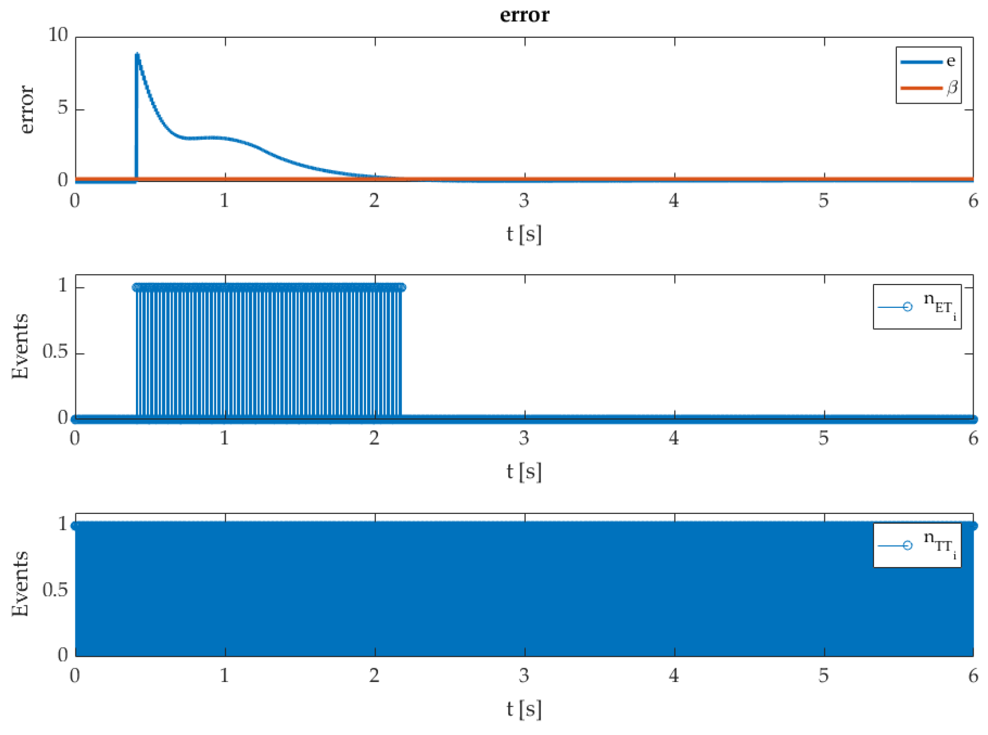
4. Admissible Inter-Event Time of the ET-STA

Regarding the idea of the SMC approach that leads the system states to the prescribed sliding variable by employing the nonlinear switch function, it maintains the sliding variable equal to zero even when uncertainty and disturbance are presented in the system. By the first-order SMC, the Zeno phenome is exhibited in the system when the algorithm tries to keep the sliding variable at the sliding manifold in the presence of uncertainty or disturbance. Zeno phenomena perform infinite controller updates in a finite time, and restrict the practical implementation of the algorithm by posing the chattering phenomena. Such behavior of the controller output can potentially harm or exert wear on the system. It is necessary to avoid and mitigate the unwanted phenomena. In the given approach, the ET mechanism lowered the controller actions naturally, and effectively alleviated the chattering phenomenon presented in the work [49].
For ET-STA, it is necessary to ensure that the minimum inter-event time  T min  has a positive lower bound  T min > 0 . The inter-event time  T i  is the time between two successive controller updates, and is not fixed during controller operation. The lower boundness of time  T i  is also crucial regarding the system computation capability. The inter-event time is analyzed with the controller structure (11) and the triggering condition (12).
Theorem 2.
Consider a system (2) with a controller structure (11) and triggering condition (12). The inter-event time  T i  is positive-lower-bounded if the function  Φ T i ,
Φ T i 1 L 2 k 2 c L T i + κ L k 2 c L t i k 2 c e L T i 1 c 1 β ,
is  Φ T min 0 , where  T i T min > 0 , and holds for all  t > 0  and triggering sequences  t i i = 0 .
Proof. 
The inter-event time  T i  for the subsequent control execution  t i + 1  is a time that lets the error  e t  grow from zero to  c 1 β . Define  Π t t i , t i + 1 : e t = 0 , for  t t i , t i + 1 \ Π , where inequality holds:
d d t e t d d t e t , = d d t x ( t ) x ( t i ) = d d t x ( t ) = f ( x ) f ( x ¯ ) c k 1 s ¯ 1 / 2 s i g n s ¯ c k 2 t i t s i g n s ¯ d t + G d f ( x ) f ( x ¯ ) k 1 c s ¯ 1 / 2 k 2 c t t i + G d L e t k 2 c t k 1 c s ¯ 1 / 2 + k 2 c t i + G Δ d L e k 2 c t + κ ,
where  κ = k 1 c s ¯ 1 / 2 + k 2 c t i + G Δ d . The differential equation is solved with the initial condition  e t i = 0 . The solution of differential inequality given in (39) is
e t κ k 2 c t L k 2 c κ L k 2 c L t i k 2 c e L t t i L 2 .
The inequality (40) can be rewritten as
e t κ L + k 2 c L t k 2 c κ L k 2 c L t i k 2 c e L t t i L 2 κ L + k 2 c L t + k 2 c L t i k 2 c L t i k 2 c κ L k 2 c L t i k 2 c e L t t i L 2 κ L + k 2 c L T i + k 2 c L t i k 2 c κ L k 2 c L t i k 2 c e L T i L 2 1 L 2 k 2 c L T i + κ L k 2 c L t i k 2 c e L T i 1 .
Regarding the triggering condition (12), functions  Φ T i  and  Ω T i , the inequality, (41) are rearranged as
Φ T i 1 L 2 k 2 c L T i + κ L k 2 c L t i k 2 c e L T i 1 c 1 β Ω T i c 1 β ,
where  Ω T i 1 L 2 k 2 c L T i + κ L k 2 c L t i k 2 c e L T i 1 . It holds that  Ω 0 = 0  and  Φ T i  is an increasing function for  T i > 0 , where
Φ 0 = c 1 β .
From (42) and (43), it can be concluded that the solution of the inequality (41) is positive-lower-bounded if there exists  T i T min > 0 , which yields  Φ T min = 0  and  Ω T min c 1 β . This is the end of the proof. □

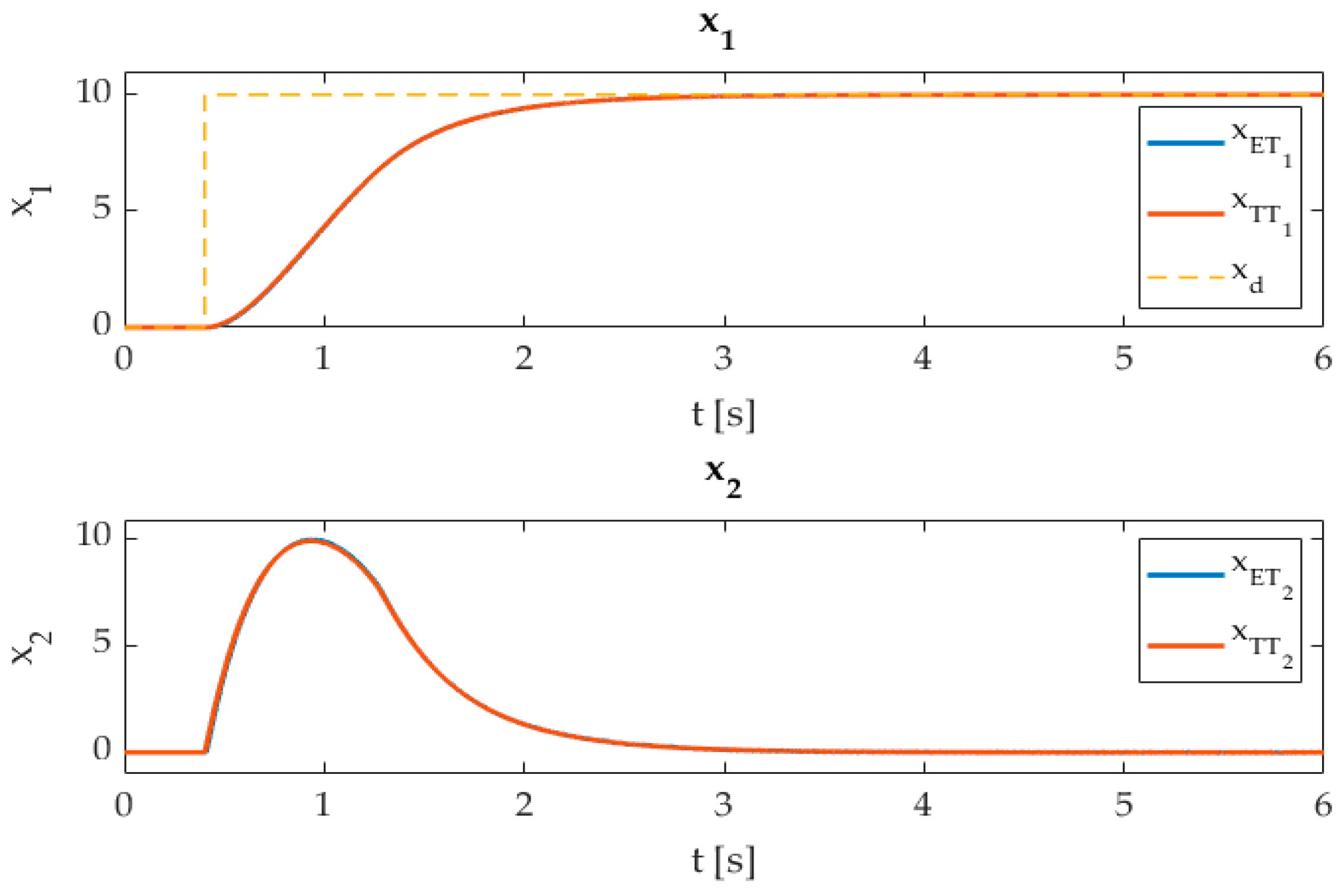
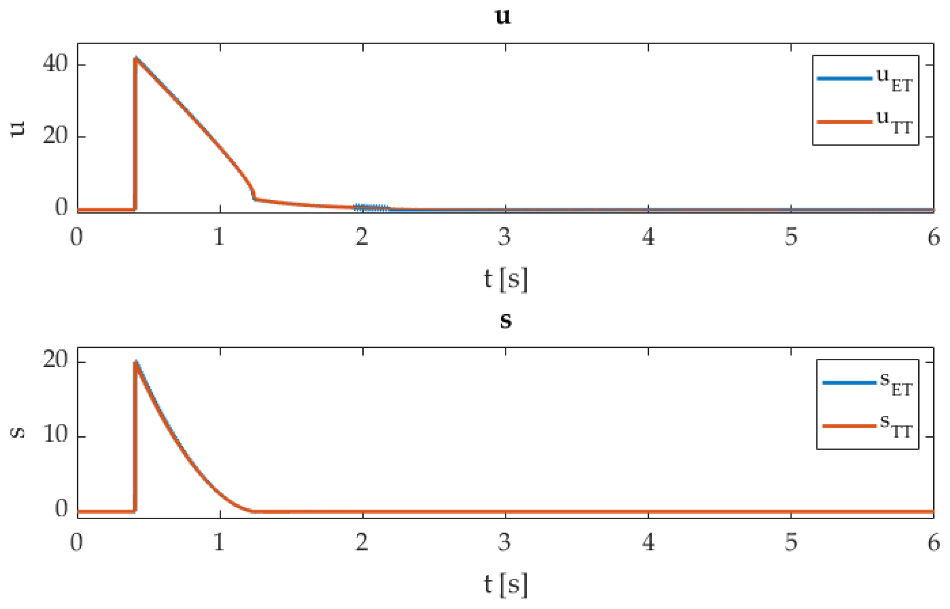
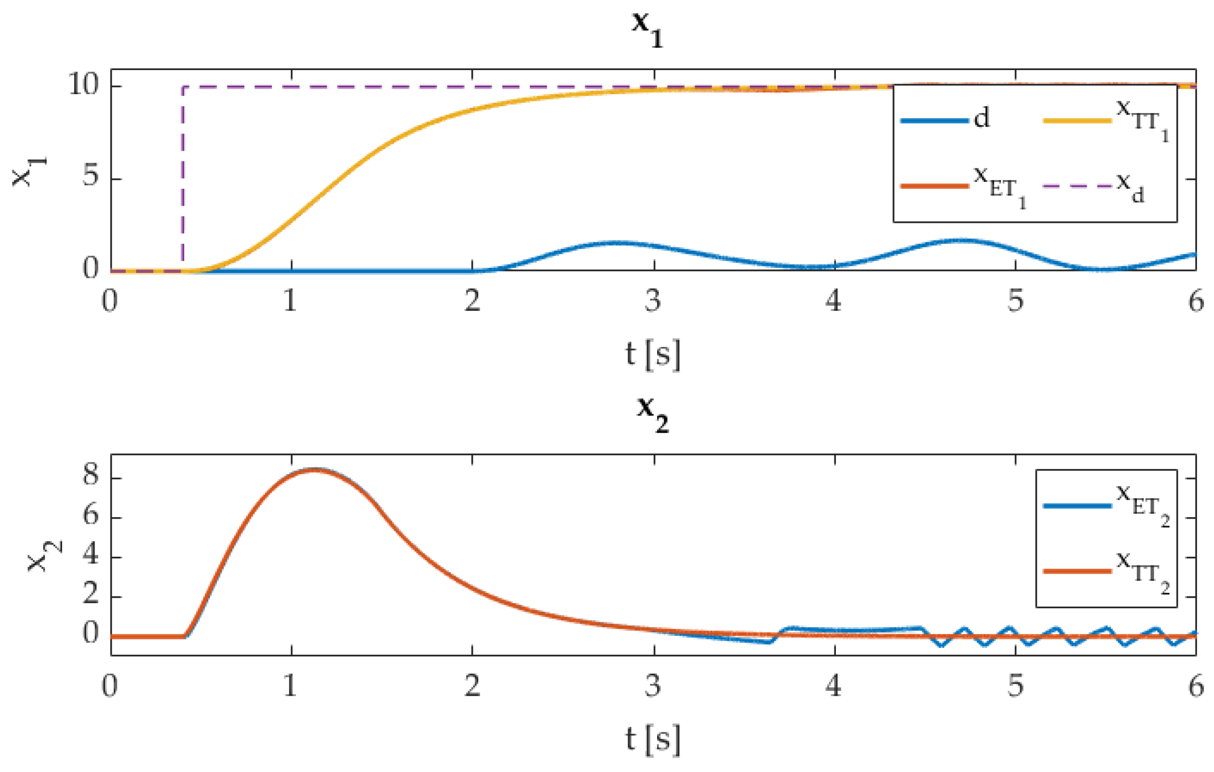
5. Controller Implementation and Comparison

For ET-SMC validation, the second-order system is selected as
x ˙ 1 ( t ) = x 2 ( t ) x ˙ 2 ( t ) = 2.715 f u ( t ) x 2 ( t ) 1.24 u ( t ) + d ( t ) ,
where the vector state  x ( t )  is given as  x ( t ) = x d ( t ) x ( t ) x d ( t )  is a known variable.  f u ( t )  is a nonlinear function given as
f u ( t ) = u ( t ) + η n s i g n u ( t ) i f u ( t ) > η n 0 i f u ( t ) η n u ( t ) η n s i g n u ( t ) i f u ( t ) < η n ,
where  η n = 0.23 . The disturbance parameters according to Assumption 3 are  Δ d = 1.9  and  ξ d = 1.7 . The controller parameters (11) with consideration of conditions (12) and (13) are given in Table 1.
The effectiveness of the ET-SMC approach is verified in the HIL system. The HIL system is composed of a MATLAB/Simulink environment with an embedded system based on the STM32 AMRF7xx (ARM32) architecture; a similar approach is presented [54]. The simulation environment and embedded system are connected over the TCP/IP protocol, with a measured network latency of approx.  < 0.98   ms . The plant and triggering policy are implemented in the simulated environment, where the controller (11) is embedded in the ARM32. The communication protocol over TCP/IP uses a fixed message length of the 250 B/package. When the triggering occurs, the system states are transmitted to the ARM32. The inter-event time is measured on the embedded system. The solver step of the HIL system is set to  1   ms  and  min T i > 17   ms  according to the preselected triggering condition  β . Error is calculated as  e = x 1 ( t ) x 1 ( t i ) 2 + x 2 ( t ) x 2 ( t i ) 2 . The performance of the ET-STA and TT-STA (TT-time triggering) implementation is verified with the following indices,
R M S w = 1 n s k = 1 n s w k 2 , w x 1 , s , u T T , u E T ,
F l a g u = i = 0 n s n i , n i = 0 f o r u e t β 1 f o r u e t > β ,
where  n i n s  are triggering instants and the number of triggering events, respectively, and  n s > 0  holds. The average inter-event time  T i  during the controller operation is measured as
T ¯ i = 1 n i i = 1 n i T i
The ET-STA is compared to the TT-STA with a fixed sampling time of  T s = 1 ms . Figure 1 shows a comparison of the ET-STA and TT-STA implementation techniques.
The controller outputs and sliding variables are presented in Figure 2.
Figure 3 presents the error function  e  with a triggering condition  β  and the controller’s flags of the ET/TT approach. Figure 4 presents a detailed view of the triggering events.
The index values (46)–(48) are presented in Table 2. The RMS value is measured from time 2.5 s after the transient response.
Figure 1, Figure 2, Figure 3 and Figure 4 present the efficiency of the ET implementation methodology. The given experiments confirm the expected results. The dynamic performance was not affected by the ET execution policy, and there was practically no deviation from the TT technique. The main difference can be noticed in the number of execution flags, in Figure 3 and Figure 4. It is evident that the ET approach reduces the computation burden of the controller drastically, where almost no updates are required, when the sliding variable  s  reaches the sliding manifold; see Figure 3 and Table 2—flag percent. The next update will happen regarding the boundaries (35) and (36), where the next inter-event time  T i  is related closely to the closed-loop system dynamic and triggering bound  β . In contrast to the TT approach, it is evident that  T i T s . The tracking accuracy of the ET-STA is due to the triggering bound  β  being reduced, which can be reviewed in Table 2 with RMS measurements for state  x 1  and  s .
The following results were conducted with the added disturbance  d ( t ) = 0.7 sin 3.5 t + 0.14 sin 5.8 t + 0.12 . Figure 5, Figure 6 and Figure 7 present a robustness comparison of the ET-STA and TT-STA techniques.
The indices (46)–(48) with added disturbance  d  are presented in Table 3.
The added disturbance experiment shows that the closed-loop system’s robustness was preserved regarding both techniques. The ET-STA has a significant deviation in the controller output  u E T , where the disturbance dynamics trigger ET-STA at the level and consequently produce the stable alternating output. Such a low-frequency signal  u E T  is not harmful to the system input as a high-frequency chattering result of the fast TT execution technique. The difference among states’  x 1  RMS values in Table 3 and Figure 5 is insignificant and confirms that the tracking capability and closed-loop performance were not disturbed much. The known sliding mode performance of the STA was preserved with the ET-STA approach.

6. Conclusions

The paper confirms that the event-triggered STA is a reliable real-time controller execution approach. It has been acknowledged that the SMC properties have not deteriorated, and all the system performance was preserved. Additionally, event-triggered STA lowers the computational burden drastically, confirmed by the experiments, and can be used as a system relaxation technique or in the network control system, where the network traffic impacts the system performance and stability significantly. For the latter, the network traffic can be scheduled according to the knowledge of the minimal and average inter-event time. The triggering bound and STA controller parameters affect the system accuracy performance and computational complexity significantly. With proper selection of the controller parameters, the sliding mode performance is preserved, and the chattering phenomena can be mitigated effectively. The crucial role of the stability analysis is the ISS properties, whereby the triggering policy is derived upon the error function, and the practical sliding mode is established. All the system states are ultimately bounded, and the stability of the ET-STA is ensured.
Further improvement of the ET-STA operation can be achieved by analyzing the reaching phase period, where the system states’ attraction to the prescribed sliding variable introduces a positive invariant set, where the initial value of the system and the proper controller action guide the system variables to the prescribed region with minimal controller action in the transient response.

Author Contributions

Conceptualization, A.S.; methodology, D.G. and A.S.; software, A.S.; validation, D.G.; formal analysis, A.S. and D.G.; investigation, A.S. and D.G.; writing—original draft preparation, A.S.; writing—review and editing, D.G.; visualization, A.S.; supervision, D.G.; funding acquisition, D.G. All authors have read and agreed to the published version of the manuscript.

Funding

This research was funded by the Slovenian Research Agency (ARRS) grant number P2-0065.

Conflicts of Interest

The authors declare no conflict of interest.

References

  1. Proakis, J.G.; Manolakis, D.G. Digital Signal Processing: Principles, Algorithms, and Applcations; Prentice Hall: Hoboken, NJ, USA, 2007. [Google Scholar]
  2. Phillips, C.L.; Nagle, H.T.; Chakrabortty, A. Digital Control System Analysis and Design; Pearson: London, UK, 2015. [Google Scholar]
  3. Jetto, L.; Orsini, V. A new event-driven output-based discrete-time control for the sporadic MIMO tracking problem. Int. J. Robust Nonlinear Control 2014, 24, 859–875. [Google Scholar] [CrossRef]
  4. Khashooei, B.; Antunes, D.; Heemels, W. Output-based event-triggered control with performance guarantees. IEEE Trans. Autom. Control 2017, 62, 3646–3652. [Google Scholar] [CrossRef]
  5. Astrom, K.; Bernhardsson, B. Comparison of periodic and event based sampling for first-order stochastic systems. In Proceedings of the 14th IFAC World Congress (1999), Beijing, China, 5–9 July 1999; Volume 11, pp. 301–306. [Google Scholar]
  6. Antunes, D.; Heemels, W.P.M.H. Rollout event-triggered control: Beyond periodic control performance. IEEE Trans. Autom. Control 2014, 59, 3296–3311. [Google Scholar] [CrossRef]
  7. Mazo, M.; Tabuada, P. Decentralized event-triggered control over wireless sensor/actuator networks. IEEE Trans. Autom. Control 2011, 56, 2456–2461. [Google Scholar] [CrossRef]
  8. Khojasteh, M.J.; Tallapragada, P.; Cortés, J.; Franceschetti, M. Time-triggering versus event-triggering control over communication channels. In Proceedings of the 2017 IEEE 56th Annual Conference on Decision and Control (CDC), Melbourne, VIC, Australia, 12–15 December 2017; pp. 5432–5437. [Google Scholar]
  9. Tallapragada, P.; Cortés, J. Event-triggered stabilization of linear systems under bounded bit rates. IEEE Trans. Autom. Control 2016, 61, 1575–1589. [Google Scholar] [CrossRef]
  10. Sawant, V.; Chakraborty, D.; Pal, D. Intermittent Feedback Control with Maximum Average Off-Time. IEEE Trans. Autom. Control 2021, 66, 5013–5020. [Google Scholar] [CrossRef]
  11. Bai, Q.; Wei, Z. Event-Triggered Impulsive Optimal Control for Continuous-Time Dynamic Systems with Input Time-Delay. Mathematics 2022, 10, 279. [Google Scholar] [CrossRef]
  12. Adaldo, A.; Alderisio, F.; Liuzza, D.; Shi, G.; Dimarogonas, D.V.; Di Bernardo, M.; Johansson, K.H. Event-triggered pinning control of switching networks. IEEE Trans. Control Netw. Syst. 2015, 2, 204–213. [Google Scholar] [CrossRef]
  13. Ge, X.; Han, Q.-L.; Zhang, X.-M.; Ding, L.; Yang, F. Distributed Event-Triggered Estimation Over Sensor Networks: A Survey. IEEE Trans. Cybern. 2020, 50, 1306–1320. [Google Scholar] [CrossRef]
  14. Nandanwar, A.; Dhar, N.K.; Malyshev, D.; Rybak, L.; Behera, L. Stochastic Event-Based Super-Twisting Formation Control for Multiagent System Under Network Uncertainties. IEEE Trans. Control Netw. Syst. 2022, 9, 966–978. [Google Scholar] [CrossRef]
  15. Ruiz, A.; Jimenez, J.E.; Sanchez, J.; Dormido, S. A practical tuning methodology for event-based P.I. control. J. Process Control 2014, 24, 278–295. [Google Scholar] [CrossRef]
  16. Arz’en, K.E. A simple event-based PID controller. IFAC Proc. Vol. 1999, 32, 8687–8692. [Google Scholar] [CrossRef]
  17. Du, S.; Yan, Q.; Qiao, J. Event-Triggered P.I.D. Control for Wastewater Treatment Plants. Water Process Eng. 2020, 38, 101659. [Google Scholar]
  18. Durand, S.; Boisseau, B.; Marchand, N.; Guerrero-Castellanos, J. Event-Based P.I.D. Control: Application to a Mini QuadrotorHelicopter. J. Control Eng. Appl. Inform. 2018, 20, 36–47. [Google Scholar]
  19. Heemels, W.; Sandee, J.; van den Bosch, P. Analysis of event-driven controllers for linear systems. Int. J. Control 2009, 81, 571–590. [Google Scholar] [CrossRef]
  20. Heemels, W.P.M.H.; Johansson, K.H.; Tabuada, P. An introduction to event-triggered and self-triggered control. In Proceedings of the 2012 IEEE 51st IEEE Conference on Decision and Control (CDC), Maui, HI, USA, 10–13 December 2012; pp. 3270–3285. [Google Scholar] [CrossRef]
  21. Brunner, F.D.; Heemels, W.P.M.H.; Allgöwer, F. Event-triggered and self-triggered control for linear systems based on reachable sets. Automatica 2019, 101, 15–26. [Google Scholar] [CrossRef]
  22. Lehmann, D.; Henriksson, E.; Johansson, K.H. Event-triggered model predictive control of discrete-time linear systems subject to disturbances. In Proceedings of the 2013 European Control Conference (ECC), Zurich, Switzerland, 17–19 July 2013; pp. 1156–1161. [Google Scholar]
  23. Hashimoto, K.; Adachi, S.; Dimarogonas, D.V. Self-triggered model predictive control for nonlinear input-affine dynamical systems via adaptive control samples selection. IEEE Trans. Autom. Control 2017, 62, 177–189. [Google Scholar] [CrossRef]
  24. Xu, Z.; He, L.; He, N.; Bai, B. A quasi-differential type event-triggered model predictive control for perturbed continuous linear systems with constraints. IET Control Theory Appl. 2021, 15, 2334–2343. [Google Scholar] [CrossRef]
  25. He, N.; Du, J.; Xu, Z.; Chen, J. Event-triggered M.P.C. for linear systems with bounded disturbances: An accumulated error based approach. IET Control Theory Appl. 2022, 16, 816–827. [Google Scholar] [CrossRef]
  26. Xu, B.; Li, B. Event-Triggered State Estimation for Fractional-Order Neural Networks. Mathematics 2022, 10, 325. [Google Scholar] [CrossRef]
  27. Liu, L.; Li, X.; Liu, Y.-J.; Tong, S. Neural Network Based Adaptive Event Trigger Control for a Class of Electromagnetic Suspension Systems. Control. Eng. Pract. 2021, 106, 104675. [Google Scholar] [CrossRef]
  28. Cheng, J.; Liang, L.; Park, J.H.; Yan, H.; Li, K. A dynamic event-triggered approach to state estimation for switched memristive neural networks with nonhomogeneous sojourn probabilities. IEEE Trans. Circuits Syst. 2021, 68, 4924–4934. [Google Scholar] [CrossRef]
  29. Wang, X.; Fei, Z.; Yu, J.; Du, Z. Passivity-based event-triggered fault tolerant control for VTOL with actuator failure and parameter uncertainties. Int. J. Syst. Sci. 2019, 50, 817–828. [Google Scholar] [CrossRef]
  30. Fei, Z.; Guan, C.; Gao, H. Exponential synchronization of networked chaotic delayed neural network by a hybrid event trigger scheme. IEEE Trans. Neur. Net. Learn. Syst. 2018, 29, 2558–2567. [Google Scholar] [CrossRef] [PubMed]
  31. Wu, W.; Reimann, S.; Gorges, D.; Liu, S. Suboptimal event-triggered control for time-delayed linear systems. IEEE Trans. Autom. Control 2015, 60, 1386–1391. [Google Scholar] [CrossRef]
  32. Behera, A.K.; Bandyopadhyay, B.; Cucuzzella, M.; Ferrara, A.; Yu, X. A survey on event-triggered sliding mode control. IEEE J. Emerg. Sel. Top. Ind. Electron. 2021, 2, 206–217. [Google Scholar] [CrossRef]
  33. Behera, A.K.; Bandyopadhyay, B.; Yu, X. Periodic event-triggered sliding mode. Automatica 2018, 96, 1916–1931. [Google Scholar] [CrossRef]
  34. Incremona, P.G.; Ferrara, A. Adaptive model-based event-triggered sliding mode control. Int. J. Adapt. Control Signal Process. 2016, 30, 1298–1316. [Google Scholar] [CrossRef]
  35. Tabuada, P. Event-triggered real-time scheduling of stabilizing control tasks. IEEE Trans. Autom. Control 2007, 52, 1680–1685. [Google Scholar] [CrossRef]
  36. Meng, Q.; Ma, Q.; Shi, Y. Fixed-Time Stabilization for Nonlinear Systems with Low-Order and High-Order Nonlinearities via Event-Triggered Control. IEEE Trans. Circuits Syst. I Regul. Pap. 2022, 69, 3006–3015. [Google Scholar] [CrossRef]
  37. Utkin, V.I.; Poznyak, A.S. Adaptive sliding mode control with application to super-twist algorithm: Equivalent control method. Automatica 2013, 49, 39–47. [Google Scholar] [CrossRef]
  38. Moreno, J.A.; Osorio, M. A Lyapunov approach to second-order sliding mode controllers and observers. In Proceedings of the 2008 47th IEEE Conference on Decision and Control, Camcum, Mexico, 9–11 December 2008; pp. 2856–2861. [Google Scholar]
  39. Shtessel, Y.; Edwards, C.; Fridman, L.; Levant, A. Sliding Mode Control and Observation; Springer: New York, NY, USA, 2014. [Google Scholar]
  40. Tseng, M.L.; Chen, M.S. Chattering reduction of sliding mode control by low-pass filtering the control signal. Asian J. Control 2010, 12, 392–398. [Google Scholar] [CrossRef]
  41. Zhang, J.; Youngkai, L.; Shijie, G.; Chengshan, H. Control Technology of Ground-Based Laser Communication Servo Turntable via a Novel Digital Sliding Mode Controller. Appl. Sci. 2019, 9, 4051. [Google Scholar] [CrossRef]
  42. Utkin, V. Discussion aspects of high-order sliding mode control. IEEE Trans. Autom. Control 2016, 61, 829–833. [Google Scholar] [CrossRef]
  43. Ventura, U.P.; Fridman, L. When is it reasonable to implement the discontinuous sliding-mode controllers instead of the continuous ones? Frequency domain criteria. Int. J. Robust Nonlinear Control 2019, 29, 810–828. [Google Scholar] [CrossRef]
  44. Boiko, I.; Fridman, L. Analysis of chattering in continuous sliding mode controllers. IEEE Trans. Autom. Control 2005, 50, 1442–1446. [Google Scholar] [CrossRef]
  45. Ventura, U.P.; Fridman, L. Chattering measurement in SMC and HOSMC. In Proceedings of the 2016 14th International Workshop on Variable Structure Systems, Nanjing, China, 1–4 June 2016; pp. 108–113. [Google Scholar] [CrossRef]
  46. Chalanga, A.; Kamal, S.; Fridman, L.; Bandyopadhyay, B.; Moreno, J.A. Implementation of super-twisting control: Super-twisting and higher order sliding-mode observer-based approaches. IEEE Trans. Ind. Electron. 2016, 63, 3677–3685. [Google Scholar] [CrossRef]
  47. Brogliato, B.; Polyakov, A. Digital implementation of sliding-mode control via the implicit method: A tutorial. Int. J. Robust Nonlinear Control 2021, 31, 3528–3586. [Google Scholar] [CrossRef]
  48. Obeid, H.; Fridman, L.; Laghrouche, S.; Harmouche, M.; Golkani, M.A. Adaptation of Levant’s differentiator based on barrier function. Int. J. Control 2018, 91, 2019–2027. [Google Scholar] [CrossRef]
  49. Sarjaš, A.; Gleich, D. Toward Embedded System Resources Relaxation Based on the Event-Triggered Feedback Control Approach. Mathematics 2022, 10, 550. [Google Scholar] [CrossRef]
  50. Benyazid, Y.; Fnadi, M.; Nouri, A.S. A Discrete Integral Sliding Manifold for a Nonlinear System with Time Delay: An Event-Triggered Scheme. Mathematics 2023, 11, 2326. [Google Scholar] [CrossRef]
  51. Behera, A.K.; Bandyopadhyay, B. Event-triggered sliding mode control for a class of nonlinear systems. Int. J. Control 2016, 89, 1916–1931. [Google Scholar] [CrossRef]
  52. Sontag, E.D.; Wang, Y. New characterizations ofinput-to-state stability. IEEE Trans. Autom. Control 1996, 41, 1283–1294. [Google Scholar] [CrossRef]
  53. Ventura, U.P.; Fridman, L. Design of super-twisting control gains: A describing function based methodology. Automatic 2019, 99, 175–180. [Google Scholar] [CrossRef]
  54. Alonge, F.; D’ippolito, F.; Garraffa, G.; Giaconia, G.C.; Latona, R.; Sferlazza, A. Sliding Mode Control of Quadratic Boost Converters Based on Min-Type Control Strategy. IEEE Access 2023, 11, 39176–39184. [Google Scholar] [CrossRef]
Figure 1. The comparison of ET and TT techniques, with variables  x 1 , x2, and xd.
Mathematics 11 04314 g001
Figure 2. Controller outputs  u E T , uTT, with sliding variables sET and sTT.
Mathematics 11 04314 g002
Figure 3. Error function  e  with triggering bound β and controllers update flags for the ET and TT techniques.
Mathematics 11 04314 g003
Figure 4. Detailed view of the ET-STA events with error function  e  and triggering bound β.
Mathematics 11 04314 g004
Figure 5. The ET-STA and TT-STA closed-loop responses of variables  x 1 , x2, xd with added disturbance d.
Mathematics 11 04314 g005
Figure 6. The ET-STA and TT-STA closed-loop responses of variables  u E T , uTT, sET, sTT with added disturbance d.
Mathematics 11 04314 g006
Figure 7. The ET-STA and TT-STA controllers update activity with the evolution of the variable  e  with added disturbance d.
Mathematics 11 04314 g007
Table 1. ET-STA controller parameters.
  Parameters   k 1   , k 2   , c   , β
  k 1 9.71
  k 2 4.33
  c 2.78
  β 0.212
Table 2. Performance indices of the ET-STA and TT-STA controllers.
Controller RMS x 1 RMSuRMSsminTimaxTimeanTiFlag
ET-STA0.08590.00685.2 × 10−318.2 ms38.6 s13.2 s3.9%
TT-STA0.01560.07123.7 × 10−51 ms1 ms1 ms100%
Table 3. Performance indices of the ET-STA and TT-STA controllers.
Controller RMS x 1 RMSuRMSsminTimaxTimeanTiFlag
ET-STA0.1022.710.158113.3 ms12.4 s1.67 s23.7%
TT-STA0.0870.70714.9 × 10−41 ms1 ms1 ms100%
Disclaimer/Publisher’s Note: The statements, opinions and data contained in all publications are solely those of the individual author(s) and contributor(s) and not of MDPI and/or the editor(s). MDPI and/or the editor(s) disclaim responsibility for any injury to people or property resulting from any ideas, methods, instructions or products referred to in the content.

