Article

Adaptive Finite-Time Fuzzy Control for Uncertain Nonlinear Systems with Asymmetric Full-State Constraints

1
School of Automation, Xi’an University of Posts and Telecommunications, Xi’an 710072, China
2
Xi’an Key Laboratory of Advanced Control and Intelligent Process, Xi’an 710072, China
*
Author to whom correspondence should be addressed.
Mathematics 2023, 11(20), 4313; https://doi.org/10.3390/math11204313
Submission received: 1 October 2023 / Revised: 10 October 2023 / Accepted: 12 October 2023 / Published: 16 October 2023

Abstract

:
This paper studies the adaptive finite-time fuzzy control issue associated with uncertain nonlinear systems that exhibit asymmetric constraints on the full state. A distinct function, constrained by nonlinear states, is designed to mitigate the excessive breach of these full-state boundaries. Unlike the standard barrier Lyapunov function (BLF) method, this approach solves symmetric and asymmetric full-state constraints without modifying the controller structure, and it does not require any additional assumptions about virtual control to be met. Simultaneously employing approximating functions using fuzzy logic systems and incorporating dynamic surface control technology integrated with a first-order filter, the unknown nonlinear functions emanating from the suggested controller strategy are estimated. Additionally, this approach addresses the prevalent problem of complexity explosion observed in conventional backstepping techniques. An adaptive finite-time fuzzy tracking control strategy is introduced, ensuring that all signals and tracking errors of the controlled system remain bounded in finite time. Finally, two simulation examples are given to illustrate the effectiveness of the proposed control scheme, confirming that all states remain within the predefined regions.

1. Introduction

The method of backstepping, since its introduction in 1991 by Kanellakopouls, has become a frequently used approach in designing control strategies for systems characterized by nonlinear dynamic models [1,2,3]. It has significantly contributed to the development of systems with multi-input and multi-output (MIMO) characteristics as well as those with single-input and single-output (SISO) features [4,5,6,7,8]. However, the backstepping method proves inadequate when dealing with nonlinear systems of incomplete knowledge. Consequently, in recent years, scholars have extensively employed neural networks (NNs) in conjunction with fuzzy logic systems (FLSs) to tackle these model uncertainties, leveraging their superior approximation capabilities [9,10,11]. Furthermore, the integration of adaptive NNs or adaptive FLSs with backstepping techniques for control problems has spawned a wealth of research, thanks to their systematic and structured controller design benefits [12,13,14,15]. It is essential to note that employing the conventional backstepping approach may induce an “explosion of complexity” resulting from the continuously differentiating simulated control inputs, potentially escalating the online computation load or potentially diminishing the efficacy of control. Dynamic surface control technology offers a viable remedy for this challenge [16]. Recent studies have documented adaptive control mechanisms utilizing the technology of dynamic surface control designed for systems with nonlinear uncertainties [17,18]. However, these designs of adaptive backstepping controllers overlook the constraints of the controlled systems. In practice, constraints manifest in various forms such as full-state constraints, dead zero, input saturation, and input–output state constraints, owing to performance constraints, physical boundaries, and security issues in numerous engineering systems. These constraints present new challenges for system control [16,19,20,21,22,23].
The issue of constraint management in systems has attracted considerable research interest, with various nonlinear systems being explored through diverse methods including the barrier Lyapunov function (BLF) and predictive-model-based control [24,25,26]. The BLF has emerged as a widely used technique for addressing constraint-related challenges, with a significant body of research exploring controller design and stability analysis based on this approach. Investigations of BLF-based backstepping control have predominantly focused on both symmetric and asymmetric constraints within full-state nonlinear systems. However, the application of the BLF to asymmetric full-state constraints can lead to discontinuous phenomena [27,28]. Regardless of whether the constraints are symmetric or asymmetric, when utilizing the BLF method in the backstepping controller’s design process, it is presumed that the virtual controller is confined to a defined region. This assumption often complicates the control scheme design due to the necessity of offline parameter calculations. To overcome this limitation, the introduction of nonlinear transformations or functions dependent on state aims to address state constraint issues [29,30]. Despite these advancements, the majority of current research on state constraint control only confirm the asymptotic stability of the resultant system [31,32].
For tracking control problems in nonlinear systems, a swift convergence rate is critically essential. Control methods with asymptotic properties achieve the targeted performance as the time of convergence approaches infinity. However, finite-time control approaches tend to outperform these methods by providing superior disturbance-rejection capability, enhanced tracking accuracy, and quicker convergence rates. Moreover, they guarantee the realization of control objectives within a finite time, underscoring their significance. Consequently, considerable investigation has been carried out concerning the use of finite-time control techniques in intricate industrial setups, encompassing high-end automobiles, nuclear energy facilities, and aviation systems [6,33,34,35]. However, based on our understanding, no study currently exists that addresses utilizing the dynamic surface control method for uncertain systems with nonlinear properties that demonstrate full-state constraints to manage the inherent ”explosion of complexity” dilemma found in the literature pertaining to the control within a finite-time frame sector.
Motivated by the observations mentioned earlier, this study presents a new adaptive strategy for fuzzy control within a finite-time frame designed for nonlinear systems with uncertainties, especially when faced with communication limitations and comprehensive state constraints: (1) Unlike the BLF-based method [24,25,26], our approach utilizing the nonlinear state-constrained function can handle symmetric as well as asymmetric constraints on the full state without modifying the controller structure, obviating the need for the presumption that the virtual controller should remain within a predetermined area. (2) In contrast to recent studies on full-state-constrained control employing the nonlinear state-constrained function, which primarily asserts that the closed-loop systems remain bounded as referenced in [29,36], this paper introduces a novel finite-time control approach using the same function. This approach is devised to handle systems characterized by nonlinear uncertainties to guarantee that the tracking error remains within bounds in a finite time, without violating the full-state constraints. (3) To prevent the “explosion of complexity” issue intrinsic to the traditional backstepping methodology, this research incorporates the dynamic surface control technique, utilizing a first-order filter, into the controller’s design.
The article continues as described below. Section 2 delineates the problem definition and accompanying preliminaries. Subsequently, Section 3 delves into the primary findings. Section 4 demonstrates illustrative examples to substantiate the main results. The paper culminates in Section 5 with a conclusion.
Notations: R m × n represents the collection of real matrices of dimension m × n . C p signifies a function equipped with p successive derivatives, and · is used to represent the norm derived from Euclidean space.

2. Problem Statement and Preliminaries
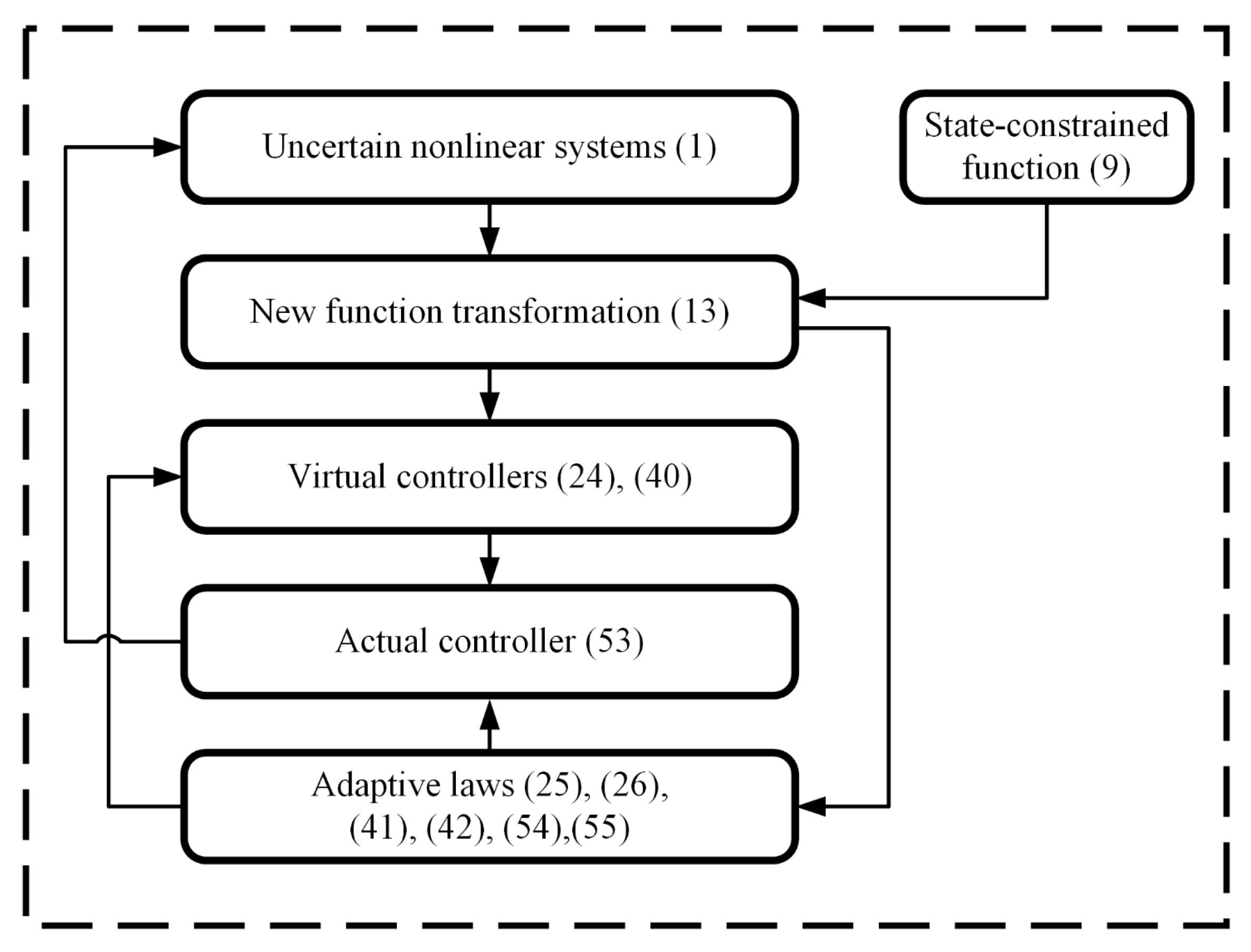
In this article, the nonstrict feedback uncertain nonlinear systems are considered
x ˙ i = f i ( x ) + x i + 1 , 1 i n 1 x ˙ n = f n ( x ) + u y = x 1
where x = [ x 1 , , x n ] T R n , u R , y R represent the system’s plant state vector, the control input, and the system output, respectively. Furthermore f i ( x ) R , i = 1 , , n are unknown C 1 nonlinear functions. It is postulated that region constraint Θ i = { x i | σ ̲ i < x i < σ ¯ i } is applied to x i .
Control objective:
(1) The system’s resultant output denoted as y can align with the target signal y d within a finite time;
(2) All signals in the evolved systems remain confined within a finite time;
(3) All states x i adhere to the preestablished region constraint, i.e., x i ( t ) Θ i , for t > 0 , 1 i n .
For the design of the control strategy, an assumption and a set of lemmas are provided.
Lemma 1
([37]). Given positive numbers s > 0 , g > 0 , and k > 0 , it holds
| z | s | x | g s k s + g | z | s + g + g k s / g s + g | x | s + g
Lemma 2
([38]). (Regarding Young’s Inequality) Given that x and y both belong to R, it follows that
x y p w w | x | w + p e p e | y | e
where p > 0 , w > 1 , e > 1 , and ( w 1 ) ( e 1 ) = 1 .
Lemma 3
([39]). In considering the nonlinear dynamical system represented by z ˙ = f ( z ) , and assuming a smooth Lyapunov function V ( z ) that is positive definite with scaling factors where b is positive, σ lies between 0 and 1, and μ exceeds zero, it follows that
V ˙ ( z ) b V ( z ) σ + μ , t > 0
Under these conditions, the system x ˙ = f ( x ) can be described as semiglobal practical finite-time stable (SGPFS).
Assumption 1.
The target signal y d , along with its n-order derivatives, remain continuously constrained. In addition, it is stipulated that y d satisfies the condition | y ˙ d ( t ) | y ¯ ¯ d , | y d ( t ) | y ¯ d , and σ ̲ 1 < y d ( t ) < σ ¯ 1 , where y ¯ ¯ d , y ¯ d , σ ̲ 1 and σ ¯ 1 are positive constants.
Regarding the unknown function f ( x ) , the radial foundation function of a FLS is utilized for approximation, resulting in
f ( x ) = θ T φ ( x )
where x represents the input vector, θ = [ μ ¯ 1 , μ 2 , , μ l ] T represents the weight vector, with l denoting the count of FLS nodes, and φ ( x ) = [ μ ¯ 1 ( x ) , μ ¯ 2 ( x ) , , μ ¯ l ( x ) ] T symbolizes the radial foundation function
μ ¯ i ( x ) = exp ( 1 2 b ¯ 2 x v i 2 ) , 1 i l
where v i refers to the kernel function’s core and b ¯ represents the parameter of width.
Lemma 4
([40]). Should f ( x ) be a continuous mathematical operation delineated on the finite collection A, there is an Equation (5) that satisfies the subsequent inequality for a specified positive value ς > 0
sup x A | f ( x ) θ * T φ ( x ) | ς
where θ * represents the best parameter vector.
Lemma 5
([41]). Consider φ ( x ) as the vector representation of basis functions given by φ ( x ) = [ μ ¯ 1 ( x ) , μ ¯ 2 ( x ) , , μ ¯ l ( x ) ] T from Equation (5). Additionally, let x be denoted by x = [ x 1 , x 2 , , x n ] T , representing the vector designated for input. Consequently, for an integer m that is positive with m n , the subsequent inequality can be established
φ ( x ) 2 φ ( x ¯ m ) 2
where x ¯ m = [ x 1 , x 2 , , x m ] T .

3. Main Results

Within this segment, an adaptive finite-time fuzzy controller is proposed, designed for a full-state-constrained nonlinear system with uncertainties. This design leverages the approach of dynamic surfacing combined with a first-order filter and the backstepping technique.

3.1. State-Constrained Function

To guarantee the preservation of full-state constraints, the subsequent state-bounded function is presented.
χ i ( t ) = ϱ i ( σ ¯ i + σ ̲ i ) 2 x i ( t ) ( σ ̲ i + x i ( t ) ) ( σ ¯ i x i ( t ) ) , i = 1 , 2 , , n
where x i ( 0 ) Θ i , i = 1 , , n , ϱ i represents a positive constant. It can be seen that as x i ( t ) nears the edge of the set Ψ i , i.e., x ( t ) approaches x ( t ) σ ¯ i or x ( t ) σ ̲ i , then χ i ( t ) tends to infinity, i.e., χ i ( t ) ± . Consequently, full-state constraints are preserved if, and only if, χ i ( t ) remains bounded.
Based on (9), one has
χ ˙ i ( t ) = ϖ i x ˙ i ( t ) , i = 1 , 2 , , n
where
ϖ i = ϱ i ( σ ¯ i + σ ̲ i ) 2 ( σ ¯ i σ ̲ i + x i 2 ( t ) ) ( σ ̲ i + x i ( t ) ) 2 ( σ ¯ i x i ( t ) ) 2
Moreover, it is given that x i ( t ) = γ i χ i ( t ) , i = 1 , 2 , , n
γ i = ( σ ̲ i + x i ( t ) ) ( σ ¯ i x i ( t ) ) ϱ i ( σ ¯ i + σ ̲ i ) 2
Remark 1.
If σ ̲ i = σ ¯ i , it indicates that the nonlinear state-constrained function is capable of addressing symmetric full-state constraint issues. Therefore, this function can be applied to both symmetric and asymmetric full-state constraints. Importantly, when dealing with asymmetric full-state constraint systems, the function circumvents the discontinuity often encountered in the BLF-based method.
Remark 2.
Traditional BLF-based approaches are primarily designed to obtain constrained tracking errors directly. To adhere to state constraints, a subsequent conversion of errors into states is a requisite. However, from the definition of χ i ( t ) , the proof needs to demonstrate that χ i ( t ) is bounded, and the constraint of σ ̲ i < x i ( t ) < σ ¯ i can be ensured.

3.2. Adaptive Finite-Time Fuzzy Controller

Prior to devising the control strategy, a sequence of innovative function conversions is delineated
z 1 = χ 1 1 z i = χ i i ρ i = i ϑ i 1 , i = 2 , , n
where 1 = ϱ 1 ( σ ¯ 1 + σ ̲ 1 ) 2 y d ( t ) ( σ ̲ 1 + y d ( t ) ) ( σ ¯ 1 y d ( t ) ) , and i represents the signal released from the ensuing first-order filter, characterized by
ι i ˙ i + i = ϑ i 1 , i = 2 , , n
where ϑ i 1 represents the virtual controller, while ι i stands as a positive constant.
Remark 3.
It is commonly recognized that the “explosion of complexity" can arise from the continuous differentiation termed ϑ i 1 within the backstepping technique. This paper leverages the technique of dynamic surface control, specifically the first-order filter as outlined in Equation (14), to address this issue. The signal i without a surge in terms, using virtual control signal ϑ i 1 as input, is further employed in the control scheme design. Consequently, the risk of repetitive differentiation is effectively mitigated. A novel function transformation, defined as z i = χ i i is established using the first-order filter in conjunction with the backstepping approach to devise a finite-time tracking controller.
Step  i = 1 : Considering Equations (10) and (13), when differentiating z 1 in relation to the time variable, one has
z ˙ 1 = ϖ 1 ( f 1 ( x ) + γ 2 χ 2 ) ϖ d y ˙ d = ϖ 1 ( f 1 ( x ) + χ 2 + γ 2 χ 2 χ 2 ) ϖ d y ˙ d = ϖ 1 ( f 1 ( x ) + z 2 + ρ 2 + ϑ 1 + γ 2 χ 2 χ 2 ) ϖ d y ˙ d
where ˙ 1 = ϖ d y ˙ d and ϖ d = ϱ 1 ( κ ¯ 1 + k ̲ 1 ) 2 ( κ ¯ 1 k ̲ 1 + y d 2 ) ( k ̲ 1 + y d ( t ) ) 2 ( κ ¯ 1 y d ( t ) ) 2 .
Select the candidate for the Lyapunov function as
V 1 = 1 2 z 1 2 + 1 2 λ 11 θ ¯ ˜ 1 2 + 1 2 λ 12 ς ¯ ˜ 1 2 + 1 2 ρ 2 2
where ς ¯ ˜ 1 = ς ¯ 1 ς ¯ ^ 1 , θ ¯ ˜ 1 = θ ¯ 1 θ ¯ ^ 1 , ς ¯ ^ 1 and θ ¯ ^ 1 denote the approximations of θ ¯ 1 and ς ¯ 1 , respectively. Both λ 11 and λ 12 are positive design parameters. Definitions for θ ¯ 1 and ς ¯ 1 are provided subsequently. When differentiating Equation (16) in relation to the time variable, the result is
V ˙ 1 = z 1 z ˙ 1 + 1 λ 11 θ ¯ ˜ 1 θ ¯ ˜ ˙ 1 + 1 λ 12 ς ¯ ˜ 1 ς ¯ ˜ ˙ 1 + ρ 2 ρ ˙ 2
The term z 1 z ˙ 1 of (17) is described by
z 1 z ˙ 1 = z 1 ( ϖ 1 f 1 ( x ) + ϖ 1 z 2 + ϖ 1 ρ 2 + ϖ 1 ϑ 1 + ϖ 1 γ 2 χ 2 ϖ 1 χ 2 ) z 1 ϖ d y ˙ d
By using (13) and (18), (17) becomes
V ˙ 1 = z 1 ( ϖ 1 f 1 ( x ) + ϖ 1 z 2 + ϖ 1 ρ 2 + ϖ 1 ϑ 1 + ϖ 1 γ 2 χ 2 ϖ 1 χ 2 ) z 1 ϖ d y ˙ d + 1 λ 11 ς ¯ ˜ 1 ς ¯ ˜ ˙ 1 + 1 λ 12 θ ¯ ˜ 1 θ ¯ ˜ ˙ 1 + ρ 2 ρ ˙ 2
According to Lemma 2, it is obtained that
z 1 ϖ 1 ρ 2 1 2 z 1 2 ϖ 1 2 + 1 2 ρ 2 2
Let Ψ 1 ( x ) = ϖ 1 f 1 ( x ) + ϖ 1 γ 2 χ 2 ϖ 1 χ 2 . According to Lemma 4, the FLSs are implemented to estimate Ψ 1 ( x ) as follows
Ψ 1 ( x ) = φ 1 T ( x ) θ 1 * + ε 1
Given the bounded nature of ε 1 , a positive constant ς ¯ 1 exists, such that
| ε 1 | ς ¯ 1
It follows from (19)–(21) that
V ˙ 1 z 1 ( φ 1 T ( x ) θ 1 * + ε 1 + ϖ 1 z 2 + ϖ 1 ϑ 1 ) + 1 2 z 1 2 ϖ 1 2 + 1 2 ρ 2 2 z 1 ϖ d y ˙ d + 1 λ 11 ς ¯ ˜ 1 ς ¯ ˜ ˙ 1 + 1 λ 12 θ ¯ ˜ 1 θ ¯ ˜ ˙ 1 + ρ 2 ρ ˙ 2
Next, the virtual controller ϑ 1 is defined as
ϑ 1 = z 1 θ ¯ ^ 1 2 ϖ 1 ( | z 1 | φ 1 T ( x 1 ) θ ¯ ^ 1 + ϵ 11 * ) z 1 ς ¯ ^ 1 2 ϖ 1 ( | z 1 | ς ¯ ^ 1 + ϵ 12 * ) + ϖ d y ˙ d ϖ 1 1 2 ϖ 1 sgn β ( z 1 ) 1 2 z 1 ϖ 1
θ ¯ ^ ˙ 1 = λ 11 θ ¯ ^ 1 + λ 11 | z 1 | φ 1 T ( x 1 )
ς ¯ ^ ˙ 1 = λ 12 ς ¯ ^ 1 + λ 12 | z 1 |
where sgn β ( z 1 ) = sign ( z 1 ) | z 1 | β , θ 1 * θ ¯ 1 , | ε 1 | ς ¯ 1 , ϵ 12 * = ϵ sign ( | z 1 | ς ¯ ^ 1 ) , ϵ 11 * = ϵ sign ( | z 1 | φ 1 T ( x 1 ) θ ¯ ^ 1 ) , 0 < β < 1 is the designed parameter, ϵ > 0 .
From Lemma 5 and by substituting Equations (24)–(26) into (23), it follows that
V ˙ 1 z 1 ( φ 1 T ( x ) θ 1 * + ε 1 + ϖ 1 z 2 z 1 θ ¯ ^ 1 2 | z 1 | φ 1 T ( x 1 ) θ ¯ ^ 1 + ϵ 11 * z 1 ς ¯ ^ 1 2 | z 1 | ς ¯ ^ 1 + ϵ 12 * 1 2 sgn β ( z 1 ) ) + 1 2 ρ 2 2 + 1 λ 11 ς ¯ ˜ 1 ς ¯ ˜ ˙ 1 + 1 λ 12 θ ¯ ˜ 1 θ ¯ ˜ ˙ 1 + ρ 2 ρ ˙ 2 | z 1 | φ 1 T ( x 1 ) θ ¯ 1 + | z 1 | | ε 1 | + ϖ 1 z 1 z 2 z 1 2 θ ¯ ^ 1 2 | z 1 | φ 1 T ( x 1 ) θ ¯ ^ 1 + ϵ 11 * z 1 2 ς ¯ ^ 1 2 | z 1 | ς ¯ ^ 1 + ϵ 12 * 1 2 sgn β + 1 ( z 1 ) + 1 2 ρ 2 2 + θ ¯ ˜ 1 θ ¯ ^ 1 θ ¯ ˜ 1 | z 1 | φ 1 T ( x 1 ) + ρ 2 ρ ˙ 2 + ς ¯ ˜ 1 ς ¯ ^ 1 ς ¯ ˜ 1 | z 1 | ϖ 1 z 1 z 2 1 2 sgn β + 1 ( z 1 ) + 1 2 ρ 2 2 + ς ¯ ˜ 1 ς ¯ ^ 1 + θ ¯ ˜ 1 θ ¯ ^ 1 + ρ 2 ρ ˙ 2 + 2 ϵ
Note that
| z 1 | φ 1 T ( x 1 ) θ ¯ 1 z 1 2 θ ¯ ^ 1 2 | z 1 | φ 1 T ( x 1 ) θ ¯ ^ 1 + ϵ 11 * θ ¯ ˜ 1 | z 1 | φ 1 T ( x 1 ) = | z 1 | φ 1 T θ ¯ ^ 1 ϵ 11 * | z 1 | φ 1 T ( x 1 ) θ ¯ ^ 1 + ϵ 11 * ϵ
| z 1 | | ε 1 | z 1 2 ς ¯ ^ 1 2 | z 1 | ς ¯ ^ 1 + ϵ 12 * ς ¯ ˜ 1 | z 1 | z 1 ς ¯ ^ 1 ϵ 12 * | z 1 | ς ¯ ^ 1 + ϵ 12 * ϵ
are applied, where φ 1 T ( x 1 ) φ 1 ( x 1 ) 1 .
Since ρ ˙ 2 = ˙ 2 + η 2 where ˙ 2 = ρ 2 σ 2 , then η 2 = ϑ ˙ 1 . As per Ref. [29], it is established that η 2 represents a consistent function. According to Lemma 2, one has
ρ 2 ρ ˙ 2 = ρ 2 2 σ 2 + ρ 2 η 2 ( 1 4 2 1 σ 2 ) ρ 2 2 + 2 η 2 2
where is a constant satisfying 0 . Moreover, one has
1 2 ρ 2 2 + ρ 2 ρ ˙ 2 = ( 1 σ 2 1 4 2 1 2 ) ρ 2 2 + 2 η 2 2
where σ 2 and are positive constants, and the condition 1 σ 2 1 4 2 1 2 > 0 holds true.
Therefore, (27) becomes
V ˙ 1 ϖ 1 z 1 z 2 1 2 sgn β + 1 ( z 1 ) ( 1 σ 2 1 4 2 1 2 ) ρ 2 2 + ς ¯ ˜ 1 ς ¯ ^ 1 + θ ¯ ˜ 1 θ ¯ ^ 1 + 2 ϵ + 2 η 2 2
Step  i = 2 , , n 1 : considering (15), one has
z ˙ i = ϖ i ( γ i + 1 χ i + 1 + f i ( x ) ) ˙ i
where ˙ i = 1 ι i ( ϑ i 1 i ) .
It is important to observe that χ i + 1 = i + 1 + z i + 1 and ρ i + 1 = i + 1 ϑ i , and it can be seen that
z i z ˙ i = z i ( ϖ i f i ( x ) + ϖ i z i + 1 + ϖ i i + 1 + ϖ i ϑ i + ϖ i γ i + 1 χ i + 1 ϖ i χ i + 1 ϖ i ϑ i ) z i ˙ i
By applying Young’s inequality from Lemma 2, the result is
z i ϖ i ρ i + 1 1 2 z i 2 ϖ i 2 + 1 2 ρ i + 1 2
The FLSs are employed to approximate Ψ i ( x ) = ϖ i f i + ϖ i γ i + 1 χ i + 1 ϖ i χ i + 1 as follows
Ψ i ( x ) = φ i T ( x ) θ i * + ε i
Because of the boundedness of ε i , a constant with a positive value ς ¯ i exists in such a way that
| ε i | ς ¯ i
Consider the Lyapunov function defined as
V i = V i 1 + 1 2 z i 2 + 1 2 λ i 1 θ ¯ ˜ i 2 + 1 2 λ i 2 ς ¯ ˜ i 2 + 1 2 ρ i + 1 2
where ς ¯ ˜ i = ς ¯ i ς ¯ ^ i , θ ¯ ˜ i = θ ¯ i θ ¯ ^ i , with ς ¯ ^ i and θ ¯ ^ i being the estimates of ς ¯ i and θ ¯ i , respectively. Both λ i 1 and λ i 2 are positive design parameters. Definitions for θ ¯ i and ς ¯ i are provided subsequently.
Considering Equations (34)–(37), and determining the derivative with respect to time of (38), it is found that
V ˙ i = V ˙ i 1 + z i z ˙ i + 1 λ 12 ς ¯ ˜ i ς ¯ ˜ ˙ i + ρ i + 1 ρ ˙ i + 1 + 1 λ 11 θ ¯ ˜ i θ ¯ ˜ ˙ i V ˙ i 1 + z i ( φ i T ( x ) θ i * + ε i + ϖ i z i + 1 + ϖ i ρ i + 1 + ϖ i ϑ i ) z i ˙ i + 1 λ i 1 ς ¯ ˜ i ς ¯ ˜ ˙ i + 1 λ i 2 θ ¯ ˜ i θ ¯ ˜ ˙ i + ρ i + 1 ρ ˙ i + 1 V ˙ i 1 + z i ( φ i T ( x ) θ i * + ε i + ϖ i z i + 1 + ϖ i ϑ i ) + 1 2 z i 2 ϖ i 2 + 1 2 ρ i + 1 2 z i ˙ i + 1 λ i 1 ς ¯ ˜ i ς ¯ ˜ ˙ i + 1 λ i 2 θ ¯ ˜ i θ ¯ ˜ ˙ i + ρ i + 1 ρ ˙ i + 1
Subsequently, the definition for the virtual control strategy ϑ i is provided as
ϑ i = z i θ ¯ ^ i 2 ϖ i ( | z i | φ i T ( x i ) θ ¯ ^ i + ϵ i 1 * ) z i ς ¯ ^ i 2 ϖ i ( | z i | ς ¯ ^ i + ϵ i 2 * ) 1 2 ϖ i sgn β ( z i ) 1 2 z i ϖ i ϖ i 1 z i 1 ϖ i + ˙ i ϖ i
θ ¯ ^ ˙ i = λ i 1 | z i | φ i T ( x i ) λ i 1 θ ¯ ^ i
ς ¯ ^ ˙ i = λ i 2 ς ¯ ^ i + λ i 2 | z i |
where θ i * θ ¯ i , sgn β ( z i ) = sign ( z i ) | z i | β , | ε i | ς ¯ i , ϵ i 1 * = ϵ sign ( | z i | φ i T ( x i ) θ ¯ ^ i ) , ϵ i 2 * = ϵ sign ( | z i | ς ¯ ^ i ) , and ϵ > 0 is a positive constant.
With Lemma 5 and by substituting Equations (40)–(42) into (39), it is obtained that
V ˙ i V ˙ i 1 + z i ( φ i T ( x ) θ i * + ε i + ϖ i z i + 1 z i θ ¯ ^ i 2 | z i | φ i T ( x i ) θ ¯ ^ i + ϵ i 1 * z i ς ¯ ^ i 2 | z i | ς ¯ ^ i + ϵ i 2 * 1 2 sgn β ( z i ) ϖ i 1 z i 1 ) + 1 2 ρ i + 1 2 + 1 λ i 1 ς ¯ ˜ i ς ¯ ˜ ˙ i + 1 λ i 2 θ ¯ ˜ i θ ¯ ˜ ˙ i + ρ i + 1 ρ ˙ i + 1 V ˙ i 1 + | z i | φ i T ( x i ) θ ¯ i + | z i | | ε i | + ϖ i z i z i + 1 z i 2 θ ¯ ^ i 2 | z i | φ i T ( x i ) θ ¯ ^ i + ϵ i 1 * z i 2 ς ¯ ^ i 2 | z i | ς ¯ ^ i + ϵ i 2 * 1 2 sgn β + 1 ( z i ) + 1 2 ρ i + 1 2 + θ ¯ ˜ i θ ¯ ^ i θ ¯ ˜ i | z i | φ i T ( x i ) + ρ i + 1 ρ ˙ i + 1 + ς ¯ ˜ i ς ¯ ^ i ς ¯ ˜ i | z i | ϖ i 1 z i z i 1 V ˙ i 1 + ϖ i z i z i + 1 1 2 sgn β + 1 ( z i ) + 1 2 ρ i + 1 2 + ς ¯ ˜ i ς ¯ ^ i + θ ¯ ˜ i θ ¯ ^ 1 + ρ i + 1 ρ ˙ i + 1 ϖ i 1 z i z i 1 + 2 ϵ
Note that
| z i | φ i T ( x i ) θ ¯ i z i 2 θ ¯ ^ i 2 | z i | φ i T ( x i ) θ ¯ ^ i + ϵ i 1 * θ ¯ ˜ i | z i | φ i T ( x i ) = | z i | φ i T ( x i ) θ ¯ ^ i ϵ i 1 * | z i | φ i T ( x i ) θ ¯ ^ i + ϵ i 1 * ϵ
| z i | | ε i | z i 2 ς ¯ ^ i 2 | z i | ς ¯ ^ i + ϵ i 2 * ς ¯ ˜ i | z i | z i ς ¯ ^ i ϵ i 2 * | z i | ς ¯ ^ i + ϵ i 2 * ϵ
are applied, where φ i T ( x i ) φ i ( x i ) 1 .
According to ρ ˙ i + 1 = ˙ i + 1 + η i + 1 where ˙ i + 1 = ρ i + 1 ι i + 1 , and η i + 1 = ϑ ˙ i , the establishment is that i + 1 is a continuous function. Drawing upon Lemma 2, it follows that
ρ i + 1 ρ ˙ i + 1 = ρ i + 1 2 ι i + 1 + ρ i + 1 η i + 1 ( 1 4 2 1 ι i + 1 ) ρ i + 1 2 + 2 η i + 1 2
where ϱ 2 is a nonzero constant. Additionally, the inequality satisfies
1 2 ρ i + 1 2 + ρ i + 1 ρ ˙ i + 1 = ( 1 ι i + 1 1 4 2 1 2 ) ρ i + 1 2 + 2 η i + 1 2
where ι i + 1 and > 0 satisfy 1 ι i + 1 1 4 2 1 2 > 0 .
Therefore, (43) becomes
V ˙ i V ˙ i 1 + ϖ i z i z i + 1 1 2 sgn β + 1 ( z i ) ( 1 ι i + 1 1 4 2 1 2 ) ρ i + 1 2 + ς ¯ ˜ i ς ¯ ^ i + 2 η i + 1 2 + θ ¯ ˜ i θ ¯ ^ i + 2 ϵ ϖ i 1 z i z i 1 1 2 i = 1 n 1 sgn β + 1 ( z i ) + ϖ i z i z i + 1 i = 1 n 1 ( 1 ι i + 1 1 4 2 1 2 ) ρ i + 1 2 + i = 1 n 1 ς ¯ ˜ i ς ¯ ^ i + i = 1 n 1 θ ¯ ˜ i θ ¯ ^ i + 2 i ϵ + 2 i = 1 n 1 η i + 1 2
Step  i = n : considering (13), one has
z ˙ n = ( u + f n ( x ) ) ϖ n ˙ n
where ˙ n = 1 ι n ( ϑ n 1 n ) .
The FLSs are employed to approximate Ψ n ( x ) = ϖ n f n as follows
Ψ n ( x ) = φ n T ( x ) θ n * + ε n
Similar to (37), one has
| ε n | ς ¯ n
Consider the Lyapunov function candidate
V n = V n 1 + 1 2 z n 2 + 1 2 λ n 2 ς ¯ ˜ n 2 + 1 2 λ n 1 θ ¯ ˜ n 2
where ς ¯ ˜ n = ς ¯ n ς ¯ ^ n , and θ ¯ ˜ n = θ ¯ n θ ¯ ^ n , with ς ¯ ^ n and θ ¯ ^ n being the estimates of ς ¯ n and θ ¯ n , respectively. Both λ n 1 and λ n 2 are positive design parameters.
The actual controller u can then be explicitly defined as
u = z n θ ¯ ^ n 2 ϖ n ( | z n | φ n T ( x n ) θ ¯ ^ n + ϵ n 1 * ) z n ς ¯ ^ n 2 ϖ n ( | z n | ς ¯ ^ n + ϵ n 2 * ) 1 2 ϖ n sgn β ( z n ) ϖ n 1 z n 1 ϖ n + ˙ n ϖ n
θ ¯ ^ ˙ n = λ n 1 θ ¯ ^ n + λ n 1 | z n | φ n T ( x n )
ς ¯ ^ ˙ n = λ n 2 ς ¯ ^ n + λ n 2 | z n |
where θ n * θ ¯ n , sgn β ( z n ) = sign ( z n ) | z n | β , | ε n | ς ¯ n , ϵ n 1 * = ϵ sign ( | z n | φ n T ( x n ) θ ¯ ^ n ) , ϵ n 2 * = ϵ sign ( | z n | ς ¯ ^ n ) , ϵ > 0 .
By (53)–(55), it can be obtained that
V ˙ n = V ˙ n 1 + z n z ˙ n + 1 λ n 1 θ ¯ ˜ n θ ¯ ˜ ˙ n + 1 λ n 2 ς ¯ ˜ n ς ¯ ˜ ˙ n V ˙ n 1 + z n ϖ n f n ( x ) + z n ϖ n u z n ˙ n + 1 λ n 1 θ ¯ ˜ n θ ¯ ˜ ˙ n + 1 λ n 2 ς ¯ ˜ n ς ¯ ˜ ˙ n V ˙ n 1 + z n ( φ n T ( x ) θ n * + ε n ) z n 2 θ ¯ ^ n 2 | z n | φ n T ( x n ) θ ¯ ^ n + ϵ n 1 * z n 2 ς ¯ ^ n 2 | z n | ς ¯ ^ n + ϵ n 2 * 1 2 sgn β + 1 ( z n ) ϖ n 1 z n z n 1 θ ¯ ˜ n | z n | φ n T ( x n ) + ς ¯ ˜ n ς ¯ ^ n ς ¯ ˜ n | z n | + θ ¯ ˜ n θ ¯ ^ n V ˙ n 1 1 2 sgn β + 1 ( z n ) ϖ n 1 z n z n 1 + θ ¯ ˜ n θ ¯ ^ n + ς ¯ ˜ n ς ¯ ^ n + 2 ϵ 1 2 i = 1 n sgn β + 1 ( z n ) i = 1 n 1 ( 1 σ i + 1 1 4 2 1 2 ) ρ i + 1 2 + i = 1 n ς ¯ ˜ i ς ¯ ^ i + i = 1 n θ ¯ ˜ i θ ¯ ^ i + 2 n ϵ + 2 i = 1 n 1 η i + 1 2
Note that
| z n | φ n T ( x n ) θ ¯ n z n 2 θ ¯ ^ n 2 | z n | φ n T ( x n ) θ ¯ ^ n + ϵ n 1 * θ ¯ ˜ n | z n | φ n T ( x n ) = | z n | φ n T ( x n ) θ ¯ ^ n ϵ n 1 * | z n | φ n T ( x n ) θ ¯ ^ n + ϵ n 1 * ϵ
| z n | | ε n | z n 2 ς ¯ ^ n 2 | z n | ς ¯ ^ n + ϵ n 2 * ς ¯ ˜ n | z n | z n ς ¯ ^ n ϵ n 2 * | z n | ς ¯ ^ n + ϵ n 2 * ϵ
are applied, where φ n T ( x n ) φ n ( x n ) 1 .
Remark 4.
For any B > 0 and X d > 0 , Ω : = ( y d , y ˙ d , y d ) : y d 2 + y ˙ d 2 + y d 2 X d and Ω i : = { j = 1 i ( 1 2 z j 2 + 1 2 λ j 1 θ ¯ ˜ j 2 + 1 2 λ j 2 ς ¯ ˜ j 2 ) + j = 2 i ρ j 2 2 B } are compact in R 3 and R 4 i , respectively. Thus, Ω × Ω i is compact in R 3 + 4 i . Consequently, η i + 1 possesses a maximum value of η ¯ i + 1 that is nonnegative.

3.3. Stability Analysis

Theorem 1.
For nonlinear systems represented by (1) and complying with Assumption 1, when integrated with the actual controller (53), virtual controllers (24) and (40), as well as the parameter adaptation laws (25), (26), (41), (42), (54) and (55), the controller being proposed ensures that the subsequent system achieves SGPFS. Moreover, the discrepancy in tracking, represented by x 1 ( t ) y d ( t ) , remains bounded.
Proof. 
Based on ς ¯ ˜ i = ς ¯ i ς ¯ ^ i , θ ¯ ˜ i = θ ¯ i θ ¯ ^ i , it is obtained that
ς ¯ ˜ i ς ¯ ^ i 1 2 ς ¯ ˜ i 2 + 1 2 ς ¯ i 2
θ ¯ ˜ i θ ¯ ^ i 1 2 θ ¯ ˜ i 2 + 1 2 θ ¯ i 2
Thus, (56) can be described by
V ˙ n 1 2 i = 1 n z i β + 1 i = 1 n 1 ( 1 σ i + 1 1 4 2 1 2 ) ρ i + 1 2 1 2 i = 1 n ς ¯ ˜ i 2 + 1 2 i = 1 n ς ¯ i 2 1 2 i = 1 n θ ¯ ˜ i 2 + 1 2 i = 1 n θ ¯ i 2 + 2 n ϵ + 2 i = 1 n 1 η ¯ i + 1 2 1 2 i = 1 n z i β + 1 ν { 1 2 i = 1 n 1 ρ i + 1 2 + 1 2 λ i 2 i = 1 n ς ¯ ˜ i 2 + 1 2 λ i 1 i = 1 n θ ¯ ˜ i 2 } + 1 2 i = 1 n θ ¯ i 2 + 2 n ϵ + 1 2 i = 1 n ς ¯ i 2 + 2 i = 1 n 1 η ¯ i + 1 2
where ν = min λ 1 i , λ 2 i , 2 / ι i + 1 1 / 2 2 1 .
Based on Lemma 1, one has
1 2 λ i 2 i = 1 n ς ¯ ˜ i 2 β + 1 2 1 2 λ i 2 i = 1 n ς ¯ ˜ i 2 + ( 1 β + 1 2 ) j
Similar to (62), one has
1 2 i = 1 n 1 ρ i + 1 2 β + 1 2 1 2 i = 1 n 1 ρ i + 1 2 + ( 1 β + 1 2 ) j
1 2 λ i 1 i = 1 n θ ¯ ˜ i 2 β + 1 2 1 2 λ i 1 i = 1 n θ ¯ ˜ i 2 + ( 1 β + 1 2 ) j
Invoking (62)–(64), one has
V ˙ n i = 1 n 1 2 z i 2 β + 1 2 ν 1 2 i = 1 n 1 ρ i + 1 2 β + 1 2 ν 1 2 λ i 2 i = 1 n ς ¯ ˜ i 2 β + 1 2 ν 1 2 λ i 1 i = 1 n θ ¯ ˜ i 2 β + 1 2 + ϕ
where ϕ = 2 n ϵ + 1 2 i = 1 n θ ¯ i 2 + 1 2 i = 1 n ς ¯ i 2 + 2 i = 1 n 1 η ¯ i + 1 2 + 3 ν ( 1 β + 1 2 ) ι .
Defining V = V n , one has
V ˙ κ V β + 1 2 + ϕ
where κ = min { 2 β 1 , ν } . Based on Lemma 3, (66) replies that the controlled system is SGPFS. One has V β + 1 2 [ ϕ / ( 1 υ ) κ ] for t T * , and the settling time is
T * = 1 ( 1 β + 1 2 ) υ κ V 1 β 2 ( 0 ) ϕ ( 1 υ ) c 1 β β + 1
where 0 < υ 1 . z i , θ ¯ ˜ i , ς ¯ ˜ i , and ρ i + 1 remain confined within certain bounds. Owing to the fact that the virtual control ϑ i depends on z i , θ ¯ ˜ i , ς ¯ ˜ i , and ρ i + 1 , this establishes that ϑ i is both continuous and bounded. Additionally, evidence can affirm the bounded nature of i . Observing that z i = χ i i , it can be inferred that χ i is also bounded. Based on the properties of function χ i , it is evident that each state x i , where i ranges from 1 to n, x i is limited within the designated set x i Θ i .
Subsequently, it can be demonstrated that the error in tracking for the system (1) remains within a finite time. As inferred from Equation (13), the derivation results in
z 1 = ϱ i ( σ ¯ 1 + σ ̲ 1 ) 2 x 1 ( t ) ( σ ̲ 1 + x 1 ( t ) ) ( σ ¯ 1 x 1 ( t ) ) ϱ i ( σ ¯ 1 + σ ̲ 1 ) 2 y d ( t ) ( σ ̲ 1 + y d ( t ) ) ( σ ¯ 1 y d ( t ) )
Furthermore, one has
x 1 ( t ) y d ( t ) = z 1 ( σ ̲ 1 + x 1 ( t ) ) ( σ ¯ 1 x 1 ( t ) ) ( σ ̲ 1 + y d ( t ) ) ( σ ¯ 1 y d ( t ) ) ( σ ̲ 1 σ ¯ 1 x 1 ( t ) y d ( t ) ) ϱ i ( σ ¯ 1 + σ ̲ 1 ) 2 ( σ ̲ 1 σ ¯ 1 + x 1 ( t ) y d ( t ) ) ( σ ̲ 1 σ ¯ 1 x 1 ( t ) y d ( t ) )
Due to z 1 , y d ( t ) , and x 1 ( t ) being bounded, it is easy to obtain that the tracking error is bounded.
Remark 5.
This paper introduces a nonlinear system’s adaptive finite-time fuzzy regulator with comprehensive state limitations. Unlike the full-state constraint controller based on BLF, where the state limitations are converted to tracking error boundaries and a virtual controller is assumed to be constrained within a predefined set, our proposed control scheme operates directly on a state-constrained function, eliminating the need for such transformations and assumptions.
The architecture of the proposed controller is shown in Figure 1.
Remark 6.
The problem under investigation is novel, and this work stands out as it tackles the challenge of adaptive finite-time fuzzy full-state constraint control for a collection of nonlinear systems with uncertainties. Significantly, the systems being analyzed incorporate unfamiliar nonlinear functionalities and unbalanced full-state limitations, accurately mirroring real-world scenarios and introducing novel challenges in controller design. Leveraging Lemma 4, it can be demonstrated that the FLS possesses universal approximation capabilities, a feature frequently utilized to manage uncertainties in nonlinear control systems. In our study, the unknown nonlinear term Ψ i ( · ) is approximated using the FLS. Consequently, uncertainties arising from Ψ i ( · ) in nonlinear control systems can be effectively managed through a combination of the FLS, as described in Equations (21), (36) and (50), along with adaptation laws detailed in Equations (25), (26), (41), (42), (54) and (55). In controller design, a finite-time control strategy is utilized to make certain that all within the derived system, along with tracking errors, stay bounded within a specific duration. Consequently, this article derives a finite-time fuzzy tracking control algorithm, combined with adaptive laws, ensuring the confinement of every signal and system error in tracking within a set region.
Remark 7.
This article adopts a first-order low filter to avoid the algebraic error. However, this way can cause a filtering error. This article is conducted without taking an unexpected filtering error into consideration. This undesirable error may degrade the control performance. According to the results [42], approaches to control based on a filtering error compensation mechanism need to be explored in the future. It is evident that fuzzy methods require significant computing resources, hindering the practical application of control techniques. Inspired by notable results on fuzzy finite-time control, such as [43,44], some investigations about fuzzy methods with a low computational burden can be studied in the future.

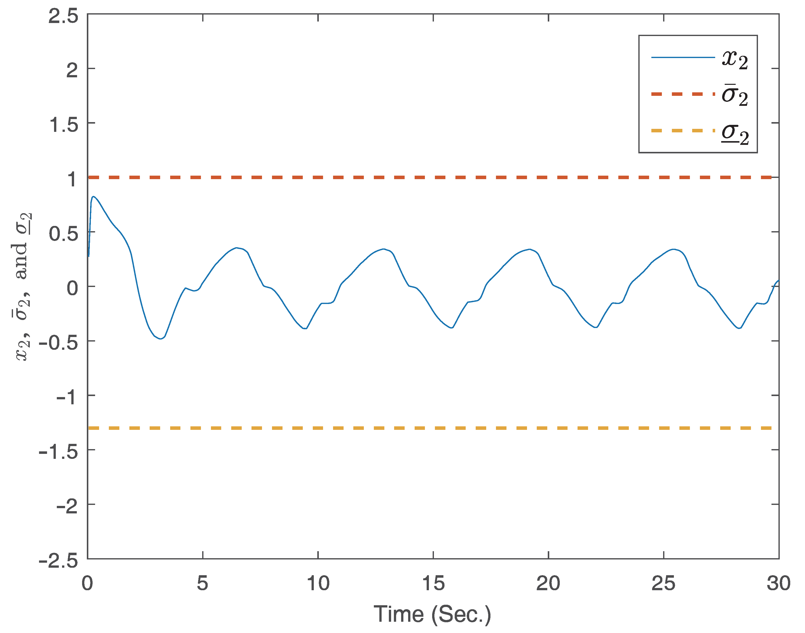
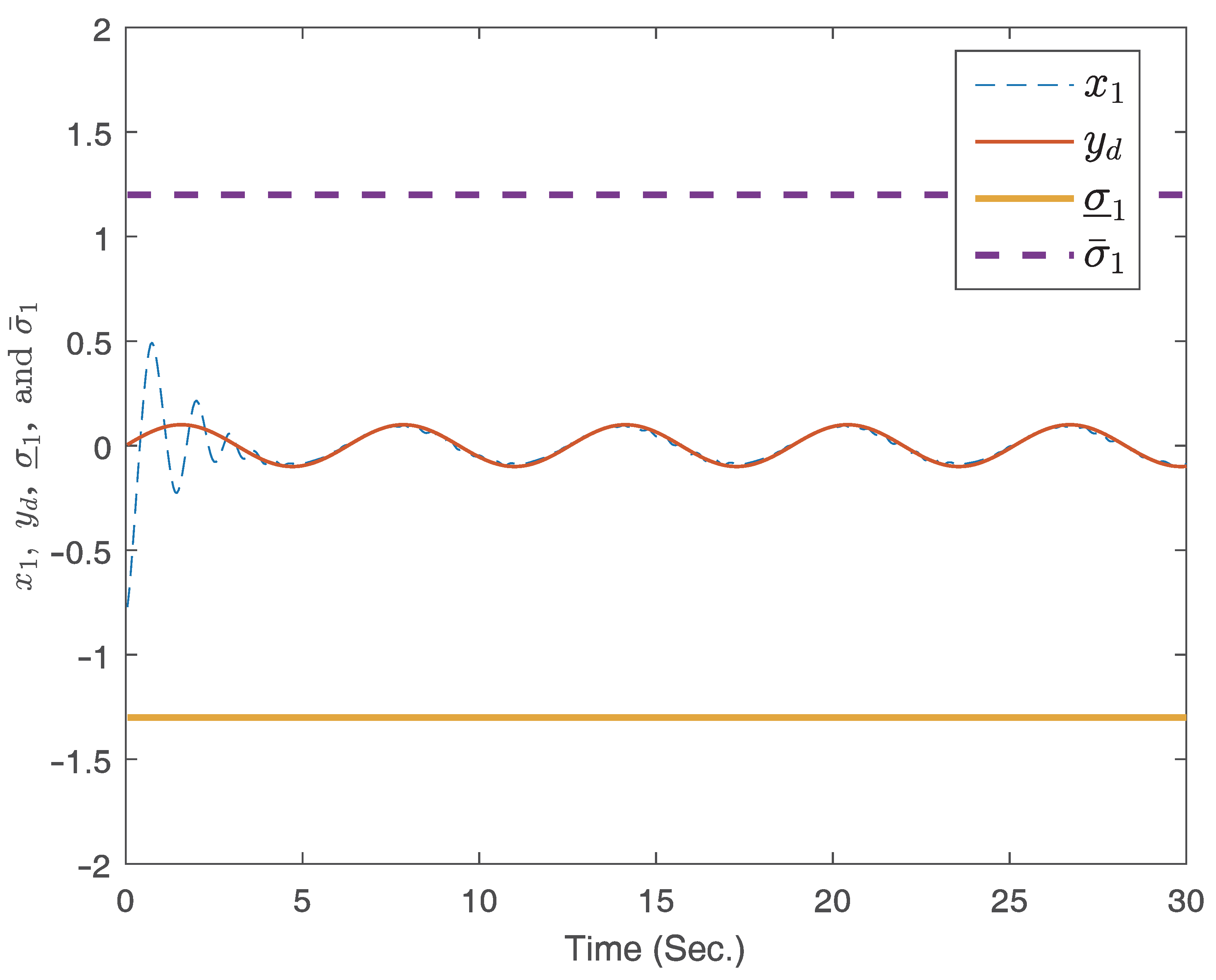
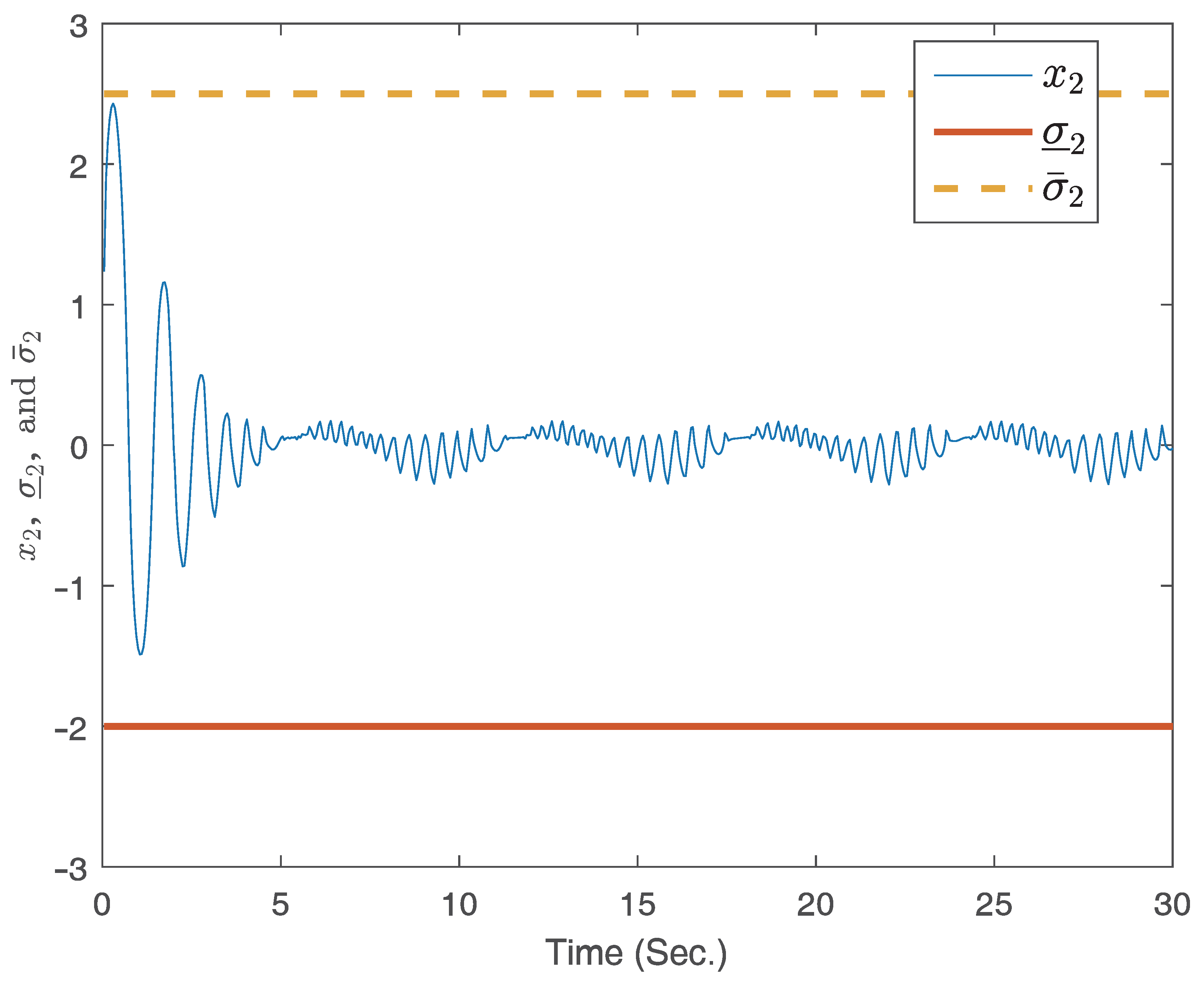
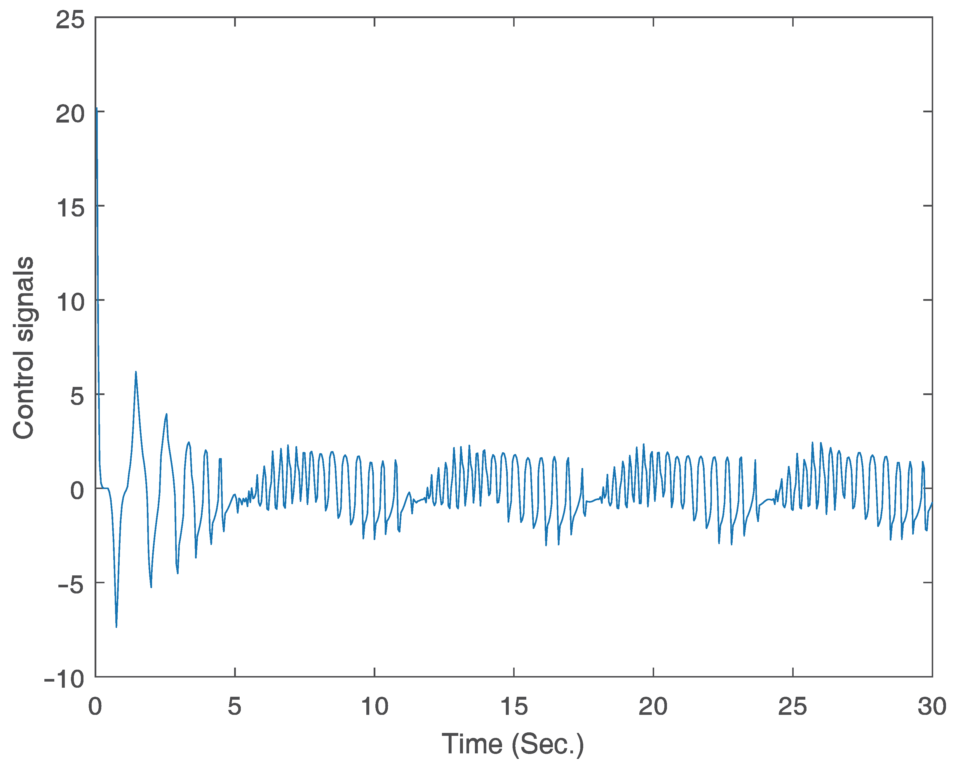
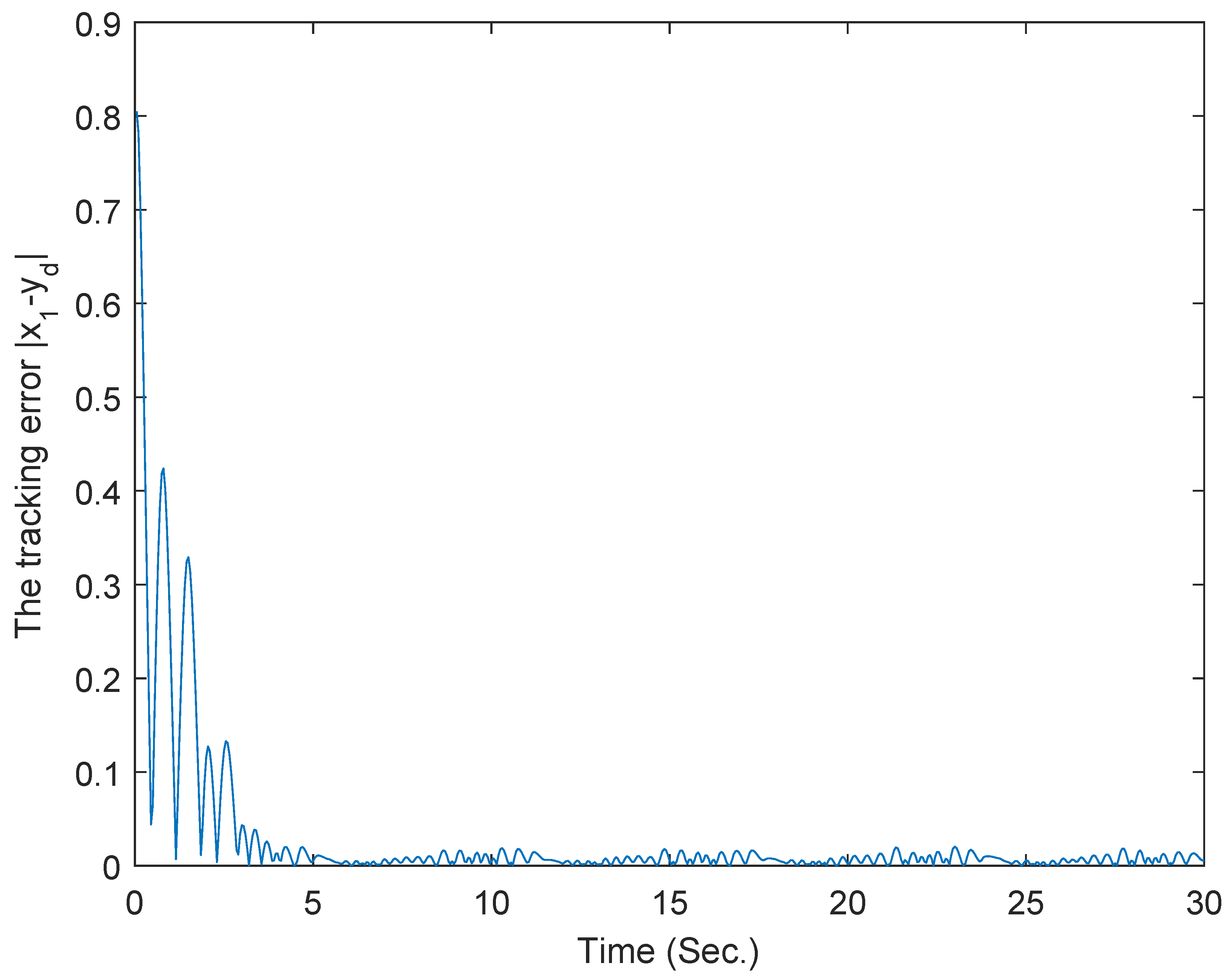
4. Illustrative Examples

In this segment, two instances are presented to demonstrate the efficacy of the developed control strategy.
Example 1.
Examine a damped car system. Its dynamics can be represented by
x ˙ 1 = x 2 + f 1 ( x ) x ˙ 2 = 1 M ( k 0 e x 1 x 1 F d x 2 + u ) y = x 1
where f 1 ( x ) = 0.01 cos ( x 1 ) sin ( x 2 ) is the external disturbances, x 2 denotes the speed of the car, and x 1 denotes the displacement of the car with respect to the rest position. M = 1   kg denotes the mass of the car, and F d = 1.1   Ns/m denotes the damping factor. K = k 0 e x 1 is the stiffness of the spring, k 0 = 0.33   N/m .
Utilizing Theorem 1, the adaptive fuzzy control strategy with finite time (53) for this system is formulated as
u = z 2 θ ¯ ^ 2 2 ϖ 2 ( | z 2 | φ 1 T ( x 2 ) θ ¯ ^ 2 + ϵ 21 * ) z 2 ς ¯ ^ 2 2 ϖ 2 ( | z 2 | ς ¯ ^ 2 + ϵ 22 * ) 1 2 ϖ 2 sgn β ( z 2 ) ϖ 1 z 1 ϖ 2 + ˙ 2 ϖ 2 1 2 z 2 ϖ 2
where the virtual control strategy is
ϑ 1 = z 1 θ ¯ ^ 1 2 ϖ 1 ( | z 1 | φ 1 T ( x 1 ) θ ¯ ^ 1 + ϵ 11 * ) z 1 ς ¯ ^ 1 2 ϖ 1 ( | z 1 | ς ¯ ^ 1 + ϵ 12 * ) + ϖ d y ˙ d ϖ 1 1 2 ϖ 1 sgn β ( z 1 ) 1 2 z 1 ϖ 1
and the adaptation laws are
θ ¯ ^ ˙ i = λ i 1 θ ¯ ^ i + λ i 1 | z i | φ i T ( x i ) , ς ¯ ^ ˙ i = λ i 2 ς ¯ ^ i + λ i 2 | z i | , i = 1 , 2
The parameters are chosen as λ 11 = 0.002 , λ 12 = 0.02 , λ 21 = 0.002 , λ 22 = 0.02 , σ ¯ 1 = 1.2 , σ ̲ 1 = 1.1 , σ ¯ 2 = 1 , σ ̲ 2 = 1.3 , β = 0.3 , y d = 0.3 sin ( t ) , ς ¯ ^ 1 ( 0 ) = 0.01 , x ( 0 ) = [ 0.8 , 0 ] T , θ ¯ ^ 1 ( 0 ) = 0.01 , ς ¯ ^ 2 ( 0 ) = 0.01 , θ ¯ 2 ( 0 ) = 0.01 , ι 1 = 0.5 , ι 2 = 0.5 , ϱ 1 = 0.25 , ϱ 2 = 0.25 , and ϵ = 0.1 .
Results from the simulation are depicted in Figure 2, Figure 3, Figure 4 and Figure 5. Figure 2 and Figure 3 present the response curves for states x 1 , x 2 , and y d , respectively. Notably, states x 1 and x 2 remain within the predefined regions. The curve of the signal for control is displayed in Figure 4.
Example 2.
To underscore the feasibility of the derived control strategy, an example is executed using one-line dynamic behavior of the arm. The equation representing the system’s dynamic balance is
M q ¨ + N q ˙ + R sin ( q ) = F
where F denotes the control input signal, while q represents the arm’s position. Given that R = m g L where L = 1 m is the length of the link, g = 10 N / kg denotes the gravity-induced acceleration, and m = 1 kg corresponds to the mass of the load, M = 1 kg · m 2 is the inertia in mechanical systems. N = 1 N · m · s / rad is the viscous friction coefficient.
Defining x 1 = q and x 2 = q ˙ , then (74) can be reformulated as
x ˙ 1 = x 2 x ˙ 2 = x 2 10 sin ( x 1 ) + u y = x 1
The parameters are designed as λ 21 = 0.002 , λ 22 = 0.02 , σ ¯ 1 = 1.2 , ς ¯ ^ 1 ( 0 ) = 0.01 , ς ¯ ^ 2 ( 0 ) = 0.01 , σ ̲ 1 = 1.3 , σ ¯ 2 = 2.5 , σ ̲ 2 = 2 , y d = 0.1 sin ( t ) , β = 0.3 , x ( 0 ) = [ 0.8 , 0.1 ] T , θ ¯ ^ 2 ( 0 ) = 0.01 , θ ¯ ^ 2 ( 0 ) = 0.01 , ϱ 1 = 0.25 , ϱ 2 = 0.25 , ι 1 = 0.5 , ϵ = 0.1 , and ι 2 = 0.5 . The subsequent emulation results are depicted in Figure 6, Figure 7, Figure 8 and Figure 9, highlighting the practicality of the formulated control approach in managing full-state constraints. The results verify that good tracking performance can be obtained within a finite time and the full-state constraints are not overstepped under the proposed adaptive finite-time fuzzy controller for the two examples. Furthermore, the proposed adaptive finite-time fuzzy controller is available to both the asymmetric and symmetric full-state constraint problems without changing the controller’s structure.

5. Conclusions

This article addresses the adaptive finite-time fuzzy control challenge for nonlinear systems with full-state constraints. Utilizing a nonlinear state-constrained function, we resolved the full-state constraints issues. Drawing upon the dynamic surface control technique and the backstepping method, we devised a fuzzy control strategy with adaptive finite time for uncertain nonlinear systems. The proposed controller can not only ensure that the resulting system is finite-time stable and all the signals in the resulting system are bounded, but can also guarantee that the tracking error is bounded within a finite time and the full-state constraints are maintained. Illustrative examples are shown to illustrate the effectiveness of the proposed control scheme. Future investigation will include considering the event-triggered mechanism in the sensor-to-controller channel for multi-agent systems.

Author Contributions

Y.H.: conceptualization, investigation, methodology, software, writing. X.X.: conceptualization, writing, methodology, investigation. R.L.: conceptualization, writing, methodology, investigation. X.B.: conceptualization, writing, methodology, investigation. H.L.: conceptualization, writing, methodology, investigation. All authors have read and agreed to the published version of the manuscript.

Funding

This work was supported by the Natural Science Foundation of China (52105274), the Natural Science Foundation of Shaanxi Province of China (2022JQ-702), and the Special Scientific Research Program of Shaanxi Provincial Department of Education (21JK0902).

Data Availability Statement

Not applicable.

Conflicts of Interest

The authors declare no conflict of interest.

References

  1. Witkowska, A.; Tomera, M.; Śmierzchalski, R. A backstepping approach to ship course control. Int. J. Appl. Math. Comput. Sci. 2007, 17, 73–85. [Google Scholar] [CrossRef]
  2. Li, G.; Wang, X.; Li, S. Consensus control of higher-order Lipschitz nonlinear multi-agent systems based on backstepping method. IET Control Theory Appl. 2019, 14, 490–498. [Google Scholar] [CrossRef]
  3. Kartal, Y.; Subbarao, K.; Gans, N.R.; Dogan, A.; Lewis, F. Distributed backstepping based control of multiple UAV formation flight subject to time delays. IET Control Theory Appl. 2020, 14, 1628–1638. [Google Scholar] [CrossRef]
  4. Zhuang, H.; Sun, Q.; Chen, Z.; Zeng, X. Robust adaptive sliding mode attitude control for aircraft systems based on back-stepping method. Aerosp. Sci. Technol. 2021, 118, 107069. [Google Scholar] [CrossRef]
  5. Zhang, L.; Ding, H.; Shi, J.; Huang, Y.; Chen, H.; Guo, K.; Li, Q. An adaptive backstepping sliding mode controller to improve vehicle maneuverability and stability via torque vectoring control. IEEE Trans. Veh. Technol. 2020, 69, 2598–2612. [Google Scholar] [CrossRef]
  6. Yu, J.; Shi, P.; Zhao, L. Finite-time command filtered backstepping control for a class of nonlinear systems. Automatica 2018, 92, 173–180. [Google Scholar] [CrossRef]
  7. Capone, A.; Hirche, S. Backstepping for partially unknown nonlinear systems using Gaussian processes. IEEE Control Syst. Lett. 2019, 3, 416–421. [Google Scholar] [CrossRef]
  8. Xiao, Y.; de Ruiter, A.; Ye, D.; Sun, Z. Attitude coordination control for flexible spacecraft formation flying with guaranteed performance bounds. IEEE Trans. Aerosp. Electron. Syst. 2022, 59, 1534–1550. [Google Scholar] [CrossRef]
  9. Jiang, S.; Tian, F.; Sun, S.; Liang, W. Integrated guidance and control of guided projectile with multiple constraints based on fuzzy adaptive and dynamic surface. Def. Technol. 2020, 16, 1130–1141. [Google Scholar] [CrossRef]
  10. Wang, P.; Rui, X.; Yu, H.; Wang, G.; Chen, D. Adaptive control of track tension estimation using radial basis function neural network. Def. Technol. 2021, 17, 1423–1433. [Google Scholar] [CrossRef]
  11. Zhang, H.; Ye, D.; Xiao, Y.; Sun, Z. Adaptive control on SE(3) for spacecraft pose tracking with harmonic disturbance and input saturation. IEEE Trans. Aerosp. Electron. Syst. 2022, 58, 4578–4594. [Google Scholar] [CrossRef]
  12. Wu, Y.; Wang, Z. Fuzzy adaptive practical fixed-time consensus for second-order nonlinear multiagent systems under actuator faults. IEEE Trans. Cybern. 2020, 51, 1150–1162. [Google Scholar] [CrossRef] [PubMed]
  13. Wang, A.; Liu, L.; Qiu, J.; Feng, G. Finite-time adaptive fuzzy control for nonstrict-feedback nonlinear systems via an event-triggered strategy. IEEE Trans. Fuzzy Syst. 2019, 28, 2164–2174. [Google Scholar] [CrossRef]
  14. Li, Y.; Yang, T.; Tong, S. Adaptive neural networks finite-time optimal control for a class of nonlinear systems. IEEE Trans. Neural Netw. Learn. Syst. 2019, 31, 4451–4460. [Google Scholar] [CrossRef]
  15. Ye, D.; Sun, J.; Xiao, Y.; Sun, Z. Energy optimal guidance for proximity approach with obstacle avoidance. Aerosp. Sci. Technol. 2022, 130, 107949. [Google Scholar] [CrossRef]
  16. von Ellenrieder, K.D. Dynamic surface control of trajectory tracking marine vehicles with actuator magnitude and rate limits. Automatica 2019, 105, 433–442. [Google Scholar] [CrossRef]
  17. Li, Y.; Li, K.; Tong, S. Finite-time adaptive fuzzy output feedback dynamic surface control for MIMO nonstrict feedback systems. IEEE Trans. Fuzzy Syst. 2018, 27, 96–110. [Google Scholar] [CrossRef]
  18. Ma, H.; Liang, H.; Zhou, Q.; Ahn, C.K. Adaptive dynamic surface control design for uncertain nonlinear strict-feedback systems with unknown control direction and disturbances. IEEE Trans. Syst. Man Cybern. Syst. 2018, 49, 506–515. [Google Scholar] [CrossRef]
  19. Shi, M.; Ye, D.; Sun, Z.; Zhong, W.; Deng, H. Spacecraft orbital pursuit–evasion games with J2 perturbations and direction-constrained thrust. Acta Astronaut. 2023, 202, 139–150. [Google Scholar] [CrossRef]
  20. Hua, C.; Chen, J.; Li, Y.; Li, L. Adaptive prescribed performance control of half-car active suspension system with unknown dead-zone input. Mech. Syst. Signal Process. 2018, 111, 135–148. [Google Scholar] [CrossRef]
  21. Zerari, N.; Chemachema, M.; Essounbouli, N. Neural network based adaptive tracking control for a class of pure feedback nonlinear systems with input saturation. IEEE/CAA J. Autom. Sin. 2018, 6, 278–290. [Google Scholar] [CrossRef]
  22. Ye, D.; Zou, A.; Sun, Z. Predefined-time predefined-bounded attitude tracking control for rigid spacecraft. IEEE Trans. Aerosp. Electron. Syst. 2021, 58, 464–472. [Google Scholar] [CrossRef]
  23. Chen, G.; Yao, D.; Zhou, Q.; Li, H.; Lu, R. Distributed event-triggered formation control of USVs with prescribed performance. J. Syst. Sci. Complex. 2022, 35, 820–838. [Google Scholar] [CrossRef]
  24. Liu, L.; Liu, Y.; Li, D.; Tong, S.; Wang, Z. Barrier Lyapunov function-based adaptive fuzzy FTC for switched systems and its applications to resistance–inductance–capacitance circuit system. IEEE Trans. Cybern. 2019, 50, 3491–3502. [Google Scholar] [CrossRef] [PubMed]
  25. Fuentes-Aguilar, R.Q.; Chairez, I. Adaptive tracking control of state constraint systems based on differential neural networks: A barrier lyapunov function approach. IEEE Trans. Neural Netw. Learn. Syst. 2020, 31, 5390–5401. [Google Scholar] [CrossRef] [PubMed]
  26. Wu, Z.; Albalawi, F.; Zhang, Z.; Zhang, J.; Durand, H.; Christofides, P.D. Control lyapunov-barrier function-based model predictive control of nonlinear systems. Automatica 2019, 109, 108508. [Google Scholar] [CrossRef]
  27. Li, Y. Barrier Lyapunov function-based adaptive asymptotic tracking of nonlinear systems with unknown virtual control coefficients. Automatica 2020, 121, 109181. [Google Scholar] [CrossRef]
  28. Hwang, Y.; Kang, C.M.; Kim, W. Robust nonlinear control using barrier Lyapunov function under lateral offset error constraint for lateral control of autonomous vehicles. IEEE Trans. Intell. Transp. Syst. 2020, 23, 1565–1571. [Google Scholar] [CrossRef]
  29. Kong, L.; Yu, X.; Zhang, S. Neuro-learning-based adaptive control for state-constrained strict-feedback systems with unknown control direction. ISA Trans. 2021, 112, 12–22. [Google Scholar] [CrossRef]
  30. Liu, R.; Du, H.; Li, Y.; Wei, Y. Finite-time control for nonlinear systems with full-state constraints. In Proceedings of the 2023 2nd Conference on Fully Actuated System Theory and Applications (CFASTA), Qingdao, China, 14–16 July 2023; pp. 987–991. [Google Scholar]
  31. Xia, G.; Liu, C.; Zhao, B.; Chen, X.; Shao, X. Finite time output feedback control for ship dynamic positioning assisted mooring positioning system with disturbances. Int. J. Control Autom. Syst. 2019, 17, 2948–2960. [Google Scholar] [CrossRef]
  32. Li, K.; Li, Y. Adaptive fuzzy finite-time dynamic surface control for high-order nonlinear system with output constraints. Int. J. Control Autom. Syst. 2021, 19, 112–123. [Google Scholar] [CrossRef]
  33. Li, S.; Ahn, C.K.; Xiang, Z. Command-filter-based adaptive fuzzy finite-time control for switched nonlinear systems using state-dependent switching method. IEEE Trans. Fuzzy Syst. 2020, 29, 833–845. [Google Scholar] [CrossRef]
  34. Sun, W.; Wu, Y.; Sun, Z. Command filter-based finite-time adaptive fuzzy control for uncertain nonlinear systems with prescribed performance. IEEE Trans. Fuzzy Syst. 2020, 28, 3161–3170. [Google Scholar] [CrossRef]
  35. Lv, W. Finite time adaptive fault-tolerant control for nonlinear MIMO systems with actuator faults. Int. J. Control Autom. Syst. 2022, 20, 99–108. [Google Scholar] [CrossRef]
  36. Liu, Y.; Zhang, H.; Wang, Y.; Sun, S. Adaptive fuzzy control for nonstrict-feedback systems under asymmetric time-varying full state constraints without feasibility condition. IEEE Trans. Fuzzy Syst. 2021, 29, 976–985. [Google Scholar] [CrossRef]
  37. Hardy, H.; Littlewood, E.; Polya, J. Inequalities; Cambridge University Press: Cambridge, UK, 1995. [Google Scholar]
  38. Deng, H.; Krstic, M. Output-feedback stochastic nonlinear stabilization. IEEE Trans. Autom. Control 1999, 44, 328–333. [Google Scholar] [CrossRef]
  39. Wang, F.; Chen, B.; Liu, X.; Lin, C. Finite-time adaptive fuzzy tracking control design for nonlinear systems. IEEE Trans. Fuzzy Syst. 2017, 26, 1207–1216. [Google Scholar] [CrossRef]
  40. Deng, C.; Yang, G. Distributed adaptive fuzzy control for nonlinear multiagent systems under directed graphs. IEEE Trans. Fuzzy Syst. 2017, 26, 1356–1366. [Google Scholar]
  41. Liang, Y.; Li, Y.; Che, W.; Hou, Z. Adaptive fuzzy asymptotic tracking for nonlinear systems with nonstrict-feedback structure. IEEE Trans. Cybern. 2021, 51, 853–861. [Google Scholar] [CrossRef]
  42. Liu, K.; Wang, R. Antisaturation command filtered backstepping control-based disturbance rejection for a quadarotor UAV. IEEE Trans. Circuits Syst. II Express Briefs 2021, 68, 3577–3581. [Google Scholar] [CrossRef]
  43. Liu, K.; Wang, X.; Wang, R.; Sun, G.; Wang, X. Antisaturation finite-time attitude tracking control based observer for a quadrotor. IEEE Trans. Circuits Syst. II Express Briefs 2020, 68, 2047–2051. [Google Scholar] [CrossRef]
  44. Liu, K.; Yang, P.; Wang, R.; Jiao, L.; Li, T.; Zhang, J. Observer-based adaptive fuzzy finite-time attitude control for quadrotor UAVs. IEEE Trans. Aerosp. Electron. Syst. 2023. [Google Scholar] [CrossRef]
Figure 1. Block diagram of the finite-time control scheme.
Mathematics 11 04313 g001
Figure 2. The curves of the states x 1 and y d .
Mathematics 11 04313 g002
Figure 3. The curve of the state x 2 .
Mathematics 11 04313 g003
Figure 4. The curve of control signal.
Mathematics 11 04313 g004
Figure 5. The curves of tracking error | x 1 y d | .
Mathematics 11 04313 g005
Figure 6. The curves of the states x 1 and y d .
Mathematics 11 04313 g006
Figure 7. The curve of the state x 2 .
Mathematics 11 04313 g007
Figure 8. The curve of control signal.
Mathematics 11 04313 g008
Figure 9. The curve of tracking error | x 1 y d | .
Mathematics 11 04313 g009
Disclaimer/Publisher’s Note: The statements, opinions and data contained in all publications are solely those of the individual author(s) and contributor(s) and not of MDPI and/or the editor(s). MDPI and/or the editor(s) disclaim responsibility for any injury to people or property resulting from any ideas, methods, instructions or products referred to in the content.

