Article

Experimental and Numerical Investigation of Folding Process—Prediction of Folding Force and Springback

1
Department of Mechanical Engineering, College of Engineering, University of Ha’il, Ha’il City 2440, Saudi Arabia
2
Laboratory of Electrochemistry and Environment (LEE), National Engineering School of Sfax, University of Sfax, Sfax 5080, Tunisia
3
Laboratory of Mechanics Modeling and Production, National Engineering School of Sfax, University of Sfax, Sfax 5080, Tunisia
4
Higher School of Sciences and Technology of Hammam Sousse, University of Sousse, Sousse 4002, Tunisia
5
Higher Institute of Technological Studies of Sfax, Sfax 3099, Tunisia
*
Author to whom correspondence should be addressed.
Mathematics 2023, 11(19), 4103; https://doi.org/10.3390/math11194103
Submission received: 5 September 2023 / Revised: 21 September 2023 / Accepted: 27 September 2023 / Published: 28 September 2023
(This article belongs to the Special Issue Advances in Applied Mathematics, Mechanics and Engineering)

Abstract

:
The folding process is characterized by the springback phenomenon. Several experimental folding tests are elaborated and illustrated in this paper. The precision and the quality of the folded sheet workpiece are related to the reduction in the springback phenomena. For that, two tools are designed and used for the folding process. An accurate design of the folding tool plays a significant role in contributing to the folding process and reducing potential defects related to springback. An experimental solution is presented to avoid the forming of defaults and compensate the workpiece springback after its removal from the die. Moreover, an accurate numerical modeling enables an efficient prediction of the springback. This allows us to obtain precise parts through the folding process. For that, a modified Johnson–Cook model is implemented on ABAQUS software in order to predict the folding force and the springback in a U-die folding process. In addition to the isotropic hardening law, a nonlinear kinematic hardening rule is used. To ensure the model’s accuracy and reliability, we conducted validation experiments. The model’s predictions are compared with experimental tests to show its capability to simulate the folding process effectively. The developed mechanical model can adequately predict and analyze springback effects and folding force evolution, helping designers compensate for them and achieve the desired final shape.

1. Introduction

The folding process has a wide range of applications across various industries. It is widely used in sheet metal fabrication to produce complex shapes, which are employed in automotive and aerospace manufacturing. Experimental and numerical studies analyze the quality of the folded piece and the design of the folding tool [1,2,3]. In the first step, several studies were developed to predict the mechanical behavior of sheet metal [4,5,6]. Then, the plasticity and damage law’s parameters were determined. In the second step, in order to gain a better understanding of the folding process, a series of experimental tests were elaborated. Chen et al. [7] examined the springback variation in the U-die folding process of high-strength steel sheets. Experimental tests were used to analyze the influence of material properties, lubrication, and blank holder pressure on the springback variation. Thicker blanks showed less springback variation, while uncoated blanks exhibited lower variations. Other works [8,9] studied the springback variation in the V-die folding process of aluminum, hot-rolled and austenitic stainless steel sheets. They studied the effects of various parameters involved in the V-bending process of the sheets, including the punch holding time, the depth, the sheet thickness, and the material properties, on the springback phenomenon. They found that the punch holding time does not significantly influence the springback, while the material properties and the sheet thickness are the factors most affecting it.
Furthermore, the finite element method (FEM) has undergone significant development and is used for predicting defects in sheet metal forming processes [10,11]. An accurate numerical model enhances overall manufacturing efficiency and improves the quality of folded pieces while minimizing the need for costly experimental tests [12,13]. It has been developed from one-dimensional to three-dimensional problems.
Mechanical and thermomechanical modeling are powerful tools used to analyze and simulate various manufacturing processes [14,15]. Various formulations of mechanical problems were used to model a material’s behavior within its forming process. These models [16,17,18] provide different ways to describe the relationship between stress and strain during plastic deformation. Moreover, other models were formulated in order to predict the behavior of materials under high strain rates and elevated temperatures. The Johnson–Cook model [19] is often used for simulating many manufacturing processes.
In sheet metal forming processes, mechanical models are often sufficient and commonly used to analyze and predict the material’s behavior during forming operations. Mechanical models were developed to simulate the mechanical deformation of sheet metal without considering thermal effects [20,21]. For the folding process, mechanical models may be used to analyze the behavior of materials during bending or folding operations.
Panthi et al. [22] employed a significant deformation algorithm based on the total elastic incremental plastic strain approach to model a sheet metal bending process. In this study, the prediction of the springback was conducted as a numerical experiment in which they analyzed the impact of a load on the springback by varying the thickness and the die geometry.
Nasrollahi et al. [23] discussed the influence of process variables, such as dimension, type, and number of holes, die radius, etc., on the springback. Experiments and numerical analyses were conducted on HSLA360 and St12 materials, showing that the presence of holes in the bending area considerably affects the springback. These findings are leveraged as training data for artificial neural networks (ANNs). In the same context, numerical models used to predict a folding process were developed by using a machine-learning approach. Based on the data obtained from these FEM simulations, the study concluded that there was a high level of agreement between the results of the FE simulator and the machine-learning model [24,25]. Therefore, the machine-learning model can be effectively employed for engineering problems related to springback analysis.
While mechanical models are sufficient for most sheet metal forming applications, coupled thermomechanical models are indispensable in other manufacturing processes, especially those involving heat treatments, thermal deformation, and temperature-dependent material behavior. Various examples of processes where coupled thermomechanical models are commonly used have been illustrated in the literature. In thermoforming and hot forming processes, coupled thermomechanical models are crucial [26,27,28]. They enable the prediction of material behavior, including plastic deformation and springback, accounting for temperature changes during forming. Welding and other joining processes involve localized heating, leading to thermal gradients that affect material properties and generate residual stresses [29,30]. In additive manufacturing processes, where a material is deposited layer-by-layer and then cooled, coupled thermomechanical models are vital. They help in predicting thermal stresses, warping, and reducing defects [31,32].
In machining operations, coupled thermomechanical models are indeed valuable for optimizing cutting parameters to account for thermal damage [14,33,34]. These models take into consideration both the thermal and mechanical aspects of the machining process, allowing researchers to better understand and control how heat affects the workpiece material during cutting. Furthermore, in processes such as laser-assisted milling where high temperatures are involved, addressing the recrystallization effects by incorporating a grain size-dependent parameter into models such as the Johnson–Cook model is crucial as a function of strain, strain rate, and temperature [35].
In this paper, the springback in a U-die folding process is examined. The springback defines the main default of a sheet metal workpiece in a folding process. A mechanical model is developed and implemented on ABAQUS 6.13 software. Experimental tests are elaborated in order to determine the efficiency of this mechanical model in analyzing the folding process. By comparing the results obtained from the experimental tests with those generated by the numerical simulations, we evaluate the robustness and predictive capabilities of our model. In addition to the kinematic hardening rule, the isotropic hardening law, which is the modified Johnson–Cook law, is developed to describe the growth of the yield stress during the folding process. The accuracy of the numerical model predicting the folding force and the springback in the folding process is proved experimentally.

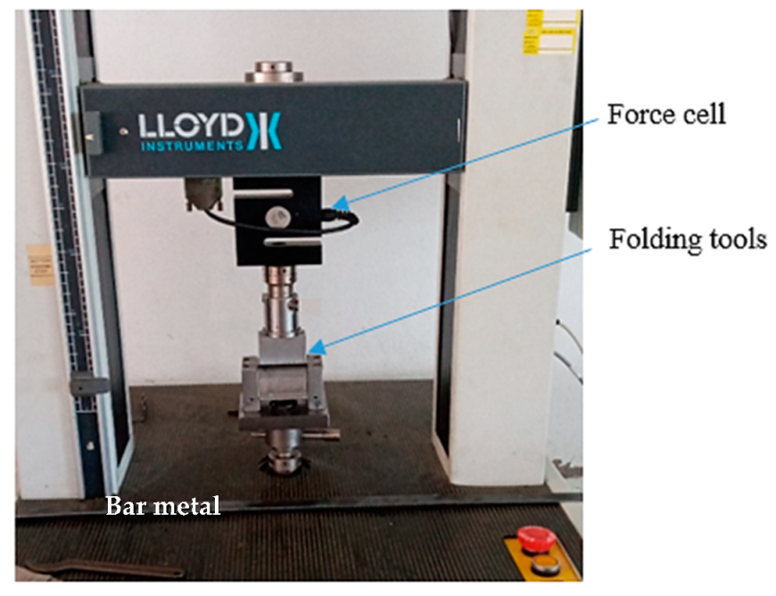
2. Experiments and Methods

A folding process is characterized by the plastic deformation of a flat sheet into a folded configuration. The experimental folding tests are elaborated by a universal tensile machine (Figure 1), which applies the necessary force and bending action to create the folded part of the sheet.
Sheet steel DC01 is investigated in the experimental folding tests. The studied material is a low carbon steel. It has a good ductility level. The chemical composition of DC01 is presented in Table 1.
The experiments are carried out by using two folding tools (Figure 2).
The design and dimensions of the second tool are shown in Figure 3.
The sheet metal was first obtained through a rolling process and then shearing. For the folding process, the sheet metal is positioned on top of the U-die, and a punch applies force to bend the sheet along the groove of the die. We use a load cell with 50 KN as the maximum capacity.
We apply a constant punch speed. For this study, different values of the sheet thickness (e), the punch speed (V), and the orientation angle (θ) are chosen. The values of the process factors are presented in Table 2.
The terms “0°, 45°, and 90°” refer to the rolling direction within the metal sheet (Figure 4).
In the first step, stress–strain curves (Figure 5) are obtained experimentally in order to determine the mechanical properties and behavior of the sheet metal during tensile tests.
Within the three rolling directions of the sheet specimen, the Young’s modulus is not affected, while there was only a minor difference observed in the yield strength and tensile strength values. Then, the DC01 sheet can be characterized as an isotropic material.
This material is suitable for the forming requirements such as folding and drawing. Its mechanical properties are illustrated in Table 3.
In the second step, the springback in the U-die folding process is measured using two tools with different design. The U-die folding refers to a sheet metal forming process where a flat sheet is bent at a 90° angle using a U-shaped die. Figure 6 illustrates the geometry of the folded part.
In order to examine the springback, αexp, in the U-die folding process, experimental tests are conducted. Figure 7 shows examples of the folded parts after the experimental tests. Folding tests are conducted in different orientations, material properties, and folding parameters to understand how the material behaves under different loading conditions.
Table 4 lists the obtained results. The experiments will be repeated twice, and the average of the springback will be calculated to ensure the reproducibility of the findings.
In Figure 8, the experimental variation in the springback is illustrated, which is dependent on sheet thickness, considering various folding conditions and material parameters. The 0° rolling direction within the metal sheet is studied.
From these experimental tests, we deduce the following:
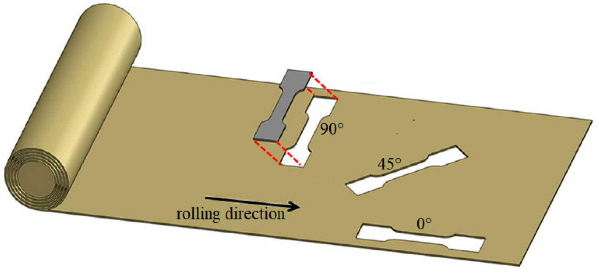
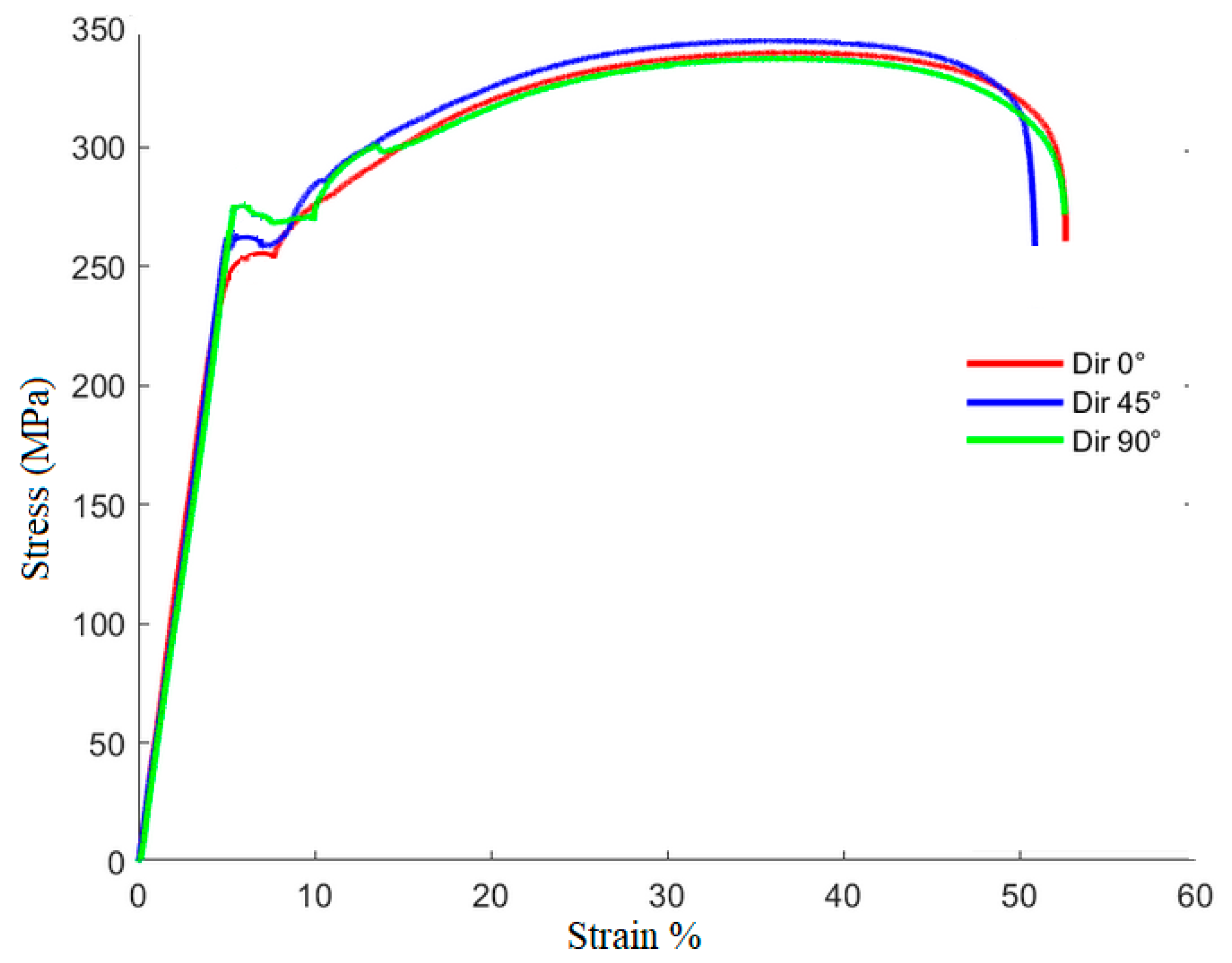
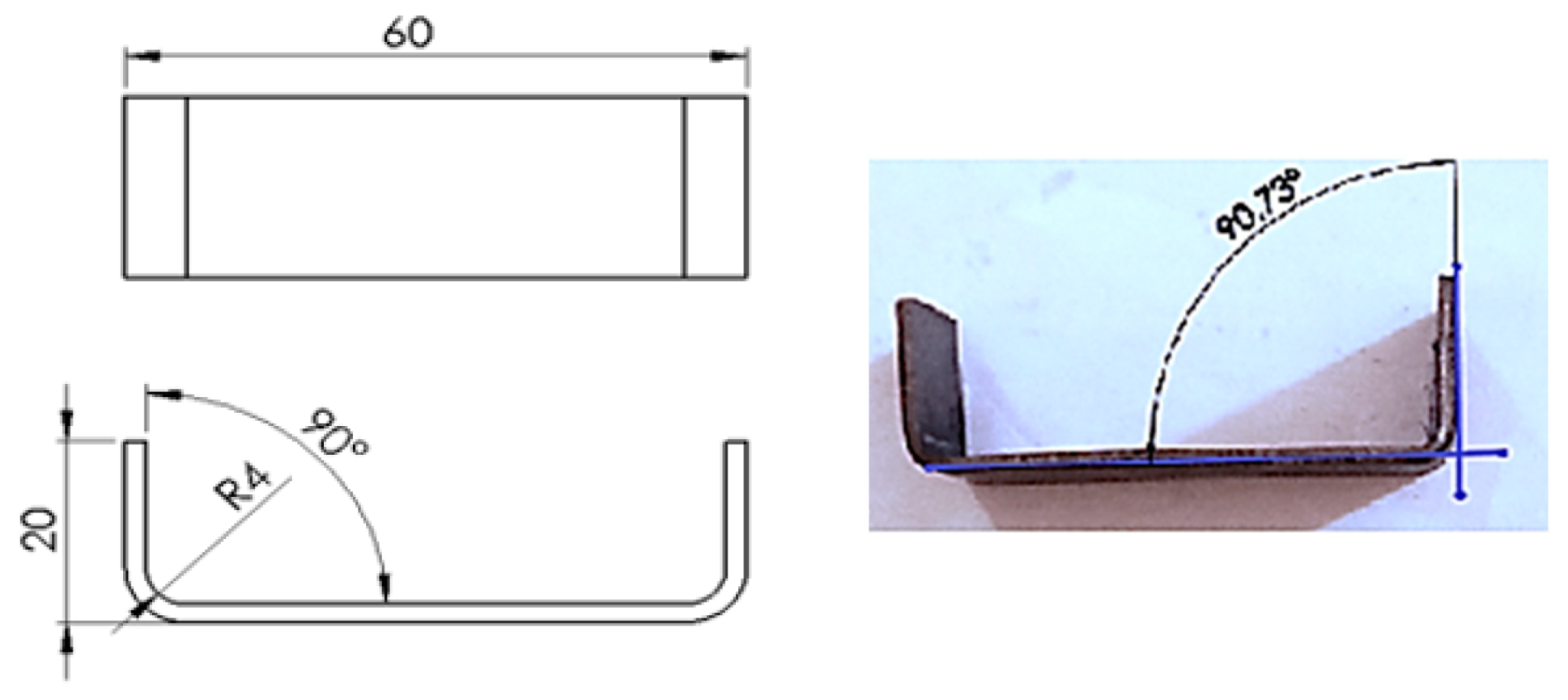
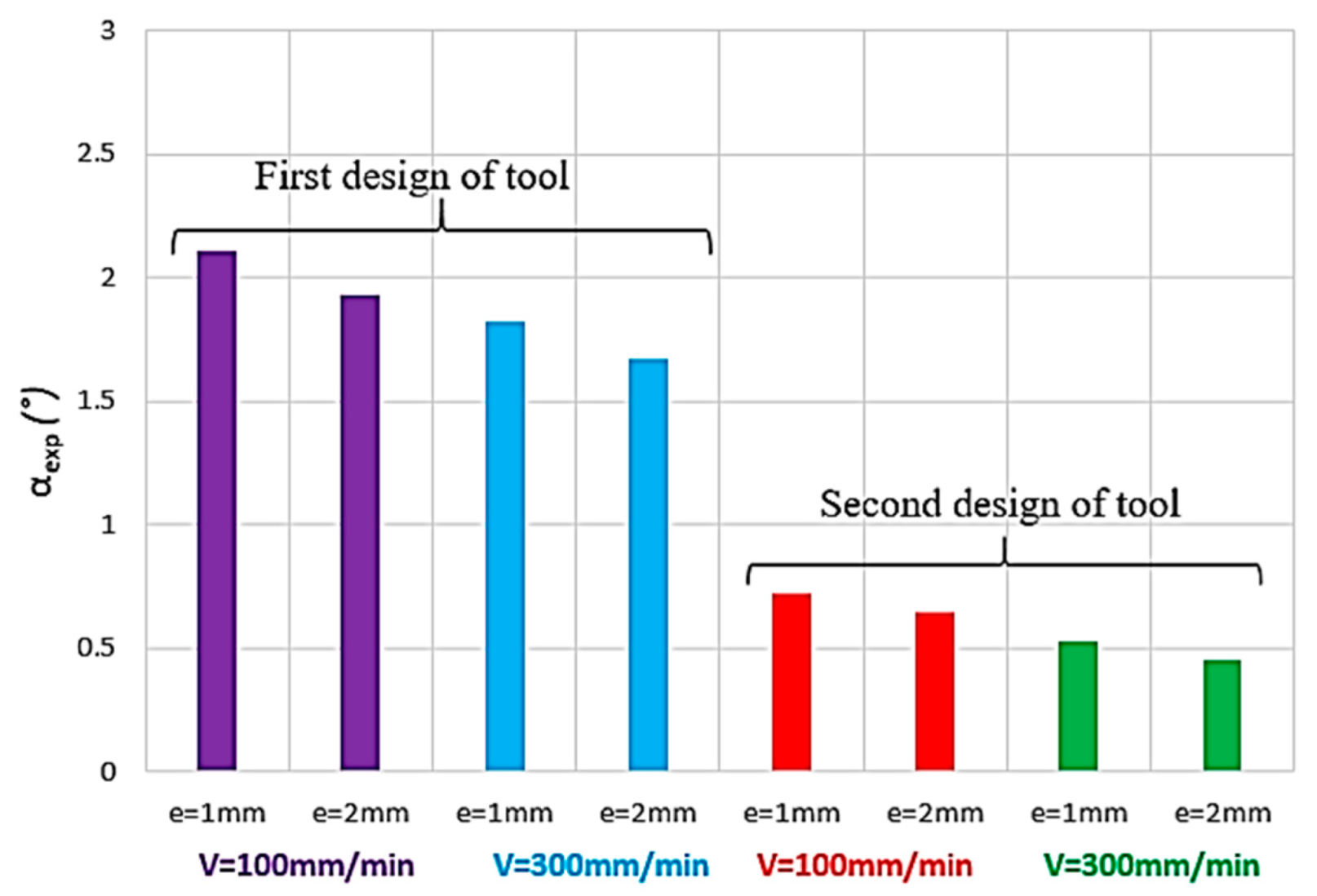
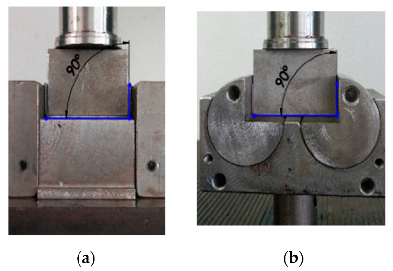
The observed springback variation differs based on the tool design being used. In this context, different levels of springback in different directions are obtained (Table 4). In general, the sheet metal often exhibits anisotropic behavior due to its manufacturing processes, which can introduce preferred grain orientations or crystallographic structures that affect material properties in specific directions. However, in our case, the variation in springback of DC01 with respect to the rolling orientation is low.
The effect of anisotropy on springback is more pronounced for the first tool. This could indicate that the second tool is designed to minimize the effects of anisotropy in the material.
When the sheet metal is subjected to the folding process, the reduced thickness allows for a greater degree of elastic recovery, resulting in a more pronounced springback effect.
Furthermore, the experimental force–displacement curves, with e = 2 mm, V = 100 mm/min and θ = 0°, are illustrated in Figure 9 and Figure 10.
From these curves, we deduce that the first tool requires a higher force to bend the piece. Whereas with the second tool, the effort is reduced. This is mainly due to the different design of the dies and the decreased friction when the second tool is used. In fact, the reduced friction present in the second design further contributes to the lowered effort needed for bending.
In the next sections, a numerical model will be developed and its accuracy will be given based on these experimental tests.

3. Constitutive Formulations of the Hardening Model

A numerical model is developed to predict the springback outcomes in U-die folding tests. To achieve this purpose, constitutive formulations for the hardening model are established. The adapted Johnson–Cook model [19] is used to predict the mechanical behavior of the sheet metal. In the upcoming section, a concise overview of the formulation of this hardening model is provided.
The Johnson–Cook constitutive law is described through a material behavior model, wherein the plastic flow stress, σeq, is decomposed into strain hardening, kinematic hardening, and thermal softening. This model (Equation (1)) utilizes five parameters, which are A, B, n, C, and m, to characterize material behavior under thermomechanical deformation and high-strain-rate conditions.
σ e q = A + B ε p l n 1 + C   l n ε ˙ p l ε ˙ 0 1 T T 0 T m T 0 m
where εpl is the equivalent plastic strain, ε ˙ p l is the strain rate, and ε ˙ 0 is the reference strain rate. T is the absolute temperature, T0 is the reference temperature, and Tm is the melt temperature. A is the initial yield stress. B is the strain-hardening coefficient, indicating how the material’s flow stress increases with plastic deformation. The strain-hardening exponent is denoted n. C is the strain rate coefficient, representing how the material’s flow stress changes with strain rate. The thermal softening parameter, m, indicates the effect of the variation in temperature on the material’s strength.
The Johnson–Cook model relates the flow stress of a material to the strain, strain rate, temperature, and material parameters, which should be determined experimentally.
The deformation of a material is described using a deformation gradient tensor. This tensor is used to define different strain measures, such as the Green–Lagrange strain tensor, which captures the deformation of the material. In addition, the second Piola–Kirchhoff stress tensor is a key component in the Johnson–Cook model because it defines the stress–strain relationship (Equation (1)). In fact, the second Piola–Kirchhoff stress tensor is a measure of the material’s response to the deformation. It is defined in terms of the deformation gradient and the material’s stress response.
The deformation gradient tensor, Fε, is a matrix that relates the initial and the deformed states of the studied material at each point. The multiplicative decomposition of this tensor is given by Equation (2). We define F t h and F p l as the thermo-elastic and the plastic deformation gradient tensors.
F ε = F t h · F p l
The Green–Lagrange strain tensor is used to quantify the strain obtained by a material piece undergoing finite deformation. According to Equation (2), the Green–Lagrange strain tensor, Eε, is separated into thermo-elastic and plastic contributions as follows:
E ε = F p l T · E ~ t h · F p l + E p l  
where I is the identity tensor. The plastic deformation contribution, Epl, is associated with permanent changes in the material’s shape due to dislocation movements. The thermo-elastic strain tensor, E ~ t h , and the plastic strain tensor are illustrated in the following equations.
E ~ t h = 1 2 ( F t h T · F t h I )    
E p l = 1 2 ( F p l T · F p l I )    
Additionally, in order to obtain the different state equations, the specific Helmholtz free energy, Ψ, can be determined and used. In the subsequent analysis, the specific free energy is influenced by a range of state variables. These variables comprise the thermo-elastic strain tensor, the isotropic hardening variable, and a kinematic hardening tensor, A ~ k .
The development of the viscoplastic flow involves formulating the Helmholtz free energy as a function that depends on the reversible components of all the kinematic variables. This energy is decomposed as follows:
Ψ E ~ t h ,   A ~ k , ε p l ,   T   = Ψ t h E ~ t h ,   T   + Ψ γ   T   + Ψ k   A ~ k ,   T   + Ψ i s   ε p l ,   T  
The first term is the thermo-elastic contribution, Ψ t h , given by Equation (7).
Ψ t h = 1 2 ρ E ~ t h : L : E ~ t h 1 ρ E ~ t h : L : α T T 0 + 1 2 ρ α : L L u : α T T 0 2
where L and L u are, respectively, the current and the initial fourth-rank stiffness tensors, ρ is the mass density, and α is the second-rank thermal expansion tensor.
The thermal contribution to the free energy, Ψγ, which is dependent on the absolute temperature, T, can be expressed by Equation (8):
Ψ γ = c 0 γ T 0 T T 0 T   l n T T 0 1 2 γ T T 0 2
The variation in the specific heat capacity with changing temperature is regulated by the material parameters c 0 and γ. This interconnection between different parameters enables an assessment of the material’s thermal response under various conditions, indicating how these parameters affect the material’s thermal characteristics.
In addition, it is postulated that the contribution of the kinematic hardening variable to the free energy follows a quadratic form, thereby reflecting the following:
Ψ k = 1 2 ρ     A ~ k : K : A ~ k
where K is the kinematic hardening modulus tensor.
Furthermore, the contribution of the isotropic hardening (Equation (10)) to the free energy refers to the influence of the accumulated plastic strain on the material’s energy state. Isotropic hardening represents a type of plastic deformation that affects the material’s overall strength without causing a preferential rolling orientation. We denote Bis as the temperature-dependent isotropic hardening modulus.
Ψ i s = 1 ρ   B i s n + 1   ε p l n + 1
In order to account for the reduction in yield stress resulting from an elevation in temperature, it becomes necessary for the hardening modulus to exhibit a dependency on the absolute temperature. The expression below outlines the mechanism of thermal softening:
B i s = B 1 T T 0 T M T 0 m
The specific free energy plays a crucial role in the field of thermodynamics by providing a framework to understand the connection between the state variables of a material and the forces or stresses it experiences. State variables represent the internal characteristics of a material that define its internal state such as strain, temperature, and other properties.
Changes in state variables induce stresses or forces within the material, which drive its behavior during the forming operation. The specific free energy captures the energy associated with these changes and serves as a fundamental tool for formulating the relationship between the state variables and thermodynamic forces of metals.
On the one hand, the second Piola–Kirchoff stress tensor, denoted as S ~ , is a stress measure used to describe the stress state of bending material. It is particularly useful when dealing with non-linear material behavior such as in the folding process. It is related to the deformation gradient tensor. The second Piola–Kirchoff stress tensor is defined by the following equation:
S ~ = ρ Ψ E ~ t h
On the other hand, the scalar stress, R is the dual variable of ε p l . It defines the rise in yield stress due to the strain hardening. The stress, R, is given through the relationship:
R = ρ Ψ ε p l
Based on Equation (10), we obtain
R = B   ε p l n
The yield stress of a material point is defined by Equation (16).
σ y = A i + R
where Ai represents the initial yield stress, which depends on the temperature fields. Ai is the point at which the plastic strain has not yet accumulated. Furthermore, a similar relationship is observed when the parameter Bis is applied.
A i = A 1 T T 0 T M T 0 m
According to the state Equation (14), the yield stress σ y is then given by the following relationship:
σ y = A + B · ε p l n 1 T T 0 T M T 0 m
The evolution of the equivalent plastic strain rate, ε ˙ p l , is known as the viscoplastic flow rule. The following system describes that no plastic flow can occur when the equivalent stress is inferior to the yield stress:
ε ˙ p l = 0         ;   σ e q < σ y   ε ˙ p l 0         ;     σ e q σ y    
The formulation of the viscoplastic flow proceeds as outlined below.
ε ˙ p l =                             0                     ;     σ e q < σ y   ε ˙ 0 ·   e σ e q σ y C   ·   σ y       ;     σ e q σ y    
Based on the yield stress expression, σ y (Equation (17)), and the flow rule definition (system Equation (19)), when σ e q σ y , we obtain the following relationship:
σ y = A + B · ε p l n 1 T T 0 T M T 0 m   ln ε ˙ p l ε ˙ 0 = 1 C σ e q σ y 1      
Based on system Equation (20), the Johnson–Cook model is obtained. This model will be used to simulate the U-die folding process of DC01 steel sheets in the next sections.
In addition, the combination of the Johnson–Cook model with a kinematic hardening model is used in our model in order to predict the springback.
Firstly, the yield surface is given by Equation (21); f σ θ is the equivalent Mises stress, θ is the kinematic shift, and σ 0 is the size of the yield surface.
f σ θ = σ 0
Secondly, a nonlinear kinematic hardening model is used in the developed model. It is given by the following equation, in which the evolution of θ is defined by the Armstrong–Frederick model.
θ ˙ = γ · X s a t · ε ˙ p l γ · θ · ε ˙ e q
where Xsat is the kinematic hardening saturation value and γ is the parameter that determines the kinematic hardening rate. The evolution law’s expression (Equation (22)) specifies that the rate of change in θ due to plastic strain will be in the direction of the current radius vector from the center of the yield surface, denoted as σ θ , while the rate that is dependent on temperature changes points toward the stress space’s origin.

4. Constitutive Model of U-Die Folding Process

Achieving an accurate springback prediction is crucial for automotive manufacturing, aerospace, and sheet metal forming, where precise control over a material’s behavior is essential to producing components with the desired shapes and dimensions. If the plasticity model successfully replicates springback behavior, it can provide valuable insights into optimizing the folding process and minimizing deviations from the intended final shape.

4.1. Folding Model

The developed model shown in the previous section is implemented into the finite element software ABAQUS. The die and punch are considered rigid solids. This means that they do not deform during the process and they have an infinite stiffness. However, the sheet metal is meshed using a 50 × 10 × 5 eight-node linear brick element called C3D8R (Figure 11). It is a reduced integrated element. These elements allow for the simulation of both linear and nonlinear deformations within the sheet metal, making them suitable for capturing the plastic deformation during the folding process.
The punch has one degree of freedom (DOF), which is the translational movement along the z-axis. Furthermore, the die has one DOF, which is the rotation along the y-axis.
As illustrated in Figure 11, the die design allows for minimal friction with the sheet metal.

4.2. Mechanical Model

Mechanical models can adequately predict and analyze springback effects. These models are computationally less intensive than coupled thermomechanical models. This makes them more suitable for rapid simulations and parametric studies.
In the context of a folding process, where a material undergoes plastic deformation followed by elastic recovery (springback), the modified Johnson–Cook model (Equation (23)) can accurately predict springback. The Johnson–Cook modified model is used with the consideration that the strain rate and the temperature effects are not investigated.
σ e q = A + B ε p l n
The logarithm form of Equation (23) can be obtained as shown below:
L n σ e q A = n · L n ε p l + L n B
In order to identify the law parameters of the modified Johnson–Cook model, tensile tests are conducted in order to calibrate the modified Johnson–Cook hardening model. Different specimens are obtained along the three rolling directions. A linear relationship is obtained (Equation (24)) and plotted. A first-order regression model was used to fit the data points, as represented in Figure 12.
From the fitted curve, the Johnson–Cook parameters are predicted as illustrated in Table 5.
By using the modified Johnson–Cook model, we will simulate the folding process and show how the material behaves during both the plastic deformation phase and the subsequent elastic recovery phase. We will show the accuracy of this model in predicting correctly by comparing its force–displacement and springback predictions with the experimental results from the folding process.
In addition, based on Equation (22), the kinematic hardening law’s parameters are given by Table 6.

4.3. Friction Model

The accuracy of the numerical results in the finite element modeling of a folding process is indeed influenced by the choice of friction model. Friction plays a crucial role in determining how forces are transferred between contacting surfaces, affecting the deformation, stress distribution, and overall behavior of the sheet metal being folded. An inaccurate friction model can lead to incorrect predictions of springback behavior. Too much or too little friction can result in deviations from the expected final shape. In this context, the interaction between the die-sheet metal and punch-sheet metal is modeled by the Coulomb friction model (system Equation (25)), allowing for an accurate representation of the forces and deformations at the contact interfaces.
τ f = μ · σ n
where τf is the shear friction stress, μ is the Coulomb friction coefficient, and σn is the contact normal stress.
The stress boundary condition is written as follows:
σ n · n i = T
where the stress vector is T = t x , t y , t z T and ni is the unit normal vector to a boundary element on the stress surface.

5. Accuracy of Numerical Model
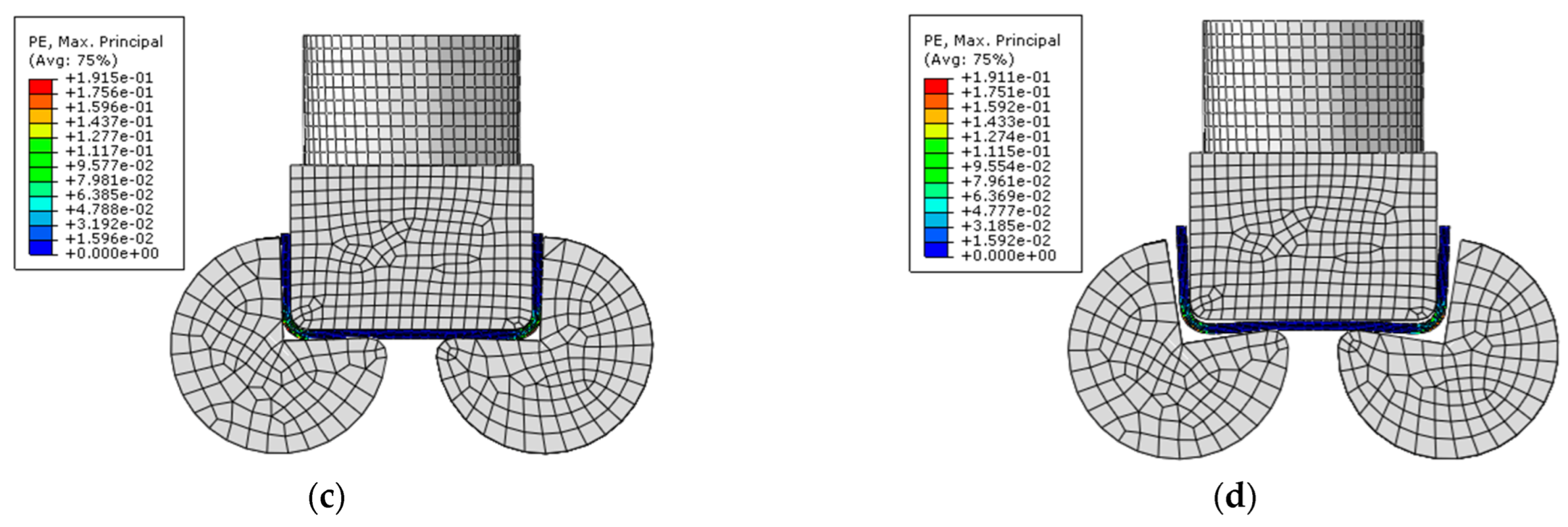
The main goal of this section is to study the accuracy of the developed model in predicting the springback using the second design of the tool.
The first step is to compare the force–displacement curves found experimentally and numerically. The second step is to predict the springback and compare the values found with those obtained experimentally.
Figure 13 illustrates the different steps of the folding test with plastic strain fields.
In addition, springback (Figure 14) is the elastic recovery of the material from its deformed state back toward its original shape. The amount of springback depends on the material’s properties, the degree of plastic deformation, and other factors such as friction.
At the beginning of the folding test, the punch and the sheet material come into contact. The punch applies force to the sheet, initiating the bending process. Initially, elastic deformation occurs, where the sheet slightly bends without undergoing permanent changes. This phase usually occurs before the material reaches its yield point, where plastic deformation starts. As the applied force increases or the bending angle becomes more severe, the sheet material may reach its yield point. At this point, the material undergoes plastic deformation, where it permanently changes shape. Plastic deformation involves the movement of dislocations within the material’s structure, leading to changes in its internal arrangement. After plastic deformation, when the force is released, the sheet metal tends to springback to a certain degree. The relationship between elastic and plastic deformations, as well as the subsequent springback, plays a significant role in determining the final shape and quality of the folded material.
Figure 15 shows a comparison between the evolution of the experimental and numerical force–displacement curves.
A good correlation is found between both force–displacement curves, which proves the mechanical model’s efficacy to compute sheet-folding tests.
Now, a comparison of the computed and the experimental springback is conducted. The calculated error between the computed and experimental values is shown in Table 7.
Based on these results, we deduce the following:
Numerically, as the thickness of the blank sheet metal is reduced, the tendency for springback to occur increases. This phenomenon arises due to the material’s decreased resistance to elastic deformation as it becomes thinner. This result was proved experimentally.
As shown in Table 7, the springback phenomena decreases when the punch speed increases.
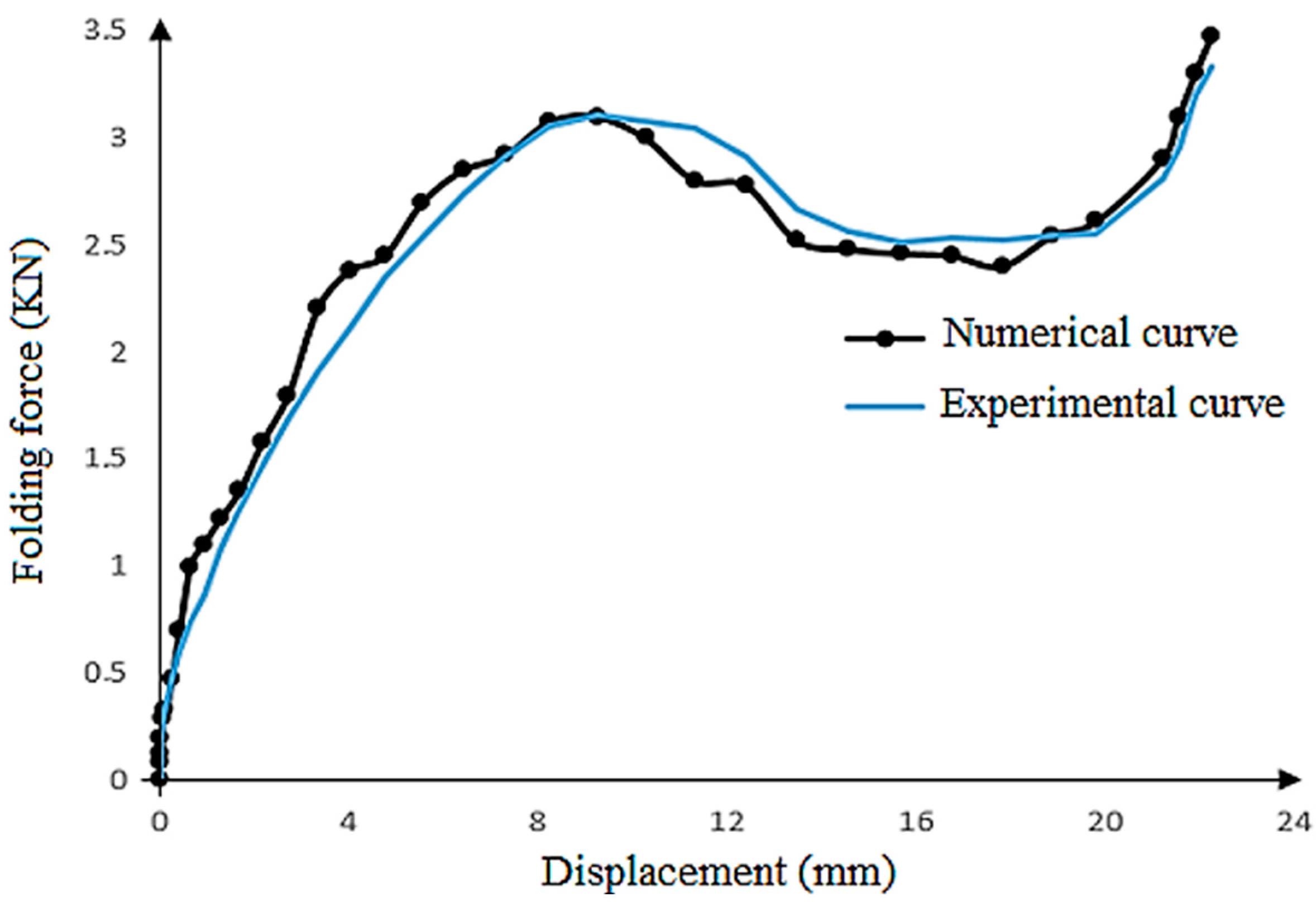
A good agreement between the values of measured the springback and the computed one is revealed.
The computed results of the springback phenomenon are in agreement with the experimental ones for the proposed new tool design.
The modified Johnson–Cook model can accurately predict springback.

6. Conclusions

Achieving precise and high-quality folded sheet workpieces heavily relies on effectively reducing springback phenomena. In fact, springback can lead to dimensional inaccuracies and variations in the final folded part. Our main purpose in this paper is to develop a numerical model in order to predict the springback in a U-die folding process. The accuracy of this model, using a combination of the nonlinear kinematic hardening rule with the modified Johnson–Cook law, is proved experimentally.
In the first step, through our investigation, we found strong evidence linking the occurrence of springback to the design of the tooling used in the folding process.
In the second step, using the second design, the influence of sheet thickness and punch speed on the springback phenomenon was analyzed. A good agreement between the numerical and experimental results was obtained.
The reduction in the thickness of the blank sheet metal leads to an increase in springback.
The springback decreases when the punch speed increases.
Finally, the numerical examples, which are compared with the experimental ones, showed the accuracy of this model to predict the folding force and the springback in the U-die folding process.

Author Contributions

L.B.S.: conceptualization, methodology, writing—original draft preparation. H.H.: software, visualization, data curation, investigation. T.K.: visualization, writing—review and editing, investigation. M.T.: supervision, conceptualization, methodology, writing—review and editing. All authors have read and agreed to the published version of the manuscript.

Funding

This research received no external funding.

Institutional Review Board Statement

Not applicable.

Informed Consent Statement

Not applicable.

Data Availability Statement

Not applicable.

Conflicts of Interest

The authors declare no conflict of interest.

References

  1. Trzepiecinski, T.; Lemu, H.G. Prediction of springback in V-die air bending process by using finite element method. MATEC Web Conf. 2017, 121, 03023. [Google Scholar] [CrossRef]
  2. Leu, D.K. Relationship between mechanical properties and geometric parameters to limitation condition of springback based on springback–radius concept in V-die bending process. Int. J. Adv. Manuf. Technol. 2019, 101, 913–926. [Google Scholar] [CrossRef]
  3. Kut, S.; Pasowicz, G.; Stachowicz, F. On the Springback and Load in Three-Point Air Bending of the AW-2024 Aluminium Alloy Sheet with AW-1050A Aluminium Cladding. Materials 2023, 16, 2945. [Google Scholar] [CrossRef] [PubMed]
  4. Rossi, M.; Lattanzi, A.; Morichelli, L.; Martins, J.M.P.; Thuillier, S.; Andrade-Campos, A.; Coppieters, S. Testing methodologies for the calibration of advanced plasticity models for sheet metals: A review. Strain 2022, 58, e12426. [Google Scholar] [CrossRef]
  5. Hou, Y.; Myung, D.; Park, J.K.; Min, J.; Lee, H.R.; El-Aty, A.A.; Lee, M.G. A Review of Characterization and Modelling Approaches for Sheet Metal Forming of Lightweight Metallic Materials. Materials 2023, 16, 836. [Google Scholar] [CrossRef]
  6. Škrlec, A.; Klemenc, J. Estimating the Strain-Rate-Dependent Parameters of the Johnson-Cook Material Model Using Optimisation Algorithms Combined with a Response Surface. Mathematics 2020, 8, 1105. [Google Scholar] [CrossRef]
  7. Peng, C.; Koç, M.; Wenner, M.L. Experimental investigation of springback variation in forming of high strength steels. J. Manuf. Sci. Eng. 2008, 130, 041006. [Google Scholar]
  8. Meslameni, W.; Ben Salem, C. Modeling of the springback in folding using the experimental design method. J. Appl. Res. Ind. Eng. 2021, 8, 290–308. [Google Scholar]
  9. Ben Salem, C.; Meslameni, W. A numerical investigation on the springback in air v-bending of aluminum 1050 A. Int. J. Res. Ind. Eng. 2022, 11, 119–133. [Google Scholar]
  10. Trzepiecinski, T.; Lemu, H.G. Effect of Computational Parameters on Springback Prediction by Numerical Simulation. Metals 2017, 7, 380. [Google Scholar] [CrossRef]
  11. Ben Said, L.; Allouch, M.; Wali, M.; Dammak, F. Numerical Formulation of Anisotropic Elastoplastic Behavior Coupled with Damage Model in Forming Processes. Mathematics 2023, 11, 204. [Google Scholar] [CrossRef]
  12. Vorkov, V.; Aerens, R.; Vandepitte, D.; Duflou, J.R. Springback prediction of high-strength steels in large radius air bending using finite element modeling approach. Procedia Eng. 2014, 81, 1005–1010. [Google Scholar] [CrossRef]
  13. Lin, J.; Hou, Y.; Min, J.; Tang, H.; Carsley, J.E.; Stoughton, T.B. Effect of constitutive model on springback prediction of MP980 and AA6022-T4. Int. J. Mater. Form. 2020, 13, 1–13. [Google Scholar] [CrossRef]
  14. Ben Said, L.; Wali, M. Accuracy of Variational Formulation to Model the Thermomechanical Problem and to Predict Failure in Metallic Materials. Mathematics 2022, 10, 3555. [Google Scholar] [CrossRef]
  15. Ablat, M.A.; Qattawi, A. Numerical simulation of sheet metal forming: A review. Int. J. Adv. Manuf. Technol. 2017, 89, 1235–1250. [Google Scholar] [CrossRef]
  16. Hollomon, J.H. Tensile deformation. Trans. Metall. Soc. AIME 1945, 162, 268–290. [Google Scholar]
  17. Ludwigson, D.C. Modified stress-strain relation for FCC metals and alloys. Metall.Trans. 1971, 2, 2825–2828. [Google Scholar] [CrossRef]
  18. Swift, H.W. Plastic instability under plane stress. J. Mech. Phys. Solids 1952, 1, 1–18. [Google Scholar] [CrossRef]
  19. Johnson, G.R.; Cook, W.H. A constitutive model and data for metals subjected to large strains, high strain rates and high temperatures. In Proceedings of the 7th International Symposium on Ballistics, The Hague, The Netherlands, 19–21 April 1983. [Google Scholar]
  20. Patel, S.; Lal, R.; Dwivedi, J.P.; Singh, V. Springback Analysis in Sheet Metal Forming Using Modified Ludwik Stress-Strain Relation. ISRN Mech. Eng. 2013, 2013, 640958. [Google Scholar] [CrossRef]
  21. Younas, N.; Chalal, H.; Abed-Meraim, F. Finite Element Simulation of Sheet Metal Forming Processes using Non-Quadratic Anisotropic Plasticity Models and Solid-Shell Finite Elements. Procedia Manuf. 2020, 47, 1416–1423. [Google Scholar] [CrossRef]
  22. Panthi, S.K.; Ramakrishnan, N.; Pathak, K.K.; Chouhan, J.S. An analysis of springback in sheet metal bending using finite element method (FEM). J. Mater. Process. Technol. 2007, 186, 120–124. [Google Scholar] [CrossRef]
  23. Nasrollahi, V.; Arezoo, B. Prediction of springback in sheet metal components with holes on the bending area, using experiments, finite element and neural networks. Mater. Des. 2012, 36, 331–336. [Google Scholar] [CrossRef]
  24. Cruz, D.J.; Barbosa, M.R.; Santos, A.D.; Miranda, S.S.; Amaral, R.L. Application of Machine Learning to Bending Processes and Material Identification. Metals 2021, 11, 1418. [Google Scholar] [CrossRef]
  25. Trzepieci´nski, T.; Lemu, H.G. Improving prediction of springback in sheet metal forming using multilayer perceptron-based genetic algorithm. Materials 2020, 13, 3129. [Google Scholar] [CrossRef] [PubMed]
  26. Ghobadnam, M.; Mosaddegh, P.; Rezaei Rejani, M. Numerical and experimental analysis of HIPS sheets in thermoforming process. Int. J. Adv. Manuf. Technol. 2015, 76, 1079–1089. [Google Scholar] [CrossRef]
  27. Abedrabbo, N.; Pourboghrat, F.; Carsley, J. Forming of AA5182-O and AA5754-O at elevated temperatures using coupled thermo-mechanical finite element models. Int. J. Plast. 2007, 23, 841–875. [Google Scholar] [CrossRef]
  28. Poloczek, Ł.; Rauch, Ł.; Wilkus, M.; Bachniak, D.; Zalecki, W.; Pidvysotsk’yy, V.; Kuziak, R.; Pietrzyk, M. Physical and Numerical Simulations of Closed Die Hot Forging and Heat Treatment of Forged Parts. Materials 2021, 14, 15. [Google Scholar] [CrossRef] [PubMed]
  29. Schmidt, H.B.; Hattel, J.H. A local model for the thermomechanical conditions in friction stir welding. Model. Simul. Mater. Sci. Eng. 2005, 13, 77. [Google Scholar] [CrossRef]
  30. Sonne, M.R.; Tutum, C.C.; Hattel, J.H. The effect of hardening laws and thermal softening on modeling residual stresses in FSW of aluminum alloy 2024-T3. J. Mater. Process. Technol. 2013, 213, 477–486. [Google Scholar] [CrossRef]
  31. Denlinger, E.R.; Irwin, J.; Michaleris, P. Thermomechanical Modeling of Additive Manufacturing Large Parts. ASME J. Manuf. Sci. Eng. 2014, 136, 061007. [Google Scholar] [CrossRef]
  32. Shen, N.; Chou, K. Simulations of Thermo-Mechanical Characteristics in Electron Beam Additive Manufacturing. In Proceedings of the ASME 2012 International Mechanical Engineering Congress and Exposition: Design, Materials and Manufacturing, Parts A, B, and C, Houston, TX, USA, 9–15 November 2012; ASME: New York, NY, USA, 2013; Volume 3, pp. 67–74. [Google Scholar] [CrossRef]
  33. Hentati, H.; Naceur, I.B.; Bouzid, W.; Maalej, A. Numerical analysis of damage thermo-mechanical models. Adv. Appl. Math. Mech. 2015, 7, 625–643. [Google Scholar] [CrossRef]
  34. Ben Said, L.; Chabchoub, A.K.; Wali, M. Mathematical Model Describing the Hardening and Failure Behaviour of Aluminium Alloys: Application in Metal Shear Cutting Process. Mathematics 2023, 11, 1980. [Google Scholar] [CrossRef]
  35. Pan, Z.; Feng, Y.; Lu, Y.T.; Lin, Y.F.; Hung, T.P.; Hsu, F.C.; Liang, S.Y. Force modeling of Inconel 718 laser-assisted end milling under recrystallization effects. Int. J. Adv. Manuf. Technol. 2017, 92, 2965–2974. [Google Scholar] [CrossRef]
  36. Tuninetti, V.; Yuan, S.; Gilles, G.; Guzmán, C.F.; Habraken, A.M.; Duchêne, L. Modeling the ductile fracture and the plastic anisotropy of DC01 steel at room temperature and low strain rates. J. Phys. Conf. Ser. 2016, 734, 032075. [Google Scholar] [CrossRef]
Figure 1. Experimental folding tools.
Mathematics 11 04103 g001
Figure 2. (a) First design of folding tool; (b) second design of folding tool.
Mathematics 11 04103 g002
Figure 3. Design and dimensions of second tool.
Mathematics 11 04103 g003
Figure 4. Orientation angles.
Mathematics 11 04103 g004
Figure 5. Stress–strain curves of tensile tests of DC01.
Mathematics 11 04103 g005
Figure 6. Folded part geometry and springback after experimental folding test.
Mathematics 11 04103 g006
Figure 7. Folded parts after experimental folding tests.
Mathematics 11 04103 g007
Figure 8. Springback variation for the cases of rolling orientation 0°.
Mathematics 11 04103 g008
Figure 9. Experimental force–displacement curve with first tool. (e = 2 mm, V = 100 mm/min and θ = 0°).
Mathematics 11 04103 g009
Figure 10. Experimental force–displacement curve with second tool (e = 2 mm, V = 100 mm/min and θ = 0°).
Mathematics 11 04103 g010
Figure 11. Numerical model of folding process.
Mathematics 11 04103 g011
Figure 12. Logarithm curve of Johnson–Cook hardening model.
Mathematics 11 04103 g012
Figure 13. Different steps of computed folding test with plastic strain fields. (a) 3D representation of U-die folding process (b) during the U-die folding process; (c) at the end of the U-die folding process; (d) after the release phase of the folding operation.
Mathematics 11 04103 g013aMathematics 11 04103 g013b
Figure 14. Computed springback.
Mathematics 11 04103 g014
Figure 15. Numerical and experimental force–displacement curves. (e = 2 mm, V = 100 mm/min, and θ = 0°).
Mathematics 11 04103 g015
Table 1. Chemical composition of the DC01 sheet steel (EN 10130).
CMnPS
≤0.12≤0.6≤0.045≤0.045
Table 2. Input factors in folding tests.
Sheet Thickness
e (mm)
Punch Speed
V (mm/min)
Orientation Angles
θ (°)
Value1210030004590
Table 3. Elastic properties of DC01 sheet metal.
Young’s Modulus (GPa)Poisson’s Ratio
2100.3
Table 4. Experimental springback.
Test Numbere (mm)V (mm/min)θ (°)αexp (°)
for First Design of Tool
Mathematics 11 04103 i001
αexp (°)
for Second Design of Tool
Mathematics 11 04103 i002
1110002.10.73
2210001.930.65
3130001.820.53
4230001.670.45
51100452.170.74
61100902.250.76
Table 5. Prediction of Johnson–Cook parameters for DC01.
A (MPa)Bn
2506410.9
Table 6. Kinematic hardening law parameters for DC01 [36].
γXsat (MPa)
113.6381.96
Table 7. Comparison between experimental and numerical results.
Test Numberαexp (°)
Mathematics 11 04103 i003
αnum (°)
Mathematics 11 04103 i004
Error (%)
10.730.721.39%
20.650.673.08%
30.530.553.77%
40.450.474.44%
50.740.731.35%
60.760.733.95%
Disclaimer/Publisher’s Note: The statements, opinions and data contained in all publications are solely those of the individual author(s) and contributor(s) and not of MDPI and/or the editor(s). MDPI and/or the editor(s) disclaim responsibility for any injury to people or property resulting from any ideas, methods, instructions or products referred to in the content.

