1. Introduction
Nowadays energy and the environment are the two major concerns to reduce pollution and energy consumption, especially in the automobile industry. Compared to the IC engine vehicle, the electric vehicle (EV) has many advantages. The electric drive system of EVs is divided into three parts: power supply, control system and motor drive [
1,
2]. So far manufacturers have preferred Permanent Magnet Motors (PMMs), Induction Motors and DC Motors in drive system. Though DC motors are easy to control, maintenance problems due to brushes and commutator are the reason for their limited use. The control system of AC motor drive contains a power converter and control strategy. The power converter is mainly used to convert the dc voltage to three phase voltage using a 3Φ inverter, and the control strategies to control the speed or torque are Variable Voltage Variable Frequency (VVVf) Control, Direct Torque Control (DTC), Direct and Indirect Field oriented control and power-based control, etc. For the speed control of motor drives, correct information on speed is necessary to achieve faster dynamic performance. The speed sensor is mounted conventionally on the motor shaft to measure the speed, but the sensor is unreliable because of noise. Further space is required to mount the sensor, and circuitry and wiring of the sensor will make the sensor more unreliable. Therefore, many researchers are attracted towards sensorless speed control techniques.
Sensorless speed control techniques are largely divided into three groups: state observer methods, indirect measurement methods and saliency-based methods. Generally, the state observer uses back emf or flux linkage to estimate the speed of the motor. Since the back emf is directly proportional to the rotor speed, at low-speeds, the back emf-based method will perform poorly. However, the saliency-based method solves this problem, because in a salient rotor machine the phase inductance has the information of the rotor position. Indirect measurement methods estimate the rotor speed by measuring special harmonic waveforms. The current-based MRAS model is also popular for estimating the low speed as the reference model contains Id Iq, which is independent of voltage, so the adaptive model’s Id Iq will get close to the reference model’s Id Iq with the help of adaptation mechanism, and during low voltage the reference model’s Id Iq will also not change. Hence, with the adaptive model, the estimation of Id Iq will be much more accurate [
3,
4,
5,
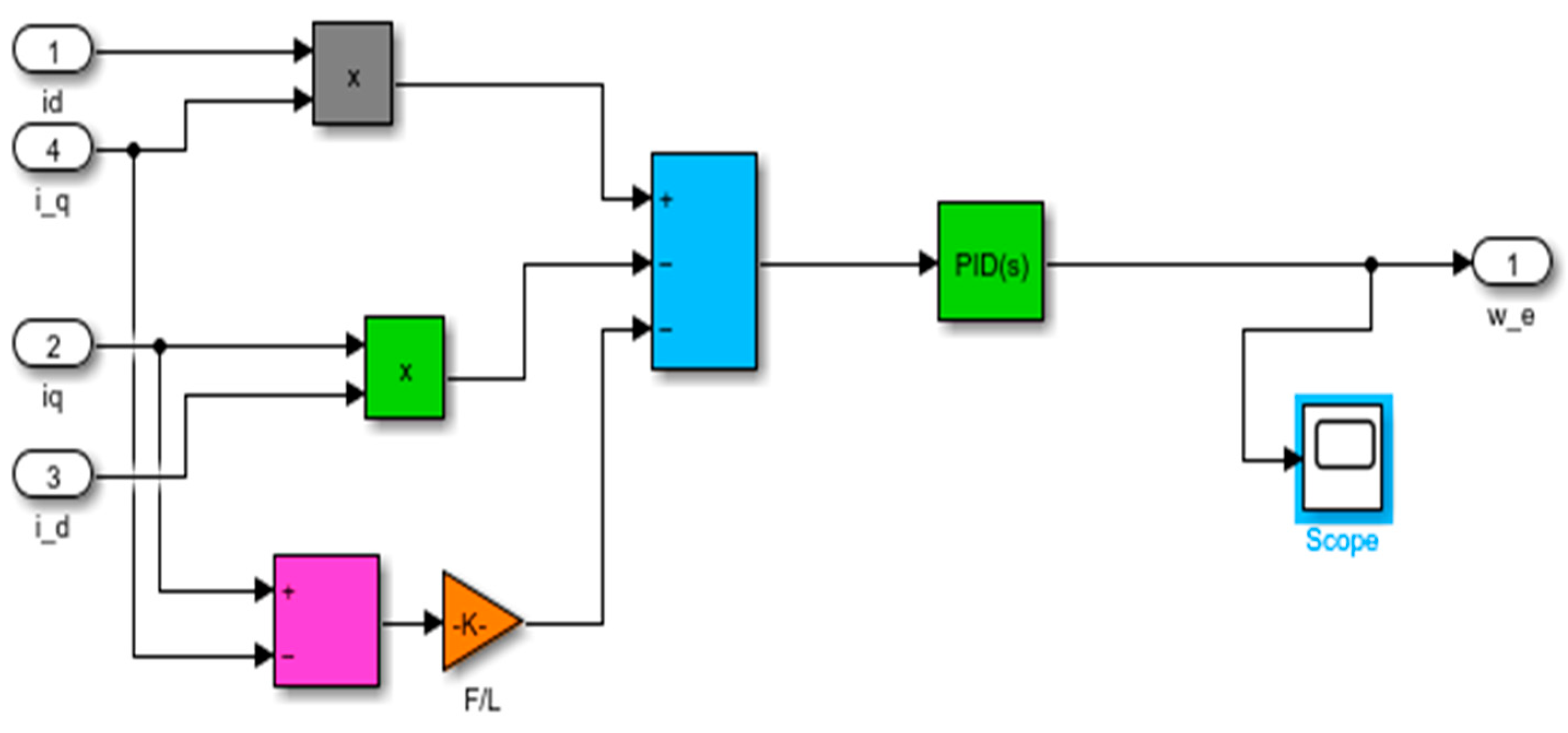
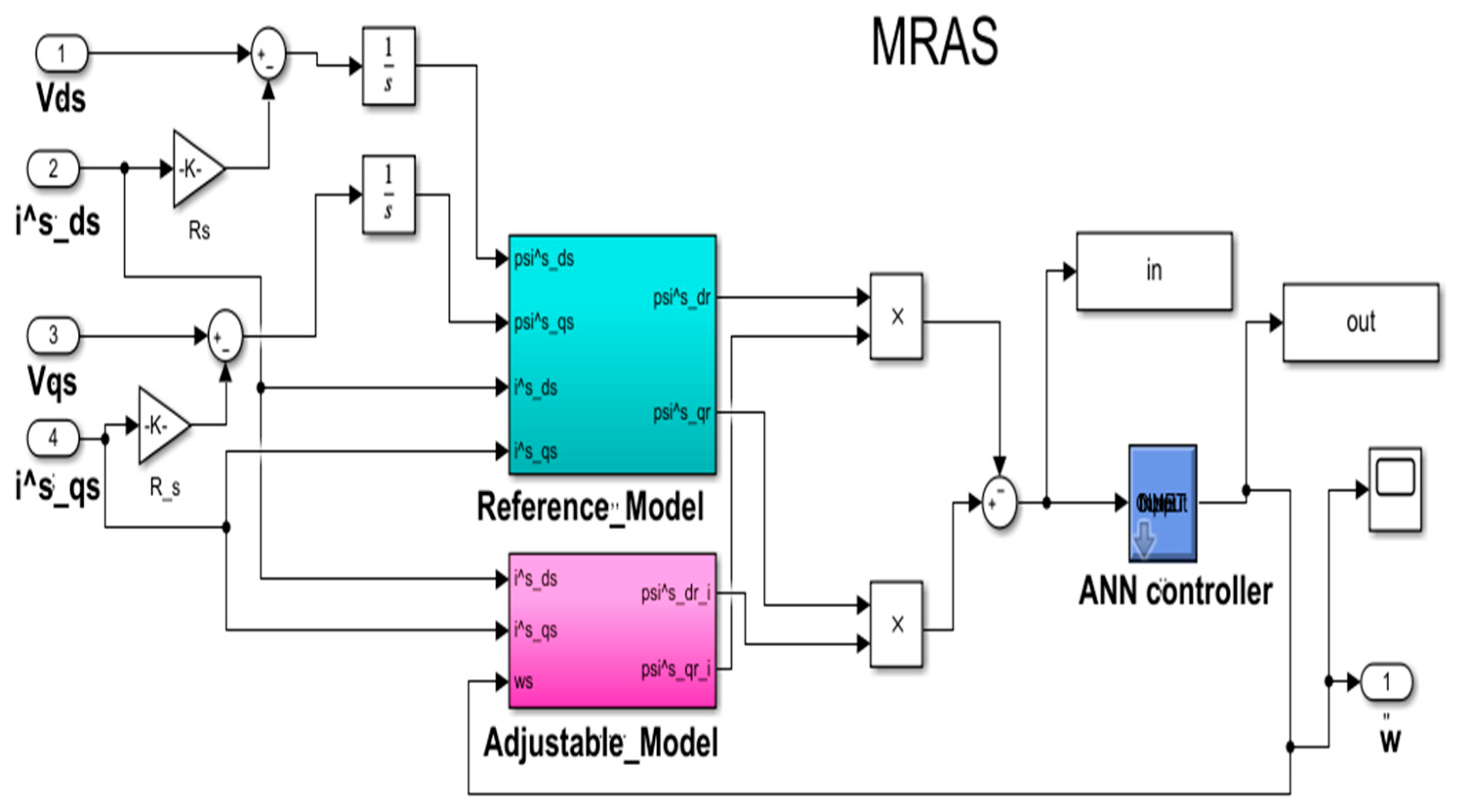
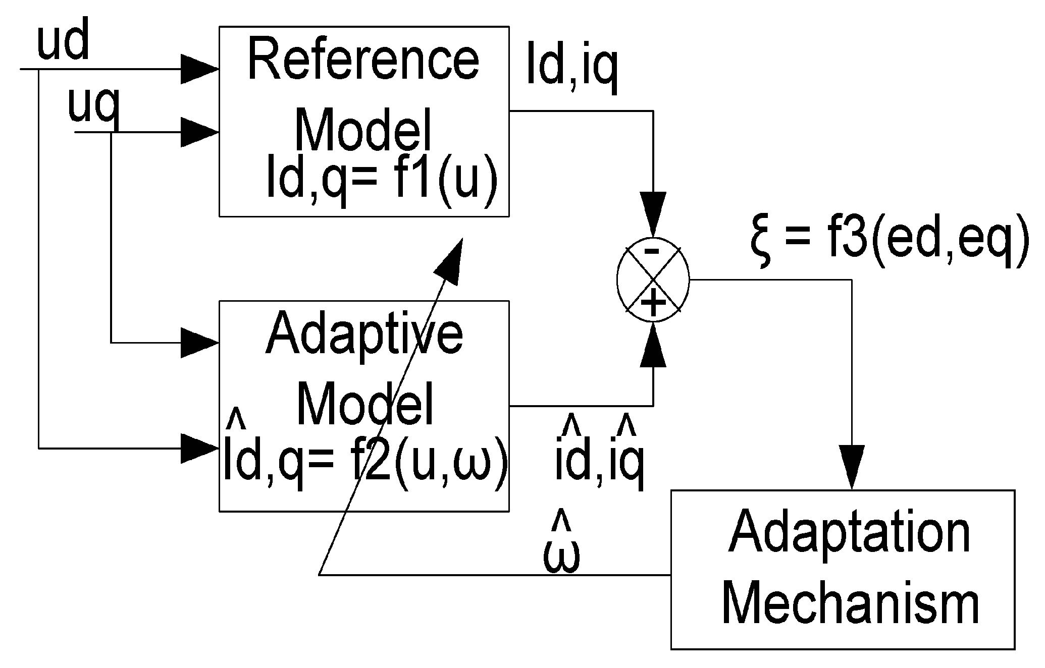
6]. Further, in the current-based model reference adaptive system (MRAS), the speed estimation algorithm used is independent of stator resistance, no error due to the integrator being the back emf estimation is required for this algorithm, and it is less computational and provide stable operation for the drive system. The reference model of a current-based MRAS is shown in
Figure 1. It depends on Id Iq current, and these currents are independent of voltage supply, as Id is set as equal to zero for the PMSM drive, and Iq depends on torque value. Therefore, even at low speed and zero speed, the estimation of speed will be correct.
In EVs, the energy efficiency or WH/km at all speeds will be different. For example, if a vehicle accelerates, it consumes tremendous amounts of power depending upon the acceleration, the time of idling (Stopped during red light) and the time of deceleration, where it gives some power back but only fraction of energy. The concept of similar drive is based on various regulators, which defines some standard drives, and to obtain the performance of a vehicle as per the concept of drive cycle, the power required, maximum torque required, energy required and the energy efficiency WH/km must be known. Hence in this paper, a modified Indian drive cycle is developed and used for the analysis [
7,
8,
9,
10,
11].
There are several AI-based methods that have been investigated for modifying PI speed controllers in PMSM systems. These techniques aim to improve the performance of the PI controller by dynamically altering its settings in response to system inputs, such as Particle Swarm Optimization (PSO), Differential Evolution (DE), Genetic Algorithms (GAs), etc. Convergence might be delayed, though, and it is also important to choose the right parameters and determine the target function for a good implementation. Artificial Neural Networks (ANNs) provide several advantages over optimization methods like PSO, GA, and other optimization techniques for altering PI speed controllers in PMSMs. Because they can learn intricate nonlinear connections and change parameters based on real-time input, ANNs excel in flexibility and adaptability. Their generalization capacity, as opposed to PSO and GA, enables good performance in untrained circumstances. ANNs are suitable for uncertain and nonlinear control settings since they do not rely as heavily on precise mathematical models. With less need for re-optimization, they offer increased resilience by tolerating parameter fluctuations and disturbances. Additionally, ANNs allow for faster computation rates, enabling real-time control applications. Overall, these advantages highlight ANNs as a possible method for achieving the best control performance in PMSMs [
12,
13,
14,
15].
Furthermore, to enhance the performance of drive intelligent controllers, artificial neural network-based controllers need to be used in place of PI controllers as PI controller Kp, Ki value depends on the parameters of a machine, which will vary due to temperature changes. The Kp, Ki value of PI controllers will not change by itself, so to get rid of this problem, an Artificial Neural Network (ANN)-based controller is needed. Once the ANN-based controller is trained, it changes the Kp, Ki value itself. Hence, the performance of EVs can be improved through the replacement of the PI controller.
This paper presents an artificial neural network (ANN)-deployed sensorless speed control of permanent magnet synchronous motor (PMSM) drive for EVs.
Section 2 discusses the drive system used in electric vehicles. In
Section 3, the estimation of speed using the current-based MRAS model is discussed and compared with the proposed ANN-based controller, which improves the performance of EV motor drives significantly. The MATLAB simulation results are presented to validate the proposed algorithm in comparison with widely used, current-based MRAS speed estimation.
Section 4 presents the experimental analysis to validate the proposed algorithm, and
Section 5 concludes the research.
2. Drive System of Electric Vehicle
Usually, the electric drive system of an EV is divided into three parts: power supply, control system and motor drive.
- A.
Permanent Magnet Synchronous Motor
The development of permanent magnet over the years from Alnico 5 to NdFeB has increased the value of energy density of NdFeB up to seven times as compared to Alnico 5, meaning that if we use NdFeB magnet in place of Alnico 5 to generate the same power, the machine size will reduce sevenfold. So due to the high energy density of the permanent magnet, the size of motors can be reduced, but the cost of the permanent magnet is high, which increases the cost of motors. Compared with Induction motors (IM), PMMs have an edge in terms of operating efficiency, but the IM are cheaper, and field weakening is possible to increase the range of operating speed. PMMs are not recyclable, whereas IM are easy to recycle. The control system of motor drive contains power converter and control strategy. Power converter is mainly used to convert the dc voltage to three phase voltage using a three-phase inverter, and the control of machine by using scalar control or by vector control techniques [
9,
10].
- B.
Vector Control of Motor Drives
In the year 1972, F. Blaschke introduced field-oriented control or vector control to control the ac induction motor, just like the separately excited dc motor. In the separately excited dc motor, the field flux is perpendicular to the armature flux, hence, there is no interaction between both fluxes, so the flux and speed or torque of the machine can be controlled separately by adjusting the field current for flux control and armature current for the torque. In the ac machine, the rotor flux and stator flux are not displaced by 90 degrees, but can be obtained with the help of vector control. In synchronously rotating frames (d-q), where d axis is aligned along the rotor flux, the torque and flux will be decoupled, and hence, the flux control and torque control are obtained separately [
3,
4,
5,
6].
- C.
Sensorless Speed Estimation
To achieve quick dynamic performance, reliable speed information is required for motor drive speed regulation. The rotor speed is normally measured using a speed sensor installed on the motor shaft; however, noise makes the sensor unreliable. Additional wire and electrical circuits increase the cost of the driving system, as well as the amount of space required. As a result, numerous academics are interested in working in the subject of speed sensorless motor driving. The three types of sensorless approaches include state observer, indirect measurement method and saliency based. In current-based model reference adaptive system (MRAS), the speed estimation algorithm used is independent of stator resistance, no error due to integrator as back emf estimation is not required for this algorithm, it is less computational and provides a stable operation of the drive system. The model of current-based MRAS is shown in
Figure 2.
PMSM is the reference model so id iq current can be taken directly from the PMSM drive. The adaptive model of PMSM drive is described via the equation where
,
currents change according to
. The intermediate signal
is formed as:
The intermediate signal
formed is given via the following equation:
PI controller is used in the adaptation mechanism to process the error and to tune the adjustable model to achieve the estimated rotor speed.
The accuracy and the drift problem at low speed is inherent due to the open integration in the reference model, and it accumulates further if the gains are not retuned again.
- D.
EV Driving Cycle
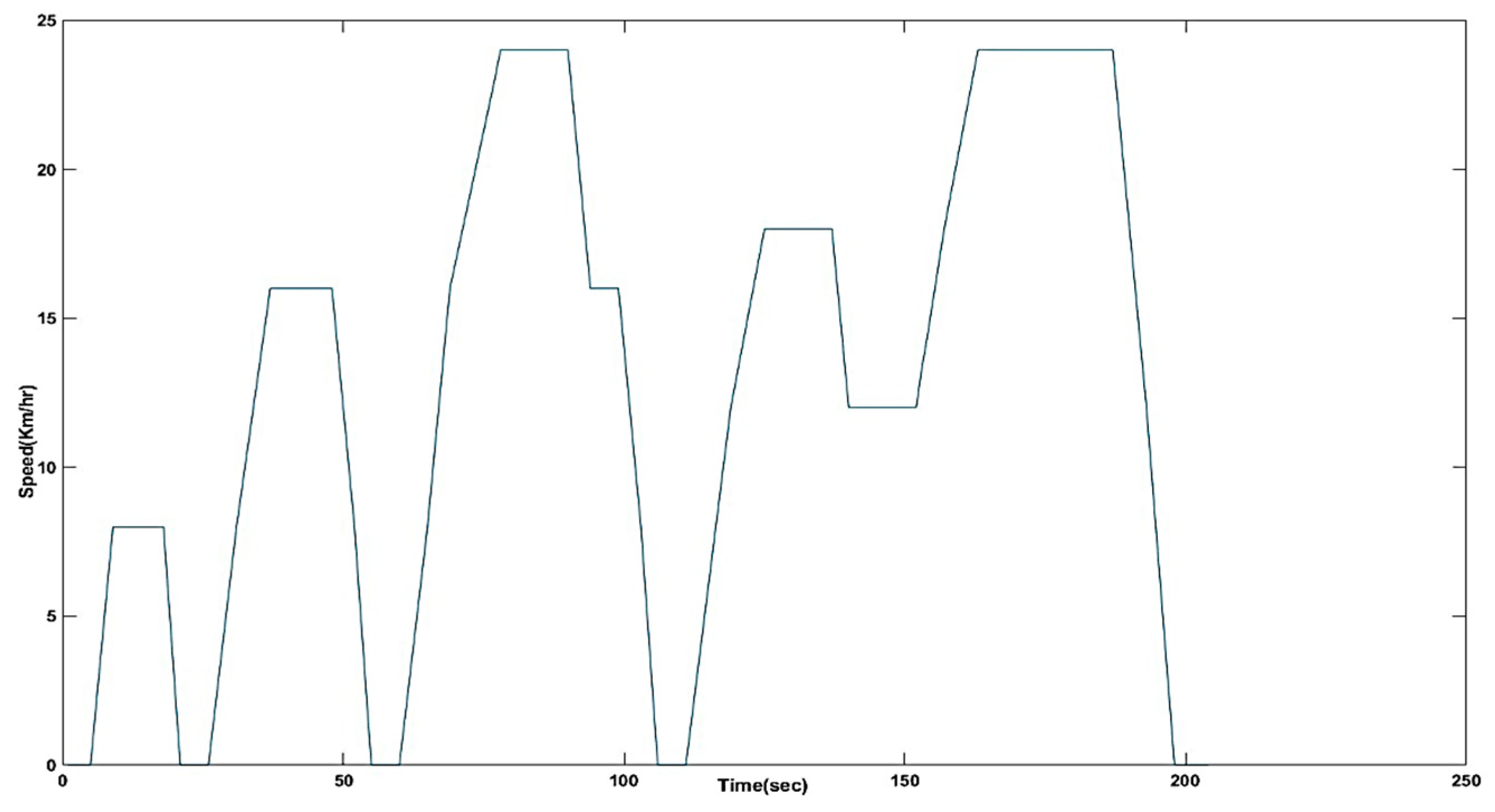
A drive cycle conveys how the vehicle is driven; it standardizes the driving pattern. A drive cycle needs to be standardized so that different vehicles can be tested and compared. Two-wheeler vehicles, small cars and buses may have their own drive cycle, and each city and town may have its own drive cycle. Usually, climbing down a slope is not a part of drive cycle, a hill terrain drive cycle should include their own drive cycle. Different countries have different drive cycles based on how the vehicles are driven in the country, drive cycle is defined for limited time tests, with measurements taken over multiple cycles. The concept of similar drives are based on various regulators, which define some standard drives, and to obtain the performance of a vehicle as per the concept of drive cycle, the power required, maximum torque required, energy required and the energy efficiency WH/km must be known. The IDC (Indian Driving cycle) was the first driving cycle formulated for vehicle certification for emissions and safety [
16]. The IDC does not cover the complex driving conditions observed on the Indian roads.
Figure 3 shows the modified Indian drive cycle used for analysis in this paper, as suggested by researchers from IIT Kanpur [
16]. The drive cycle is 204 s, and the maximum speed is 24 km per hour. This driving cycle also includes idling period, steady speed period, acceleration period and deceleration period. The angular velocity of the wheel in m/s can be converted into rpm by the formula given below:
Velocity in m/s can be converted into km/h by the formula given below:
The angular velocity of the wheel in km/h can be converted into rpm by the formula given below:
- E.
ANN-based Controller
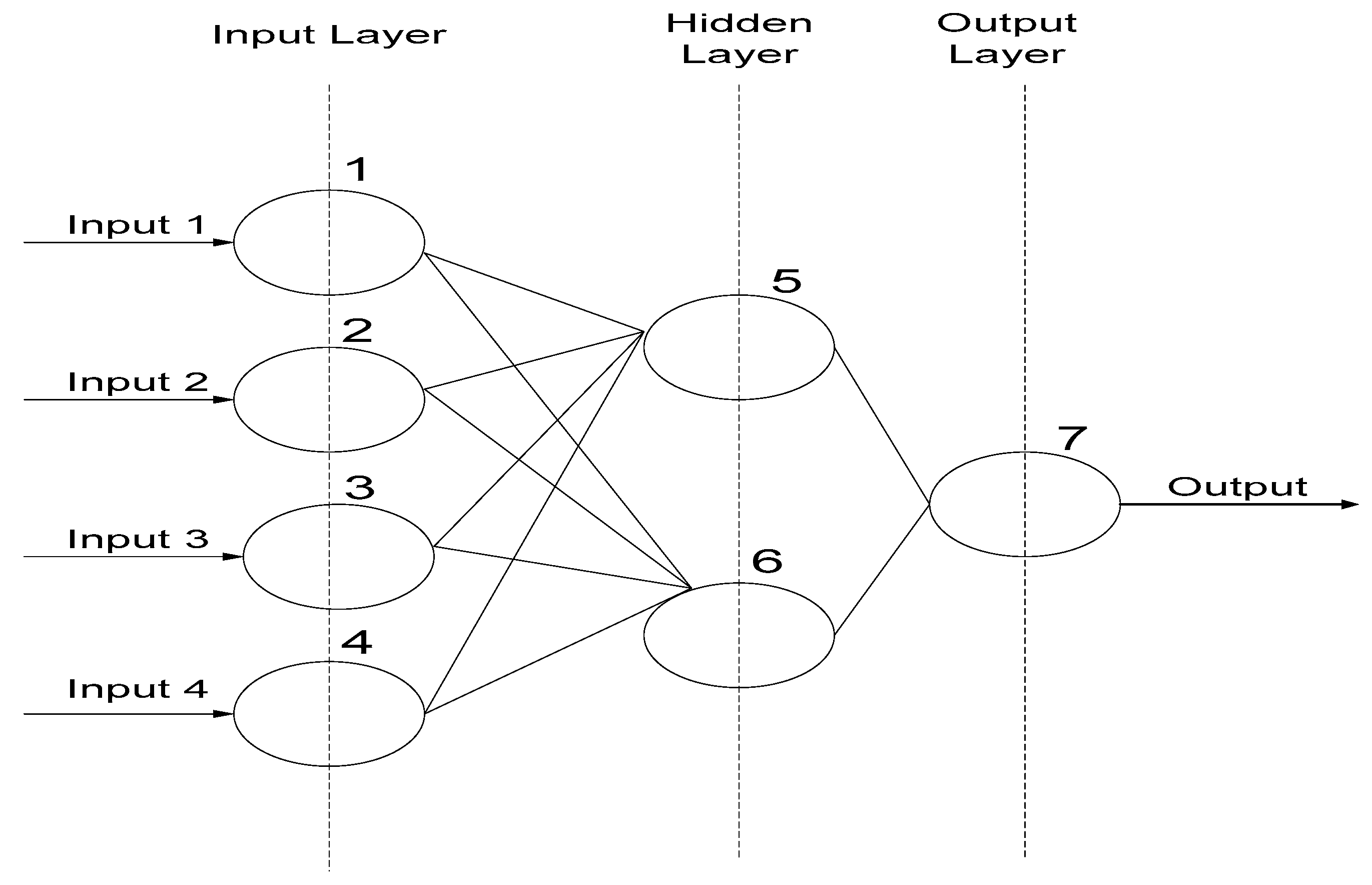
Figure 4 below depicts the controller’s multilayer feed-forward artificial neural network. It comprises an input layer, an output layer, and a concealed layer in between. There are nodes in all levels; the number of nodes present at the output and input matches the number of signals present at the output and input, and there are no constraints on the number of nodes in the hidden layer since it is independent of the number of input and output signals present. In this paper, the number of hidden layers chosen is two and the number of input and output is equal to one as the PI controller has only one input and one output, so the number of nodes at input and output are equal to 1 and the number of nodes in hidden layers are equal to five. Weight w determines the strength of the connections between nodes in various levels; weight 0 implies that no link exists. The ANN controller is trained using the data from the standard PI controller’s input and output.
The learning process of ANN is carried out via error corrective learning in this paper. ANN output is matched to the intended value of target in error correction learning, and the error can be calculated by the output difference and is used to change the weights of ANN. At each training iteration, the error correction learning algorithm tries to reduce the error signal. The backpropagation method is the most widely used learning algorithm. ANN can determine the relationship between the input and output data without knowing the precise function. To train the ANN, the data transferred from the input and output data of the PI controller to the workspace from the Simulink can be achieved by applying the simout. After the regression is equal to or close to one, and when it reaches the desired mean square error that is set before training ANN, Simulink block of ANN is generated, and then PI controller is replaced with an ANN-generated block to validate and compare the proposed scheme.
MATLAB syntaxes used to train the ANN are given below:
I = in’;
T = out’;
net = newff(minmax(I), [1,5,5,1], {‘logsig’,’tansig’,’tansig’,’purelin’},’trainlm’);
net = init(net);
net. trainParam.show = 10;
net.trainParam.lr = 0.06;
net.trainParam.mc = 0.075;
net. trainParam.epochs = 10,000;
net.trainParam.goal = ;
net = train (net, I, T);
Data Input is denoted by I, target value is denoted by T, an artificial neural network denoted by net, newff denotes a new feed-forward neural network, and minmax(I) denotes the minimum and maximum value of the input data to determine the minimum and maximum input range for training. The number of nodes at the input layer, each hidden layer, and the output layer are (1,5,5,1), correspondingly. The activation functions for input, hidden, and output layers are called logsig, tansig, and purelin, respectively. Purelin is a pure linear activation function that is often employed in the output layer, and trainlm is a Levenberg–Marquardt backpropagation training technique that is utilised flexibly depending on the needs of a task. net = init(net) signifies ANN is initialised with the input, output data, and hidden layers, net. trainParam.show = 10 is used to display the state of the network’s training after a 10-epoch interval, net. trainParam.show = 10 is used to display the status of the network’s training after a 10-epoch interval, and net. trainParam.lr is used to indicate the learning rate, whereas net.trainParam.mc is used to specify the momentum. The number of iterations is represented by net. trainParam.epochs; epochs typically indicate iteration. The purpose of net. trainParam.target is to reduce the error to 10(−5), and net = train (net, I, T) is to begin training using input and output data.
When the regression value equals one (R = 1), the ANN is trained, and the trained ANN is moved from the workspace to Simulink. The MATLAB syntax is genism (net, −1), where net is the name of a trained ANN and −1 is a sampling period, which is used as −1 for continuous-time simulations.
3. Simulation Results and Discussion
This section presents the simulation result of PMSM drive employing FOC with current-based MRAS sensorless speed estimation scheme.
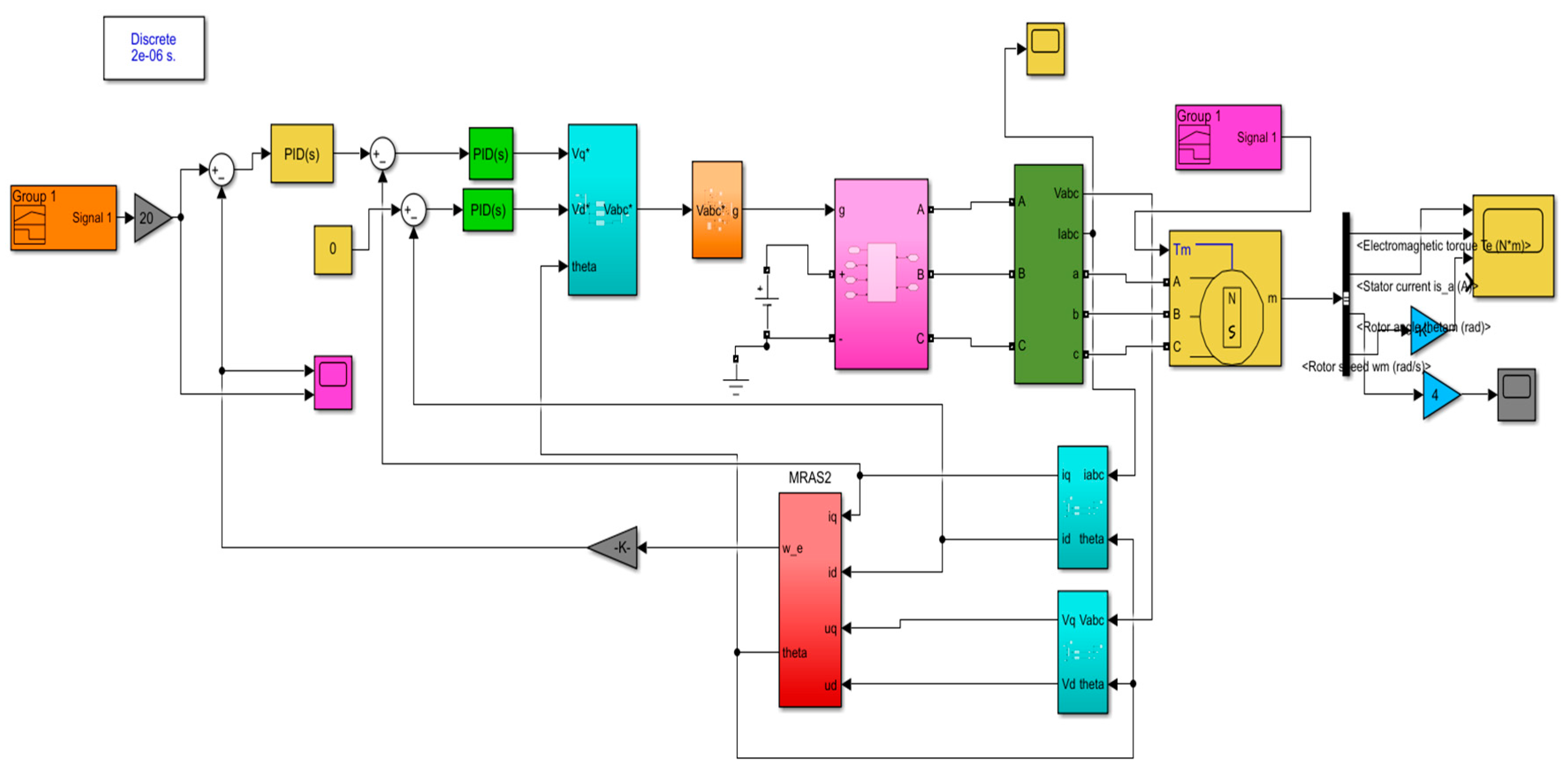
Figure 5 shows the simulation developed in the MATLAB environment.
Table 1 shows the simulation parameters used for analysis.
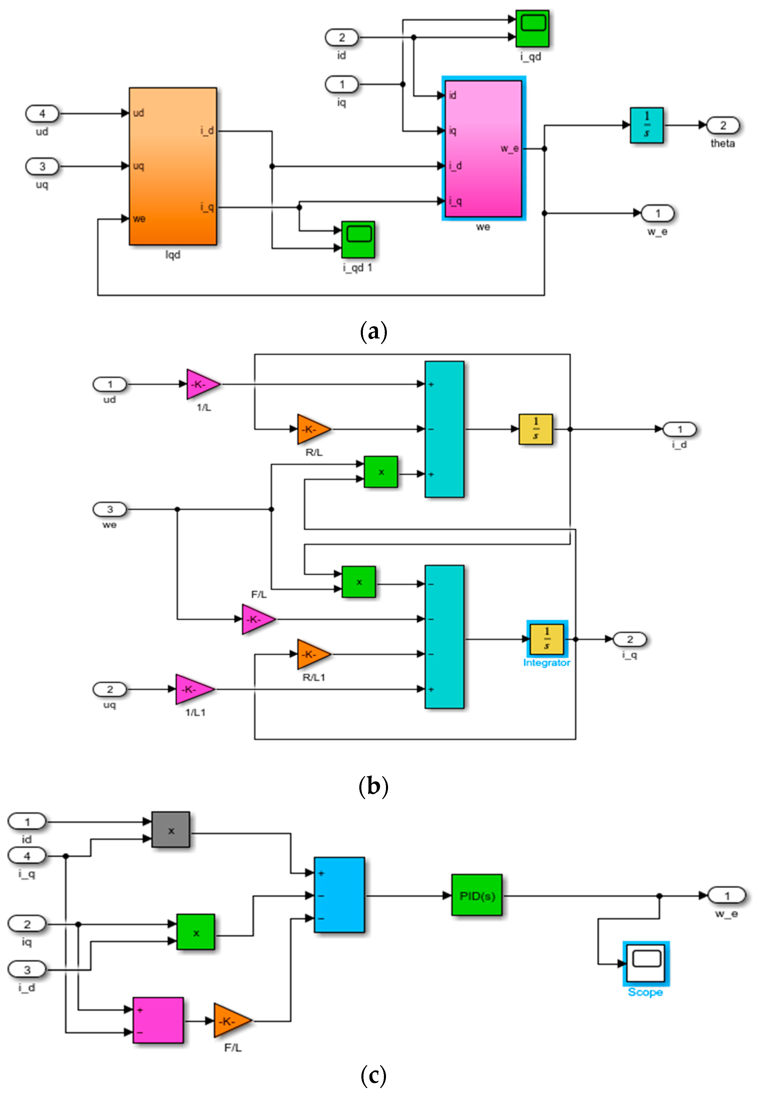
Figure 6 shows the in detailed current based MRAS sensorless speed estimation scheme, and
Figure 7 shows the simulation results for the developed current-based MRAS scheme of the PMSM drive.
Figure 5 shows the MATLAB/Simulink snapshot of the PMSM speed control. DC power source is used as the power source for the drive connected through the converter. The MRAS block of the simulation is further displayed in
Figure 6 as detailed current-based MRAS scheme. It consists of estimation process of speed from reference and actual current values in
Figure 6a, estimation of actual current signal in
Figure 6b and estimation of speed from actual and reference current value errors in
Figure 6c using PI controller. In
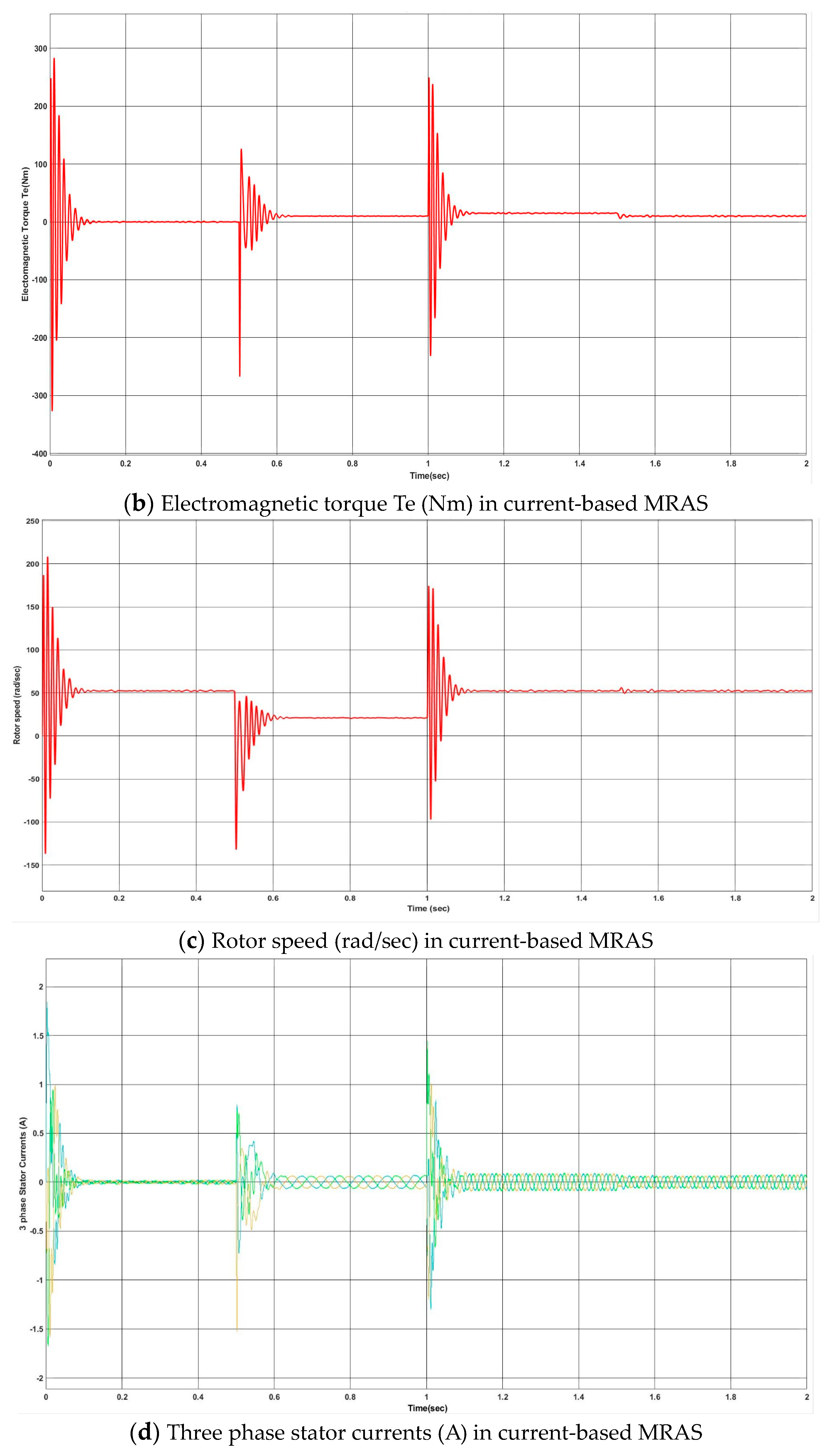
Figure 7, the various simulation results are presented, such as rotor speed, torque, and currents.
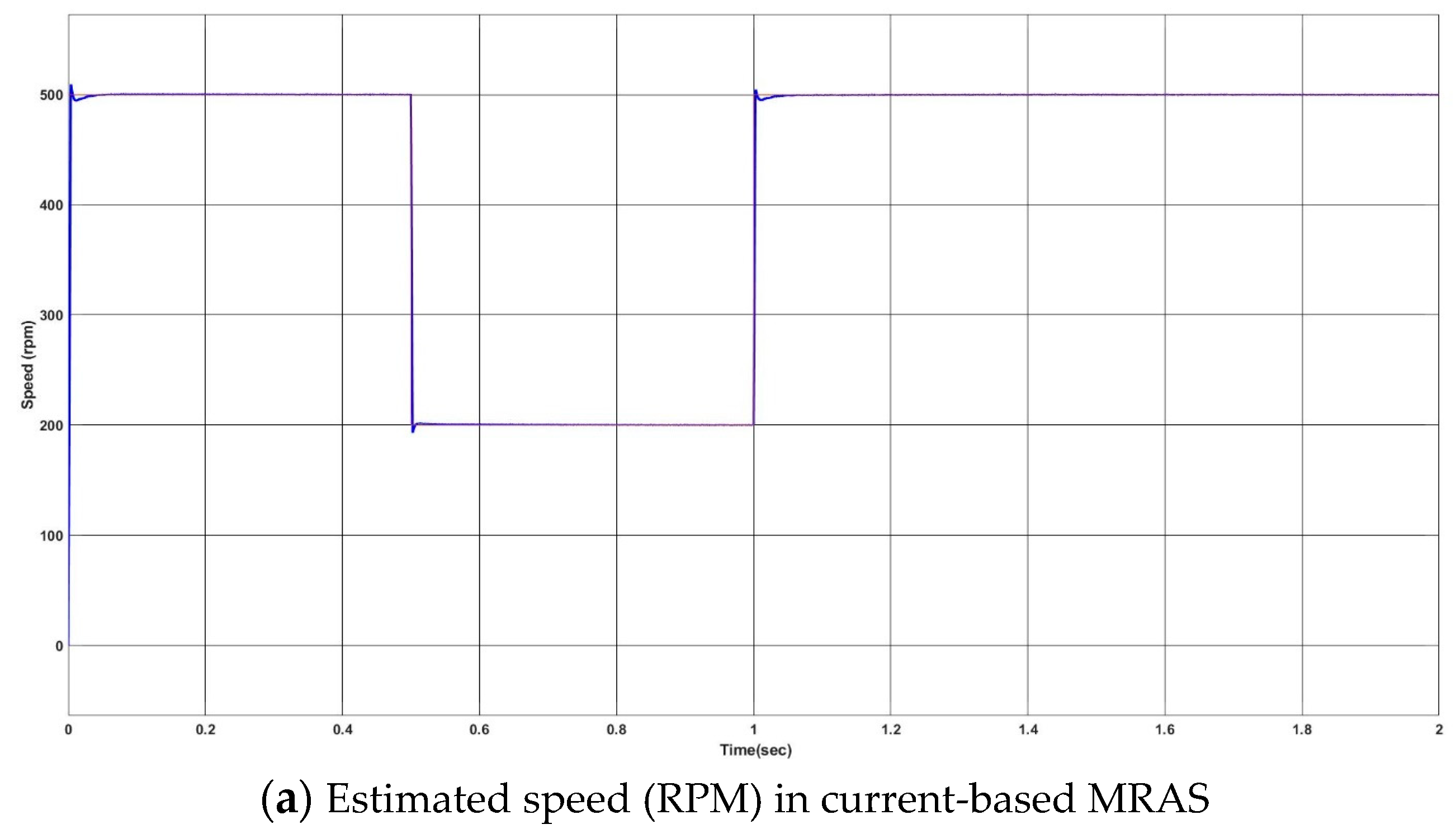
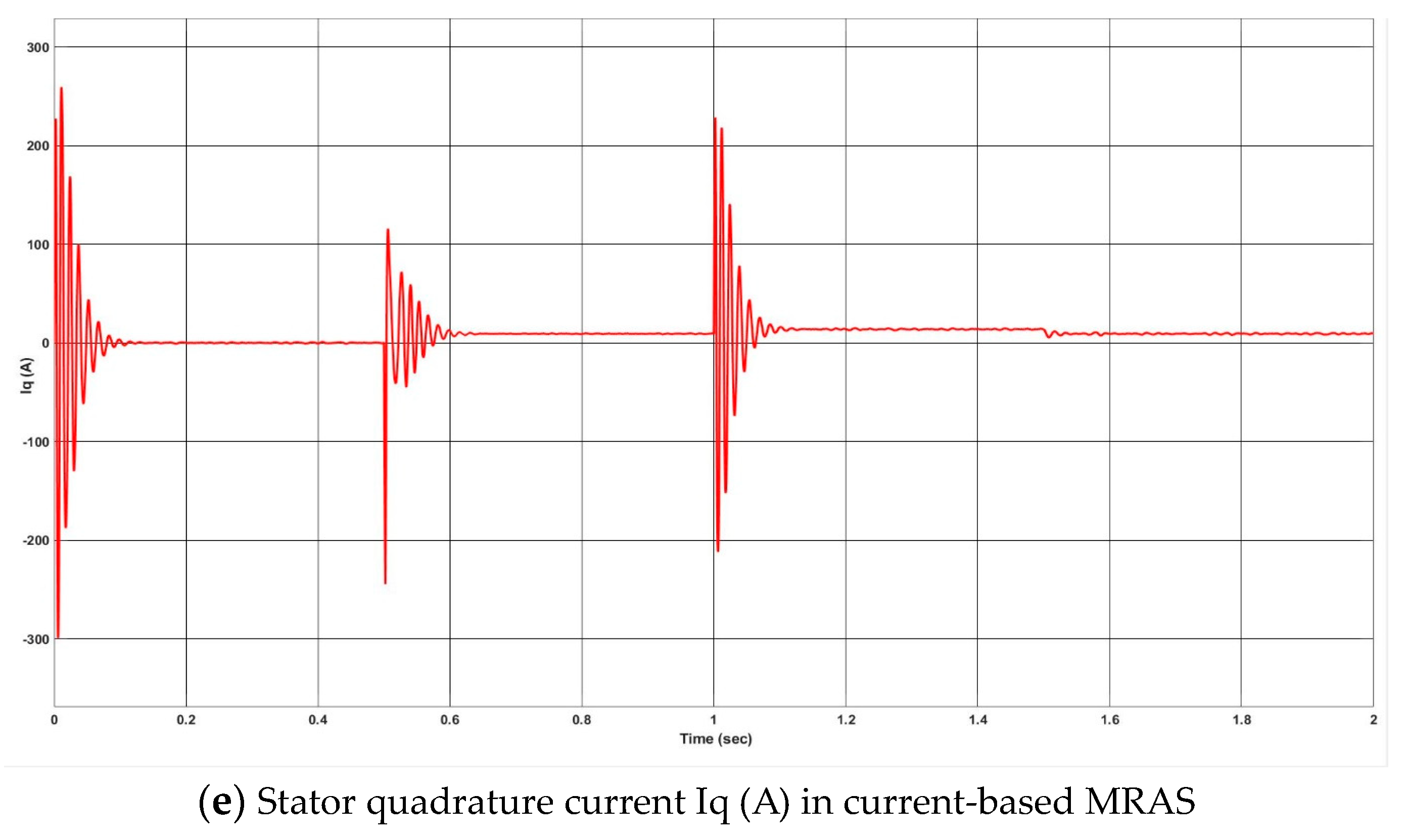
To validate the developed simulation, the reference speed is changed from 500 to 200 to 500 rpm at 0-0.5-1 s, respectively. The corresponding results of rotor speed, torque, and currents from
Figure 7 validate the MATLAB Simulation for the current-based MRAS, which works perfectly fine for the reference speed. As the reference speed changes, correspondingly the estimated speed, current and torques change to reduce the error developed by MRAS block.
Next, an Indian drive cycle ( as seen in
Figure 3) is applied to the developed simulation for the speed estimation by current-based MRAS, as shown in
Figure 8.
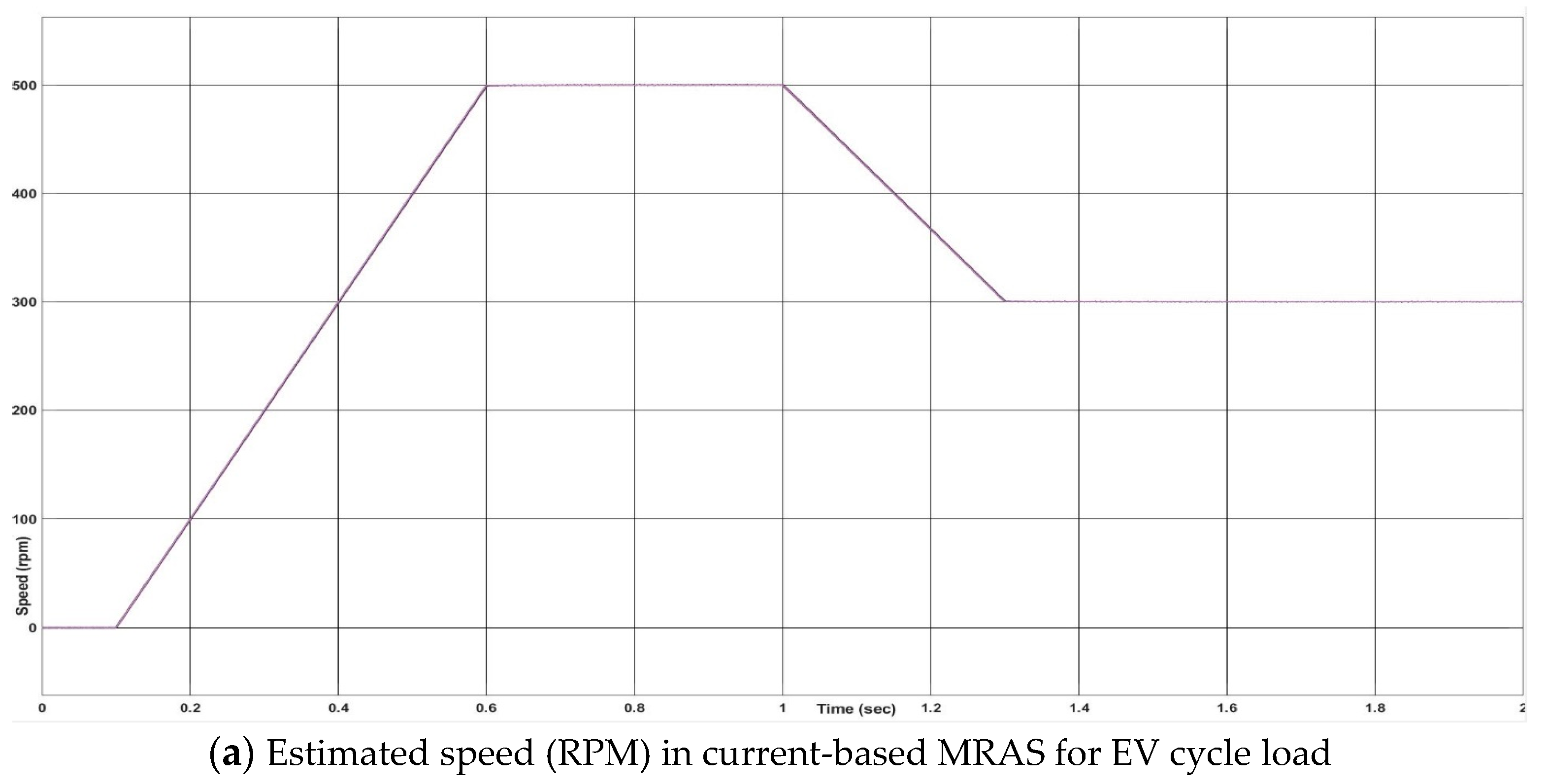
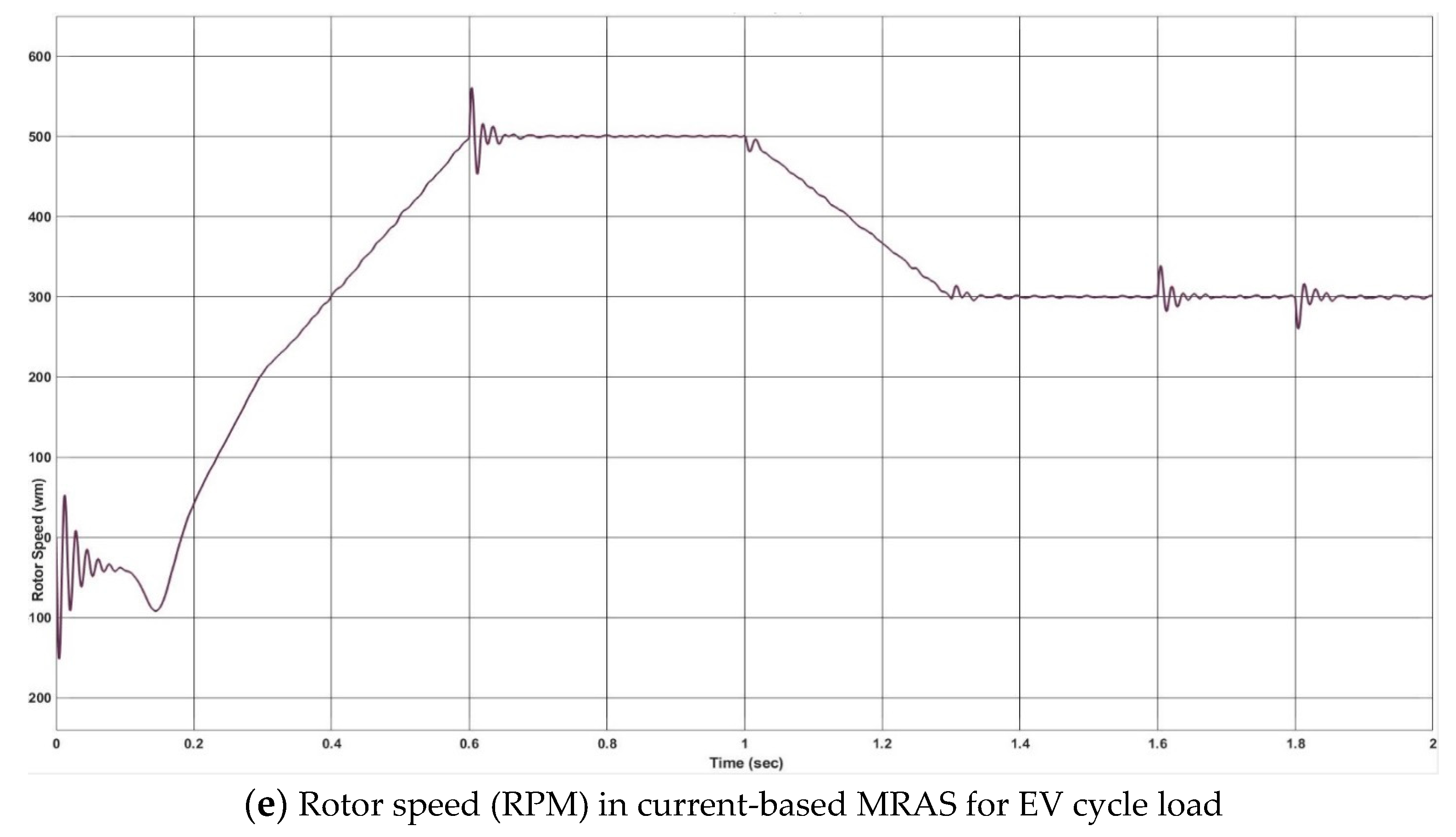
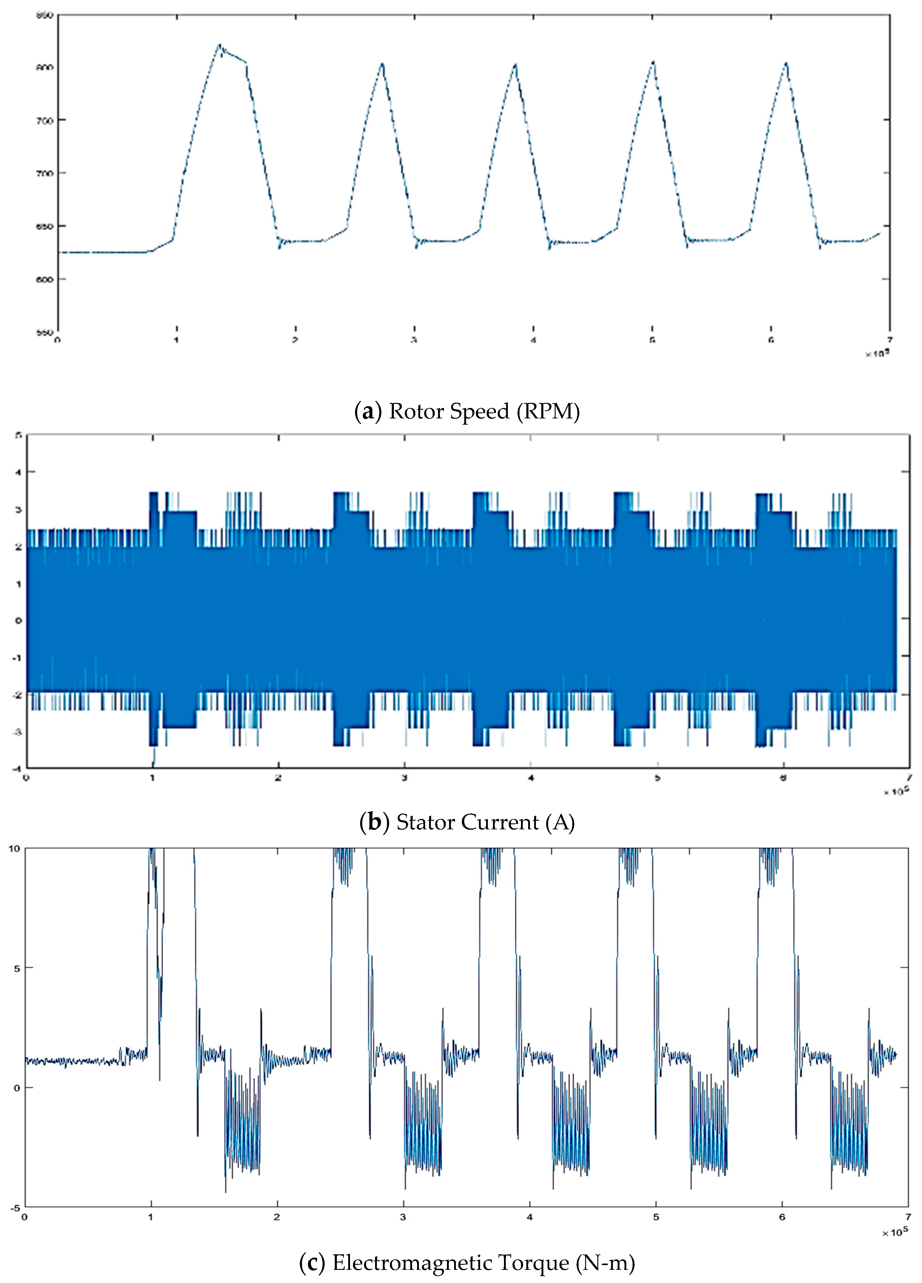
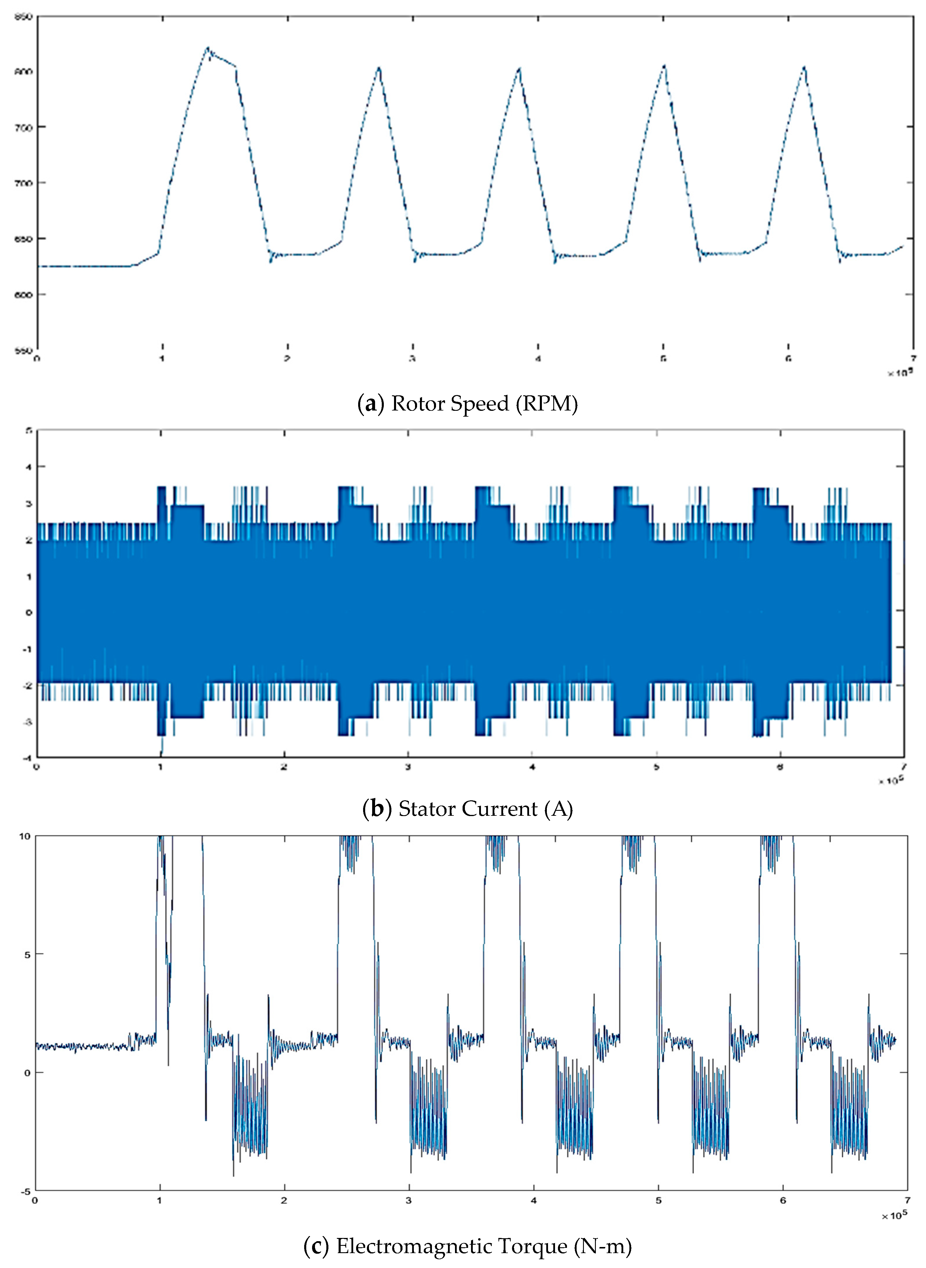
In
Figure 8, initially for 0.1 s the vehicle stalls, after that it accelerates achieving the maximum speed of 25 km/h at 0.6 s. From 0.6 s to 1 s, the EV is travelling with a steady speed and then starts decelerating at 1 sec, and the speed reaches 15 km/h at 1.3 s, then again, the EV travels at 15 km/h till 2 s.
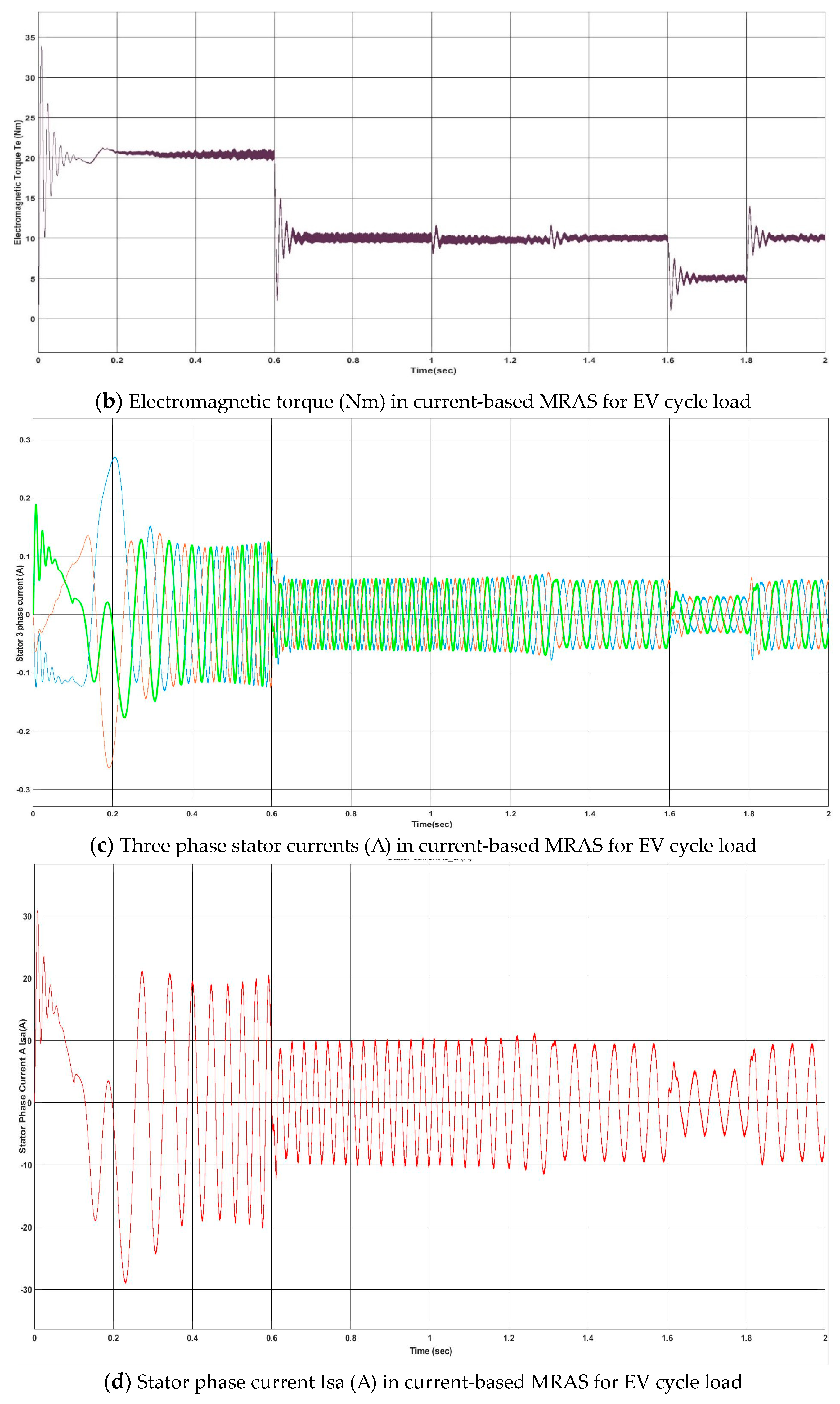
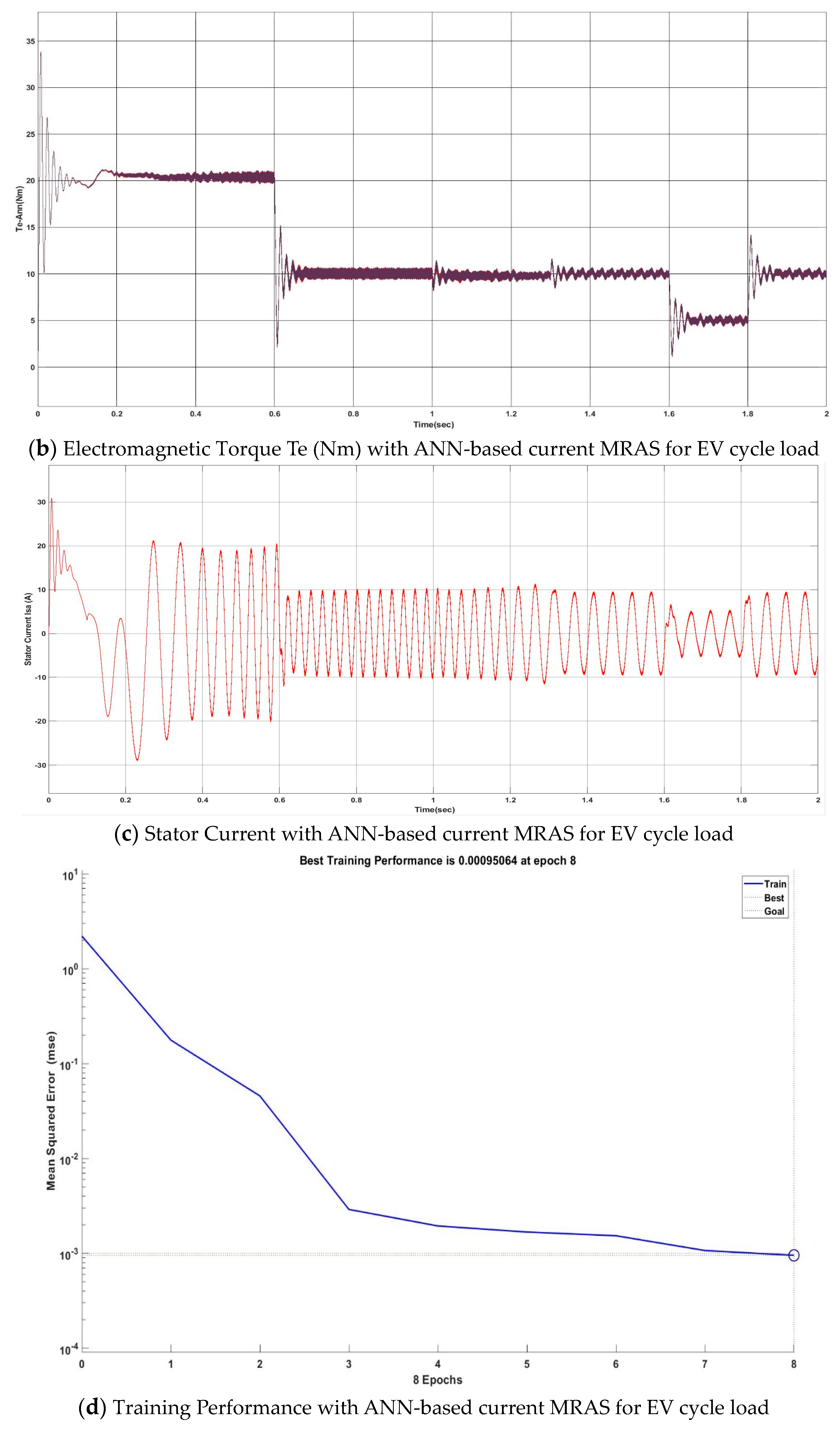
Figure 8a shows that the estimated speed (RPM) in current-based MRAS for EV cycle load is properly obtained and is the desired output as per EV cycle. The stator three phase current varies according to the load applied, initially, at 0 s, the torque applied will be maximum because initially the resistance will be greater, and the torque applied will be maximum till it reached maximum speed. At 0.6 sec the torque will be reduced from 20 Nm to 10 Nm and at 1.6 s the torque is reduced further to 5 Nm till 1.8 s; while this time speed remains constant at 300 rpm, this region shows the constant speed mode of a drive.
In the above two cases discussed, the controller used is PI. However, in real-time parameter changes due to temperature change and Kp, Ki value will not change itself; hence, an ANN-based controller can be used in place of a PI controller. Before replacing the PI controller with the ANN-based controller, ANN has to be trained with the help of the PI controller input–output data, as discussed in
Section 2.
Figure 9 above shows the MATLAB Simulation for current-based MRAS controller using the ANN technique. To tune the ANN, mean square error is set to 10
−3 and the training method used is Levenberg–Marquardt backpropagation.
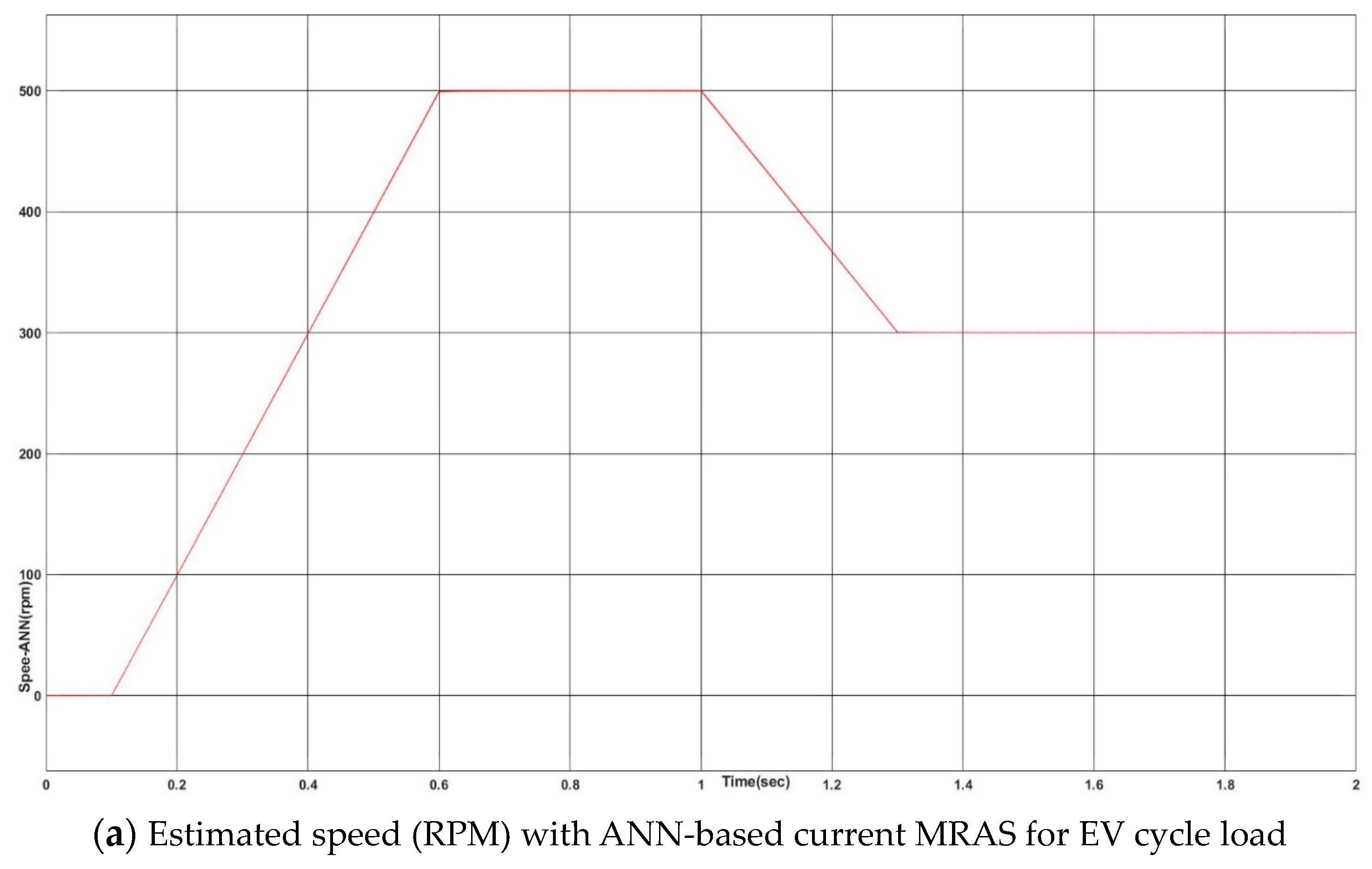
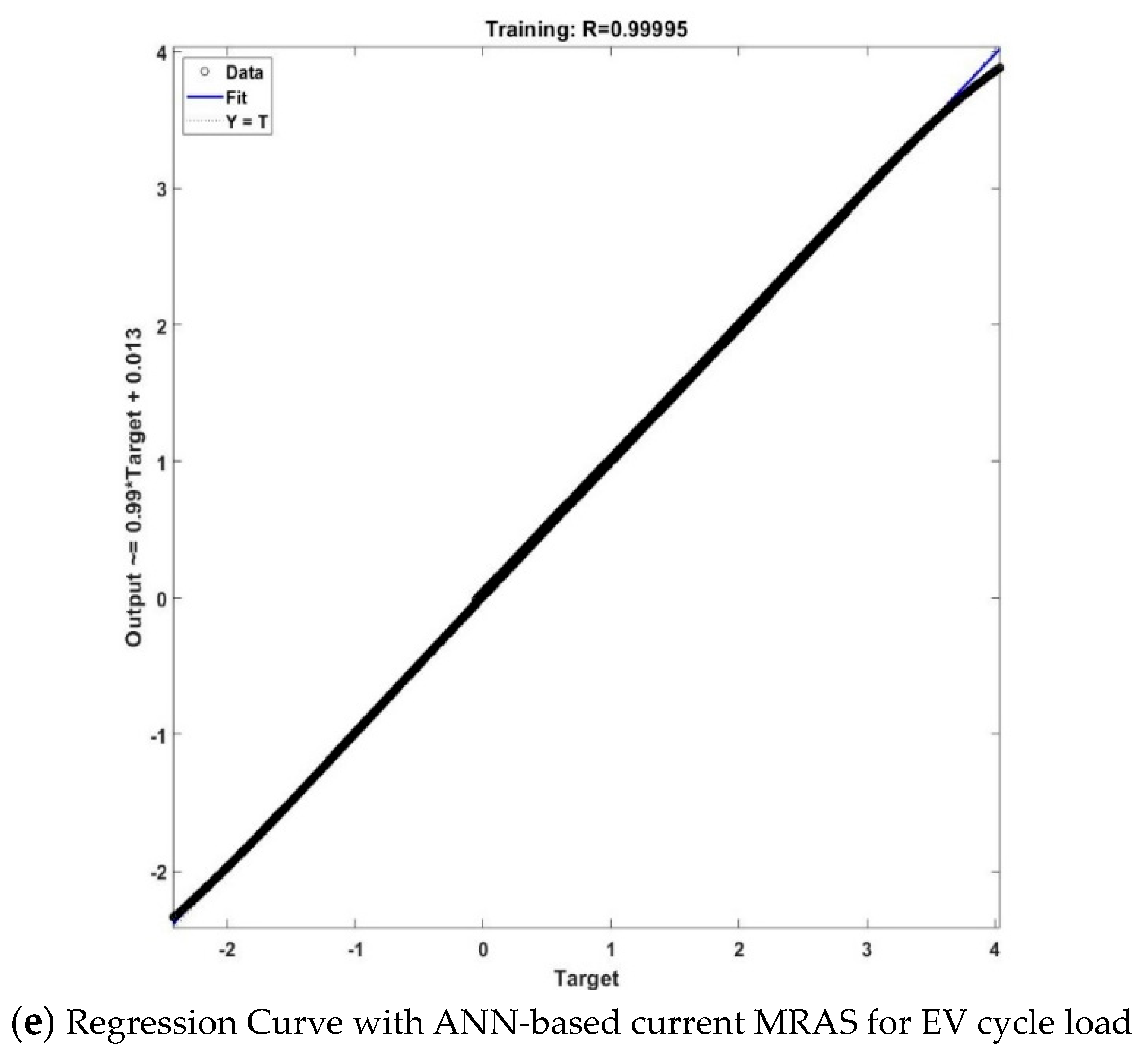
Figure 10 shows the corresponding results and in
Figure 10d, the mean square error reached 10
−3 after eight epochs (epochs means total number of iterations) and the regression curve (
Figure 10e) reached 0.99995, which is approximately equal to 1, meaning the ANN-based controller is trained.
Figure 10 shows that after replacing the PI controller with the ANN-based controller, the speed tracked is comparable to the speed with PI controller, and hence, it validates the smooth training of the ANN-based controller.


