Abstract
The current sensorless vector-controlled permanent-magnet synchronous motor (PMSM) drive using a single sensor (i.e., speed sensor) is presented in this work. The current sensors are removed, and the estimated currents are used to close the current loop to minimize the drive cost and make it fault-tolerant against current sensor failure. A classical vector-control PMSM drive requires at least three sensors, i.e., two current sensors and one speed/position sensor. This paper presents a new current estimation technique that is free from inverter switching states, an integrator, and differentiator terms. The drive is suitable for retrofit applications, as it does not require any additional hardware. The reference voltages () are used to estimate the rotor reference frame currents (i.e., ). The presented algorithm depends on the stator resistance (). The online estimation algorithm is used for compensation to overcome the effect of the on the estimated currents. The sensitivity analysis for the currents against the speed is verified and presented. The speed loop is closed with actual speed information, which will try to maintain the reference speed under any circumstances. The proposed current sensorless PMSM drive was validated using MATLAB/Simulink and also verified on a hardware prototype. The presented technique was verified for various operation conditions, and some of the extensive results are presented.
MSC:
70Q05
1. Introduction
PMSMs (permanent-magnet synchronous machines) have been gaining a strong interest over the past decades. Its unique characteristics meet the electric vehicle drive operation criteria, with a higher torque/inertia ratio and minimum copper losses with high efficiency, and the PMSM operates successfully at the required speed and load [1]. A PMSM is smaller in size compared to other machines [1]. Vector-control drive has an excellent dynamic performance [2]. The speed/position data are accessed from a sensor attached to the machine shaft for controlling the drive. In general, a three-phase PMSM requires at least two phase currents and rotor position information to compute the rotating reference frame currents [1,2].
Torque ripple in the drive operation can be caused by sensor parameters, such as gain errors, drift, and offset, resulting in poorer performance [3]. The failure of the sensor occurs under heavily loaded conditions and high ambient temperature, which results in drive instability. The decrease in the sensors in the drive will lower the failure rate, increase the reliability, and reduce the cost of the drive.
This paper mainly concerns the reduction of the sensor’s dependability (i.e., current sensors), increasing the drive reliability, and making it fault-tolerant. In the literature, current sensor reduction/elimination is discussed. This section starts with a brief overview of the various current estimating techniques for current sensor reduction, and then it is carried out with the proposed estimation technique.
In the literature, there are a few single-current sensor-based drive approaches. Based on the placement of the current sensor in the inverter, the reconstruction of three-phase currents is divided into a DC-link current measurement, measuring multiple branch current measurements with a single current sensor, and a single-phase current measurement [4,5,6,7,8,9,10,11,12,13,14,15,16,17,18]. Three-phase currents are reconstructed based on the DC-link current, voltage, and inverter switching information [8,10,19,20,21,22]. Although DC-link current measurement is a common strategy, it has certain drawbacks: low modulation index, active-switching states at the sector boundary/short duration, and phase variation in the estimated currents, which are all factors to consider. A few solutions for enhancing the phase current accuracy in the reconstruction in all four-quadrant regions have been given in the literature. Under the zero-voltage vector sampling zone, an isolated current sensor technique is used to detect phase currents matching the DC-link current [4]. The measurement vector insertion approach was adopted to overcome the difficulty of switching states in a short period [23]. In [16], it shows how to measure phase currents in a low-modulation index or a near-sector boundary region. These approaches rely on the DC-link current and inverter switching states to reconstruct the phase currents and require an extremely complicated analysis.
A current sensor is used to measure the current passing through multiple branches [4,5,6,9,10,12]. The three-phase currents are reconstructed using the advantage of switching states and the sum of the branch currents. In this method, a current sensor is employed to measure more than the rated current [12], which increases the current sensor’s cost.
The estimation of the current without using a DC-link current sensor is presented in [21,24,25,26,27,28,29,30,31]. These methods use either a speed encoder/voltage sensor/single-phase current measurement and an accurate machine model to estimate the currents. The current sensor detects the single-phase current, and using an observer design approach, the remaining phase currents are estimated [32]. The PMSM drive current sensorless procedure makes the drive more robust, cost effective, and reliable. References [25,33] present a PMSM drive prediction approach based on a current sensorless extended Kalman-filtered operation. This approach is mostly machine-dependent and involves both the initial conditions and filters.
A new technique is presented for current estimation with a low precession speed/position sensor for a PMSM drive. In the frame, the current estimation was constructed on machine formulae. The dead-time was employed to make the delay caused by the machine and inverter in real time. This process was simulated in MATLAB/Simulink and verified for various conditions and verified for a four-quadrant operation.
To overcome the drawbacks in the existing methods, the paper presents a new method for a current sensorless approach. The proposed method has several advantages. As it does not require any additional sensors or hardware, it makes the drive suitable for retrofit applications. The current estimation technique can be used to monitor the status of current sensors by implementing them in the existing PMSM drive. A speed sensor was employed to perform the drive operation, and the current estimation technique reduces the drive cost and complexity. The reliability and immunity to signal noise are increased, as a single sensor is used, i.e., speed/position sensor. The proposed drive is independent of the switching states, an integrator, and differentiator terms.
- ➢
- A current sensorless algorithm for a PMSM drive;
- ➢
- An algorithm that is independent of an integrator and differentiator terms;
- ➢
- The algorithm can be applied with a low-resolution speed sensor;
- ➢
- The overall drive cost can be reduced for low-precession applications;
- ➢
- Has a reduced current sensor dependency;
- ➢
- The proposed current estimation method can be used to make the existing PMSM drives (which use all of the current sensors) fault-tolerant against failure of the current sensors.
The following is a summary of the structure of the paper. In Section 2, the modeling of the PMSM is discussed. Section 3 explains the mathematical model of the current estimating scheme. In Section 4, a sensitivity analysis is performed and presented. In Section 5, the proposed drive is validated using the MATLAB/Simulink platform, and the results are provided to show the performance under various conditions. On the dSPACE 1104-based laboratory prototype, the current sensorless PMSM drive is validated, and the results are presented in Section 6. Finally, in Section 7, this work is concluded.
2. Modeling of PMSM
Reference [1] was used to model the PMSM machine. The stator currents (i.e., “” and “”) in the rotor-reference frame for the PMSM are shown in (1).
The electromagnetic torque is expressed as shown in (2). The electromechanical dynamics equation is shown in (3). ( and the machine was a nonsaliency type with a sinusoidal back—EMF waveform, where and are the electric-torque and load-torque, respectively. Table 1 shows the PMSM machine’s parameters.

Table 1.
Machine parameters.
3. Current Sensorless Methodology
In the “” and “” frame, the proposed method estimates the currents using the machine modeling in Equation (1). In the rotor reference frame, the stator voltages were defined as in (4) and (5), where show the actual ; show the estimated ; and represent the reference currents.
Under a steady-state operation, the differential terms are considered as zero.
taking from in for (6) and in for (7). The currents on the are calculated and presented as .
Figure 1 shows a flow chart for the proposed current estimation method. From Figure 1, the outer speed loop from the motor speed sensor maintains the voltage gains to maintain the estimated currents in a closed loop.
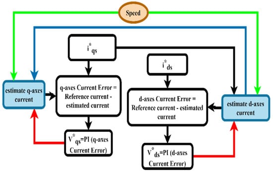
Figure 1.
Flow chart for the current estimation method.
4. Sensitivity Analysis
In this secession, the sensitivity [34] of the estimated currents against variation was performed. The and are considered as the sensitivity indicators, and and are plotted against the speed variation.
These are the transfer functions of the PI controllers of the speed loop and the q axes and d axes current loops.
, , and are stated in (11), (15), and (21), which are taken from Figure 2 and (10).
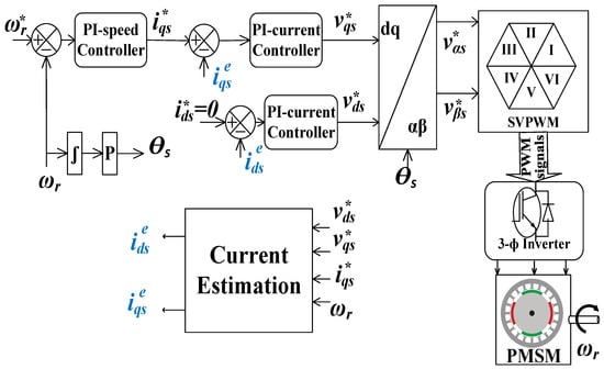
Figure 2.
Schematic diagram of the speed sensor vector-controlled PMSM drive with the current sensorless scheme.
is expressed as
is expressed as
From (17) and (18)
is expressed as
Using a small-signal analysis, the expressions for and become:
is expressed as
where
is expressed as
The sensitivity plot for the estimated currents is shown in Figure 3 for the variation. Figure 3a presents with respect to the variation. Figure 3b presents with respect to the variation. The performance of the estimated current is presented with the speed (). The sensitivity is shown for the motoring and regenerating mode operation range with a 10 N·m load. The outer loop was closed with the actual speed information from the sensor; thus, the drive stabilized itself to maintain the shaft speed at the reference speed.
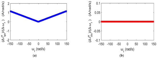
Figure 3.
Sensitivity plot: (a) with respect to the variation; (b) with respect to the variation.
5. Simulation Results
This work presents a position or speed sensor-based vector-controlled PMSM drive for the current sensorless scheme. A schematic diagram is shown in Figure 2. References [1,2] present the switching sequence, vector-control, and mathematical model for the PMSM drive. Under various operating speeds/loads, the PMSM drive with the current sensorless algorithm was modeled and tested in MATLAB/Simulink, and some of the results are demonstrated to show the performance of the PMSM drive. The speed loop was closed using data acquired from the speed sensor, while the currents were closed with the estimated quantities. Table 1 shows the machine’s parameter obtained from a laboratory prototype of the PMSM machine.
The actual currents and the estimated currents are shown in the rotor-reference frames. denotes a successful vector-control operation, whereas denotes the torque-producing current component. The simulation plots the shaft speed () against the reference speed (), and the position is displayed.
The drive performance is presented for the various reference speed commands, and the simulation results confirmed the performance of the proposed method. The drive was verified for the ramp speed command, step speed command, and four-quadrant operation. To check the accuracy of the estimated values, the actual currents, reference currents, and estimated currents are shown on the same graph in the simulation results.
5.1. Various Speed Operations
The current sensorless PMSM drive was evaluated for various speed operations, and the simulation results are presented in Figure 4. The current sensors were used to observe the actual currents and verify the estimation technique performance. The estimated current followed the actual currents observed from the simulation results presented in Figure 2. To demonstrate the accuracy of the current estimation technique, the estimated and the actual currents are plotted on the same scale in Figure 4.
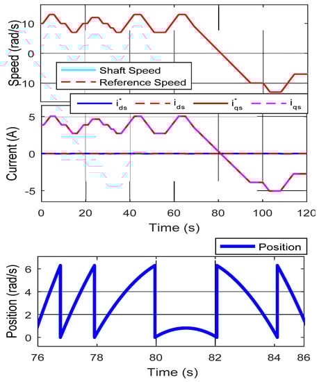
Figure 4.
The drive was tested for the forward motoring and reverse motoring operations for various speed commands.
5.2. Drive Performance for the Ramp Speed Command
The drive was verified and tested for the ramp command, and the results are shown in Figure 5 under varied load and speed circumstances. The tracking performance was tested for the ramp-type speed (i.e., slow zero crossings). The reference speed was changed in a slow ramp command with +10 to −10 rad/s. The PMSM was connected with the DC generator-type load (i.e., load). The was maintained at zero, reflects the q-axes vector-control operation. The estimated and actual torque-producing stator current components are presented on the same scale. The current estimation technique’s performance is shown in Figure 5 for the ramp speed command and slow zero crossings.
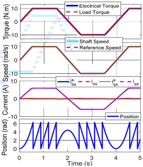
Figure 5.
The drive was tested for the forward and reverse motoring operations for the ramp speed commands.
5.3. Drive performance for Step Speed Command
The simulation results for the proposed technique for the step speed command are illustrated in Figure 6. Initially, the reference speed was set at ten rad/s, and the speed was altered between ±10 rad/s. The DC generator-type load (i.e., load) was acting on the PMSM. It was observed that the estimated and actual stator currents were comparably similar. The estimated currents and actual currents are shown on the same scale to demonstrate the accuracy of the proposed current estimation technique.
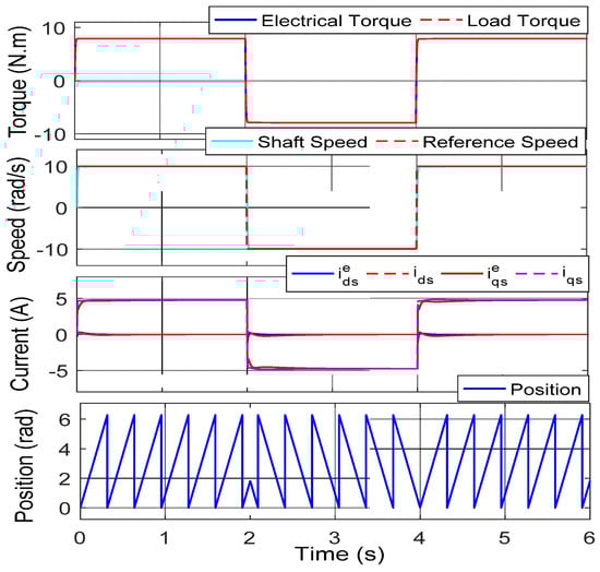
Figure 6.
The drive was tested for the forward motoring and reverse motoring operations for the ramp step commands.
5.4. Drive Performance for the Four-Quadrant Operation
Figure 7 shows a four-quadrant operation. The machine was initially set to +10 rad/s and 8 N·m. The reference speed was changed from +10 to 0, −10, and +10 rad/s at t = 2, 3, and 6 s. The load was changed within ±8 N·m at t = 4 and 7 s.
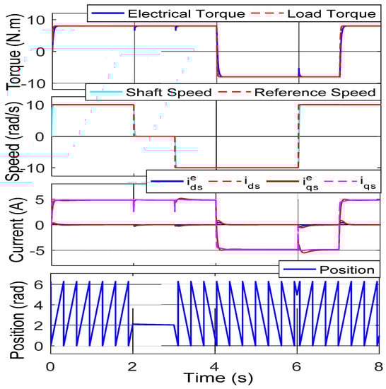
Figure 7.
The drive was tested for a four-quadrant operation for the step command.
The PMSM was coupled with a DC motor, and for the first two seconds, the torque and speed were both positive, resulting in the first quadrant operation. The DC motor produced the torque in the same direction as the PMSM. In the simulation results, a zero-speed operation with a positive load was demonstrated.
From t = 2 to 3 s, the DC motor pushed the PMSM machine and acted as a generator until the speed was negative and the torque was positive. From t = 4 s to t = 6 s, the torque was negative, and the speed was negative, resulting in the third quadrant reverse motoring action. From t = 6 s to t = 7 s, the torque was negative, and the speed was positive, resulting in a second quadrant operation. The DC motor pushed the PMSM machine, which acted as a generator. The position information provides the accuracy of the presented algorithm for a zero-speed and four-quadrant operation.
5.5. Effect of the Stator Resistance ()
The method was tested for the parameter change, and the simulation results are displayed in Figure 8. The current loop was closed with the estimated d and q axes current quantities. The machine resistance was varied with +0.2 ohms from t =10 s to t = 12 s. The effect of the parameter variation was observed on the vector-control (as ), and the simulation results are given in Figure 8. The estimated and the actual currents were affected from t = 10 s, with the variation effect. Therefore, the drive requires the estimation algorithm with compensation to avoid the impact of the machine’s parameters.
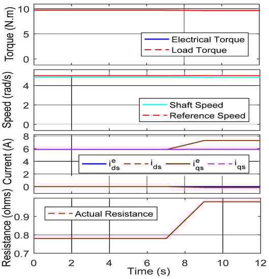
Figure 8.
The drive was tested for the stator-resistance variation.
5.6. Stator Resistance Compensation
The procedure was verified for the variation with online estimation [34] and compensation. The algorithm failed to estimate the actual currents under variation. The online estimation algorithm was used to estimate and compensate for the current estimation algorithm. The machine was loaded with the load. The speed command was changed in a ramp form and maintained constant at five rad/s. The was estimated and compensated in the current estimation algorithm at t = 5 s. At t = 10 s, the was changed in a ramp form with 0.22 ohms, and the simulation results are given in Figure 9. Figure 9 confirms the satisfactory results for the estimation and compensation to the current estimation algorithm.
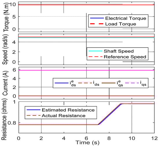
Figure 9.
The drive was tested for the online stator-resistance estimation and compensation.
6. Hardware Validation
The presented method was validated experimentally on a laboratory prototype using dSPACE 1104 (shown in Figure 10). The drive consisted of the DC generator, PMSM, inverter, driver and protection circuit, and dSPACE 1104. The current sensorless PMSM drive was verified for various conditions; some are presented to show the performance of the proposed algorithm. The experimental results show the shaft speed (), reference speed (), actual (), and estimated (), reference currents (), and the position.
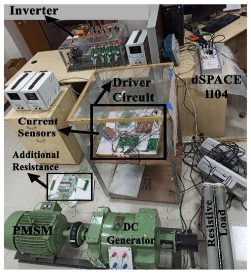
Figure 10.
Experimental setup.
The dSPACE-based laboratory interface is more flexible for verifying the algorithms and advantageous for testing in various applications, such as robotics and electric drives. The dSPACE 1104 is more suitable for a laboratory interface with a cost-effective, real-time processor with an I/O interface. The dSPACE is user friendly with MATLAB/Simulink (the Realtime Interface provides Simulink with blocks for the I/O configuration). Using the DS1104, the Simulink block was interfaced with the I/O graphically, and the code was generated for the Realtime Interface (RTI). The model was compiled and built into the DS1104 controller board connected with the PC.
The I/O signals were accessed via an adapter cable from the CP1104 (connector panel) to the DS1104 controller board. The CP1104 had eight ADCs and eight DACs, a digital I/O, a slave I/O PWM, two incremental encoders, and serial communication: RS232 and RS485. For the IPMSM drive, two ADCs were used: one for speed information and the other for the current sensor information. The controller board computed the control algorithm, and three-pulse width modulation (PWM) signals with 5 V were generated on the CP1104 (slave I/O PWM). Three PWM pulses were sent to the driver circuit board from the dSPACE-1104 PWM I/O board. Six PWM pulses of 15 V (three inverting and three noninverting PWMs) were generated using three PWM pulses. The pulses were generated with a dead band of 2 µsec to the SKYPER 32 R (SEMIKRON) driver circuit in the inverter. The Semikron driver circuit could control the IGBT (SKM75GB12T4) switching in the inverter.
6.1. Variable Speed Operations
This section shows the experimental results for the current sensorless PMSM drive under various speed commands and slowly zero crossings. The current sensors were used to observe the actual currents and to verify the estimation technique’s performance. The estimated current followed the actual currents that can be observed in Figure 11. The actual currents and estimated currents were plotted on the same graph to see the accuracy of the estimated quantities.
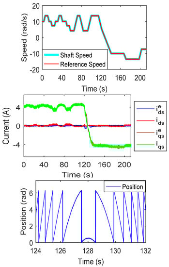
Figure 11.
Experimental results for the forward and reverse motoring operations.
6.2. Forward and Reverse Motoring Operations in a Ramp Speed Command
Figure 12 shows the experimental results for the ramp speed command. The speed command changed between 15 and −15 rad/s in a ramp form. The machine was loaded with a DC generator-type load. The machine was started from a standstill position to 15 rad/s in a ramp form. The drive performance confirmed the ramp speed change with zero crossing also.
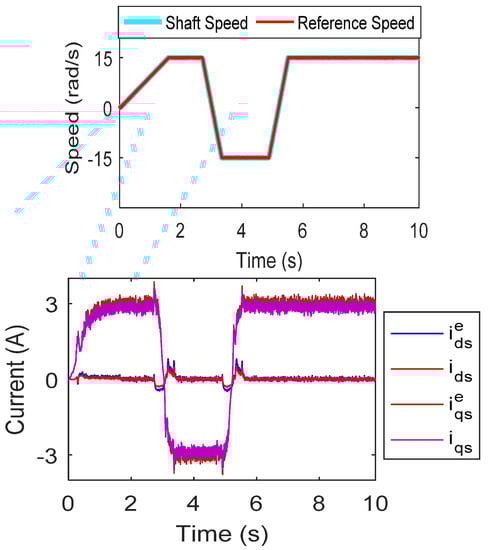
Figure 12.
Experimental results for the forward and reverse motoring with a ramp speed command.
6.3. Drive Operation for the Step Speed Command
Figure 13 shows the experimental results for the step speed change. The machine was loaded with a DC generator-type load. The speed command was altered up to ±10 rad/s in a step form. The drive was verified for the step command, and the results confirmed the performance of the presented algorithm.
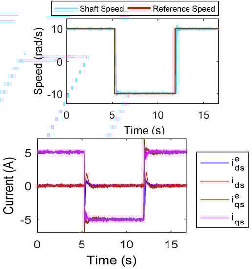
Figure 13.
Experimental results for the step speed command.
6.4. Drive Operation with Online Rotor Resistance Estimation and Compensation
The dive performance was verified for the variation, with online estimation and compensation. Figure 14 shows the actual shaft speed and reference speed command, which was maintained at 5 rad/s. The machine was loaded with a constant load (DC generator load). The was estimated using [34] and compensated to the current estimation technique. The drive performance confirmed the current sensorless algorithm under stator resistance variation.
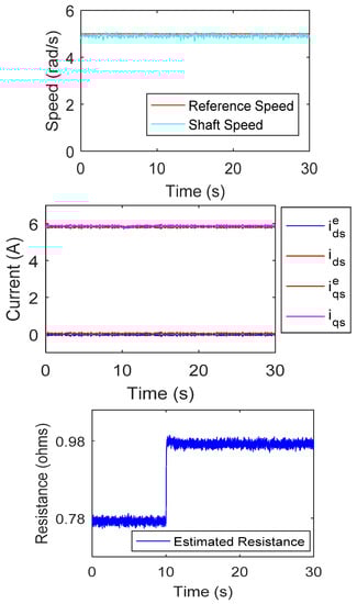
Figure 14.
Experimental results for the online stator-resistance estimation and compensation.
6.5. Drive Operation for the High-Speed Command
Figure 15 shows the experimental results for the high-speed reference command. The machine was connected with a DC generator-type load (i.e., -type load). The machine was initially at the rest position. The reference speed was changed from 0 to 150 rad/s in a ramp form. At 13 s, the load on the machine was varied by changing the load resistance connected to the DC motor. The estimated and actual currents were plotted on the same scale to show the accuracy of the proposed technique.
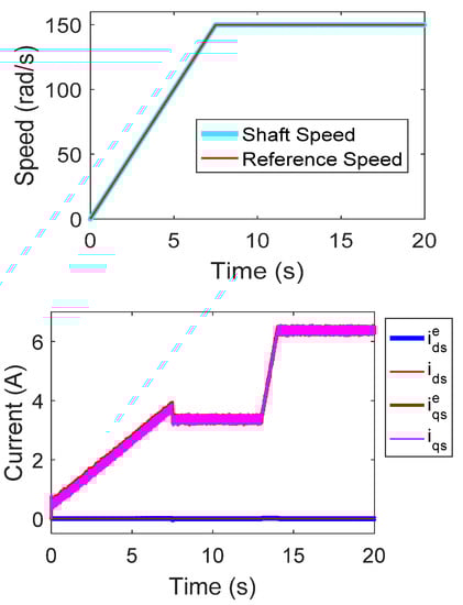
Figure 15.
Experimental results for the high-speed operation.
7. Conclusions
In this paper, a current sensorless PMSM motor with a position/speed sensor was presented. The currents were estimated from the reference voltages. In the d and q axes rotating reference frame, the stator currents were calculated and closed in the loop to perform an all four-quadrant operation. No additional sensors or hardware is required to implement the proposed method, which makes the drive suitable for retrofitting applications. The current sensorless algorithm can be applied to various PMSM motor types. The current estimation technique can be used to monitor the status of the current sensors by implementing them in the existing PMSM drive. A speed sensor is employed to perform the drive operation with the current estimation technique, which reduces the drive cost and complexity. The reliability and immunity to signal noise is reduced by using a single sensor, i.e., speed or position sensor. The proposed drive is independent of the switching states, integrator, and differentiator terms. The sensitivity of the estimated currents is also performed with speed information. The algorithm was tested on the MATLAB/Simulink platform and also verified on a laboratory prototype. Finally, the current sensorless for PMSM was experimentally validated, and the system’s good performance at a variety of speeds and loading circumstances was confirmed.
Author Contributions
Conceptualization, S.S.B. and V.V.; methodology, S.S.B. and V.V.; validation, S.S.B., V.V. and M.T.; formal analysis, S.S.B., V.V. and M.T.; investigation, S.S.B., V.V. and M.T.; resources, V.V.; writing—original draft preparation, S.S.B. and V.V.; writing—review and editing, M.T., S.U. and L.M.-P.; supervision, V.V.; project administration, S.U.; funding acquisition, S.U. and L.M.-P.; All authors have read and agreed to the published version of the manuscript.
Funding
This research was funded by Princess Nourah bint Abdulrahman University Researchers Supporting Project Number (PNURSP2022R79), Princess Nourah bint Abdulrahman University, Riyadh, Saudi Arabia.
Data Availability Statement
Not applicable.
Acknowledgments
Princess Nourah bint Abdulrahman University Researchers Supporting Project Number (PNURSP2022R79), Princess Nourah bint Abdulrahman University, Riyadh, Saudi Arabia.
Conflicts of Interest
The authors declare no conflict of interest.
References
- Krishnan, R. Permanent Magnet Synchronous and Brushless DC Motor Drives; CRC Press/Taylor & Francis: Boca Raton, FL, USA, 2017. [Google Scholar]
- Bose, B.K. Modern Power Electronics and AC Drives; Prentice Hall PTR: Hoboken, NJ, USA, 2002. [Google Scholar]
- Chung, D.W.; Sul, S.K. Analysis and compensation of current measurement error in vector-controlled AC motor drives. IEEE Trans. Ind. Appl. 1998, 34, 340–345. [Google Scholar] [CrossRef]
- Xu, Y.; Yan, H.; Zou, J.; Wang, B.; Li, Y. Zero voltage vector sampling method for PMSM three-phase current reconstruction using single current sensor. IEEE Trans. Power Electron. 2017, 32, 3797–3807. [Google Scholar] [CrossRef]
- Wang, W.; Yan, H.; Xu, Y.; Zou, J.; Zhang, X.; Zhao, W. New three-phase current reconstruction for PMSM drive with hybrid space vector pulse width modulation technique. IEEE Trans. Power Electron. 2021, 36, 662–673. [Google Scholar] [CrossRef]
- Cho, Y.; Labella, T.; Lai, J.S. A three-phase current reconstruction strategy with online current offset compensation using a single current sensor. IEEE Trans. Ind. Electron. 2012, 59, 2924–2933. [Google Scholar] [CrossRef]
- Kim, H.; Jahns, T.M. Current control for AC motor drives using a single DC-link current sensor and measurement voltage vectors. IEEE Trans. Ind. Appl. 2006, 42, 1539–1547. [Google Scholar] [CrossRef]
- Hafez, B.; Abdel-Khalik, A.S.; Massoud, A.M.; Ahmed, S.; Lorenz, R.D. Single-sensor-based three-phase permanent-magnet synchronous motor drive system with luenberger observers for motor line current reconstruction. IEEE Trans. Ind. Appl. 2014, 50, 2602–2613. [Google Scholar] [CrossRef]
- Yan, H.; Wang, W.; Xu, Y.; Jibin, Z. Position sensorless control for PMSM drives with single current sensor. IEEE Trans. Ind. Electron. 2022, 70, 1. [Google Scholar] [CrossRef]
- Ha, J.I. Current prediction in vector-controlled PWM inverters using single DC-link current sensor. IEEE Trans. Ind. Electron. 2010, 57, 716–726. [Google Scholar]
- Saritha, B.; Janakiraman, P.A. Sinusoidal three-phase current reconstruction and control using a DC-link current sensor and a curve-fittins observer. IEEE Trans. Ind. Electron. 2007, 54, 2657–2664. [Google Scholar] [CrossRef]
- Tang, Q.; Shen, A.; Li, W.; Luo, P.; Chen, M.; He, X. Multiple-positions-coupled sampling method for PMSM three-phase current reconstruction with a single current sensor. IEEE Trans. Power Electron. 2020, 35, 699–708. [Google Scholar] [CrossRef]
- Sun, K.; Wei, Q.; Huang, L.; Matsuse, K. An overmodulation method for PWM-inverter-Fed IPMSM drive with single current sensor. IEEE Trans. Ind. Electron. 2010, 57, 3395–3404. [Google Scholar] [CrossRef]
- Zhao, J.; Nalakath, S.; Emadi, A. A high frequency injection technique with modified current reconstruction for low-speed sensorless control of ipmsms with a single dc-link current sensor. IEEE Access 2019, 7, 136137–136147. [Google Scholar] [CrossRef]
- Lai, Y.S.; Lin, Y.K.; Chen, C.W. New hybrid pulsewidth modulation technique to reduce current distortion and extend current reconstruction range for a three-phase inverter using only DC-link sensor. IEEE Trans. Power Electron. 2013, 28, 1331–1337. [Google Scholar] [CrossRef]
- Gu, Y.; Ni, F.; Yang, D.; Liu, H. Switching-State phase shift method for three-phase-current reconstruction with a single DC-Link current sensor. IEEE Trans. Ind. Electron. 2011, 58, 5186–5194. [Google Scholar]
- Lee, W.C.; Hyun, D.S.; Lee, T.K. A novel control method for three-phase PWM rectifiers using a single current sensor. IEEE Trans. Power Electron. 2000, 15, 861–870. [Google Scholar]
- Zhu, L.; Chen, F.; Li, B.; Li, C.; Wang, G.; Wang, S.; Zhang, G.; Xu, D. Phase Current reconstruction error suppression method for single DC-Link shunt PMSM drives at low-speed region. IEEE Trans. Power Electron. 2021, 37, 7067–7081. [Google Scholar] [CrossRef]
- Green, T.C.; Williams, B.W. Derivation of motor line-current waveforms from the DC-Link current of an inverter. IEE Proc. B Electr. Power Appl. 1989, 136, 196–204. [Google Scholar] [CrossRef]
- Boys, J.T. Novel current sensor for PWM AC drives. IEE Proc. B Electr. Power Appl. 1988, 135, 27–32. [Google Scholar] [CrossRef]
- Singh, B.; Goyal, D. Improved DSVM-DTC Based Current Sensorless Permanent Magnet Synchronous Motor Drive. In Proceedings of the 2007 7th International Conference on Power Electronics and Drive Systems, Bangkok, Thailan, 27–30 November 2007; pp. 1354–1360. [Google Scholar]
- Kim, S. Proportional-type performance recovery current tracking control algorithm for PMSM. IET Electr. Power Appl. 2018, 12, 332–338. [Google Scholar] [CrossRef]
- Ha, J.I. Voltage injection method for three-phase current reconstruction in PWM inverters using a single sensor. IEEE Trans. Power Electron. 2009, 24, 767–775. [Google Scholar]
- Montanari, M.; Peresada, S.; Rossi, C.; Tilli, A. Current sensorless position–flux tracking controller for induction motor drives. Mechatronics 2007, 17, 15–30. [Google Scholar] [CrossRef]
- Morimoto, S.; Sanada, M.; Takeda, Y. High-performance current-sensorless drive for PMSM and SynRM with only low-resolution position sensor. IEEE Trans. Ind. Appl. 2003, 39, 792–801. [Google Scholar] [CrossRef]
- Matsuo, T.; Lipo, T.A. Current Sensorless Field Oriented Control of Synchronous Reluctance Motor. In Proceedings of the Conference Record-IAS Annual Meeting, IEEE Industry Applications Society, Toronto, ON, Canada, 2–8 October 1993; IEEE: Piscataway, NJ, USA, 1993; pp. 672–678. [Google Scholar]
- Consoli, A.; Scarcella, G.; Testa, A. Speed and Current Sensorless Field Oriented Induction Motor Drive Operating at Low Stator Frequencies. In Proceedings of the Conference Record-IAS Annual Meeting, IEEE Industry Applications Society, Pittsburgh, PA, USA, 13–18 October 2002; pp. 1679–1686. [Google Scholar]
- Chang, S.C.; Yeh, S.N. Current sensorless field-oriented control of induction motors. IEE Proc. Electr. Power Appl. 1996, 143, 492–500. [Google Scholar] [CrossRef]
- Ohishi, K.; Yoshida, K. Current Sensor-Less Speed Servo System of PM Motor Based on Self-Tuning Current Simulator. In Proceedings of the IEMDC 2003-IEEE International Electric Machines and Drives Conference, Madison, WI, USA, 1–4 June 2003; Institute of Electrical and Electronics Engineers Inc.: Piscataway, NJ, USA, 2003; pp. 1895–1900. [Google Scholar]
- Morimoto, S.; Sanada, M.; Takeda, Y. Optimum efficiency operation of synchronous reluctance motor without current sensor. IEE Conf. Publ. 2000, 506–511. [Google Scholar]
- Morimoto, S.; Kinoshita, K.; Takeda, Y. A current sensorless drive system of a synchronous motor with a low-resolution position sensor. Electr. Eng. Jpn. (Engl. Transl. Denki Gakkai Ronbunshi) 2002, 141, 34–43. [Google Scholar] [CrossRef]
- Teng, Q.; Cui, H.; Duan, J.; Zhu, J.; Guo, Y.; Lei, G. Extended state observer-based vector control for PMSM drive system with single phase current sensor. In Proceedings of the 2017 20th International Conference on Electrical Machines and Systems, ICEMS, Sydney, NSW, Australia, 11–17 August 2017; Institute of Electrical and Electronics Engineers Inc.: Piscataway, NJ, USA, 2017. [Google Scholar]
- Bolognani, S.; Oboe, R.; Zigliotto, M. Sensorless full-digital pmsm drive with ekf estimation of speed and rotor position. IEEE Trans. Ind. Electron. 1999, 46, 184–191. [Google Scholar] [CrossRef]
- Badini, S.S.; Verma, V. A new stator resistance estimation technique for vector-controlled PMSM drive. IEEE Trans. Ind. Appl. 2020, 56, 6536–6545. [Google Scholar] [CrossRef]
Publisher’s Note: MDPI stays neutral with regard to jurisdictional claims in published maps and institutional affiliations. |
© 2022 by the authors. Licensee MDPI, Basel, Switzerland. This article is an open access article distributed under the terms and conditions of the Creative Commons Attribution (CC BY) license (https://creativecommons.org/licenses/by/4.0/).