Article

Stress Analysis of the Radius and Ulna in Tennis at Different Flexion Angles of the Elbow

1
Department of Physical Education, Northwest A&F University, Xi’an 712100, China
2
School of Civil Engineering and Architecture, Xi’an University of Technology, Xi’an 710048, China
*
Author to whom correspondence should be addressed.
Mathematics 2023, 11(16), 3524; https://doi.org/10.3390/math11163524
Submission received: 26 July 2023 / Revised: 11 August 2023 / Accepted: 12 August 2023 / Published: 15 August 2023

Abstract

:
In this paper, based on the finite element method, the stresses of the radius and ulna are analyzed at different flexion angles of the elbow when playing tennis. The finite element model is presented for the elbow position with flexion angles of 0°, 25°, 60°, and 80° according to the normal human arm bone. In this model, the whole arm with metacarpals, radius, ulna, humerus and scapula is considered. The calculation is simplified by setting the scapula and metacarpals as rigid bodies and using Tie binding constraints between the humerus and the radius and ulna. This model is discretized using the 10-node second-order tetrahedral element (C3D10). This model contains 109,765 nodes and 68,075 elements. The hitting forces applied to the metacarpal bone are 100 N and 300 N, respectively. The numerical results show that the highest principal stresses are at the points of 1/4 of the radius, the elbow joint, and the points of 1/10 of the ulna. The results of the maximum principal stress show that the external pressures are more pronounced as the elbow flexion angle increases and that the magnitude of the hitting force does not affect the principal stress distribution pattern. Elbow injuries to the radius can be reduced by using a stroke with less elbow flexion, and it is advisable to wear a reinforced arm cuff on the dorsal 1/4 of the hand, a radial/dorsal hand wrist, and an elbow guard to prevent radial ulnar injuries.
MSC:
74L15

1. Introduction

Tennis is a high-intensity sport that increases the mechanical load, resulting in increased bone density and life-long benefits [1,2,3,4,5]. In addition, tennis was included in the Olympic Games in 1998 and became a popular sport for all, with tens of millions of people participating worldwide [6,7]. As the number of people playing tennis increases, the proportion of injuries and illnesses among those participating in the sport gradually rises. Studies have shown that men and women are 45.56% and 42.49% more likely to be injured in tennis, respectively, with up to a quarter of these injuries occurring in the upper limbs [8]. In Peter Kaiser’s statistics on patients treated for tennis injuries, 72% of the sample with fracture injuries happened in the upper body [9]. In tennis, upper limb injuries are chronic [10]. Among chronic upper limb injuries, epicondylitis of the humerus (also known as tennis elbow) is a tendinopathy of the radial, short extensor carpi radials caused by overuse. It is the primary injury in tennis [11]. Thus, it is necessary to have a reasonable and correct understanding of the causes of injuries and illnesses [12,13].
Momentum and impact are an integral part of the game of tennis. Gordon and Dapena measured the joint movements of nine male tennis players in the 3D film. They found that elbow abduction and wrist flexion had the most significant effect on the service in speed and angle, with the elbow and wrist being the most injury-prone positions in the sport [14]. Wu et al. developed a mathematical model based on three-dimensional coordinates to estimate tennis contact duration and peak impact force, comparing the racquet impact intensity of the two hitting techniques and showing that a longer backswing during the preparation phase reduces the final peak impact force and can reduce the risk of upper limb injury [15]. Bahamonde and Rafael used three-dimensional photography and direct linear transformation to establish the right-hand coordinates of tennis ball motion, with most of the angular momentum (75.1%) concentrated at the racket arm during close collisions, with the angular momentum mainly focused at the racket segment (35.9%) and the radial, ulnar component (25.7%) [16].
A few studies on radial ulnar injuries have been published. Ireland et al. measured the strength parameters and muscle size of the radial-ulnar bone in tennis players by quantitative peripheral calculations, i.e., tomography, and concluded that the maximum stress that determines bone strength in tennis does not lie in the muscles and bones are caused by torsional loads [17,18]. Bollen et al. studied stress fractures through case studies and found that stress fractures in tennis are associated with backhand hitting and excessive internal rotation and occur at 1/3th of the ulnar [19]. Jones discussed the mechanism of injury and treatment of stress fractures of the radius and ulna. He found that stress fractures of the distal growth plate of the radius are common and usually manifest as widening and irregularity of the distal epiphysis and that ulnar fractures occur at the 1/3rd because this is the region with the thinnest cortex and smallest cross-sectional region compared to the proximal and distal ends of the bone. That impact is essential in causing differential stress fractures in the weakest region of the ulna [20,21]. Anderson studied stress fracture injuries by diagnostic implications, and macroscopic stress fractures develop further from micro-injuries caused by imbalances in bone production and resorption. Ulnar fractures are caused by forces from forearm loading and weaker regions, usually occurring in the proximal and distal two-thirds of the ulna. Radial fractures may be present bilaterally with additional torsional shear stress. The fracture usually occurs at the distal end of the radius [22].
Tennis injuries are related to various factors, such as stroke action and racket grip [23]. Biomechanics can be used to effectively analyze the forces and injuries to bones in sports [24], with the finite element method (FEM) being an effective tool for skeletal biomechanical analysis [25]. Gíslason et al. validated a finite element model of the wrist bone, showing that it is feasible to assume that the bone is isotropic, that the elastic modulus of the cortical bone is 18 GPa [26], that the Poisson’s ratio is 0.3, and that a tetrahedral four-node element is the appropriate model element type [27]. Zhang et al. thought that bone was a poroelastic material [28,29,30]. After combining the porous medium theory to model fractured bone with the addition of a fixator, the effects of axial loading and fracture gap size on bone healing were investigated. The results showed that the fracture gap size of the bone was the most influential in mesenchymal stem cell (MSC) differentiation and that the periosteum was the key region for early bone scab. In finite element modeling of the human wrist, Gíslason and Nash believed that the properties of the skeleton depend on the strain rate and that for quasi-static analysis, Young’s modulus of cortical bone should be between 17.1 and 19.1 GPa, with a Poisson’s ratio of 0.25 and a unit type of tetrahedral element [31]. Lewis et al. analyzed fracture fixation by finite element modeling. Regarding failure criteria, the prediction of skeletal failure is usually analyzed using the minimum principal strain as the primary indicator of fracture fixation [32]. Imai et al. used a non-linear finite element model to predict the vertebral fracture site and also chose the minimum principal strain criterion and concluded that the bone fails at a minimum principal strain of less than 10,000 με [33]. Schileo et al. built a finite element model of the humerus based on CT data. They compared the measured results of the three failure criteria of Von Mises, maximum principal stress, and maximum principal strain [34]. While the maximum principal strain failure criterion is the predominant criterion for skeletal failure in the study, Ota’s simulation of the femoral fracture using the finite element method found that the maximum stress and strain location is where the bone is most vulnerable. There was no significant difference in the final failure location between the maximum principal stress criterion and the maximum principal strain criterion [35].
Based on the above background, this paper presents a mechanical analysis of the radial and ulnar at different flexion angles of the elbow when hitting the ball in tennis. The selected motions are straight-arm forehand catching, serving, forehand baseline hitting, and backhand hitting. A finite element model is established according to the four movements. Different hitting forces are set to act on the palm, the location of the maximum principal stress distribution, the cross-sectional stress distribution at the point of maximum principal stress, and the axial distribution are used to find the causes of injury in tennis are identified through the location of the maximum principal stress distribution, the cross-sectional stress distribution and the axial distribution.

2. Finite Element Method for Human Skeletal Analysis

The basic equations of three-dimensional (3D) elasticity used are considered in this paper [36,37,38].
In a domain Ω, the equilibrium differential equation is
σ + f = 0
where is a differential operator,
= [ x 0 0 y 0 z 0 y 0 x z 0 0 0 z 0 y x ]  
σ is the stress vector,
σ = [ σ x σ y σ z τ x y τ y z τ z x ] T
f is the body force vector,
f = [ f x f y f z ] T
The geometric equation is
ε = L u
where ε is the strain vector, u is the displacement vector,
ε = [ ε x ε y ε z γ x y γ y z γ z x ] T
L = T  
u = [ u v w ] T
The constitutive equation is
σ = D ε
where
D = E ( 1 μ ) ( 1 + μ ) ( 1 2 μ ) [ 1 μ 1 μ μ 1 μ 0 0 0 μ 1 μ 1 μ 1 μ 0 0 0 μ 1 μ μ 1 μ 1 0 0 0 0 0 0 1 2 μ 2 ( 1 μ ) 0 0 0 0 0 0 1 2 μ 2 ( 1 μ ) 0 0 0 0 0 0 1 2 μ 2 ( 1 μ ) ]
for three-dimensional problems. Here, E is the elastic modulus, and μ is Poisson’s ratio.
The boundary of the domain V is S, and
S = S σ + S u
where S σ and S u are the boundaries on which the stress and displacement are prescribed, respectively.
The boundary conditions are
n σ = T ¯   ( on   S σ )
u = u ¯   ( on   S u )
where
n = [ n x 0 0 n y 0 n z 0 n y 0 n x n z 0 0 0 n z 0 n y n x ]
T ¯ is the vector of prescribed stress,
T ¯ = [ T ¯ x T ¯ y T ¯ z ]
and u ¯ is the known displacement,
u ¯ = [ u ¯ v ¯ w ¯ ] T
The displacement, stress, and strain functions in a finite element are
u = N u e
ε = B u e
σ = D ε = D B u e = S u e
where ue is the node displacement vector on an element, B is the strain matrix, S is the stress matrix, and N is the shape function matrix of the element.
The generalized total potential energy can be obtained as
Π = e ( u e T Ω e 1 2 B T D B t d Ω u e ) e ( u e T Ω e N T f t d Ω ) e ( u e T S σ e N T T t d S )
where Ke is the element stiffness matrix,
K e = Ω e B T D B t d Ω
P e is the equivalent nodal load vector,
P e = P f e + P S e
and
P f e = S σ e N T f t d Ω
P S e = S σ e N T T t d S
Substituting Equations (21)–(24) into Equation (20) yields
Π = u T 1 2 e ( G T K e G ) u u T e ( G T P e )
where K is the total stiffness matrix,
K = e G T K e G
and P is the total nodal load vector,
P = e G T P e
According to the variational principle, we have
δ Π δ u = 0
Then the final equation of the finite element method can be obtained as
K u = P

3. Finite Element Modeling of Different Elbow Flexion Angles in Tennis

Based on standard human arm bone data, the target geometry model is completed using the software Geomagic Studio and Hypermesh, and a 3D finite element model of the human arm bone can be obtained.
In tennis, the human arm is subjected to impact during the hitting process, and the hitting action leads to different locations of impacted force and, consequently, different locations of susceptibility to injury. The arm comprises five parts: palm, radius, ulna, elbow, and humerus (Figure 1).
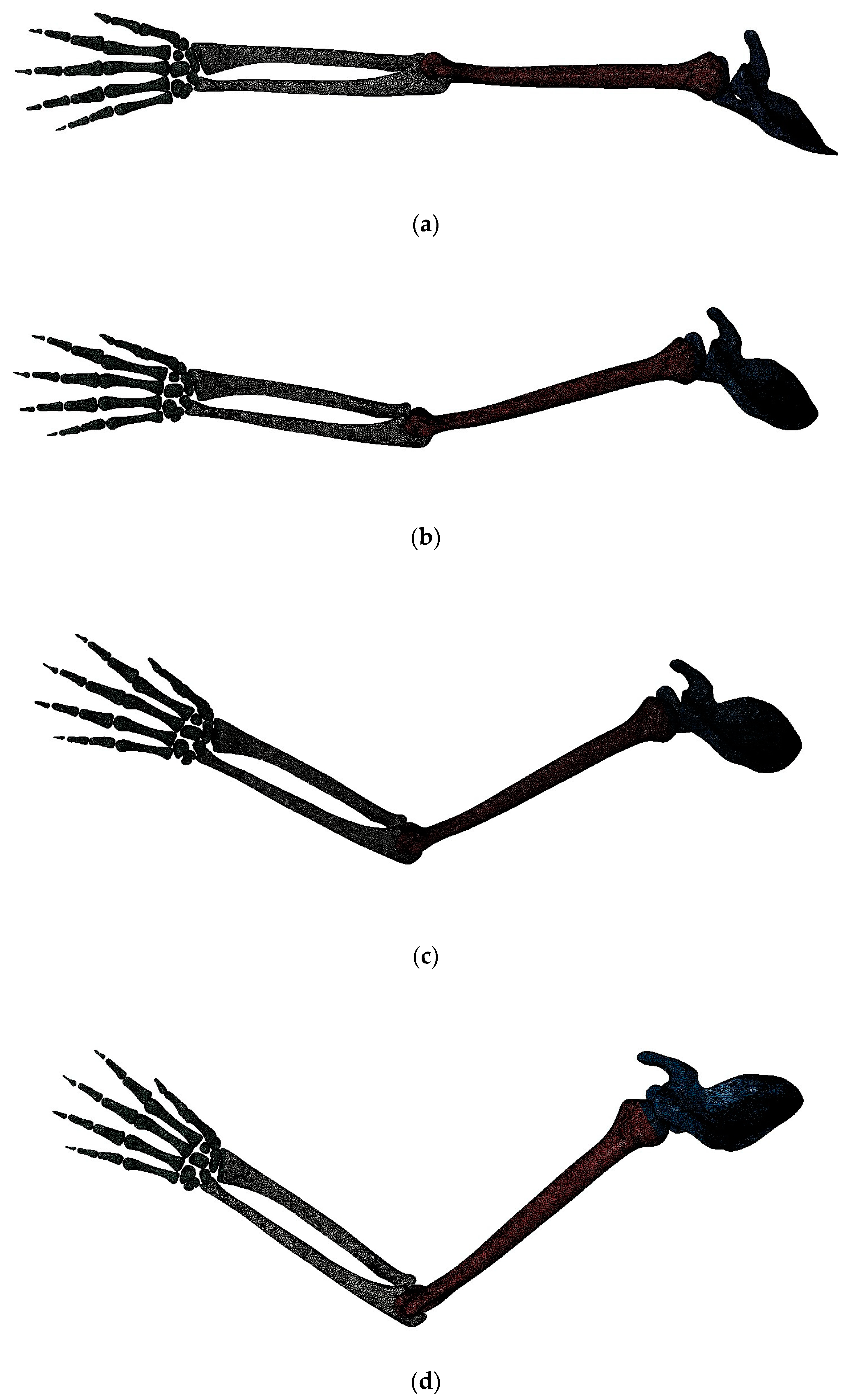
The straight-arm forehand catch, serve, forehand baseline stroke, and backhand hitting motions are established for four distinct action states in the chosen tennis move. These states correspond to elbow flexion angles of 0°, 25°, 60°, and 80°, as shown in Figure 2.
From a biomechanical point of view, bone tissue is a biphasic composite, with one phase being inorganic and the other being collagen and an amorphous matrix. In this paper, bone is considered a uniformly distributed and isotropic linear elastic continuum for finite element analysis, with a bone elastic modulus of 18 GPa and a Poisson’s ratio of 0.3 [39].
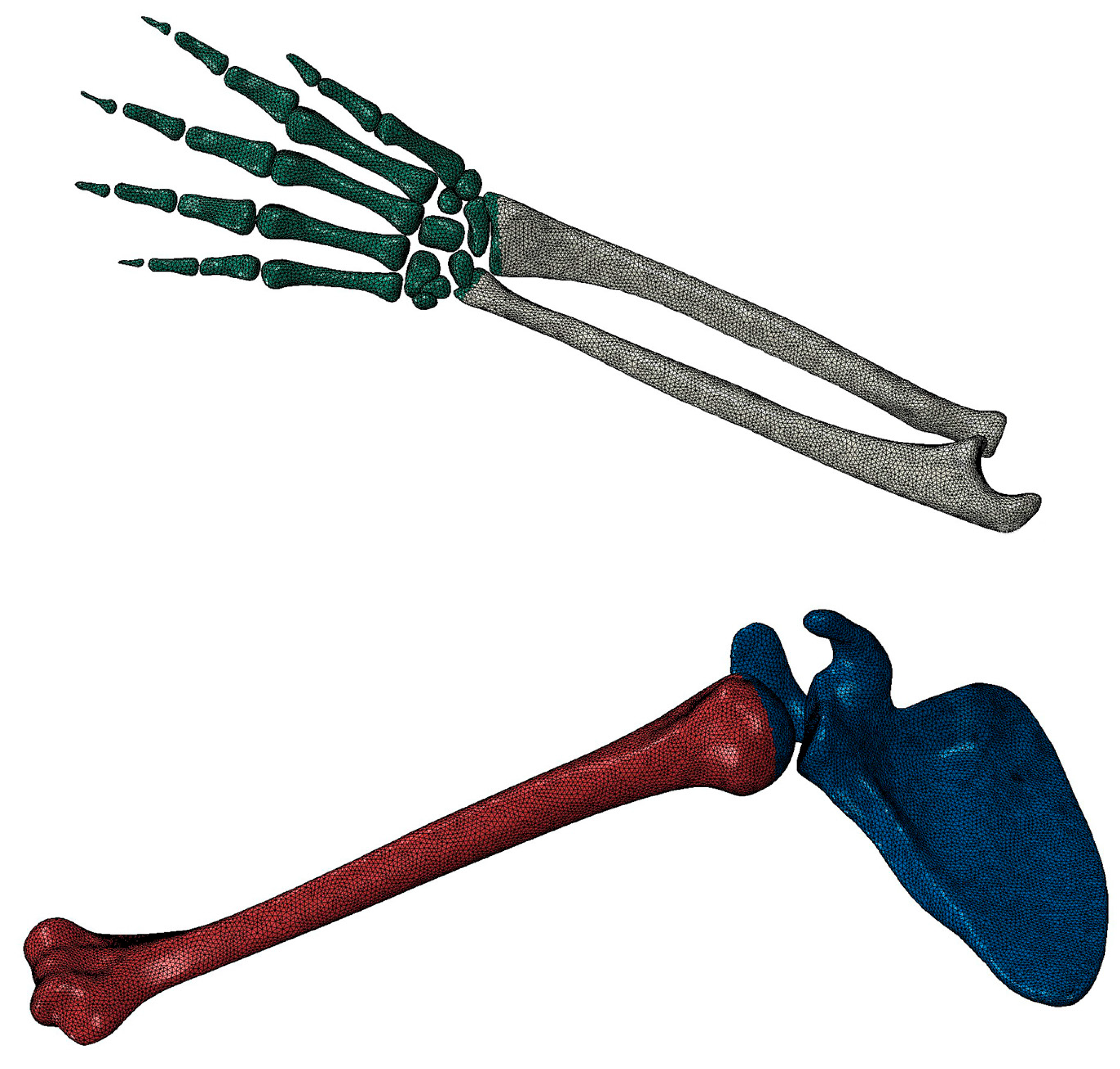
This model is discretized using the 10-node second-order tetrahedral element (C3D10). This model includes the palm bone, radius, ulna, humerus, and scapula, where the radius/ulnar elements/nodes are 32,355/52,276 and 35,720/57,487, respectively. The finite element meshing is shown in Figure 3. This model mesh has three displacements per node (three degrees of freedom).
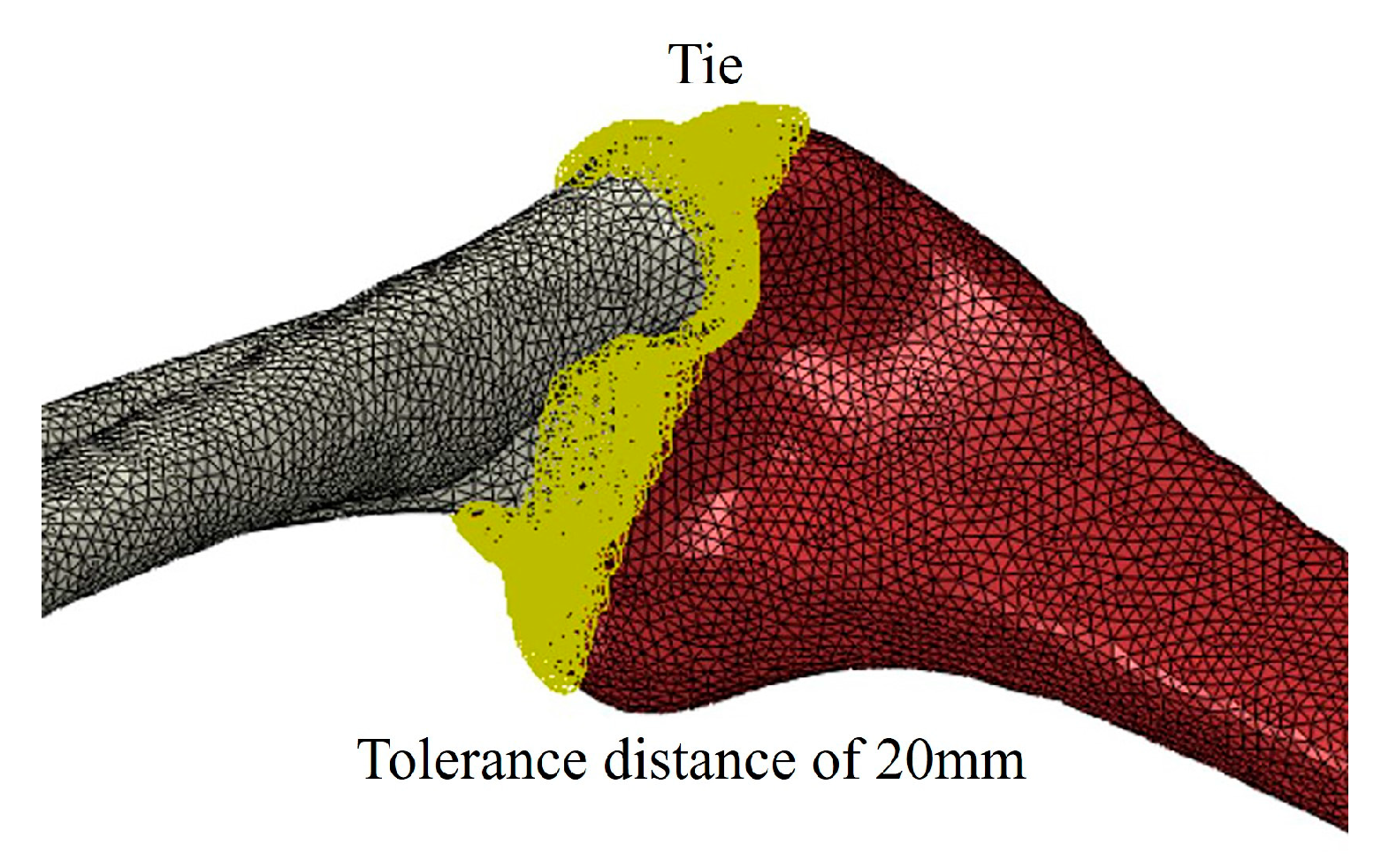
The scapula and metacarpal are set as rigid bodies, fixed in the normal human anatomical position. At the proximal part of the scapula, the translational displacements in the x, y, and z directions are constrained; at the metacarpal bone, only the displacements in the direction of the applied concentrated force are unrestricted, while the translational and rotational displacements in the other directions are restricted. The elbow joint connects the humerus, radius, and ulna, where the human body can flexibly achieve both flexion and internal and external rotation. The forces at the elbow joint are complex, so to simplify the calculation, a Tie-binding constraint is set between the humerus, radius, and ulna at the elbow joint, with a specified tolerance distance of 20 mm so that the contact surfaces of the humerus and the radius-ulna are firmly bonded together and do not separate during the force (Figure 4).
The hitting force is calculated as
F = m a = m v 2 2 s
where s is the acceleration distance/m, m is the mass of the tennis ball/kg, and v is the speed of the tennis ball after acceleration/m·s−1.
After observing the world-class tennis open tournament and reviewing relevant references [40,41,42], it can be found that the hitting speed of an average-level player is about 110 km/h, and the hitting rate of a top-level player can be about 190 km/h. The mass of the tennis ball is about 0.06 kg, the speed of the tennis ball is accelerated from 0 m/s to 30.6 m/s (110 km/h), and the distance of the accelerated movement is 0.3 m, assuming that the acceleration magnitude is constant during the movement, as calculated in the Equation (30), F is 93.4 N; similarly, when accelerating to 55.6 m/s (200 km/h), F is 308.6 N. Hence, the forces of 100 N and 300 N are applied vertically to the palm to simulate the interaction between the handle of the tennis racket and the palm during the movement of a tennis ball.

4. Numerical Results and Analysis

The calculation results mainly include the maximum principal stress point, the cross-sectional stress distribution at the maximum principal stress point, and the axial principal stress distribution, and the radius and ulna are analyzed and discussed, respectively, according to the above results.
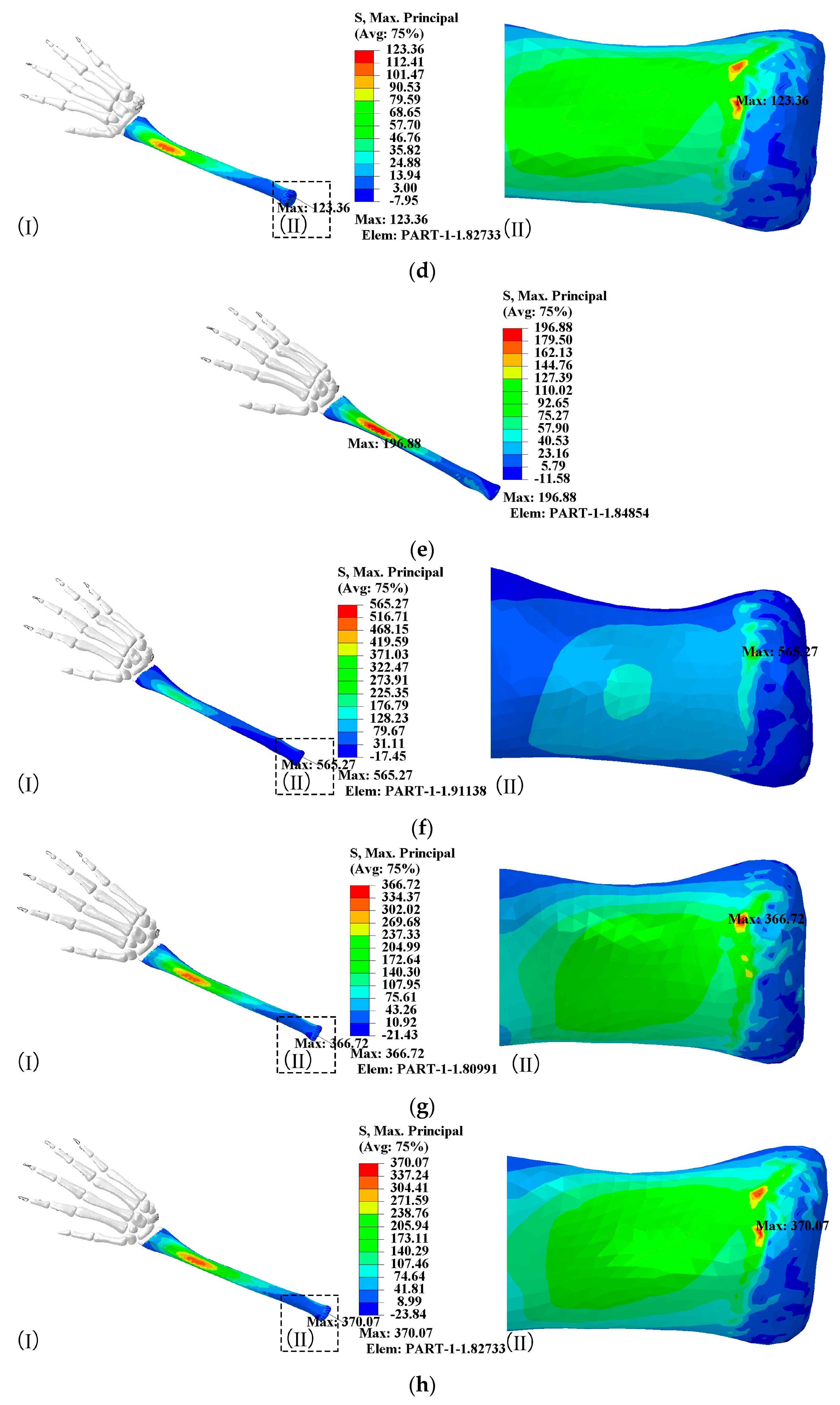
The numerical results of the maximum principal stress of the radius are shown in Figure 4.
It is evident from Figure 5a that the most concentrated stress region is located on the dorsal side of the hand for compressive stress. So, when flexing the elbow at 0°, it is more probable for the radius to sustain a fracture injury on the compression side rather than the tension side. The distribution of the principal stress is elliptical and gradually decreases outwards. The site is concentrated at 0-2/3, and the principal stress transfer is along the angle of internal rotation and axially along the end of the elbow joint. When striking with a flexion angle of 25–80°, the elbow joint on the dorsal side of the radial hand experiences the highest principal stress value (as shown in Figure 5b–d). As the flexion angle increased, the concentration of principal stress also increased. At 25° of flexion, there was only one point of principal stress concentration. However, a higher concentration appeared at 60° of flexion, and at 80 degrees of flexion, there are higher values and more noticeable regions of maximum principal stress concentrations. In elbow flexion at 25–80°, the principal stress maximum is at the elbow joint, and after multiple impacts over a long period, the bones do not have enough bearing capacity, and the muscles compensate to meet the bearing capacity of the elbow, which may be the reason for the formation of tennis elbow. As the angle of elbow flexion increases, the maximum value of the principal stress also increases gradually from 65.63 MPa to 123.36 MPa. This means an increase in the elbow flexion angle increases the maximum principal stress of the radius.
Compared to hitting force at 100 N, 300 N shows essentially the same maximum principal stress distribution, with the principal stress becoming about three times larger than before, so the value of the force does not change the principal stress distribution (Figure 5e–h).
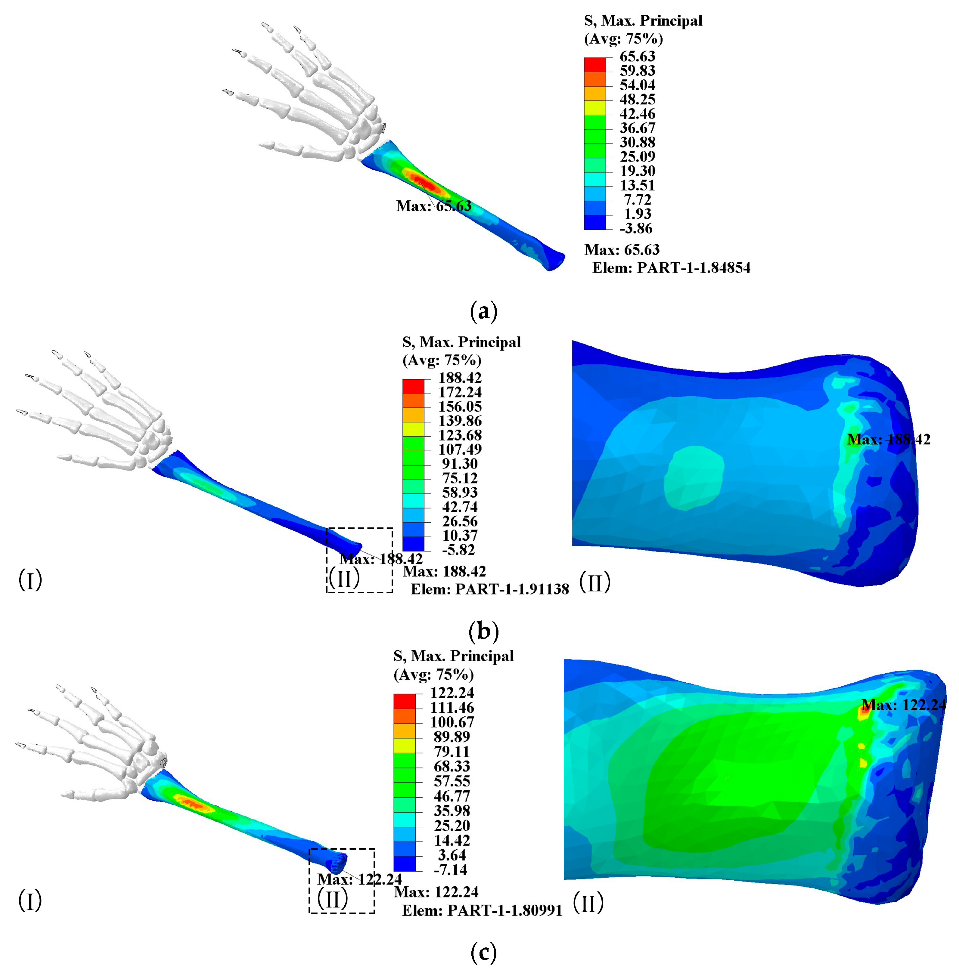
The cross-sectional stress distribution at the maximum principal stress of the radius is shown in Figure 6.
Figure 6a reveals that the maximum principal stress cross-section for the 0° flexion action is on the 1/4 side of the radius, with a stratified distribution of principal stress, mainly compressed on the dorsal side of the radial hand, with each layer graded clearly. The maximum principal stress in the tensioned part of the radius remained unchanged. The compressed region was evenly situated about the dorsal line of the hand, and the compressed side bore the majority of the stress. When the elbow flexion is 25°, the radial principal stress is directed towards the elbow joint, causing internal rotation (Figure 6b). The medial side of the joint experiences the highest level of principal stress and is subject to more points of compressive stress distribution. The lateral side of the elbow is subject to a greater range of tensile but smaller tensile stress values. In the 60° flexion motion (Figure 6c), the medial compressive stress at the radial elbow joint gradually spreads inwards, and in the 80° flexion motion (Figure 6d), the maximum principal stress does not apply further to the tension side. The maximum principal stress at the radial elbow joint in all hitting motions is the serving motion (elbow flexion 25°), with a maximum principal stress value of 188.42 MPa.
In Figure 7, the radial principal stress is focused on approximately one-third of the radius when subjected to a hitting force. Additionally, the distribution of principal stresses is similar between 0° and 25° of elbow flexion near the elbow joint. However, when the elbow flexion is 25°, the principal stress increases slightly. For elbow flexion in the 60–80° range, the distribution of principal stress was similar, and the maximum values substantially increased. The principal stress distribution does not change for 300 N: the larger the flexion angle, the larger the principal stress value.
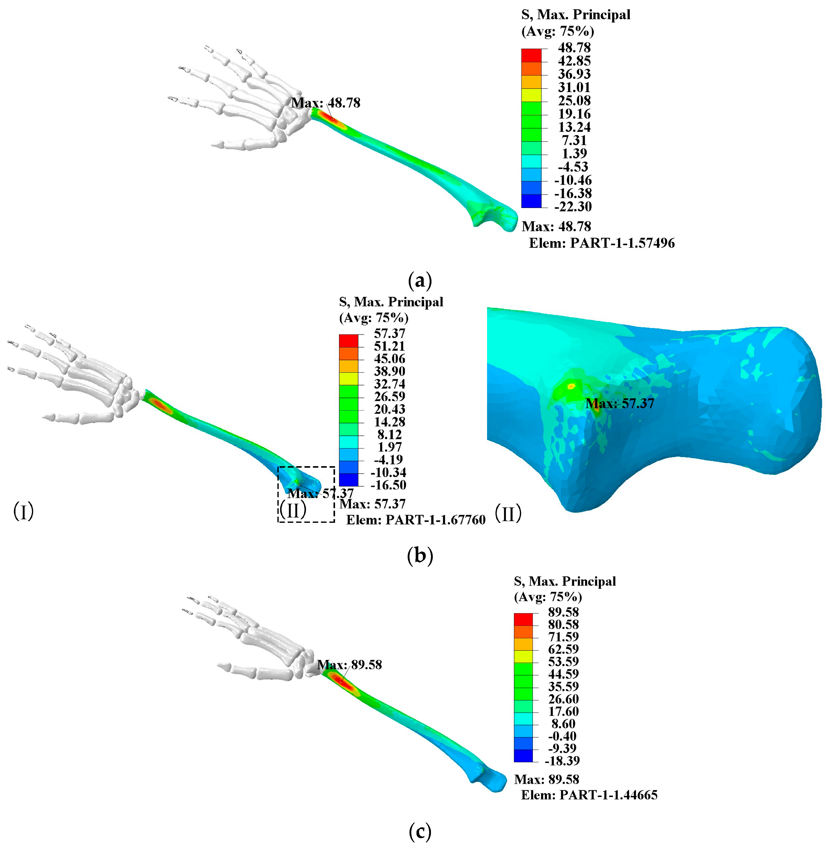
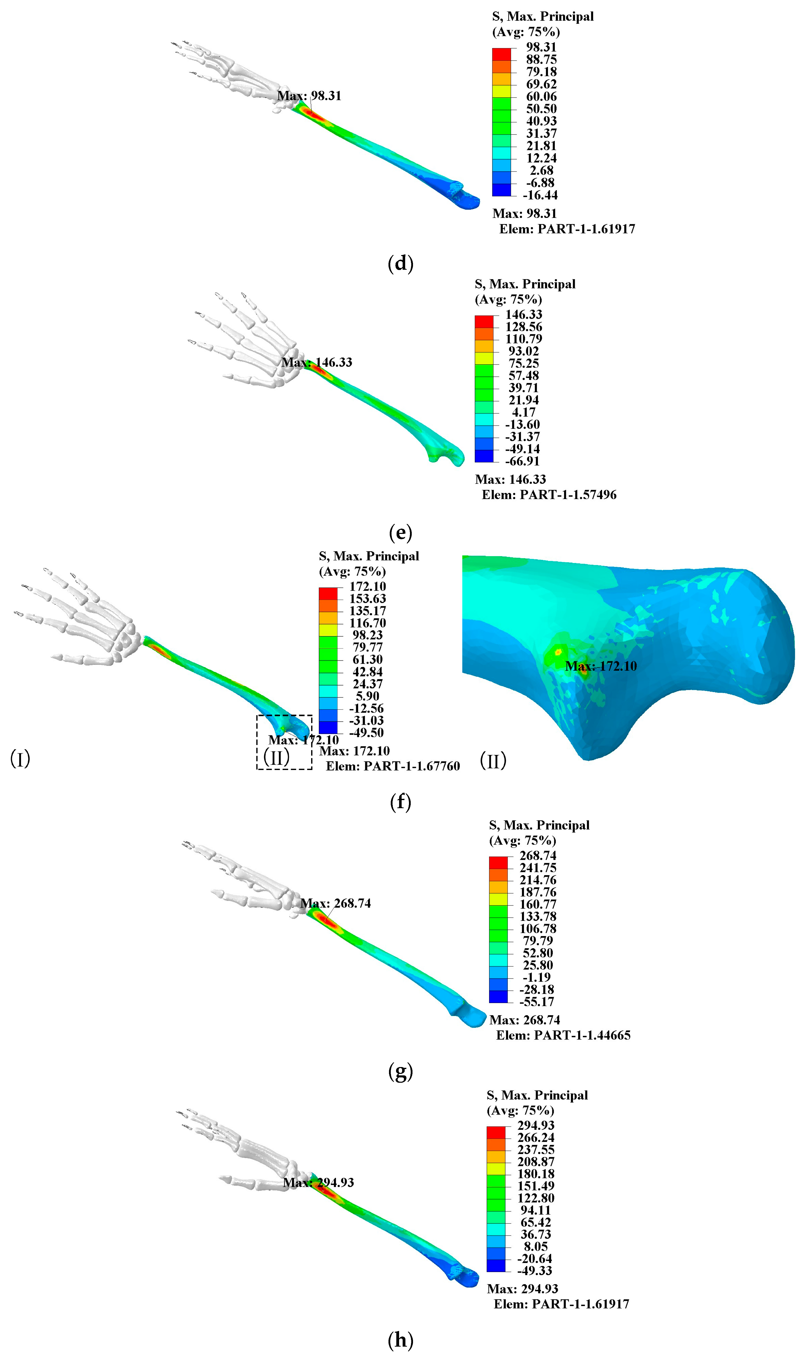
The numerical results of the maximum principal stress of the ulna are shown in Figure 8.
In Figure 8a, the maximum principal stress can be seen on the compressed side of the dorsum of the hand. This stress is concentrated at 1/10th on the proximal ulnar side. The transfer of the principal compressive stress occurs along the palmar side of the hand with a wide range of axial transfer. Additionally, the principal stress is locally rising near the elbow joint and distributed around the ulnar joint. As the elbow flexion angle increases, the principal stress steadily rises from 48.78 MPa to 98.31 MPa. Figure 8b shows that the principal stress concentration distribution region rotates towards the ulnar side. The region of principal stress concentration remains at the ulnar 1/10th, with the highest principal stress located in the elbow joint and with a value of 57.37 MPa. Furthermore, it is noticeable that the maximum principal stress is concentrated at the elbow in the form of a point (Figure 8b-(II)). As the flexion angle from 60°to 80° (Figure 8c,d), the principal stress concentration shifts from the dorsal side of the hand to the ulnar side. However, the location of the maximum principal stress in the axial direction remains unchanged. Comparing Figure 8e–h, the rise in principal stresses is directly linked to the growth in load operating on the hand. Similar to the radius, the distribution of principal stress remained unchanged despite the 300 N hitting force.
The cross-sectional stress distribution at the maximum principal stress of the ulna is shown in Figure 9.
At elbow flexion is 0°, the principal stress in the ulna is distributed in layers, with the region on the tensile side being more significant than the compressive side (Figure 9a). At elbow flexion is 25°, the maximum principal stress is at the elbow joint, where the radial parallel ulna is compressed, and the principal stress is not transmitted medially (Figure 9b). At elbow flexion is 60°, the principal stress on the compressed side surrounds the axial region, and the principal stress on the ulnar side gradually increases. In Figure 9d, the maximum principal stress cross-sectional stress distribution for the 80° flexion action of the elbow is similar to that of 60°, with the maximum principal stress increasing to 98.31 MPa. Changes in striking force and elbow flexion angle during striking increase the principal stress that gradually spreads from the surface to the interior of the bone.
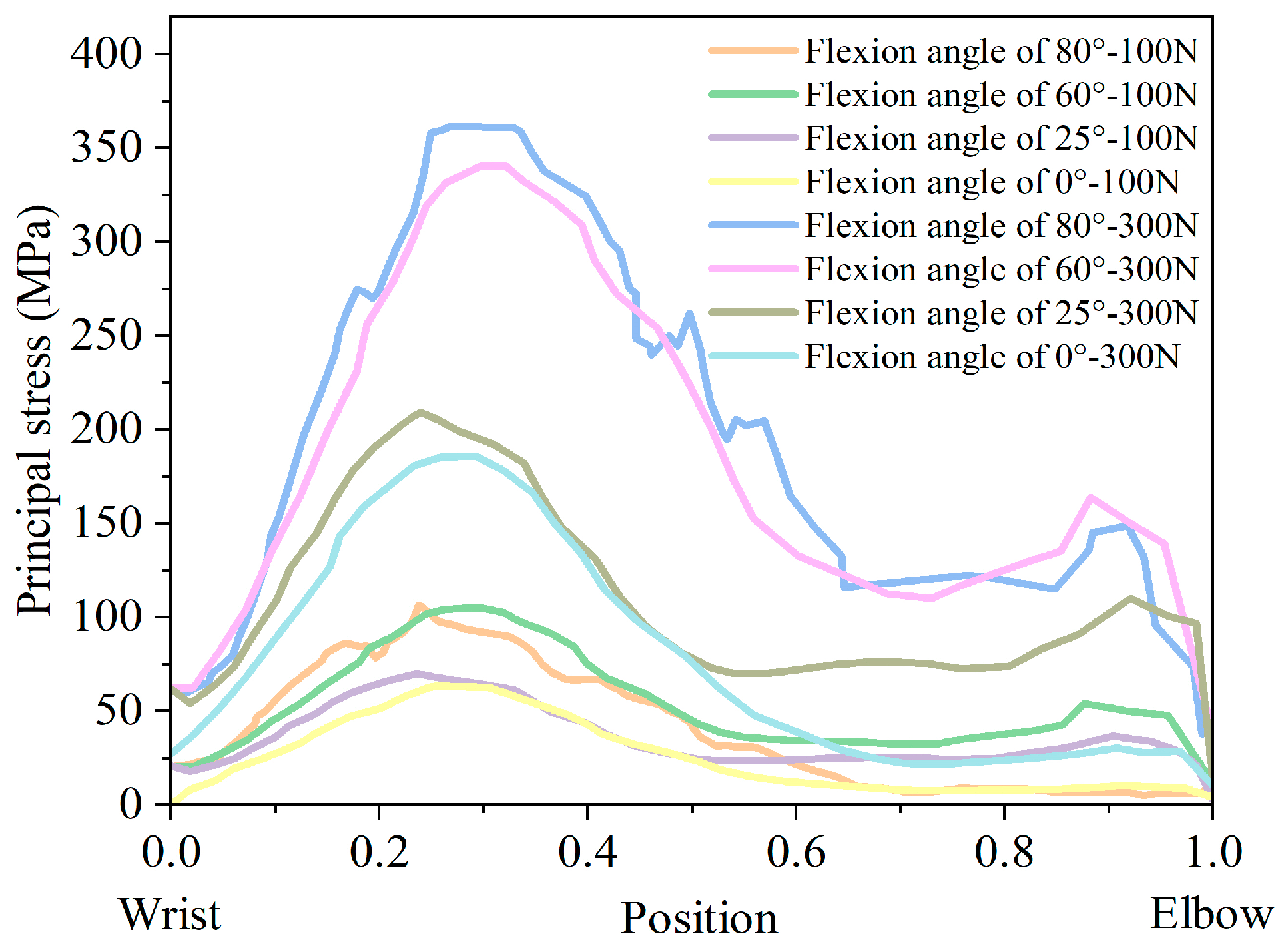
The ulna’s principal stress distribution is from the wrist to the elbow joint, as shown in Figure 10.
The maximum principal stress in the ulna is one-tenth of the wrist, and the values and distribution of the maximum principal stress are similar. Changes in the elbow flexion angle do not affect the orientation of the maximum principal stress on the length of the ulna. In addition, at an elbow flexion angle is 25°, the principal stress value fluctuates at the ulnar 1/2 and near the wrist end. The small cross-sectional area at the proximal wrist end makes it vulnerable to injury.
The conclusions of the numerical simulation analysis are as follows:
  • When the elbow flexion is 0°, the maximum principal stress is generated at about 1/4th of the radius. At the elbow flexion is 25–80° range of elbow flexion, the maximum principal stress acts at the elbow joint as compressive stress;
  • The maximum principal compressive stress is generated at 1/10th of the ulna at 0° and 60–80° elbow flexion. At elbow flexion is 25°, the maximum principal stress is located at the elbow joint on the length of the ulna, with the region of concentration of the principal stress at 1/10th and at the elbow joint;
  • A change in hitting force does not change the principal stress distribution, which increases directly to the hitting force.

5. Conclusions

This paper explores the problem of injuries that occur while hitting the ball at four different elbow flexion angles by using the finite element method. There are some conclusions as follows:
  • The radius is most vulnerable at a quarter of its length, and when the elbow flexion is 25–80°, it is more likely to injury. For better joint protection in the radius and elbow joints, hitting the ball with a straight arm motion is recommended more frequently. Additionally, wearing quarter-position impact-resistant arm sleeves and elbow pads can provide further protection;
  • Injuries to the ulna bone are most likely to occur near the wrist. To minimize the risk of such injuries, it is recommended to wear wrist guards with reinforcements of radial and dorsal hand-side.
  • In recent years, meshless methods have developed rapidly, especially the element-free Galerkin (EFG) method and the corresponding improved methods [43,44,45]. Based on the moving least-squares approximation, the EFG method can obtain solutions with great precision, because the least-squares method in mathematics results in the best approximation [46,47,48]. With the development of bone mechanics, the muscle and skin should be considered when analyzing the stress analysis of the radius and ulna in tennis. Then the large deformation of bone, muscle, and skin will be considered. The meshless method has advantages over the finite element method when analyzing large deformation problems. Then meshless method will be applied to the stress analysis of the radius and ulna in tennis in the future.

Author Contributions

Conceptualization, Y.C. and Q.D.; formal analysis, X.Y. and R.F.; software, X.Y.; methodology, Y.C. and Y.Z.; writing—review and editing, Y.C. and Q.D.; supervision, Y.Z. All authors have read and agreed to the published version of the manuscript.

Funding

The research is supported by the National Natural Science Foundation of China (Grant No. 52078419) and the Scientific Research Fund of Shaanxi physical education and sports bureau Department (Grant No. 2022330).

Data Availability Statement

Not applicable.

Conflicts of Interest

The authors declare no potential conflict of interest regarding the research, authorship, and publication of this article.

References

  1. Warden, S.J.; Galley, M.R.; Hurd, A.L.; Wallace, J.M.; Gallant, M.A.; Richard, J.S.; George, L.A. Elevated mechanical loading when young provides lifelong benefits to cortical bone properties in female rats independent of a surgically induced menopause. Endocrinology 2013, 154, 3178–3187. [Google Scholar] [CrossRef] [PubMed]
  2. Honda, A.; Sogo, N.; Nagasawa, S.; Kato, T.; Umemura, Y. Bones benefits gained by jump training are preserved after detraining in young and adult rats. Am. Physiol. Soc. 2008, 105, 849–853. [Google Scholar] [CrossRef] [PubMed] [Green Version]
  3. Ducher, G.; Prouteau, S.; Courteix, D.; Benhamou, C.-L. Cortical and trabecular bone at the forearm show different adaptation patterns in response to tennis playing—ScienceDirect. J. Clin. Densitom. 2004, 7, 399–405. [Google Scholar] [CrossRef]
  4. Ducher, G.; Tournaire, N.; Meddahi-Pellé, A.; Benhamou, C.-L.; Courteix, D. Short-term and long-term site-specific effects of tennis playing on trabecular and cortical bone at the distal radius. J. Bone Miner. Metab. 2006, 24, 484–490. [Google Scholar] [CrossRef] [PubMed]
  5. Warden, S.J.; Wright, C.; Fuchs, R.K. Bone microarchitecture and strength adaptation to physical activity: A within-subject controlled HRpQCT study. Med. Sci. Sports Exerc. 2021, 53, 1179–1187. [Google Scholar] [CrossRef] [PubMed]
  6. Pluim, B.M.; Staal, J.B.; Windler, G.E.; Jayanthi, N. Tennis injuries: Occurrence, aetiology, and prevention. Br. J. Sports Med. 2006, 40, 415–423. [Google Scholar] [CrossRef] [Green Version]
  7. Abrams, G.D.; Renstrom, P.A.; Safran, M.R. Epidemiology of musculoskeletal injury in the tennis player. Br. J. Sports Med. 2012, 46, 492. [Google Scholar] [CrossRef]
  8. Sallis, R.E.; Jones, K.; Sunshine, S.; Smith, G.; Simon, L. Comparing sports injuries in men and women. J. Sports Med. 2001, 22, 420–423. [Google Scholar] [CrossRef] [Green Version]
  9. Kaiser, P.; Stock, K.; Benedikt, S.; Ellenbecker, T.; Arora, R. Acute tennis injuries in the recreational tennis player. Orthop. J. Sports Med. 2021, 9, 232596712097367. [Google Scholar] [CrossRef]
  10. Chung, K.C.; Lark, M.E. Upper extremity injuries in tennis players: Diagnosis, treatment, and management. Hand Clin. 2017, 33, 175–186. [Google Scholar] [CrossRef] [Green Version]
  11. Mircea, M.; Mereuta, C.; Iordan, D.A. Injuries resulting from practicing performance sports in table tennis and tennis. Ann. Dunarea Jos Univ. Galati 2021, 2, 12–13. [Google Scholar]
  12. Kramer, D.E. Elbow pain and injury in young athletes. J. Pediatr. Orthop. 2010, 30, 7–12. [Google Scholar] [CrossRef] [Green Version]
  13. Patrick, N.C.; Hammert, W.C. Hand and wrist tendinopathies. Clin. Sports Med. 2020, 39, 247–258. [Google Scholar] [CrossRef] [PubMed]
  14. Gordon, B.J.; Dapena, J. Contributions of joint rotations to racquet speed in the tennis serve. J. Sports Sci. 2006, 24, 31–49. [Google Scholar] [CrossRef] [PubMed]
  15. Wu, S.K.; Gross, M.T.; Prentice, W.E.; Yu, B. Comparison of ball-and-racquet impact force between two tennis backhand stroke techniques. J. Orthop. Sports Phys. Ther. 2000, 31, 247–254. [Google Scholar] [CrossRef] [Green Version]
  16. Bahamonde, R.E. Changes in angular momentum during the tennis serve. J. Sports Sci. 2000, 18, 579–592. [Google Scholar] [CrossRef]
  17. Ireland, A.; Degens, H.; Maffulli, N.; Rittweger, J. Tennis service stroke benefits humerus bone: Is torsion the cause? Calcif. Tissue Int. 2015, 97, 193–198. [Google Scholar] [CrossRef] [PubMed]
  18. Ireland, A.; Maden-Wilkinson, T.; Mcphee, J.; Cooke, K.; Narici, M.; Degens, H.; Rittweger, J. Upper limb muscle-bone asymmetries and bone adaptation in elite youth tennis players. Med. Sci. Sports Exerc. 2013, 45, 1749–1758. [Google Scholar] [CrossRef] [Green Version]
  19. Bollen, S.R.; Robinson, D.G.; Crichton, K.J.; Cross, M.J. Stress fractures of the ulna in tennis players using a double-handed backhand stroke. Am. J. Sports Med. 1993, 21, 751–752. [Google Scholar] [CrossRef]
  20. Jones, G.L. Upper extremity stress fractures. Clin. Sports Med. 2006, 25, 159–174. [Google Scholar] [CrossRef]
  21. Lavallee, M.E.; Sears, K.; Corrigan, A. The evaluation and treatment of elbow injuries. Prim. Care Clin. Off. Pract. 2013, 40, 407–429. [Google Scholar] [CrossRef] [PubMed]
  22. Anderson, M.W. Imaging of upper extremity stress fractures in the athlete. Clin. Sports Med. 2006, 25, 489–504. [Google Scholar] [CrossRef] [PubMed]
  23. Kekelekis, A.; Nikolaidis, P.T.; Moore, I.S.; Rosemann, T.J.; Knechtle, B. Risk factors for upper limb injury in tennis players: A systematic review. Int. J. Environ. Res. Public Health 2020, 17, 2744. [Google Scholar] [CrossRef] [PubMed] [Green Version]
  24. Elliott, B. Biomechanics and tennis. Br. J. Sports Med. 2006, 40, 392–396. [Google Scholar] [CrossRef] [PubMed] [Green Version]
  25. Rnm, A.; Mks, A.; Vk, B. Biomechanical analysis of human femur using finite element method: A review study. Mater. Today Proc. 2022, 56, 384–389. [Google Scholar]
  26. Gíslason, M.K.; Stansfield, B.; Nash, D.H. Finite element model creation and stability considerations of complex biological articulation: The human wrist joint. Med. Eng. Phys. 2010, 32, 523–531. [Google Scholar] [CrossRef] [PubMed] [Green Version]
  27. Marqués, R.; Melchor, J.; Sánchez-Montesinos, I.; Roda, O.; Rus, G.; Hernández-Cortés, P. Biomechanical finite element method model of the proximal carpal row and experimental validation. Front. Physiol. 2021, 12, 749372. [Google Scholar] [CrossRef]
  28. Ganadhiepan, G.; Miramini, S.; Patel, M.; Mendis, P.; Zhang, L. Bone fracture healing under Ilizarov fixator: Influence of fixator configuration, fracture geometry, and loading. Int. J. Numer. Method Biomed. Eng. 2019, 35, e3199. [Google Scholar] [CrossRef]
  29. Ghimire, S.; Miramini, S.; Richardson, M.; Mendis, P.; Zhang, L. Effects of dynamic loading on fracture healing under different locking compression plate configurations: A finite element study. J. Mech. Behav. Biomed. Mater. 2019, 94, 74–85. [Google Scholar] [CrossRef]
  30. Zhang, L.; Richardson, M.; Mendis, P. Role of chemical and mechanical stimuli in mediating bone fracture healing. Clin. Exp. Pharmacol. Physiol. 2012, 39, 706–710. [Google Scholar] [CrossRef]
  31. Gíslason, M.K.; Nash, D.H. Finite element modelling of a multi-bone joint: The human wrist. In Finite Element Analysis; Farzad, E., Ed.; IntechOpen: Rijeka, Croatia, 2012; pp. 83–85. [Google Scholar]
  32. Lewis, G.S.; Mischler, D.; Wee, H.; Reid, J.S.; Varga, P. Finite element analysis of fracture fixation. Curr. Osteoporos. Rep. 2021, 19, 403–416. [Google Scholar] [CrossRef]
  33. Imai, K.; Ohnishi, I.; Bessho, M.; Nakamura, K. Nonlinear finite element model predicts vertebral bone strength and fracture site. Spine 2006, 31, 1789–1794. [Google Scholar] [CrossRef]
  34. Schileo, E.; Taddei, F.; Cristofolini, L.; Viceconti, M. Subject-specific finite element models implementing a maximum principal strain criterion are able to estimate failure risk and fracture location on human femurs tested in vitro. J. Biomech. 2008, 41, 356–367. [Google Scholar] [CrossRef] [PubMed]
  35. Ota, T.; Yamamoto, I.; Morita, R. Fracture simulation of the femoral bone using the finite-element method: How a fracture initiates and proceeds. Bone Min. Metab. 1999, 17, 108–112. [Google Scholar] [CrossRef]
  36. Koutromanos, I. Fundamentals of Finite Element Analysis: Linear Finite Element Analysis; Wiley: Hoboken, NJ, USA, 2018. [Google Scholar]
  37. Chen, L.; Cheng, Y.M. Reproducing kernel particle method with complex variables for elasticity. Acta Phys. Sin. 2008, 57, 1–10. [Google Scholar] [CrossRef]
  38. Sun, F.X.; Wang, J.F.; Cheng, Y.M. An improved interpolating element-free Galerkin method for elasticity. Chin. Phys. B 2013, 22, 120203. [Google Scholar] [CrossRef]
  39. Celik, A.; Kovaci, H.; Saka, G.; Kaymaz, I. Numerical investigation of mechanical effects caused by various fixation positions on a new radius intramedullary nail. Comput. Methods Biomech. Biomed. Eng. 2015, 18, 316–324. [Google Scholar] [CrossRef] [PubMed]
  40. Landlinger, J.; Stöggl, T.; Lindinger, S.; Wagner, H.; Müller, E. Differences in ball speed and accuracy of tennis groundstrokes between elite and high-performance players. Eur. J. Sport Sci. 2012, 12, 301–308. [Google Scholar] [CrossRef]
  41. Vaverka, F.; Nykodym, J.; Hendl, J.; Zhanel, J.; Zahradnik, D. Association between serve speed and court surface in tennis. Int. J. Perform. Anal. Sport 2018, 18, 262–272. [Google Scholar] [CrossRef]
  42. Seeley, M. Tennis forehand kinematics change as post-impact ball speed is altered. Sports Biomech. 2011, 10, 415–426. [Google Scholar] [CrossRef]
  43. Cheng, Y.M.; Wang, J.F.; Bai, F.N. A new complex variable element-free Galerkin method for two-dimensional potential problems. Chin. Phys. B 2012, 21, 090203. [Google Scholar] [CrossRef]
  44. Sun, F.X.; Wang, J.F.; Cheng, Y.M. An improved interpolating element-free Galerkin method for elastoplasticity via nonsingular weight functions. Int. J. Appl. Mech. 2016, 8, 1650096. [Google Scholar] [CrossRef]
  45. Cheng, H.; Peng, M.J.; Cheng, Y.M. A fast complex variable element-free Galerkin method for three-dimensional wave propagation problems. Int. J. Appl. Mech. 2017, 9, 1750090. [Google Scholar] [CrossRef]
  46. Cheng, J. Analysis of the factors influencing industrial land leasing in Beijing of China based on the district-level data. Land Use Policy 2022, 122, 106389. [Google Scholar] [CrossRef]
  47. Cheng, J.; Luo, X.W. Analyzing the land leasing behavior of the government of Beijing, China, via the multinomial logit model. Land 2022, 11, 376. [Google Scholar] [CrossRef]
  48. Cheng, J.; Yin, P. Analysis of the complex network of the urban function under the lockdown of COVID-19: Evidence from Shenzhen in China. Mathematics 2022, 10, 2412. [Google Scholar] [CrossRef]
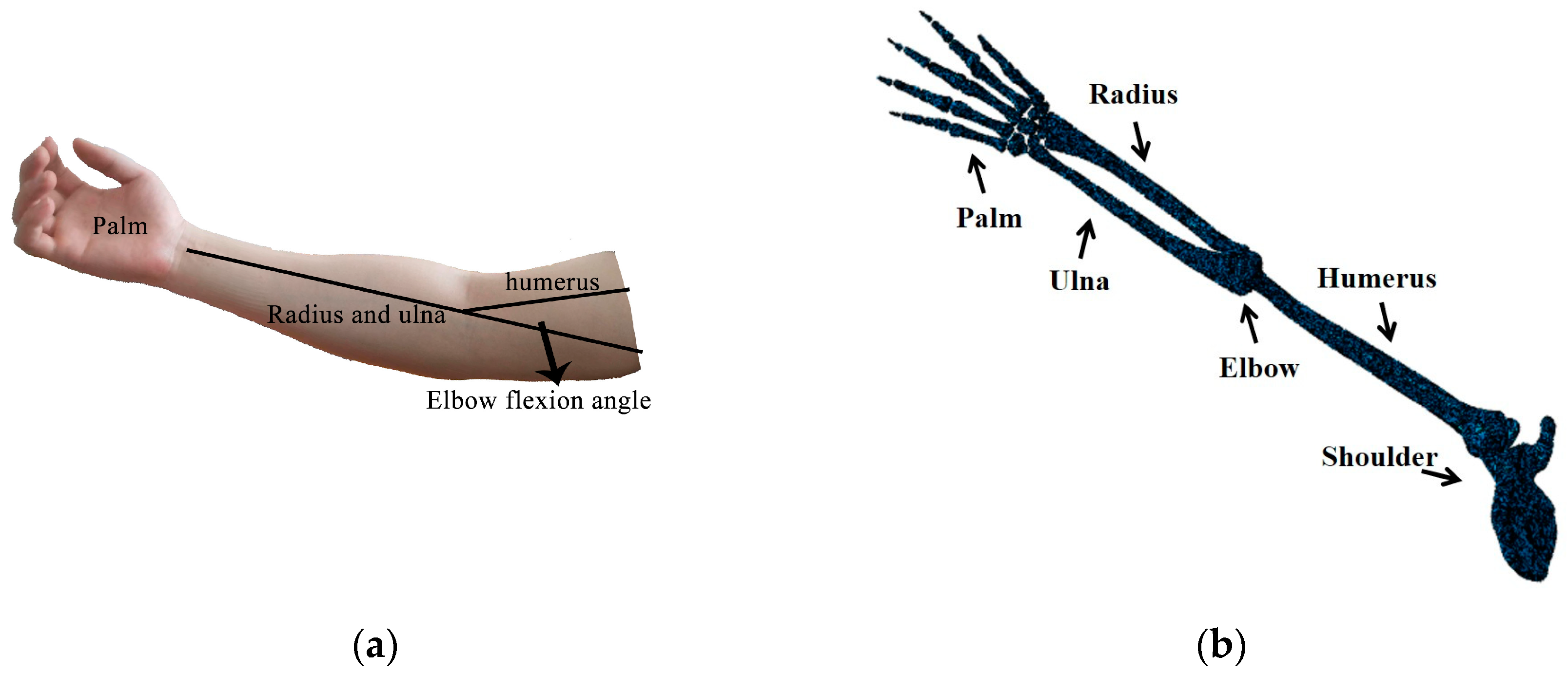
Figure 1. Schematic and skeletal view of the arm: (a) Diagram of the arm; (b) Arm bones.
Mathematics 11 03524 g001
Figure 2. Elbow flexion angle diagram: (a) Elbow flexion 0°; (b) Elbow flexion 25°; (c) Elbow flexion 60°; (d) Elbow flexion 80°.
Mathematics 11 03524 g002
Figure 3. Finite element mesh.
Mathematics 11 03524 g003
Figure 4. The skeletal connections of the elbow.
Mathematics 11 03524 g004
Figure 5. The maximum principal stress of the radius: (a) Elbow flexion 0°−100 N; (b) Elbow flexion 25°−100 N; (c) Elbow flexion 60°−100 N; (d) Elbow flexion 80°−100 N; (e) Elbow flexion 0°−300 N; (f) Elbow flexion 25°−300 N; (g) Elbow flexion 60°−300 N; (h) Elbow flexion 80°−300 N.
Mathematics 11 03524 g005aMathematics 11 03524 g005b
Figure 6. The cross-sectional stress distribution at the maximum principal stress of the radius: (a) Elbow flexion 0°−100 N; (b) Elbow flexion 25°−100 N; (c) Elbow flexion 60°−100 N; (d) Elbow flexion 80°−100 N.
Mathematics 11 03524 g006
Figure 7. Principal stress distribution of the radius.
Mathematics 11 03524 g007
Figure 8. The maximum principal stress of the ulna: (a) Elbow flexion 0°−100 N; (b) Elbow flexion 25°−100 N; (c) Elbow flexion 60°−100 N; (d) Elbow flexion 80°−100 N; (e) Elbow flexion 0°−300 N; (f) Elbow flexion 25°−300 N; (g) Elbow flexion 60°−300 N; (h) Elbow flexion 80°−300 N.
Mathematics 11 03524 g008aMathematics 11 03524 g008b
Figure 9. The cross-sectional stress distribution at the maximum principal stress of the ulna: (a) Elbow flexion 0°−100 N; (b) Elbow flexion 25°−100 N; (c) Elbow flexion 60°−100 N; (d) Elbow flexion 80°−100 N.
Mathematics 11 03524 g009
Figure 10. Principal stress distribution of the ulna.
Mathematics 11 03524 g010
Disclaimer/Publisher’s Note: The statements, opinions and data contained in all publications are solely those of the individual author(s) and contributor(s) and not of MDPI and/or the editor(s). MDPI and/or the editor(s) disclaim responsibility for any injury to people or property resulting from any ideas, methods, instructions or products referred to in the content.