Abstract
This article proposes a discrete proportional-integral-derivative (PID) load frequency control (LFC) scheme to investigate the dissipative analysis issue of restructured wind power systems via a non-fragile design approach. Firstly, by taking the different power-sharing rates of governors into full consideration, a unified model is constructed for interconnected power systems containing multiple governors. Secondly, unlike existing LFC schemes, a non-fragile discrete PID control scheme is designed, which has the performance of tolerating control gain fluctuation and relieving the huge computational burden. Further, by constructing a discrete-type Lyapunov–Krasovskii functional, improved stability criteria with a strict dissipative performance index are established. Finally, numerical examples are presented to demonstrate the effectiveness of the proposed control method.
MSC:
93D05
1. Introduction
Load frequency control (LFC) is an important method for ensuring stability. The two main objectives of its implementation into interconnected power systems are maintaining the frequency and net power interchanges with neighboring areas at the scheduled values, by controlling the area control error (ACE) [1]. In recent years, due to changes in the power system environment and increased complexity and changes in the power system structure, each control area contains different kinds of uncertainties and various disturbances. Abrupt load changes can cause a mismatch between generation and demand, resulting in significant frequency deviations. Some relevant articles have studied the low-frequency oscillation issue of system states [2,3,4]. Therefore, to ensure competitiveness and efficiency in the electricity market, it is necessary to restructure the power system. Generation companies (GENCOs) can choose to participate or not in the task of LFC; there are more forms of cooperation between GENCOs and distribution companies (DISCOs), and any DISCO has the possibility of signing a contract with any GENCO under deregulation. Furthermore, the application of renewable energy is becoming increasingly widespread worldwide. Wind power, as an important renewable energy, makes a great contribution to energy conservation and emission reduction [5]. A restructured power system can help to increase the use of renewable energy sources. When a larger wind power generation replaces the conventional generator, the total inertia of the system decreases, and the equivalent regulation constant increases [6]. Some effective measures have been investigated to solve the previous problems. A novel scheme is developed for wind power modeling regardless of dependency distance in [7] to enhance the system’s ability to handle the variability of wind generation. A supplement controller in a wind power control loop is designed to regulate the rotor speed [8] to remove the fluctuations in output wind power. A novel hidden Markov model is developed to obtain more accurate wind power forecast results [9] to guarantee a safe and reliable system operation. To enhance system damping, an optimized power point tracking controller was proposed [10]. To overcome the problem of high levels of wind power penetration, a model with DFIG-based wind turbines was constructed [11]. To counteract load fluctuations, a robust LFC scheme was designed [12]. Different from the methods mentioned above, the change in the active output in wind power is regarded as a load fluctuation, thus fully mobilizing the regulation capacity of conventional units by controlling the unstable frequency caused by the changes of loads and random fluctuations of wind power. A restructured LFC power system model with wind turbine generator sets is studied in this paper.
Designing suitable methods for LFC is of practical significance to minimize the ACE when load demands fluctuate, and various methods have been proposed in many studies, including a robust delay-dependent PI LFC scheme [13], an event-triggered PI control scheme [14], and a robust decentralized PI control scheme [15]. Considering the practical application, the PID control is more popular in the industry than PI control for its simple structure, strong robustness, and so forth [16]. Various approaches have been taken to design PID control in literature. Singh et al. [17] designed a PID controller with an optimum gain subject to linear matrix inequality (LMI) constraints. J.K. Pradhan and A. Ghosh designed a PID controller with multi-input and multi-output [18]. Pandey et al. [19] proposed a robust iterative PID control scheme. However, these control schemes are unable to deal with the uncertainties in the LFC model. Some researchers have used the non-fragile PID control to solve these problems [20,21]. Non-fragile discrete PID control is designed to provide robust performance by considering uncertainties and disturbances in the system. It can handle parameter variations and disturbances more effectively, leading to improved stability and performance compared to some existing LFC schemes. At the same time, it also limits its effectiveness in capturing complex nonlinear dynamics or dealing with highly uncertain systems for the reason that PID control is based on simple linear models. In addition, there are communication and computational burdens due to some microprocessors with limited computing abilities in the LFC scheme. Discrete control has been surveyed in some articles [22,23,24] because it relieves a huge computational burden and occupies smaller storage space. Therefore, a discrete PID controller is proposed with the time-windows of integral operation over a finite but adjustable length to relieve the computational burden. A non-fragile discrete PID control scheme is designed in this article to provide robust performance and save computing resources.
At present, the dissipativity theory has important applications in many topics such as robust control, regulation, and stabilization. Based on the input–output energy-related theory, strong links between physics and the control theory of systems are given by the dissipativity theory. In order to further analyze and design the control system, a framework is also provided [25]. A number of practical engineering systems have applied the dissipativity theory, for example, mechanical systems [26], robotic manipulators [27], and power systems [28,29]. Additionally, the dissipativity has also been applied in discrete-time networks [30,31] and continuous-time networks [32], respectively. The dissipative concept not only flexibly trades off gain and phase but also provides an appropriate framework for designing less conservative robust controls [33]. The results for a few LFC wind power systems motivated this study in which we consider the dissipative analysis for discrete-time interconnected systems. Dissipativity-based stability conditions consider the energy dissipation rates and their relationship with the system dynamics. By incorporating the dissipative behavior of the system, dissipativity-based stability criteria can capture stability properties more accurately and efficiently, resulting in reduced conservatism [34].
In this work, the main contributions can be summarized as the following three aspects:
- 1.
- A restructured wind power system model is introduced. Compared to some existing models, including single-generator unit models [35], the proposed restructured model introduces new information signals and different controller participation coefficients, resulting in better grid reliability.
- 2.
- A non-fragile discrete PID control scheme for interconnected wind power systems is designed, which can tolerate control gain fluctuation and reduce huge computation costs.
- 3.
- Based on the constructed discrete Lyapunov–Krasovskii functional, strict dissipativity conditions were established for wind power systems. The results can be obtained with lower conservatism and higher computational efficiency.
Notations: denotes the set of natural numbers; denotes the set of positive numbers. Let and represent the n-dimensional Euclidean space and the set of real matrices, respectively. and denote, respectively, the inverse and the transpose of the matrix A. represents the matrix consisting of blocks, and the block in ith row and jth column is . and denote the zero matrix and the identity matrix with dimensions of . means that Q is a positive symmetric definite. stands for the expectation of the stochastic variable , and represents the column vector. Let be a diagonal matrix, i.e., .
2. Preliminaries
This section develops a model of restructured interconnected wind power systems based on a non-fragile discrete PID LFC scheme. In Section 2.1, a model of interconnected wind power systems is constructed. In Section 2.2, a method is investigated to turn the above-mentioned model into a non-fragile discrete model. The parameters involved in the system are defined in Table 1.

Table 1.
Practical meaning of system parameters.
2.1. Restructured LFC Wind Power System Model
Let us define the generation participation matrix (GPM), which shows the participation factor of each Genco in the considered control areas, and each control area is determined by a Disco. For a large-scale power system in Figure 1 with n Gencos, the GPM will have the following structure:
where refers to the generation participation factor and shows the participation factor of Genco i in the load following area j. Meanwhile, . From Figure 1, we can see that
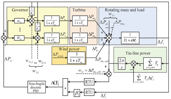
Figure 1.
Interconnected LFC wind power system model.
We can obtain the following equations for the generalized scheduled and
The total generation can be represented as
The model of ith area considering the wind power can be expressed as
Due to the presence of numerous components in the power system that introduce time delays, the inclusion of delay terms was considered in the model development to more accurately depict the dynamic behavior of the system. Define the following vectors
and , we arrive at
where
When taking into account the dotted line connections representing new load demands based on deregulated contracts, one can obtain that
Define
we can obtain that
where
2.2. Non-Fragile Discrete PID LFC Scheme
Different areas in interconnected LFC wind power systems are often associated with digital devices, which send discrete data to their neighboring areas. Define as the sampling interval. Then, one can obtain a discrete state-space model of multi-area as
where , , , , . denotes the discrete time delay of the ith area.
Define , and . Then, a state-space representation of multi-area power systems can be expressed as
where , , , , . , and are the initial conditions.
Then, with the fluctuation in the gain matrices considered, a non-fragile LFC controller is designed as
where the change in proportion deviation can be calculated by , the change in integral deviation can be calculated by , and denotes the change in differential deviation. m is a known scalar representing the length of the time-windows, and it is assumed that in this paper. The mathematical characters , , are assumed to be known as
Define , it follows from (11) that a discrete model can be expressed as
where
where and ( ) are the constant matrices, and is an indeterminate matrix constrained by . The discrete time delay satisfies . represents the lower bound of , and represents the upper bound of , which are all known scalars.
Remark 1.
Multiple generation sets have been introduced into the interconnected wind power system to adjust the turbine input power, they decide the share of the load demands. In the reconstructed model, a reasonable power resource allocation scheme can balance the load requirements of the demand side and the supply side, and new information signals representing the power flow mobility between regions have been proposed, which can improve the efficiency and reliability of frequency regulation.
Remark 2.
Notice that in the above discrete-time controller, three PID controller gain matrices, , , and , are included. Current information and the trend in the information of outputs are well utilized with the introduction of the proportional terms and differential terms . Additionally, history measurements are fully used in the integral term . In particular, compared with the continuous-time controller proposed in [36], a limited but adjusted length of time window is also designed in integral terms of discrete PID to relieve the computational burden.
Remark 3.
Further, non-fragile control schemes are taken into account in the discrete PID controller in (12). , , and describe the occurring status of the perturbation. When , , and , it means that there is no proportion deviation. When , , and , it means that there are multiplicative uncertainties being considered, which better explains the possible gain changes in the implementation process.
Lemma 1
([37]). Given matrices , D, and E with the appropriate dimensions, then
for all satisfying , if and only if there exists a scalar .
3. Results
Based on the model (14) proposed above, this section established dissipativity conditions in Theorem 1. Then, the control gain matrices based on a non-fragile discrete PID control scheme are designed in Theorem 2. This study aims to achieve an analysis of multi-area wind power systems, save limited network resources, and guarantee dissipative control. In the following, the definition of dissipativity is given.
Definition 1
([30]). System (14) is said to be strictly -γ-dissipative if, for any , such that
holds under the zero initial condition. The energy supply rate function is defined as follows.
where , , and are real matrices with , , and .
Based on the discrete-type Lyapunov–Krasovskii functional, sufficient conditions for the control of system (14) are derived in the following theorem for given control feedback gains , , and .
Theorem 1.
For a given integer , , , , , , , , , , , system (14) is strictly -γ-dissipative, if there exist , , , , and , , , Ξ of appropriate dimensions satisfying
where
Proof
(Proof of Theorem 1). Please see Appendix A. □
Remark 4.
In this paper, the discrete-type Lyapunov–Krasovskii functional is a mathematical function that assigns a scalar value to each state, which provides a systematic approach to analyze the stability of discrete-time wind power systems with higher computational efficiency. It is constructed based on the system dynamics and positive definiteness. The functional plays a crucial role in analyzing the stability and designing non-fragile discrete PID controllers for restructured wind power systems. We can see from the proof of Theorem 1 that the stability condition was derived based on the calculation of the forward difference , which deserves some comments. To bring the information of the delay into the final result, the Lyapunov–Krasovskii functional is chosen to be , and the calculation of led to , which was additionally introduced and gave rise to possible conservativeness. We have enlarged it to and to reduce possible conservativeness.
Remark 5.
It is worth mentioning that a strict dissipative analysis problem is more general than some other problems. When , , and , the dissipative properties degenerate into properties strictly, which is shown by a dissipativity analysis. The dissipatiivity analysis in this paper is less conservative than adopted for LFC of power system by most other studies.
Theorem 2.
For a given integer , , , , , , , , , , , system (14) is strictly -γ-dissipative, if there exist , , , , and , , , Ξ of appropriate dimensions satisfying
where
In addition, the PID control feedback gains are given by
Proof
(Proof of Theorem 2). Please see Appendix B. □
4. Illustrative Examples
In this section, the effectiveness of the model proposed in the above section are demonstrated in two parts. In Section 4.1, the effectiveness of the proposed control scheme is considered to be tested by two comparative simulation examples. In Section 4.2, the robustness of the proposed control scheme is validated by using various load disturbances.
4.1. Effectiveness of Non-Fragile Discrete PID LFC
Frequency deviation and tie-line power are key indicators of the system’s response to load changes and generation imbalances. By analyzing the frequency deviation and tie-line power under different operating conditions and disturbances, we can assess the performance of the load frequency control. The goal is to keep the frequency and net power interchanges with neighboring areas at the scheduled values, typically around the nominal value. If the frequency deviations and tie-line power are small and quickly return to the nominal value after disturbances, it indicates effective load frequency control.
In this section, , , and , which are the average success probabilities of the non-fragile items, and the trajectories of and are shown in Figure 2. The time length of the integral loop in the discrete PID controller (12) is taken as , the lower bound of the discrete time delay is taken as , and the upper bound is taken as .
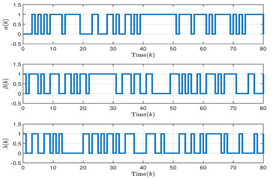
Figure 2.
Trajectories of stochastic variable , , .
Example 1


Table 2.
Parameters of two-area LFC scheme and each including two governors.
The initial states in this example for two areas are defined as , and the fluctuation in the gain matrices of the non-fragile item in the control scheme of two areas are given as
By solving LMI, the solution to matrix inequalities (A15) and (20) in Theorem 2 is computed. Then, the control gains of (14) for two areas are outlined as follows:
In order to better demonstrate the effectiveness of the proposed non-fragile discrete PID in this paper, the responses of the system (14) are shown in Figure 3 and Figure 4 for both the cases considering and not considering uncertainties. Additionally, Figure 5 and Figure 6 describe the control inputs for the two operating conditions mentioned above. From Figure 3 and Figure 4, it can be observed that the proposed non-fragile discrete PID control scheme operates stably and exhibits better control performance compared to other control schemes.
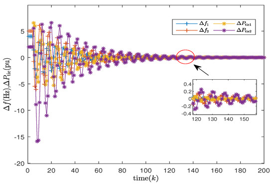
Figure 3.
Frequency deviation and tie-line power of two areas considering uncertainties.
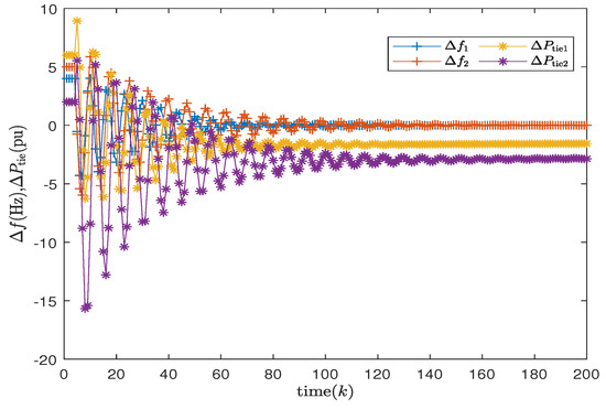
Figure 4.
Frequency deviation and tie-line power of two areas without considering uncertainties.
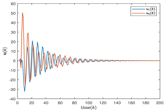
Figure 5.
Control input of two areas considering uncertainties.
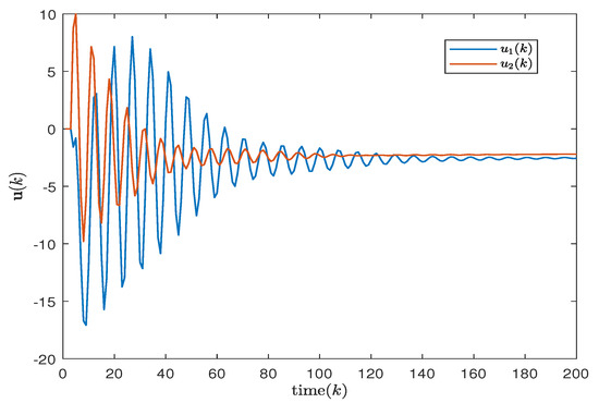
Figure 6.
Control input of two areas without considering uncertainties.
Example 2


Table 3.
Parameters of the three-area LFC scheme and each including two governors.
The initial states in this example for three areas are defined as ; the fluctuation in the gain matrices of the non-fragile item in the control scheme of three areas are given as
Control gains of (12) for three areas are outlined as follows
In this case study, the effectiveness of the non-fragile control scheme was validated through an uncertainty analysis. The simulation results, as shown in Figure 7 and Figure 8, depict the responses of the system (14) in three regions under both uncertain and certain conditions. The input trajectories of the controllers are illustrated in Figure 9 and Figure 10. It is evident that under the design conditions of the non-fragile discrete PID, the system tends to stabilize and exhibits improved performance.
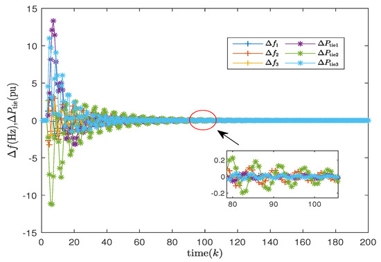
Figure 7.
Frequency deviation and tie-line power of three areas considering uncertainties.
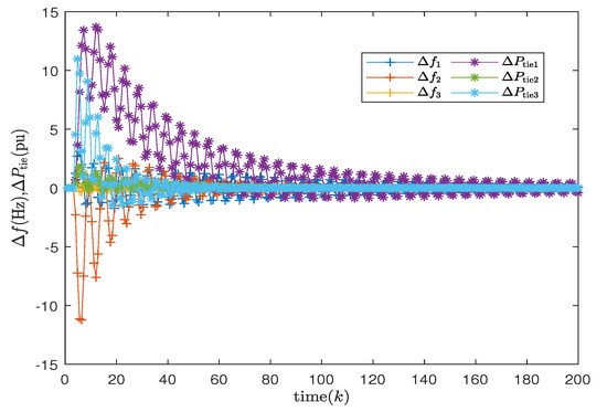
Figure 8.
Frequency deviation and tie-line power of three areas without considering uncertainties.
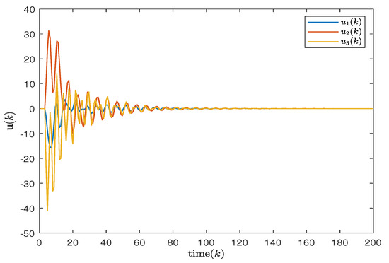
Figure 9.
Control input of three areas considering uncertainties.
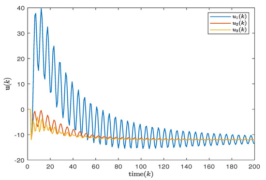
Figure 10.
Control input of three areas without considering uncertainties.
4.2. Case Study of Wind Power System
Robustness assessment involves analyzing the performance of load frequency control under various operating conditions, parameter uncertainties, and disturbances. The control strategy demonstrates resilience and effectiveness in handling uncertainties and disturbances while maintaining system stability and desired frequency response. This section tests the system responses for different scenarios, including possible different bilateral contracts (GPM), wind power system is as shown in the Figure 11.
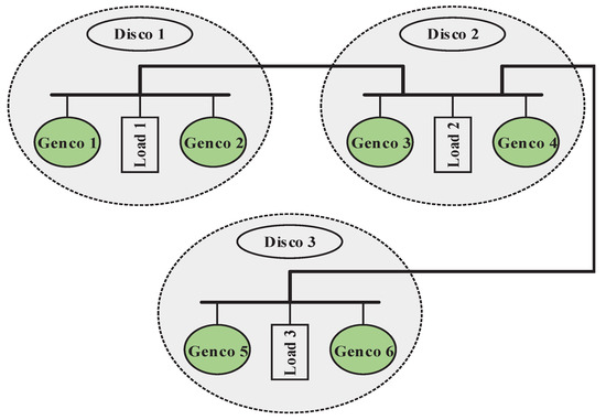
Figure 11.
Wind power system of three areas.
Case 1: As the first test scenario, the following step load disturbances were applied to two areas: MW and MW. From to , no disturbances were present in the system, and, at , a disturbance satisfying the previous condition was introduced. The GPM is given as follows:
As can be seen from Figure 12, the system finally reached stability under the conditions of Case 1.
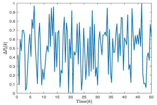
Figure 12.
Trajectories of load disturbances.
Case 2: Generally, load disturbances in wind power systems are uncertain. Therefore, it is necessary to test the effectiveness of the controller considering randomly varying load disturbances. For simulation, the uncertainty of load disturbance for each region is calculated by using: , where R is a random number satisfying . The random load disturbance is shown in Figure 12, and it is applied in the system from . Given the signing rules between Discos and the available Gencos in other areas as the following GPM:
The simulation results confirm that the output signal eventually tends to zero, thus demonstrating the stability of the proposed system under random load disturbance.
The output signal of the area controlled can be seen in Figure 13, which indicates that the proposed control scheme can effectively achieve stability under various load fluctuations. The simulation results establish the efficacy of the suggested controller in moderating frequency deviation and tie-line power change in the restructured environment.
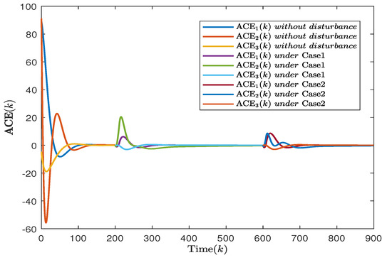
Figure 13.
ACE of ith area under different load disturbances.
5. Conclusions
This paper has designed an LFC for reconstructed power systems containing multiple generation sets. Firstly, a restructured wind power system model has been introduced, which incorporated competition among market participants and provided a favorable environment for the integration of wind power into the grid to maintain grid reliability. Then, in order to relieve the computation burden of the system, a discrete PID control scheme has been designed. Moreover, considering the fluctuation in the gain matrices, the non-fragile model has been adopted to describe this phenomenon. Finally, two cases of wind power systems have been given to demonstrate the effectiveness of the proposed control approach under sufficient conditions to satisfy dissipativity. The proposed control scheme has also been verified by numerical examples.
Author Contributions
Conceptualization, H.Z., Q.Z., S.H., J.Y., K.S. and S.Z.; methodology, H.Z., Q.Z., S.H. and J.Y.; software, H.Z., Q.Z., S.H. and J.Y.; validation, Q.Z., K.S. and S.Z.; formal analysis, H.Z. and Q.Z.; investigation, H.Z., Q.Z., S.H. and J.Y.; resources, Q.Z. and K.S.; data curation, H.Z., Q.Z. and S.H.; writing—original draft preparation, H.Z.; writing—review and editing, H.Z., Q.Z., S.H., J.Y., K.S. and S.Z.; visualization, H.Z.; supervision, J.Y., K.S. and S.Z.; project administration, Q.Z., K.S. and S.Z. All authors have read and agreed to the published version of the manuscript.
Funding
This research was funded by the Sichuan Science and Technology Plan of funder grant number No. 2021ZDZX0003 and No.2022ZHCG0115; the China Postdoctoral Science Foundation of funder grant number No. 2020M683274 and No. 2021T140092; the Open Research Project of the State Key Laboratory of Industrial Control Technology, Zhejiang University, China, of funder grant number No. ICT2021B38; Guangdong Basic and Applied Basic Research Foundation of funder grant number No. 2021A1515011692; and the Program of Science and Technology of Sichuan Province of China of funder grant number No. 2021ZYD0012.
Data Availability Statement
The data presented in this study are available on request from the corresponding author.
Conflicts of Interest
The authors declare no conflict of interest. The funders had no role in the design of this study; in the collection, analyses, or interpretation of data; in the writing of the manuscript; or in the decision to publish the results.
Appendix A
Proof
(Proof of Theorem 1). A discrete-type Lyapunov–Krasovskii functional is constructed to analyze the dissipativity of the system (14) as follows.
where
By calculating the difference between and taking the mathematical expectation along the trajectory of system (14), we have
where
Applying the elementary inequality (where a and b are vectors of compatible dimensions) to the term , one obtains
By using the Schur complement, one can obtain
It can be seen that if (A14) satisfies the inequalities (18) and (19), we can draw the following conclusions
Taking summation on both sides of (A15) from 0 to yields
Under the zero initial condition , we have
Appendix B
Proof
(Proof of Theorem 2). Define
where
To eliminate uncertainty , two matrices are given as
where
Therefore, Formula (18) can be rewritten as
Formula (A20) is equivalent to (A21) based on Lemma 1
and Formula (A22) is equivalent to (A21) by the Schur complement
where
In the following steps, we will design the control feedback gains of system (14). Define , , . Pre- and postmultiply both sides of (A22) by ℧ and its transposition. Pre- and postmultiply both sides of (19) by . This is how (20) and (21) can be obtained.
Define
based on the above definition of , , , there exists difficulty to obtain , , and directly because the matrix C is not invertible. By defining , and , refer to the method in [39]. The above problem can be solved by transforming it into the W-problem. We obtain , according to the method in [40]. By using the Schur complement, we have the following optimization problem:
where is a small enough positive scalar. What is obtained from matrix is the full row rank, that is, matrix is full rank and invertible. Therefore, we can design control gains , , and on the following results. Then, the system (14) is strictly --dissipative, and the feedback gains are obtained as . The proof of Theorem 2 is complete. □
References
- Pandey, S.K.; Mohanty, S.R.; Kishor, N. A literature survey on LFC for conventional and distribution generation power systems. Renew. Sustain. Energ. Rev. 2013, 25, 318–334. [Google Scholar] [CrossRef]
- Wang, Q.; Yu, Y.; Zhang, Z.; Han, X. Melnikov-threshold-triggered mixed-mode oscillations in a family of amplitude-modulated forced oscillator. J. Low Freq. Noise Vib. Act. Control 2019, 38, 377–387. [Google Scholar] [CrossRef]
- Yu, Y.; Wang, Q.; Bi, Q.; Lim, C.W. Multiple-s-shaped critical manifold and jump phenomena in low frequency forced vibration with amplitude modulation. Int. J. Bifurcat. Chaos 2019, 29, 1930012. [Google Scholar] [CrossRef]
- Sun, L.; Zhang, C.; Yu, Y. A boundary knot method for 3D time harmonic elastic wave problems. Appl. Math. Lett. 2020, 104, 106210. [Google Scholar] [CrossRef]
- Li, Y.; Ni, Z.; Zhao, T.; Yu, M.; Liu, Y.; Wu, L.; Zhao, Y. Coordinated scheduling for improving uncertain wind power adsorption in electric vehicles-wind integrated power systems by multiobjective optimization approach. IEEE Trans. Ind. Appl. 2020, 56, 2238–2250. [Google Scholar] [CrossRef]
- Nguyen, N.; Mitra, J. An analysis of the effects and dependency of wind power penetration on system frequency regulation. IEEE Trans. Sustain. Energy 2016, 7, 354–363. [Google Scholar] [CrossRef]
- Li, M.; Yang, M.; Yu, Y.; Lee, W.J. A wind speed correction method based on modified hidden Markov model for enhancing wind power forecast. IEEE Trans. Ind. Appl. 2022, 58, 656–666. [Google Scholar] [CrossRef]
- Liao, K.; Lu, D.; Wang, M.; Yang, J. A low-pass virtual filter for output power smoothing of wind energy conversion systems. IEEE Trans. Ind. Electron. 2022, 69, 12874–12885. [Google Scholar] [CrossRef]
- Sun, S.; Liu, Y.; Li, Q.; Wang, T.; Chu, F. Short-term multi-step wind power forecasting based on spatio-temporal correlations and transformer neural networks. Energy Convers. Manag. 2023, 283, 116916. [Google Scholar] [CrossRef]
- Wang, Y.; Meng, J.; Zhang, X.; Xu, L. Control of PMSG-based wind turbines for system inertial response and power oscillation damping. IEEE Trans. Sustain. Energy 2015, 6, 565–574. [Google Scholar] [CrossRef]
- Chen, C.; Su, Y.; Yang, T.; Huang, Z. Virtual inertia coordination control strategy of DFIG-based wind turbine for improved grid frequency response ability. Electr. Power Syst. Res. 2023, 216, 109076. [Google Scholar] [CrossRef]
- Vachirasricirikul, S.; Ngamroo, I. Robust LFC in a smart grid with wind power penetration by coordinated vehicle-to-grid control and frequency controller. IEEE Trans. Smart Grid 2014, 5, 371–380. [Google Scholar] [CrossRef]
- Shangguan, X.C.; Zhang, C.K.; He, Y.; Jin, L.; Jiang, L.; Spencer, J.W.; Wu, M. Robust LFC for power system considering transmission delay and sampling period. IEEE Trans. Ind. Inform. 2021, 17, 5292–5303. [Google Scholar] [CrossRef]
- Peng, C.; Li, J.; Fei, M. Resilient event-Triggering H∞ LFC for multi-Area power systems with energy-limited DoS attacks. IEEE Trans. Power Syst. 2017, 32, 4110–4118. [Google Scholar] [CrossRef]
- Bevrani, H.; Hiyama, T. Robust decentralised PI based LFC design for time delay power systems. Energy Convers. Manag. 2008, 49, 193–204. [Google Scholar] [CrossRef]
- Ang, K.H.; Chong, G.; Li, Y. PID control system analysis, design, and technology. IEEE Trans. Control Syst. Technol. 2005, 13, 559–576. [Google Scholar]
- Singh, V.P.; Kishor, N.; Samuel, P. Improved LFC of power system using LMI based PID approach. J. Frankl. Inst. 2017, 354, 6805–6830. [Google Scholar] [CrossRef]
- Pradhan, J.K.; Ghosh, A. Multi-input and multi-output PID controller design via linear quadratic regulator-linear matrix inequality approach. IET Control Theory Appl. 2015, 9, 2140–2145. [Google Scholar] [CrossRef]
- Pandey, S.K.; Kishor, N.; Mohanty, S.R. Frequency regulation in hybrid power system using iterative PID H∞ controller. Electr. Power Compon. Syst. 2014, 42, 132–148. [Google Scholar] [CrossRef]
- Zhong, Q.; Yang, J.; Shi, K.; Zhong, S.; Li, Z.; Sotelo, M.A. Event-triggered H∞ LFC for multi-area nonlinear power systems based on non-fragile proportional integral control strategy. IEEE Trans. Intell. Transp. Syst. 2022, 23, 12191–12201. [Google Scholar] [CrossRef]
- Elsisi, M.; Soliman, M. Optimal design of robust resilient automatic voltage regulators. ISA Trans. 2021, 108, 257–268. [Google Scholar] [CrossRef] [PubMed]
- Wang, Y.; Zou, L.; Zhao, Z.; Bai, X. H∞ fuzzy PID control for discrete time-delayed T-S fuzzy systems. Neurocomputing 2019, 332, 91–99. [Google Scholar] [CrossRef]
- Zhao, D.; Wang, Z.; Wei, G.; Han, Q.L. A dynamic event-triggered approach to observer-based PID security control subject to deception attacks. Automatica 2020, 120, 109128. [Google Scholar] [CrossRef]
- Shen, H.; Xing, M.; Xu, S.; Basin, M.V.; Park, J.H. H∞ stabilization of discrete-time nonlinear semi-Markov jump singularly perturbed systems with partially known semi-Markov Kernel information. IEEE Trans. Circuits Syst. I Reg. Pap. 2021, 68, 818–828. [Google Scholar] [CrossRef]
- Feng, Z.; Lam, J.; Gao, H. α-Dissipativity analysis of singular time-delay systems. Automatica 2011, 47, 2548–2552. [Google Scholar] [CrossRef]
- Bullo, F. Averaging and vibrational control of mechanical systems. SIAM J. Control Optim. 2002, 41, 542–562. [Google Scholar] [CrossRef]
- Fantoni, I.; Lozano, R.; Spong, M. Energy based control of the Pendubot. IEEE Trans. Autom. Control 2000, 45, 725–729. [Google Scholar] [CrossRef]
- Wang, Y.; Cheng, D.; Li, C.; Ge, Y. Dissipative Hamiltonian realization and energy-based L2-disturbance attenuation control of multimachine power systems. IEEE Trans. Autom. Control 2003, 48, 1428–1433. [Google Scholar] [CrossRef]
- Galaz, M.; Ortega, R.; Bazanella, A.S.; Stankovic, A.M. An energy-shaping approach to the design of excitation control of synchronous generators. Automatica 2003, 39, 111–119. [Google Scholar] [CrossRef]
- Wu, Z.G.; Shi, P.; Su, H.; Chu, J. Dissipativity Analysis for Discrete-Time Stochastic Neural Networks With Time-Varying Delays. IEEE Trans. Neural Netw. Learn. Syst. 2013, 24, 345–355. [Google Scholar] [CrossRef]
- Wang, J.; Huang, Z.; Wu, Z.; Cao, J.; Shen, H. Extended dissipative control for singularly perturbed PDT switched systems and its application. IEEE Trans. Circuits Syst. I Reg. Pap. 2020, 67, 5281–5289. [Google Scholar] [CrossRef]
- Feng, Z.; Lam, J. Stability and dissipativity analysis of distributed delay cellular neural networks. IEEE Trans. Neural Netw. Learn. Syst. 2011, 22, 976–981. [Google Scholar] [CrossRef]
- Meisami-Azad, M.; Mohammadpour, J.; Grigoriadis, K.M. Dissipative analysis and control of state-space symmetric systems. Automatica 2009, 45, 1574–1579. [Google Scholar] [CrossRef]
- Willems, J.C. Dissipative dynamical systems part I: General theory. Arch. Ration. Mech. Anal. 1972, 45, 321–351. [Google Scholar] [CrossRef]
- Peng, C.; Zhang, J.; Yan, H. Adaptive event-triggering H∞ LFC for network-based power systems. IEEE Trans. Ind. Electron. 2018, 65, 1685–1694. [Google Scholar] [CrossRef]
- Jin, L.; He, Y.; Zhang, C.K.; Shangguan, X.C.; Jiang, L.; Wu, M. Novel structure-exploiting techniques based delay-dependent stability analysis of multi-area LFC with improved numerical tractability. IEEE Trans. Power Syst. 2021, 36, 4194–4211. [Google Scholar] [CrossRef]
- Li, T.; Guo, L.; Sun, C. Robust stability for neural networks with time-varying delays and linear fractional uncertainties. Neurocomputing 2007, 71, 421–427. [Google Scholar] [CrossRef]
- Jin, L.; He, Y.; Zhang, C.K.; Shangguan, X.C.; Jiang, L.; Wu, M. Robust delay-dependent LFC of wind power system based on a novel reconstructed model. IEEE Trans. Cybern. 2021, 52, 7825–7836. [Google Scholar] [CrossRef]
- Crusius, C.; Trofino, A. Sufficient LMI conditions for output feedback control problems. IEEE Trans. Autom. Control 1999, 44, 1053–1057. [Google Scholar] [CrossRef]
- Peng, C.; Zhang, J. Delay-distribution-dependent LFC of power systems with probabilistic interval delays. IEEE Trans. Power Syst. 2016, 31, 3309–3317. [Google Scholar] [CrossRef]
Disclaimer/Publisher’s Note: The statements, opinions and data contained in all publications are solely those of the individual author(s) and contributor(s) and not of MDPI and/or the editor(s). MDPI and/or the editor(s) disclaim responsibility for any injury to people or property resulting from any ideas, methods, instructions or products referred to in the content. |
© 2023 by the authors. Licensee MDPI, Basel, Switzerland. This article is an open access article distributed under the terms and conditions of the Creative Commons Attribution (CC BY) license (https://creativecommons.org/licenses/by/4.0/).