
Mobile Robot Navigation Based on Embedded Computer Vision

 ,
,  ,
,  ,
,  and
and
Abstract
1. Introduction
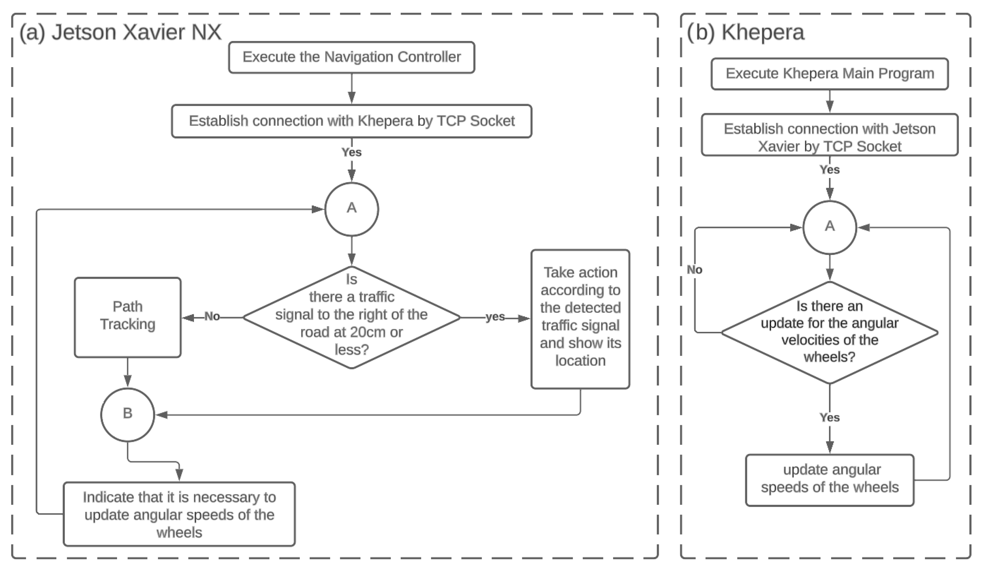
- The development of an embedded system that integrates the Khepera and Jetson Xavier NX, both systems exchanging information by TCP Socket. To the best of our knowledge, our work is the first solution that links the Khepera and the Jetson Xavier NX to implement a navigation DDRM based on trajectory tracking and object detection.
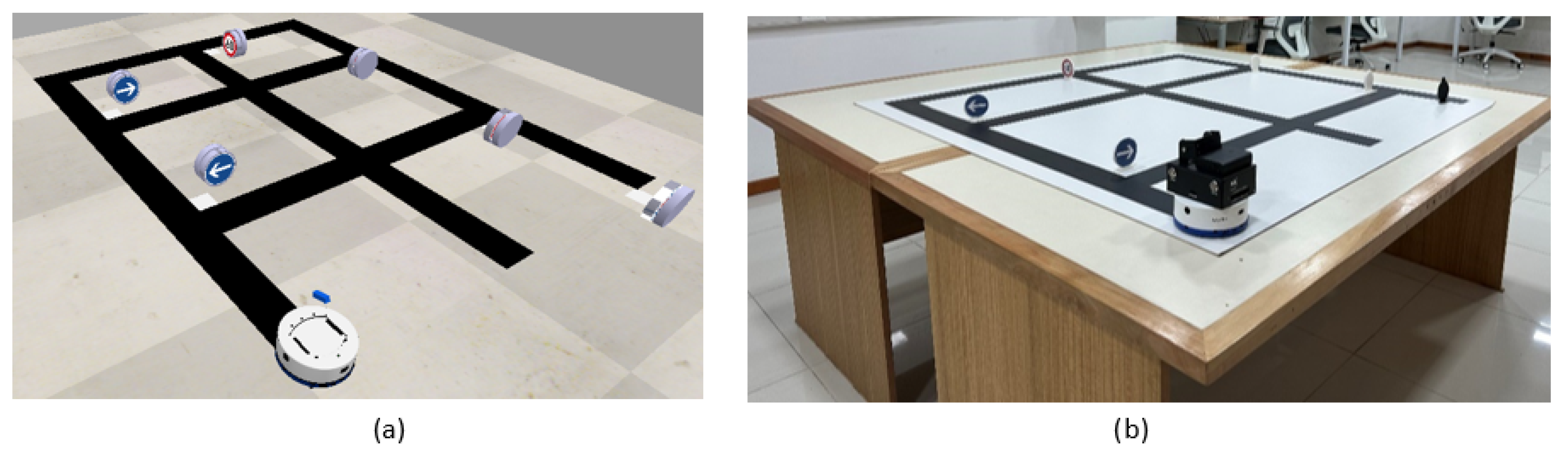
- The construction of a robotic platform for testing algorithms based on image processing for trajectory tracking and real-time object detection models.
- The verification of the technical feasibility of using the YOLOv5 architecture and its potential to generate models using transfer learning so that they can be used by an embedded system with GPU, managing to create robust intelligent systems in a shorter amount of time.
- The proposed system presents an improvement with respect to previous works, as our approach increases the speed of the robot by improving the success rate of object recognition.
2. Problem Statement and Proposed Solution
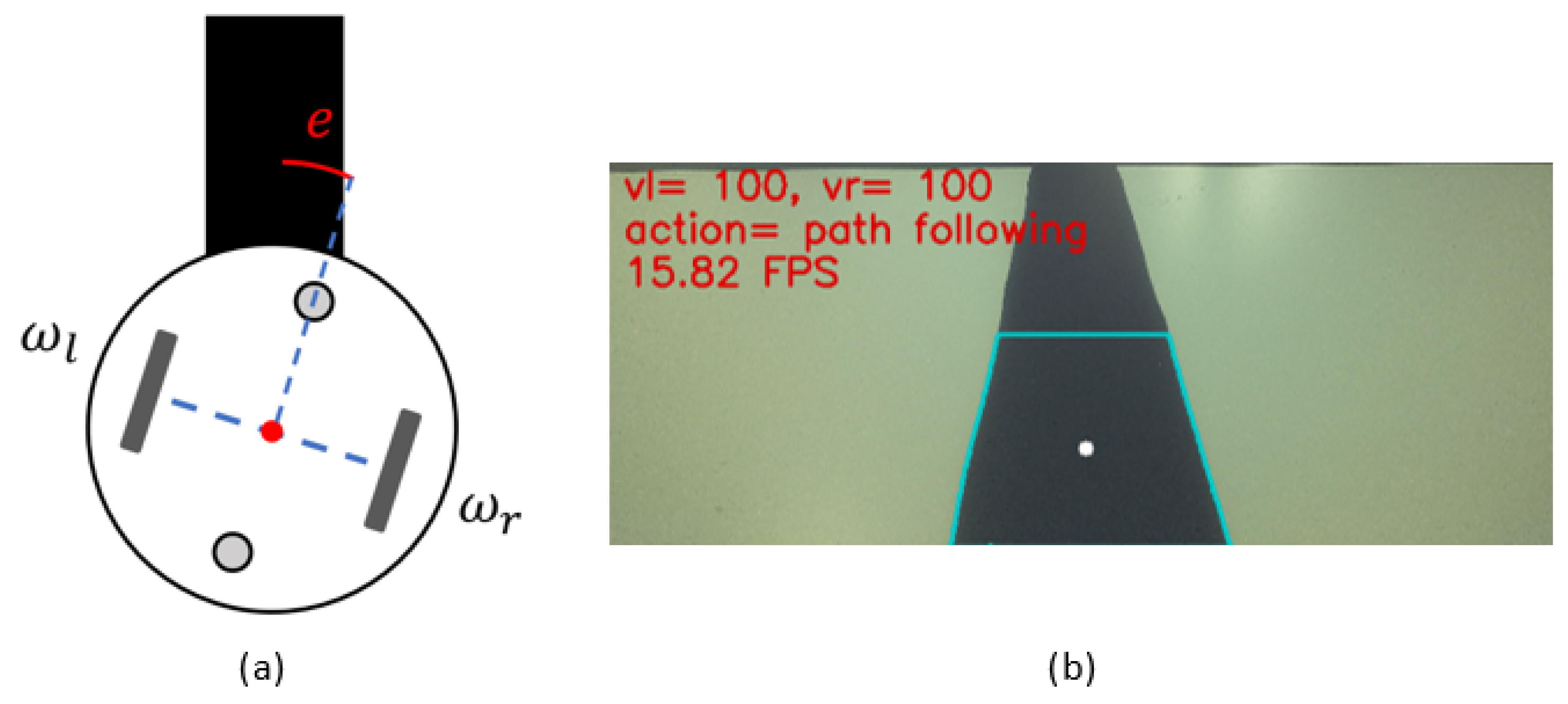
2.1. Kinematic Model
- The robot moves on a flat surface.
- The wheel slip must be negligible.
- The robot is rigid with no flexible parts.
- There are internal control loops to achieve the commanded speeds.
2.2. Path Tracking
- Filter the areas that are not the color of the road because they will not be analyzed.
- Select the area of the road color with the largest area.
- Identify the center of that region, and its value is taken in x (it is where the variation can be given by error).
- Calculate the error between the location of the center of the road and the center of the camera (e); this is normalized to take values between 0 and 1.
- Estimate the new angular speed () needed to adjust the direction of the Khepera, as well as the linear speed (V), needed for its advance, using the following equations:
2.3. Object Detection
- CPU: Intel Core i9-10900X.
- lGPU: RTX2080, comes with 8 GB of GDDR6 memory.
- RAM: 64 GB.
- Storage: 1 TB.
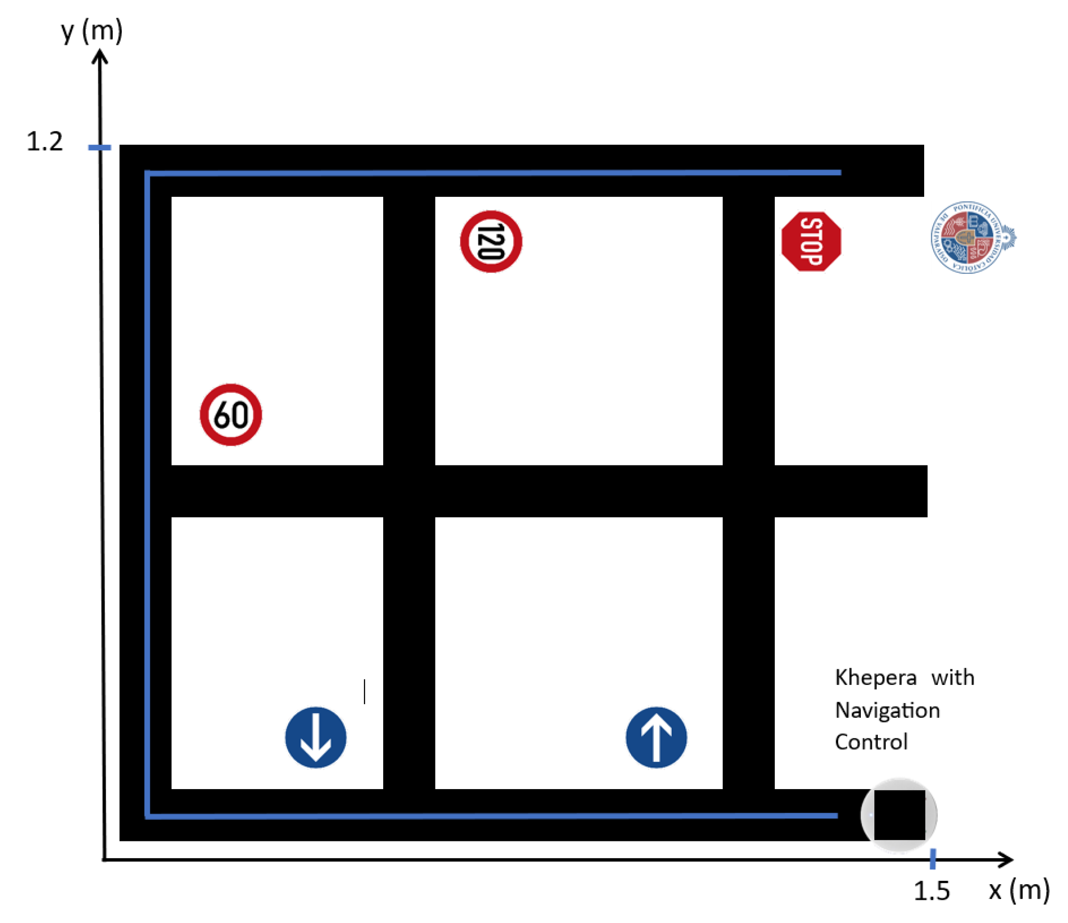
3. Final Implementation of Navigation Control and Experimentation
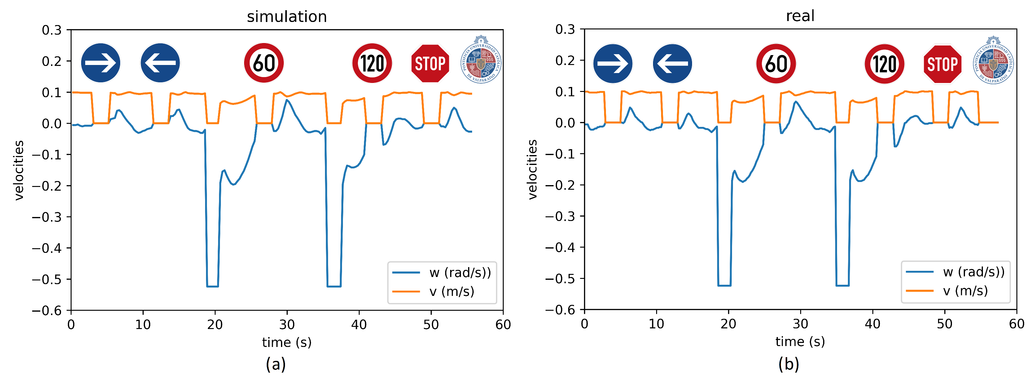
3.1. Scene 1
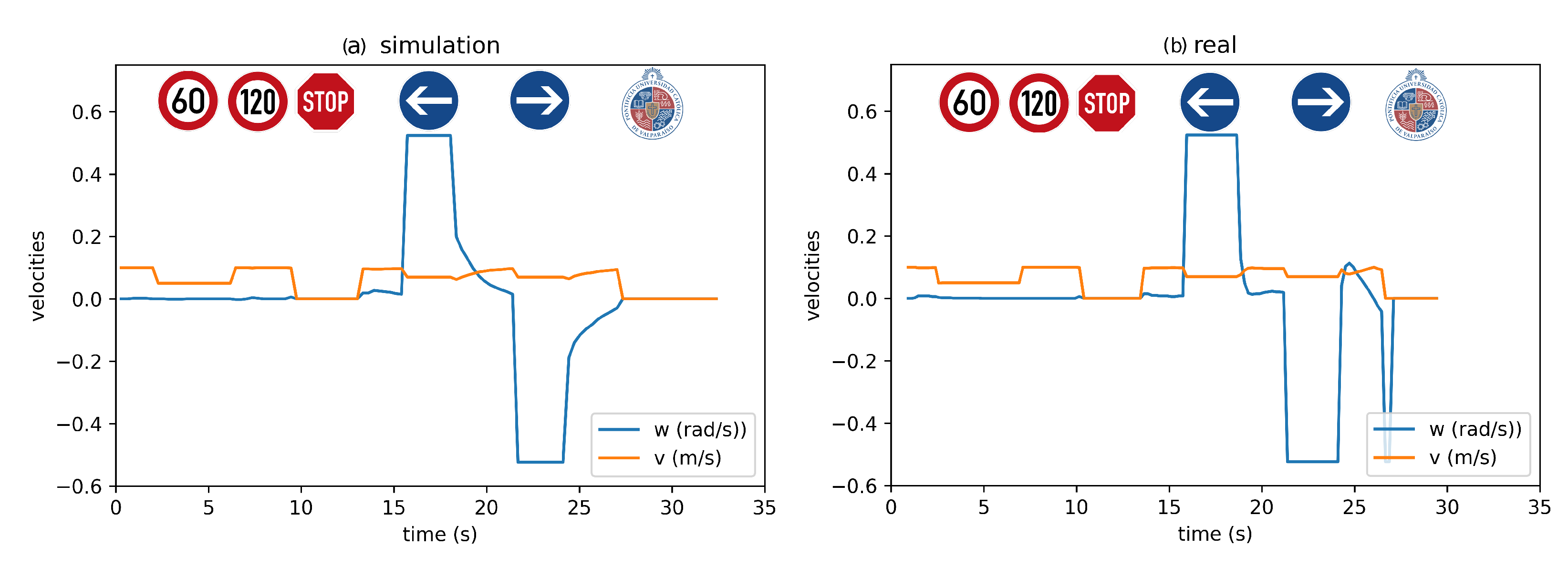
3.2. Scene 2
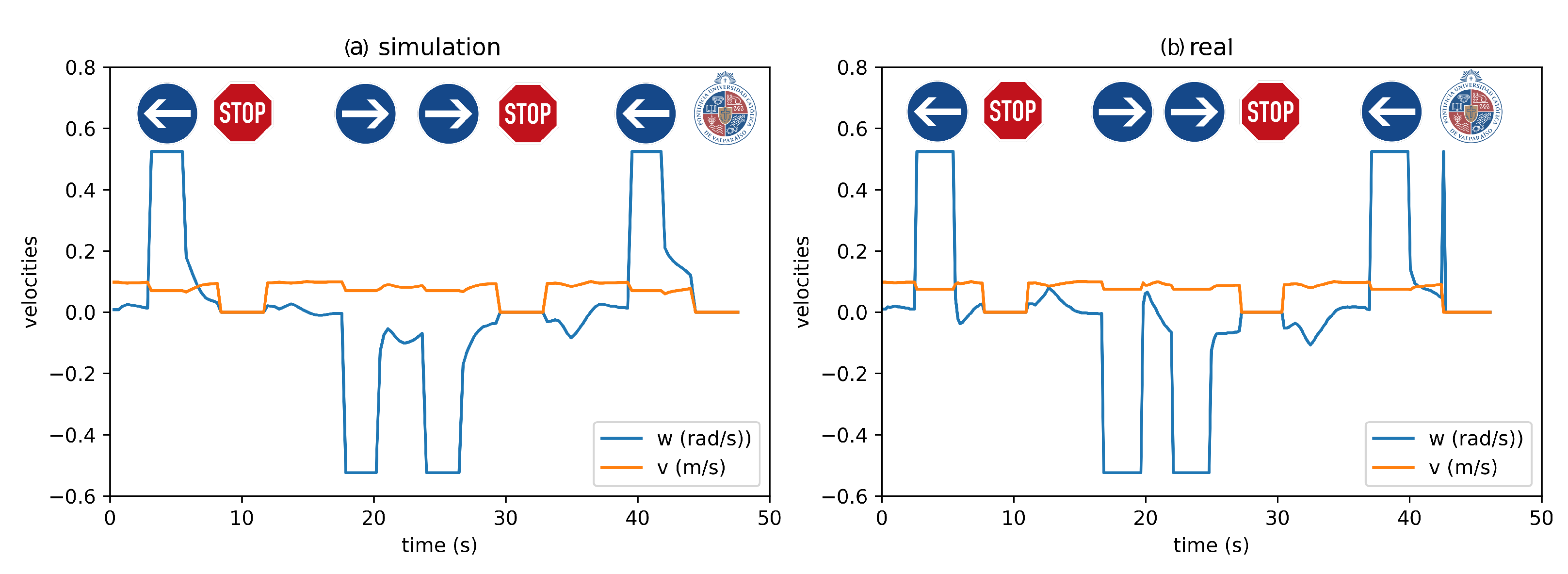
3.3. Scene 3
4. Conclusions
Author Contributions
Funding
Data Availability Statement
Acknowledgments
Conflicts of Interest
References
- Lee, I. Service Robots: A Systematic Literature Review. Electronics 2021, 10, 2658. [Google Scholar] [CrossRef]
- Montoya-Cavero, L.E.; Díaz de León Torres, R.; Gómez-Espinosa, A.; Escobedo Cabello, J.A. Vision systems for harvesting robots: Produce detection and localization. Comput. Electron. Agric. 2022, 192, 106562. [Google Scholar] [CrossRef]
- Kim, J.; Mishra, A.K.; Limosani, R.; Scafuro, M.; Cauli, N.; Santos-Victor, J.; Mazzolai, B.; Cavallo, F. Control strategies for cleaning robots in domestic applications: A comprehensive review. Int. J. Adv. Robot. Syst. 2019, 16, 1729881419857432. [Google Scholar] [CrossRef]
- Sun, Z.; Xie, H.; Zheng, J.; Man, Z.; He, D. Path-following control of Mecanum-wheels omnidirectional mobile robots using nonsingular terminal sliding mode. Mech. Syst. Signal Process. 2021, 147, 107128. [Google Scholar] [CrossRef]
- Chen, G.; Yang, X.; Xu, Y.; Lu, Y.; Hu, H. Neural network-based motion modeling and control of water-actuated soft robotic fish. Smart Mater. Struct. 2022, 32, 015004. [Google Scholar] [CrossRef]
- Chen, G.; Xu, Y.; Yang, C.; Yang, X.; Hu, H.; Chai, X.; Wang, D. Design and control of a novel bionic mantis shrimp robot. IEEE/ASME Trans. Mechatron. 2023. early access. [Google Scholar] [CrossRef]
- Rubio, F.; Valero, F.; Llopis-Albert, C. A review of mobile robots: Concepts, methods, theoretical framework, and applications. Int. J. Adv. Robot. Syst. 2019, 16, 1729881419839596. [Google Scholar] [CrossRef]
- Montenegro, G.; Chacón, R.; Fabregas, E.; Garcia, G.; Schröder, K.; Marroquín, A.; Dormido-Canto, S.; Farias, G. Modeling and Control of a Spherical Robot in the CoppeliaSim Simulator. Sensors 2022, 22, 6020. [Google Scholar] [CrossRef]
- Schröder, K.; Garcia, G.; Chacón, R.; Montenegro, G.; Marroquín, A.; Farias, G.; Dormido-Canto, S.; Fabregas, E. Development and Control of a Real Spherical Robot. Sensors 2023, 23, 3895. [Google Scholar] [CrossRef]
- Stefek, A.; Pham, T.V.; Krivanek, V.; Pham, K.L. Energy Comparison of Controllers Used for a Differential Drive Wheeled Mobile Robot. IEEE Access 2020, 8, 170915–170927. [Google Scholar] [CrossRef]
- Fabregas, E.; Farias, G.; Aranda-Escolástico, E.; Garcia, G.; Chaos, D.; Dormido-Canto, S.; Bencomo, S.D. Simulation and experimental results of a new control strategy for point stabilization of nonholonomic mobile robots. IEEE Trans. Ind. Electron. 2019, 67, 6679–6687. [Google Scholar] [CrossRef]
- Moysiadis, V.; Tsolakis, N.; Katikaridis, D.; Sørensen, C.G.; Pearson, S.; Bochtis, D. Mobile Robotics in Agricultural Operations: A Narrative Review on Planning Aspects. Appl. Sci. 2020, 10, 3453. [Google Scholar] [CrossRef]
- Gravina, R.; Alinia, P.; Ghasemzadeh, H.; Fortino, G. Multi-sensor fusion in body sensor networks: State-of-the-art and research challenges. Inf. Fusion 2017, 35, 68–80. [Google Scholar] [CrossRef]
- Sun, J.; Zhao, J.; Hu, X.; Gao, H.; Yu, J. Autonomous Navigation System of Indoor Mobile Robots Using 2D Lidar. Mathematics 2023, 11, 1455. [Google Scholar] [CrossRef]
- Mújica-Vargas, D.; Vela-Rincón, V.; Luna-Álvarez, A.; Rendón-Castro, A.; Matuz-Cruz, M.; Rubio, J. Navigation of a Differential Wheeled Robot Based on a Type-2 Fuzzy Inference Tree. Machines 2022, 10, 660. [Google Scholar] [CrossRef]
- Kim, J.; Kim, B.K. Cornering Trajectory Planning Avoiding Slip for Differential-Wheeled Mobile Robots. IEEE Trans. Ind. Electron. 2020, 67, 6698–6708. [Google Scholar] [CrossRef]
- Dell’Agnola, F.; Jao, P.K.; Arza, A.; Chavarriaga, R.; Millán, J.d.R.; Floreano, D.; Atienza, D. Machine-Learning Based Monitoring of Cognitive Workload in Rescue Missions With Drones. IEEE J. Biomed. Health Inform. 2022, 26, 4751–4762. [Google Scholar] [CrossRef] [PubMed]
- Abdelwahab, M.; Parque, V.; Fath Elbab, A.M.R.; Abouelsoud, A.A.; Sugano, S. Trajectory Tracking of Wheeled Mobile Robots Using Z-Number Based Fuzzy Logic. IEEE Access 2020, 8, 18426–18441. [Google Scholar] [CrossRef]
- Štefek, A.; Pham, V.T.; Krivanek, V.; Pham, K.L. Optimization of Fuzzy Logic Controller Used for a Differential Drive Wheeled Mobile Robot. Appl. Sci. 2021, 11, 6023. [Google Scholar] [CrossRef]
- Babunski, D.; Berisha, J.; Zaev, E.; Bajrami, X. Application of Fuzzy Logic and PID Controller for Mobile Robot Navigation. In Proceedings of the 2020 9th Mediterranean Conference on Embedded Computing (MECO), Budva, Montenegro, 8–11 June 2020. [Google Scholar] [CrossRef]
- Luis, C.E.; Vukosavljev, M.; Schoellig, A.P. Online Trajectory Generation With Distributed Model Predictive Control for Multi-Robot Motion Planning. IEEE Robot. Autom. Lett. 2020, 5, 604–611. [Google Scholar] [CrossRef]
- Yudha, H.M.; Dewi, T.; Hasana, N.; Risma, P.; Oktarini, Y.; Kartini, S. Performance Comparison of Fuzzy Logic and Neural Network Design for Mobile Robot Navigation. In Proceedings of the 2019 International Conference on Electrical Engineering and Computer Science (ICECOS), Batam, Indonesia, 2–3 October 2019. [Google Scholar] [CrossRef]
- Wang, T.; Chen, B.; Zhang, Z.; Li, H.; Zhang, M. Applications of machine vision in agricultural robot navigation: A review. Comput. Electron. Agric. 2022, 198, 107085. [Google Scholar] [CrossRef]
- Jiang, H.; Wang, H.; Yau, W.Y.; Wan, K.W. A Brief Survey: Deep Reinforcement Learning in Mobile Robot Navigation. In Proceedings of the 2020 15th IEEE Conference on Industrial Electronics and Applications (ICIEA), Kristiansand, Norway, 9–13 November 2020. [Google Scholar] [CrossRef]
- Pokle, A.; Martín-Martín, R.; Goebel, P.; Chow, V.; Ewald, H.M.; Yang, J.; Wang, Z.; Sadeghian, A.; Sadigh, D.; Savarese, S.; et al. Deep Local Trajectory Replanning and Control for Robot Navigation. In Proceedings of the 2019 International Conference on Robotics and Automation (ICRA), Montreal, QC, Canada, 20–24 May 2019. [Google Scholar] [CrossRef]
- De Micco, L.; Vargas, F.L.; Fierens, P.I. A Literature Review on Embedded Systems. IEEE Lat. Am. Trans. 2020, 18, 188–205. [Google Scholar] [CrossRef]
- Branco, S.; Ferreira, A.G.; Cabral, J. Machine Learning in Resource-Scarce Embedded Systems, FPGAs, and End-Devices: A Survey. Electronics 2019, 8, 1289. [Google Scholar] [CrossRef]
- Karalekas, G.; Vologiannidis, S.; Kalomiros, J. EUROPA: A Case Study for Teaching Sensors, Data Acquisition and Robotics via a ROS-Based Educational Robot. Sensors 2020, 20, 2469. [Google Scholar] [CrossRef] [PubMed]
- Ajani, T.S.; Imoize, A.L.; Atayero, A.A. An Overview of Machine Learning within Embedded and Mobile Devices–Optimizations and Applications. Sensors 2021, 21, 4412. [Google Scholar] [CrossRef]
- Farias, G.; Fabregas, E.; Peralta, E.; Vargas, H.; Dormido-Canto, S.; Dormido, S. Development of an Easy-to-Use Multi-Agent Platform for Teaching Mobile Robotics. IEEE Access 2019, 7, 55885–55897. [Google Scholar] [CrossRef]
- Farias, G.; Fabregas, E.; Peralta, E.; Vargas, H.; Hermosilla, G.; Garcia, G.; Dormido, S. A Neural Network Approach for Building An Obstacle Detection Model by Fusion of Proximity Sensors Data. Sensors 2018, 18, 683. [Google Scholar] [CrossRef]
- Farias, G.; Garcia, G.; Montenegro, G.; Fabregas, E.; Dormido-Canto, S.; Dormido, S. Reinforcement Learning for Position Control Problem of a Mobile Robot. IEEE Access 2020, 8, 152941–152951. [Google Scholar] [CrossRef]
- Fabregas, E.; Farias, G.; Peralta, E.; Vargas, H.; Dormido, S. Teaching control in mobile robotics with V-REP and a Khepera IV library. In Proceedings of the 2016 IEEE conference on Control Applications (CCA), Buenos Aires, Argentina, 19–22 September 2016; pp. 821–826. [Google Scholar]
- Peralta, E.; Fabregas, E.; Farias, G.; Vargas, H.; Dormido, S. Development of a Khepera IV Library for the V-REP Simulator. IFAC-PapersOnLine 2016, 49, 81–86. [Google Scholar] [CrossRef]
- Farias, G.; Fabregas, E.; Peralta, E.; Torres, E.; Dormido, S. A Khepera IV library for robotic control education using V-REP. IFAC-PapersOnLine 2017, 50, 9150–9155. [Google Scholar] [CrossRef]
- Farias, G.; Garcia, G.; Montenegro, G.; Fabregas, E.; Dormido-Canto, S.; Dormido, S. Position control of a mobile robot using reinforcement learning. IFAC-PapersOnLine 2020, 53, 17393–17398. [Google Scholar] [CrossRef]
- Shukla, N.; Fricklas, K. Machine Learning with TensorFlow; Manning: Greenwich, UK, 2018. [Google Scholar]
- Paszke, A.; Gross, S.; Massa, F.; Lerer, A.; Bradbury, J.; Chanan, G.; Killeen, T.; Lin, Z.; Gimelshein, N.; Antiga, L.; et al. Pytorch: An imperative style, high-performance deep learning library. Adv. Neural Inf. Process. Syst. 2019, 32, 1–12. [Google Scholar]
- Jia, Y.; Shelhamer, E.; Donahue, J.; Karayev, S.; Long, J.; Girshick, R.; Guadarrama, S.; Darrell, T. Caffe: Convolutional architecture for fast feature embedding. In Proceedings of the 22nd ACM International Conference on Multimedia, Orlando, FL, USA, 3–7 November 2014; pp. 675–678. [Google Scholar]
- Tee, Y.K.; Han, Y.C. Lidar-Based 2D SLAM for Mobile Robot in an Indoor Environment: A Review. In Proceedings of the 2021 International Conference on Green Energy, Computing and Sustainable Technology (GECOST), Miri, Malaysia, 7–9 July 2021; pp. 1–7. [Google Scholar] [CrossRef]
- Farias, G.; Fabregas, E.; Torres, E.; Bricas, G.; Dormido-Canto, S.; Dormido, S. A Distributed Vision-Based Navigation System for Khepera IV Mobile Robots. Sensors 2020, 20, 5409. [Google Scholar] [CrossRef] [PubMed]
- Yang, G.; Feng, W.; Jin, J.; Lei, Q.; Li, X.; Gui, G.; Wang, W. Face Mask Recognition System with YOLOV5 Based on Image Recognition. In Proceedings of the 2020 IEEE 6th International Conference on Computer and Communications (ICCC), Chengdu, China, 11–14 December 2020; pp. 1398–1404. [Google Scholar] [CrossRef]
- Güney, E.; Bayilmiş, C.; Çakan, B. An Implementation of Real-Time Traffic Signs and Road Objects Detection Based on Mobile GPU Platforms. IEEE Access 2022, 10, 86191–86203. [Google Scholar] [CrossRef]


| ID | Action | Traffic Signal |
|---|---|---|
| v120 | maximum speed |  |
| left | turn left |  |
| v60 | half maximum speed |  |
| stop | stop tour for 3 s |  |
| right | turn right |  |
| pucv | arrival point |  |
| Maximum Linear Velocity (cm/s) | Object Detection Hit Rate | Navigation Control Hit Rate | |
|---|---|---|---|
| Scene 1 | 10 | ||
| Scene 2 | 10 | ||
| Scene 3 | 10 | ||
| Average | 10 | ||
| Results from [41] | no data |
| Scene 1 | Scene 2 | Scene 3 | ||||
|---|---|---|---|---|---|---|
| Accumulated Error () | Time (s) | Accumulated Error () | Time (s) | Accumulated Error () | Time (s) | |
| Ideal | 0 | 53 | 0 | 25 | 0 | 41 |
| Simulation | 3.7 | 55.5 | 10.6 | 27 | 12.3 | 44.4 |
| Real | 4.0 | 54.7 | 10.4 | 26.6 | 12.3 | 42.6 |
Disclaimer/Publisher’s Note: The statements, opinions and data contained in all publications are solely those of the individual author(s) and contributor(s) and not of MDPI and/or the editor(s). MDPI and/or the editor(s) disclaim responsibility for any injury to people or property resulting from any ideas, methods, instructions or products referred to in the content. |
© 2023 by the authors. Licensee MDPI, Basel, Switzerland. This article is an open access article distributed under the terms and conditions of the Creative Commons Attribution (CC BY) license (https://creativecommons.org/licenses/by/4.0/).
Share and Cite
Marroquín, A.; Garcia, G.; Fabregas, E.; Aranda-Escolástico, E.; Farias, G. Mobile Robot Navigation Based on Embedded Computer Vision. Mathematics 2023, 11, 2561. https://doi.org/10.3390/math11112561
Marroquín A, Garcia G, Fabregas E, Aranda-Escolástico E, Farias G. Mobile Robot Navigation Based on Embedded Computer Vision. Mathematics. 2023; 11(11):2561. https://doi.org/10.3390/math11112561
Chicago/Turabian StyleMarroquín, Alberto, Gonzalo Garcia, Ernesto Fabregas, Ernesto Aranda-Escolástico, and Gonzalo Farias. 2023. "Mobile Robot Navigation Based on Embedded Computer Vision" Mathematics 11, no. 11: 2561. https://doi.org/10.3390/math11112561
APA StyleMarroquín, A., Garcia, G., Fabregas, E., Aranda-Escolástico, E., & Farias, G. (2023). Mobile Robot Navigation Based on Embedded Computer Vision. Mathematics, 11(11), 2561. https://doi.org/10.3390/math11112561