

A Dynamic Analysis of Porous Coated Functionally Graded Nanoshells Rested on Viscoelastic Medium

 , , , and
Abstract
1. Introduction
2. Material Distribution Functions
2.1. Hardcore Coated Functionally Graded Shell (HC)
2.2. Softcore Coated Functionally Graded Shell (SC)
- Even distribution of porosity (Porosity I)
- Uneven distribution of porosity (Porosity II)
- Nonlinear (1) distribution of porosity (Porosity III)
- Nonlinear (2) distribution of porosity (Porosity IV)
3. Basic Equations
3.1. Generalized Shear Deformation Shell Theory
3.2. Equations of Motion
4. Analytical Solution
5. Results and Discussion
6. Conclusions
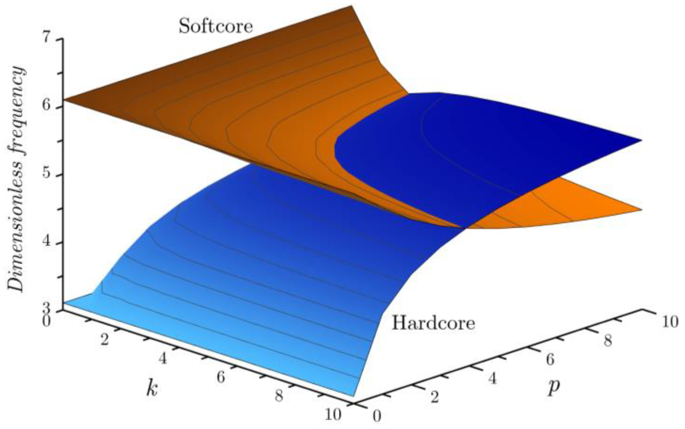
- When the inhomogeneity indexes , and increase, the hardcore FG shell becomes stiffer, while the softcore FG shell becomes less rigid.
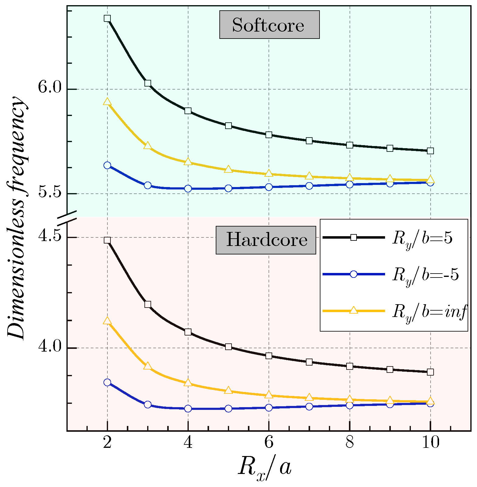
- For any FG structure scheme, increasing the aspect ratio and radius of curvature results in a decrease in dimensionless frequencies.
- Including porosities into the FG shell decreases its stiffness, causing a reduction in the frequencies.
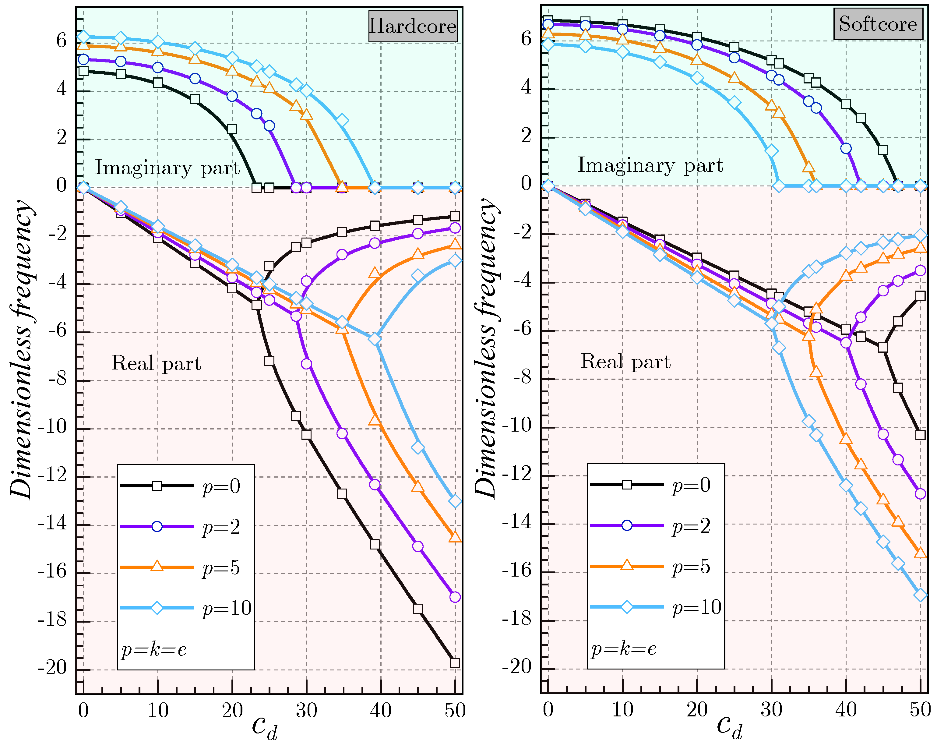
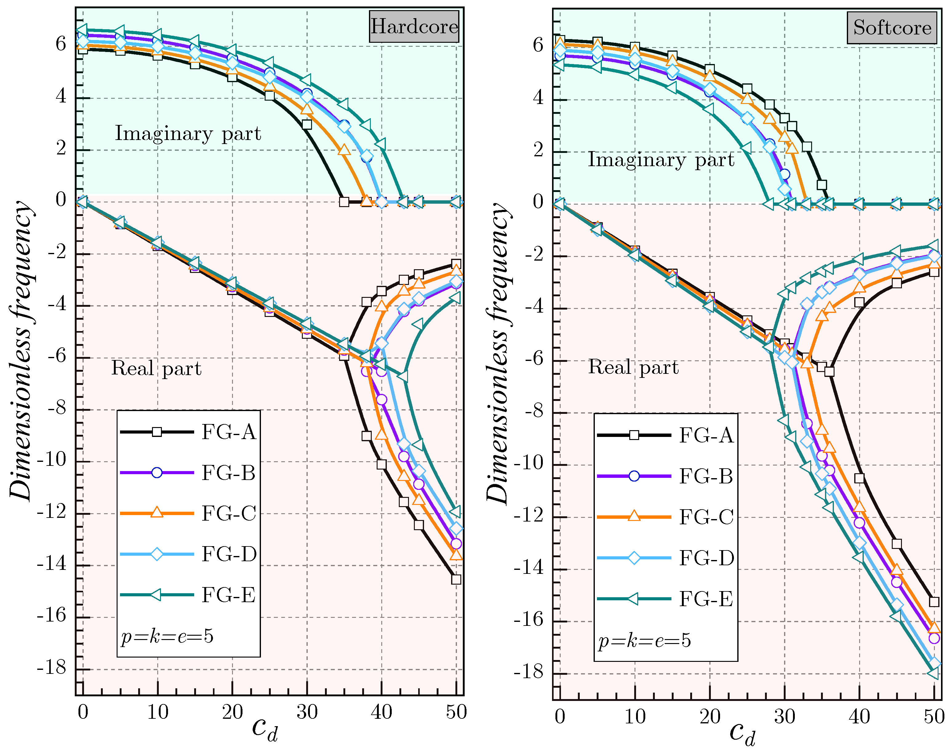
- The inclusion of the damping coefficient reduces the frequencies in a continuous manner, where the imaginary part of the eigenfrequency decreases as the damping coefficient increases.
- The inclusion of the Winkler/Pasternak foundations improves the rigidity of the shells, where the increase in various foundation parameters leads to an augmentation in the dimensionless frequency.
Author Contributions
Funding
Institutional Review Board Statement
Informed Consent Statement
Data Availability Statement
Conflicts of Interest
Appendix A
References
- Koizumi, M. FGM activities in Japan. Compos. Part B Eng. 1997, 28, 1–4. [Google Scholar] [CrossRef]
- Jha, D.; Kant, T.; Singh, R. A critical review of recent research on functionally graded plates. Compos. Struct. 2013, 96, 833–849. [Google Scholar] [CrossRef]
- Thanh, C.L.; Nguyen, T.N.; Vu, T.H.; Khatir, S.; Abdel Wahab, M. A geometrically nonlinear size-dependent hypothesis for porous functionally graded micro-plate. Eng. Comput. 2020, 38, 449–460. [Google Scholar] [CrossRef]
- Cuong-Le, T.; Nguyen, K.D.; Nguyen-Trong, N.; Khatir, S.; Nguyen-Xuan, H.; Abdel-Wahab, M. A three-dimensional solution for free vibration and buckling of annular plate, conical, cylinder and cylindrical shell of FG porous-cellular materials using IGA. Compos. Struct. 2021, 259, 113216. [Google Scholar] [CrossRef]
- Sahmani, S.; Fattahi, A.M.; Ahmed, N. Analytical treatment on the nonlocal strain gradient vibrational response of postbuckled functionally graded porous micro-/nanoplates reinforced with GPL. Eng. Comput. 2020, 36, 1559–1578. [Google Scholar] [CrossRef]
- Żur, K.K.; Arefi, M.; Kim, J.; Reddy, J.N. Free vibration and buckling analyses of magneto-electro-elastic FGM nanoplates based on nonlocal modified higher-order sinusoidal shear deformation theory. Compos. Part B Eng. 2020, 182, 107601. [Google Scholar] [CrossRef]
- Lü, C.; Lim, C.W.; Chen, W. Semi-analytical analysis for multi-directional functionally graded plates: 3-D elasticity solutions. Int. J. Numer. Methods Eng. 2009, 79, 25–44. [Google Scholar] [CrossRef]
- Nemat-Alla, M. Reduction of thermal stresses by composition optimization of two-dimensional functionally graded materials. Acta Mech. 2009, 208, 147–161. [Google Scholar] [CrossRef]
- Rad, A.B. Static analysis of two directional functionally graded circular plate under combined axisymmetric boundary conditions. Int. J. Eng. Appl. Sci. 2012, 4, 36–48. [Google Scholar]
- Behravan Rad, A.; Alibeigloo, A. Semi-Analytical Solution for the Static Analysis of 2D Functionally Graded Solid and Annular Circular Plates Resting on Elastic Foundation. Mech. Adv. Mater. Struct. 2013, 20, 515–528. [Google Scholar] [CrossRef]
- Nazari, H.; Babaei, M.; Kiarasi, F.; Asemi, K. Geometrically nonlinear dynamic analysis of functionally graded material plate excited by a moving load applying first-order shear deformation theory via generalized differential quadrature method. SN Appl. Sci. 2021, 3, 847. [Google Scholar] [CrossRef]
- Khakpour, M.; Bazargan-Lari, Y.; Zahedinejad, P.; Kazemzadeh-Parsi, M.-J. Vibrations evaluation of functionally graded porous beams in thermal surroundings by generalized differential quadrature method. Shock. Vib. 2022, 2022, 8516971. [Google Scholar] [CrossRef]
- Tornabene, F.; Fantuzzi, N.; Bacciocchi, M.; Viola, E.; Reddy, J.N. A numerical investigation on the natural frequencies of FGM sandwich shells with variable thickness by the local generalized differential quadrature method. Appl. Sci. 2017, 7, 131. [Google Scholar] [CrossRef]
- Shariyat, M.; Jafari, R. Nonlinear low-velocity impact response analysis of a radially preloaded two-directional-functionally graded circular plate: A refined contact stiffness approach. Compos. Part B Eng. 2013, 45, 981–994. [Google Scholar] [CrossRef]
- Adineh, M.; Kadkhodayan, M. Three-dimensional thermo-elastic analysis of multi-directional functionally graded rectangular plates on elastic foundation. Acta Mech. 2017, 228, 881–899. [Google Scholar] [CrossRef]
- Esmaeilzadeh, M.; Kadkhodayan, M. Dynamic analysis of stiffened bi-directional functionally graded plates with porosities under a moving load by dynamic relaxation method with kinetic damping. Aerosp. Sci. Technol. 2019, 93, 105333. [Google Scholar] [CrossRef]
- Alipour, M.; Shariyat, M.; Shaban, M. A semi-analytical solution for free vibration of variable thickness two-directional-functionally graded plates on elastic foundations. Int. J. Mech. Mater. Des. 2010, 6, 293–304. [Google Scholar] [CrossRef]
- Mikola, M.; Majak, J.; Pohlak, M.; Shvartsman, B. Higher order Haar wavelet method for vibration analysis of functionally graded beam. AIP Conf. Proc. 2022, 2425, 380003. [Google Scholar]
- Majak, J.; Shvartsman, B.; Ratas, M.; Bassir, D.; Pohlak, M.; Karjust, K.; Eerme, M. Higher-order Haar wavelet method for vibration analysis of nanobeams. Mater. Today Commun. 2020, 25, 101290. [Google Scholar] [CrossRef]
- Yas, M.; Moloudi, N. Three-dimensional free vibration analysis of multi-directional functionally graded piezoelectric annular plates on elastic foundations via state space based differential quadrature method. Appl. Math. Mech. 2015, 36, 439–464. [Google Scholar] [CrossRef]
- Lieu, Q.X.; Lee, S.; Kang, J.; Lee, J. Bending and free vibration analyses of in-plane bi-directional functionally graded plates with variable thickness using isogeometric analysis. Compos. Struct. 2018, 192, 434–451. [Google Scholar] [CrossRef]
- Lal, R.; Ahlawat, N. Buckling and vibrations of two-directional functionally graded circular plates subjected to hydrostatic in-plane force. J. Vib. Control. 2017, 23, 2111–2127. [Google Scholar] [CrossRef]
- Sorrenti, M.; Di Sciuva, M.; Majak, J.; Auriemma, F. Static response and buckling loads of multilayered composite beams using the refined zigzag theory and higher-order Haar wavelet method. Mech. Compos. Mater. 2021, 57, 1–18. [Google Scholar] [CrossRef]
- Majak, J.; Mikola, M.; Pohlak, M.; Eerme, M.; Karunanidhi, R. Modelling FGM materials. An accurate function approximation algorithms. IOP Conf. Ser. Mater. Sci. Eng. 2021, 1140, 012013. [Google Scholar] [CrossRef]
- Niknam, H.; Akbarzadeh, A.; Rodrigue, D.; Therriault, D. Architected multi-directional functionally graded cellular plates. Mater. Des. 2018, 148, 188–202. [Google Scholar] [CrossRef]
- Nguyen-Ngoc, H.; Cuong-Le, T.; Nguyen, K.D.; Nguyen-Xuan, H.; Abdel-Wahab, M. Three-dimensional polyhedral finite element method for the analysis of multi-directional functionally graded solid shells. Compos. Struct. 2023, 305, 116538. [Google Scholar] [CrossRef]
- Asgari, M.; Akhlaghi, M. Natural frequency analysis of 2D-FGM thick hollow cylinder based on three-dimensional elasticity equations. Eur. J. Mech.-A/Solids 2011, 30, 72–81. [Google Scholar] [CrossRef]
- Zafarmand, H.; Salehi, M.; Asemi, K. Three dimensional free vibration and transient analysis of two directional functionally graded thick cylindrical panels under impact loading. Lat. Am. J. Solids Struct. 2015, 12, 205–225. [Google Scholar] [CrossRef]
- Yamanouchi, M.; Koizumi, M.; Hirai, T.; Shiota, I. FGM’90. In Proceedings of the First International Symposium on Functionally Gradient Materials, Sendai, Japan, 8–9 October 1990. [Google Scholar]
- Shah, A.G.; Mahmood, T.; Naeem, M.N. Vibrations of FGM thin cylindrical shells with exponential volume fraction law. Appl. Math. Mech. 2009, 30, 607–615. [Google Scholar] [CrossRef]
- Chi, S.-H.; Chung, Y.-L. Mechanical behavior of functionally graded material plates under transverse load—Part I: Analysis. Int. J. Solids Struct. 2006, 43, 3657–3674. [Google Scholar] [CrossRef]
- Tornabene, F.; Viola, E. Free vibrations of four-parameter functionally graded parabolic panels and shells of revolution. Eur. J. Mech. A/Solids 2009, 28, 991–1013. [Google Scholar] [CrossRef]
- Ghamkhar, M.; Naeem, M.N.; Imran, M.; Soutis, C. Vibration analysis of a three-layered FGM cylindrical shell including the effect of ring support. Open Phys. 2019, 17, 587–600. [Google Scholar] [CrossRef]
- Pan, E. Exact solution for functionally graded anisotropic elastic composite laminates. J. Compos. Mater. 2003, 37, 1903–1920. [Google Scholar] [CrossRef]
- Daikh, A.-A.; Belarbi, M.-O.; Ahmed, D.; Houari, M.S.A.; Avcar, M.; Tounsi, A.; Eltaher, M.A. Static analysis of functionally graded plate structures resting on variable elastic foundation under various boundary conditions. Acta Mech. 2023, 234, 775–806. [Google Scholar] [CrossRef]
- Mourad, A.-H.I.; Almomani, A.; Sheikh, I.A.; Elsheikh, A.H. Failure analysis of gas and wind turbine blades: A review. Eng. Fail. Anal. 2023, 146, 107107. [Google Scholar] [CrossRef]
- Matsunaga, H. Free vibration and stability of functionally graded shallow shells according to a 2D higher-order deformation theory. Compos. Struct. 2008, 84, 132–146. [Google Scholar] [CrossRef]
- Lim, C.; Zhang, G.; Reddy, J. A higher-order nonlocal elasticity and strain gradient theory and its applications in wave propagation. J. Mech. Phys. Solids 2015, 78, 298–313. [Google Scholar] [CrossRef]
- Eringen, A.C. Plane waves in nonlocal micropolar elasticity. Int. J. Eng. Sci. 1984, 22, 1113–1121. [Google Scholar] [CrossRef]
- Daikh, A.A.; Houari, M.S.A.; Belarbi, M.O.; Mohamed, S.A.; Eltaher, M.A. Static and dynamic stability responses of multilayer functionally graded carbon nanotubes reinforced composite nanoplates via quasi 3D nonlocal strain gradient theory. Def. Technol. 2022, 18, 1778–1809. [Google Scholar] [CrossRef]
- Basha, M.; Daikh, A.A.; Melaibari, A.; Wagih, A.; Othman, R.; Almitani, K.H.; Hamed, M.A.; Abdelrahman, A.; Eltaher, M.A. Nonlocal strain gradient theory for buckling and bending of FG-GRNC laminated sandwich plates. Steel Compos. Struct. 2022, 43, 639–660. [Google Scholar]
- Ghandourah, E.E.; Daikh, A.A.; Alhawsawi, A.M.; Fallatah, O.A.; Eltaher, M.A. Bending and buckling of FG-GRNC laminated plates via quasi-3D nonlocal strain gradient theory. Mathematics 2022, 10, 1321. [Google Scholar] [CrossRef]
- Melaibari, A.; Daikh, A.A.; Basha, M.; Abdalla, A.W.; Othman, R.; Almitani, K.H.; Hamed, M.A.; Abdelrahman, A.; Eltaher, M.A. Free vibration of FG-CNTRCs nano-plates/shells with temperature-dependent properties. Mathematics 2022, 10, 583. [Google Scholar] [CrossRef]
- Alazwari, M.A.; Daikh, A.A.; Eltaher, M.A. Novel quasi 3D theory for mechanical responses of FG-CNTs reinforced composite nanoplates. Adv. Nano Res. 2022, 12, 117–137. [Google Scholar]
- Alijani, F.; Amabili, M.; Karagiozis, K.; Bakhtiari-Nejad, F. Nonlinear vibrations of functionally graded doubly curved shallow shells. J. Sound Vib. 2011, 330, 1432–1454. [Google Scholar] [CrossRef]
- Chorfi, S.; Houmat, A. Non-linear free vibration of a functionally graded doubly-curved shallow shell of elliptical plan-form. Compos. Struct. 2010, 92, 2573–2581. [Google Scholar] [CrossRef]
- Trinh, M.-C.; Kim, S.-E. A three variable refined shear deformation theory for porous functionally graded doubly curved shell analysis. Aerosp. Sci. Technol. 2019, 94, 105356. [Google Scholar] [CrossRef]


| Boundary Conditions | ||||
|---|---|---|---|---|
| SSSS | ||||
| CCCC | ||||
| CCSS | ||||
| Present | Ref. [45] | Error. (%) | Ref. [37] | Error. (%) | Ref. [46] | Error. (%) | Ref. [47] | Error. (%) | |||
|---|---|---|---|---|---|---|---|---|---|---|---|
| 0.5 | 0.5 | 0 | 0.0753 | 0.0779 | 0.08 | 0.0751 | 0.08 | 0.0762 | 0.08 | 0.0761 | 1.05 |
| 0.5 | 0.0653 | 0.0676 | 0.07 | 0.0657 | 0.07 | 0.0664 | 0.07 | 0.0662 | 1.36 | ||
| 1 | 0.0595 | 0.0617 | 0.06 | 0.0601 | 0.06 | 0.0607 | 0.06 | 0.0605 | 1.65 | ||
| 4 | 0.0496 | 0.0519 | 0.05 | 0.0503 | 0.05 | 0.0509 | 0.05 | 0.0506 | 1.98 | ||
| 10 | 0.0459 | 0.0482 | 0.05 | 0.0464 | 0.05 | 0.0471 | 0.05 | 0.0467 | 1.71 | ||
| 0.5 | 0 | 0 | 0.0622 | 0.0648 | 0.06 | 0.0622 | 0.06 | 0.0629 | 0.06 | 0.0628 | 0.96 |
| 0.5 | 0.0533 | 0.0553 | 0.06 | 0.0535 | 0.05 | 0.0540 | 0.05 | 0.0538 | 0.93 | ||
| 1 | 0.0482 | 0.0501 | 0.05 | 0.0485 | 0.05 | 0.0490 | 0.05 | 0.0488 | 1.23 | ||
| 4 | 0.0410 | 0.0430 | 0.04 | 0.0413 | 0.04 | 0.0419 | 0.04 | 0.0416 | 1.44 | ||
| 10 | 0.0387 | 0.0408 | 0.04 | 0.0390 | 0.04 | 0.0395 | 0.04 | 0.0392 | 1.28 | ||
| 0.5 | − 0.5 | 0 | 0.0563 | 0.0597 | 0.06 | 0.0563 | 0.06 | 0.0580 | 0.06 | 0.0577 | 2.43 |
| 0.5 | 0.0478 | 0.0506 | 0.05 | 0.0479 | 0.05 | 0.0493 | 0.05 | 0.0490 | 2.45 | ||
| 1 | 0.0431 | 0.0456 | 0.05 | 0.0432 | 0.04 | 0.0445 | 0.04 | 0.0442 | 2.49 | ||
| 4 | 0.0371 | 0.0396 | 0.04 | 0.0372 | 0.04 | 0.0385 | 0.04 | 0.0381 | 2.62 | ||
| 10 | 0.0354 | 0.0380 | 0.04 | 0.0355 | 0.04 | 0.0368 | 0.04 | 0.0364 | 2.75 |
| Hardcore | Softcore | |||||||||||
|---|---|---|---|---|---|---|---|---|---|---|---|---|
| FG-A | FG-B | FG-C | FG-D | FG-E | FG-A | FG-B | FG-C | FG-D | FG-E | |||
| 2 | 2 | 2 | 4.0055 | 4.9170 | 4.3295 | 4.7239 | 5.4687 | 5.8258 | 5.2103 | 5.6590 | 5.3289 | 4.5795 |
| 5 | 4.1749 | 5.2103 | 4.3295 | 4.7239 | 5.4687 | 5.7460 | 4.9170 | 5.6590 | 5.3289 | 4.5795 | ||
| 10 | 4.2468 | 5.3316 | 4.3295 | 4.7239 | 5.4687 | 5.7074 | 4.7697 | 5.6590 | 5.3289 | 4.5795 | ||
| 5 | 2 | 4.1749 | 5.2103 | 4.5382 | 4.7239 | 5.8052 | 5.7460 | 4.9170 | 5.5106 | 5.3289 | 3.9571 | |
| 5 | 4.3661 | 5.5287 | 4.5382 | 4.7239 | 5.8052 | 5.6359 | 4.4867 | 5.5106 | 5.3289 | 3.9571 | ||
| 10 | 4.4465 | 5.6590 | 4.5382 | 4.7239 | 5.8052 | 5.5812 | 4.2608 | 5.5106 | 5.3289 | 3.9571 | ||
| 10 | 2 | 4.2468 | 5.3316 | 4.6252 | 4.7239 | 5.9414 | 5.7074 | 4.7697 | 5.4334 | 5.3289 | 3.6077 | |
| 5 | 4.4465 | 5.6590 | 4.6252 | 4.7239 | 5.9414 | 5.5812 | 4.2608 | 5.4334 | 5.3289 | 3.6077 | ||
| 10 | 4.5300 | 5.7923 | 4.6252 | 4.7239 | 5.9414 | 5.5173 | 3.9864 | 5.4334 | 5.3289 | 3.6077 | ||
| 5 | 2 | 2 | 4.3796 | 4.9170 | 4.8036 | 5.3009 | 5.4687 | 5.6187 | 5.2103 | 5.3107 | 4.6802 | 4.5795 |
| 5 | 4.6032 | 5.2103 | 4.8036 | 5.3009 | 5.4687 | 5.4723 | 4.9170 | 5.3107 | 4.6802 | 4.5795 | ||
| 10 | 4.6969 | 5.3316 | 4.8036 | 5.3009 | 5.4687 | 5.4009 | 4.7697 | 5.3107 | 4.6802 | 4.5795 | ||
| 5 | 2 | 4.6032 | 5.2103 | 5.0692 | 5.3009 | 5.8052 | 5.4723 | 4.9170 | 5.0308 | 4.6802 | 3.9571 | |
| 5 | 4.8506 | 5.5287 | 5.0692 | 5.3009 | 5.8052 | 5.2675 | 4.4867 | 5.0308 | 4.6802 | 3.9571 | ||
| 10 | 4.9532 | 5.6590 | 5.0692 | 5.3009 | 5.8052 | 5.1645 | 4.2608 | 5.0308 | 4.6802 | 3.9571 | ||
| 10 | 2 | 4.6969 | 5.3316 | 5.1783 | 5.3009 | 5.9414 | 5.4009 | 4.7697 | 4.8832 | 4.6802 | 3.6077 | |
| 5 | 4.9532 | 5.6590 | 5.1783 | 5.3009 | 5.9414 | 5.1645 | 4.2608 | 4.8832 | 4.6802 | 3.6077 | ||
| 10 | 5.0590 | 5.7923 | 5.1783 | 5.3009 | 5.9414 | 5.0434 | 3.9864 | 4.8832 | 4.6802 | 3.6077 | ||
| 10 | 2 | 2 | 4.5963 | 4.9170 | 5.0737 | 5.6245 | 5.4687 | 5.4711 | 5.2103 | 5.0548 | 4.1843 | 4.5795 |
| 5 | 4.8489 | 5.2103 | 5.0737 | 5.6245 | 5.4687 | 5.2745 | 4.9170 | 5.0548 | 4.1843 | 4.5795 | ||
| 10 | 4.9542 | 5.3316 | 5.0737 | 5.6245 | 5.4687 | 5.1778 | 4.7697 | 5.0548 | 4.1843 | 4.5795 | ||
| 5 | 2 | 4.8489 | 5.2103 | 5.3690 | 5.6245 | 5.8052 | 5.2745 | 4.9170 | 4.6694 | 4.1843 | 3.9571 | |
| 5 | 5.1261 | 5.5287 | 5.3690 | 5.6245 | 5.8052 | 4.9957 | 4.4867 | 4.6694 | 4.1843 | 3.9571 | ||
| 10 | 5.2403 | 5.6590 | 5.3690 | 5.6245 | 5.8052 | 4.8542 | 4.2608 | 4.6694 | 4.1843 | 3.9571 | ||
| 10 | 2 | 4.9542 | 5.3316 | 5.4895 | 5.6245 | 5.9414 | 5.1778 | 4.7697 | 4.4647 | 4.1843 | 3.6077 | |
| 5 | 5.2403 | 5.6590 | 5.4895 | 5.6245 | 5.9414 | 4.8542 | 4.2608 | 4.4647 | 4.1843 | 3.6077 | ||
| 10 | 5.3577 | 5.7923 | 5.4895 | 5.6245 | 5.9414 | 4.6870 | 3.9864 | 4.4647 | 4.1843 | 3.6077 | ||
| Hardcore | Softcore | ||||||||||
|---|---|---|---|---|---|---|---|---|---|---|---|
| FG-A | FG-B | FG-C | FG-D | FG-E | FG-A | FG-B | FG-C | FG-D | FG-E | ||
| 5. 5 | 2 | 4.0055 | 4.9170 | 4.3295 | 4.7239 | 5.4687 | 5.8258 | 5.2103 | 5.6590 | 5.3289 | 4.5795 |
| 5 | 4.8506 | 5.5287 | 5.0692 | 5.3009 | 5.8052 | 5.2675 | 4.4867 | 5.0308 | 4.6802 | 3.9571 | |
| 10 | 5.3577 | 5.7923 | 5.4895 | 5.6245 | 5.9414 | 4.6870 | 3.9864 | 4.4647 | 4.1843 | 3.6077 | |
| 5. -5 | 2 | 3.7255 | 4.6385 | 4.0137 | 4.3656 | 5.1589 | 5.5258 | 4.9151 | 5.3862 | 5.1039 | 4.3201 |
| 5 | 4.5271 | 5.2155 | 4.7281 | 4.9411 | 5.4762 | 5.0135 | 4.2326 | 4.8028 | 4.4887 | 3.7331 | |
| 10 | 5.0209 | 5.4641 | 5.1436 | 5.2692 | 5.6047 | 4.4643 | 3.7608 | 4.2620 | 4.0067 | 3.4036 | |
| 5. inf | 2 | 3.8048 | 4.7190 | 4.1029 | 4.4665 | 5.2485 | 5.6136 | 5.0005 | 5.4666 | 5.1716 | 4.3951 |
| 5 | 4.6192 | 5.3061 | 4.8251 | 5.0434 | 5.5714 | 5.0884 | 4.3061 | 4.8706 | 4.5466 | 3.7979 | |
| 10 | 5.1173 | 5.5590 | 5.2426 | 5.3708 | 5.7021 | 4.5301 | 3.8260 | 4.3223 | 4.0601 | 3.4627 | |
| Type of Porosity | Hardcore | Softcore | |||||||||
|---|---|---|---|---|---|---|---|---|---|---|---|
| FG-A | FG-B | FG-C | FG-D | FG-E | FG-A | FG-B | FG-C | FG-D | FG-E | ||
| I | 0.1 | 3.8451 | 4.7723 | 4.1594 | 4.5901 | 5.3592 | 5.7250 | 5.0323 | 5.5359 | 5.1857 | 4.4096 |
| 0.2 | 3.6982 | 4.5961 | 4.0124 | 4.4722 | 5.2499 | 5.5962 | 4.8241 | 5.3896 | 5.0288 | 4.2263 | |
| II | 0.1 | 3.9311 | 4.8628 | 4.2688 | 4.6916 | 5.4132 | 5.7919 | 5.1247 | 5.6201 | 5.2854 | 4.4961 |
| 0.2 | 3.8589 | 4.7675 | 4.2079 | 4.6587 | 5.3563 | 5.7542 | 5.0323 | 5.5775 | 5.2373 | 4.4096 | |
| III | 0.1 | 3.9207 | 4.8310 | 4.2407 | 4.6703 | 5.3944 | 5.7762 | 5.0947 | 5.6011 | 5.2637 | 4.4676 |
| 0.2 | 3.8215 | 4.7039 | 4.1521 | 4.6150 | 5.3174 | 5.7187 | 4.9666 | 5.5361 | 5.1907 | 4.3501 | |
| IV | 0.1 | 3.9446 | 4.8990 | 4.2469 | 4.6451 | 5.4346 | 5.7808 | 5.1539 | 5.5989 | 5.2524 | 4.5242 |
| 0.2 | 3.8825 | 4.8486 | 4.1826 | 4.5842 | 5.4049 | 5.7315 | 5.0947 | 5.5349 | 5.1738 | 4.4676 | |
| Hardcore | Softcore | ||||||||||
|---|---|---|---|---|---|---|---|---|---|---|---|
| FG-A | FG-B | FG-C | FG-D | FG-E | FG-A | FG-B | FG-C | FG-D | FG-E | ||
| 0 | 0 | 4.0055 | 4.9170 | 4.3295 | 4.7239 | 5.4687 | 5.8258 | 5.2103 | 5.6590 | 5.3289 | 4.5795 |
| 0.5 | 4.2163 | 5.1720 | 4.5582 | 4.9744 | 5.7524 | 6.1262 | 5.4805 | 5.9496 | 5.6006 | 4.8169 | |
| 1 | 4.4105 | 5.4084 | 4.7686 | 5.2044 | 6.0155 | 6.4054 | 5.7311 | 6.2202 | 5.8543 | 5.0370 | |
| 1.5 | 4.5915 | 5.6300 | 4.9645 | 5.4184 | 6.2620 | 6.6677 | 5.9659 | 6.4748 | 6.0935 | 5.2434 | |
| 2 | 4.7620 | 5.8395 | 5.1488 | 5.6195 | 6.4951 | 6.9161 | 6.1880 | 6.7160 | 6.3207 | 5.4384 | |
| 0.5 | 0 | 3.8217 | 4.6912 | 4.1308 | 4.5070 | 5.2176 | 5.5582 | 4.9710 | 5.3991 | 5.0842 | 4.3693 |
| 0.5 | 4.0228 | 4.9345 | 4.3490 | 4.7460 | 5.4882 | 5.8448 | 5.2288 | 5.6763 | 5.3434 | 4.5958 | |
| 1 | 4.2081 | 5.1600 | 4.5497 | 4.9654 | 5.7392 | 6.1112 | 5.4679 | 5.9345 | 5.5854 | 4.8058 | |
| 1.5 | 4.3808 | 5.3714 | 4.7366 | 5.1696 | 5.9744 | 6.3614 | 5.6919 | 6.1773 | 5.8137 | 5.0026 | |
| 2 | 4.5434 | 5.5713 | 4.9124 | 5.3614 | 6.1967 | 6.5983 | 5.9037 | 6.4075 | 6.0304 | 5.1887 | |
| 1 | 0 | 3.6612 | 4.4940 | 3.9572 | 4.3175 | 4.9981 | 5.3244 | 4.7620 | 5.1720 | 4.8704 | 4.1856 |
| 0.5 | 3.8538 | 4.7270 | 4.1662 | 4.5464 | 5.2574 | 5.5989 | 5.0089 | 5.4376 | 5.1187 | 4.4026 | |
| 1 | 4.0312 | 4.9430 | 4.3584 | 4.7566 | 5.4977 | 5.8541 | 5.2379 | 5.6849 | 5.3505 | 4.6037 | |
| 1.5 | 4.1967 | 5.1455 | 4.5375 | 4.9522 | 5.7230 | 6.0938 | 5.4525 | 5.9175 | 5.5691 | 4.7923 | |
| 2 | 4.3524 | 5.3370 | 4.7058 | 5.1359 | 5.9360 | 6.3207 | 5.6554 | 6.1379 | 5.7767 | 4.9705 | |
| 1.5 | 0 | 3.5194 | 4.3198 | 3.8038 | 4.1501 | 4.8043 | 5.1179 | 4.5773 | 4.9714 | 4.6816 | 4.0234 |
| 0.5 | 3.7045 | 4.5437 | 4.0047 | 4.3701 | 5.0535 | 5.3817 | 4.8147 | 5.2267 | 4.9202 | 4.2319 | |
| 1 | 3.8750 | 4.7514 | 4.1895 | 4.5722 | 5.2845 | 5.6270 | 5.0347 | 5.4644 | 5.1430 | 4.4253 | |
| 1.5 | 4.0340 | 4.9460 | 4.3615 | 4.7601 | 5.5010 | 5.8574 | 5.2410 | 5.6879 | 5.3531 | 4.6065 | |
| 2 | 4.1837 | 5.1300 | 4.5234 | 4.9367 | 5.7057 | 6.0755 | 5.4360 | 5.8998 | 5.5527 | 4.7778 | |
| 2 | 0 | 3.3929 | 4.1644 | 3.6671 | 4.0008 | 4.6314 | 4.9337 | 4.4126 | 4.7925 | 4.5132 | 3.8787 |
| 0.5 | 3.5714 | 4.3803 | 3.8607 | 4.2129 | 4.8716 | 5.1880 | 4.6414 | 5.0386 | 4.7431 | 4.0797 | |
| 1 | 3.7357 | 4.5804 | 4.0388 | 4.4077 | 5.0943 | 5.4244 | 4.8536 | 5.2677 | 4.9579 | 4.2661 | |
| 1.5 | 3.8890 | 4.7680 | 4.2047 | 4.5888 | 5.3030 | 5.6465 | 5.0524 | 5.4832 | 5.1605 | 4.4408 | |
| 2 | 4.0333 | 4.9453 | 4.3607 | 4.7591 | 5.5003 | 5.8568 | 5.2403 | 5.6874 | 5.3528 | 4.6059 | |
| Hardcore | Softcore | ||||||||||
|---|---|---|---|---|---|---|---|---|---|---|---|
| FG-A | FG-B | FG-C | FG-D | FG-E | FG-A | FG-B | FG-C | FG-D | FG-E | ||
| SSSS | 0.5 | 9.1619 | 11.2542 | 9.8934 | 10.7837 | 12.5161 | 13.2973 | 11.9250 | 12.8725 | 11.9495 | 10.4823 |
| 1 | 4.0055 | 4.9170 | 4.3295 | 4.7239 | 5.4687 | 5.8258 | 5.2103 | 5.6590 | 5.3289 | 4.5795 | |
| 2 | 2.5101 | 3.0935 | 2.7117 | 2.9573 | 3.4410 | 3.6743 | 3.2782 | 3.5761 | 3.3879 | 2.8809 | |
| 3 | 2.1746 | 2.6964 | 2.3463 | 2.5557 | 2.9994 | 3.2109 | 2.8575 | 3.1304 | 2.9765 | 2.5111 | |
| CCCC | 0.5 | 17.1757 | 20.5725 | 18.6212 | 20.3661 | 22.8825 | 23.9064 | 21.8004 | 22.8049 | 20.2667 | 19.1594 |
| 1 | 7.1130 | 8.6916 | 7.6910 | 8.3931 | 9.6678 | 10.2469 | 9.2105 | 9.9013 | 9.1508 | 8.0944 | |
| 2 | 4.9556 | 6.0692 | 5.3577 | 5.8464 | 6.7512 | 7.1709 | 6.4317 | 6.9435 | 6.4631 | 5.6520 | |
| 3 | 4.6526 | 5.7008 | 5.0296 | 5.4878 | 6.3415 | 6.7371 | 6.0414 | 6.5243 | 6.0743 | 5.3089 | |
| CSCS | 0.5 | 16.1992 | 19.6201 | 17.5320 | 19.1469 | 21.8226 | 22.9562 | 20.7909 | 22.0272 | 19.9015 | 18.2729 |
| 1 | 6.8300 | 8.3911 | 7.3782 | 8.0451 | 9.3334 | 9.9241 | 8.8920 | 9.6157 | 8.9589 | 7.8147 | |
| 2 | 4.5431 | 5.5965 | 4.9068 | 5.3495 | 6.2253 | 6.6350 | 5.9308 | 6.4431 | 6.0494 | 5.2118 | |
| 3 | 4.1493 | 5.1173 | 4.4806 | 4.8840 | 5.6924 | 6.0707 | 5.4230 | 5.8980 | 5.5450 | 4.7655 | |
| Hardcore | Softcore | |||||||||||
|---|---|---|---|---|---|---|---|---|---|---|---|---|
| FG-A | FG-B | FG-C | FG-D | FG-E | FG-A | FG-B | FG-C | FG-D | FG-E | |||
| 0 | 0 | 0 | 4.0055 | 4.9170 | 4.3295 | 4.7239 | 5.4687 | 5.8258 | 5.2103 | 5.6590 | 5.3289 | 4.5795 |
| 50 | 8.4668 | 8.7744 | 8.4604 | 8.4517 | 8.8876 | 9.0797 | 8.8333 | 9.1046 | 9.1277 | 8.7104 | ||
| 100 | 11.2829 | 11.3923 | 11.1533 | 10.9789 | 11.3163 | 11.4424 | 11.3530 | 11.5649 | 11.7561 | 11.4345 | ||
| 50 | 0 | 4.6565 | 5.4340 | 4.9090 | 5.2242 | 5.9060 | 6.2333 | 5.6835 | 6.0974 | 5.8277 | 5.1512 | |
| 50 | 8.7934 | 9.0742 | 8.7710 | 8.7411 | 9.1630 | 9.3463 | 9.1204 | 9.3833 | 9.4275 | 9.0240 | ||
| 100 | 11.5299 | 11.6247 | 11.3906 | 11.2031 | 11.5338 | 11.6551 | 11.5777 | 11.7855 | 11.9903 | 11.6751 | ||
| 100 | 0 | 5.2270 | 5.9059 | 5.4270 | 5.6806 | 6.3130 | 6.6158 | 6.1203 | 6.5064 | 6.2871 | 5.6655 | |
| 50 | 9.1082 | 9.3643 | 9.0710 | 9.0212 | 9.4305 | 9.6056 | 9.3987 | 9.6540 | 9.7180 | 9.3271 | ||
| 100 | 11.7717 | 11.8525 | 11.6231 | 11.4230 | 11.7474 | 11.8639 | 11.7982 | 12.0021 | 12.2199 | 11.9107 | ||
| 10 | 0 | 2 | 3.5457 | 4.5879 | 3.9515 | 4.4283 | 5.216 | 5.5949 | 4.9239 | 5.3966 | 5.0016 | 4.1943 |
| 5 | 8.2596 | 8.5946 | 8.2736 | 8.2903 | 8.7345 | 8.9334 | 8.6676 | 8.9440 | 8.9409 | 8.5146 | ||
| 10 | 11.1290 | 11.255 | 11.0120 | 10.8550 | 11.1970 | 11.3270 | 11.2250 | 11.4390 | 11.6120 | 11.2860 | ||
| 50 | 2 | 4.2675 | 5.1382 | 4.5792 | 4.9586 | 5.6728 | 6.0181 | 5.4222 | 5.8548 | 5.5301 | 4.8121 | |
| 5 | 8.5941 | 8.9004 | 8.5910 | 8.5852 | 9.0146 | 9.2043 | 8.9600 | 9.2276 | 9.2468 | 8.8351 | ||
| 10 | 11.3790 | 11.4900 | 11.2530 | 11.0820 | 11.4160 | 11.5420 | 11.4520 | 11.6620 | 11.8490 | 11.5300 | ||
| 100 | 2 | 4.8837 | 5.6350 | 5.1306 | 5.4373 | 6.0954 | 6.4135 | 5.8785 | 6.2796 | 6.0123 | 5.3591 | |
| 5 | 8.9160 | 9.1961 | 8.8971 | 8.8703 | 9.2864 | 9.4675 | 9.2432 | 9.5028 | 9.5429 | 9.1445 | ||
| 10 | 11.6240 | 11.7200 | 11.488 | 11.3040 | 11.6320 | 11.7530 | 11.6750 | 11.8810 | 12.0810 | 11.7690 | ||
| 20 | 0 | 2 | 1.467 | 3.4153 | 2.4944 | 3.3904 | 4.3707 | 4.8364 | 3.9415 | 4.5186 | 3.8558 | 2.7294 |
| 5 | 7.6038 | 8.0309 | 7.6858 | 7.7860 | 8.2580 | 8.4795 | 8.1504 | 8.4440 | 8.3552 | 7.8975 | ||
| 10 | 10.652 | 10.8310 | 10.5790 | 10.4760 | 10.8290 | 10.9730 | 10.8310 | 11.0530 | 11.1680 | 10.8290 | ||
| 50 | 2 | 2.7916 | 4.1253 | 3.4026 | 4.0586 | 4.9069 | 5.3203 | 4.5489 | 5.0571 | 4.5205 | 3.6076 | |
| 5 | 7.966 | 8.3574 | 8.0266 | 8.0993 | 8.5539 | 8.7645 | 8.4607 | 8.7439 | 8.6819 | 8.2423 | ||
| 10 | 10.913 | 11.075 | 10.829 | 10.71 | 11.0570 | 11.194 | 11.066 | 11.284 | 11.4150 | 11.0830 | ||
| 100 | 2 | 3.6652 | 4.7298 | 4.1149 | 4.6315 | 5.3900 | 5.7638 | 5.0843 | 5.5435 | 5.0993 | 4.3105 | |
| 5 | 8.3124 | 8.6717 | 8.3534 | 8.4009 | 8.8398 | 9.0405 | 8.7601 | 9.0339 | 8.9967 | 8.5731 | ||
| 10 | 11.169 | 11.3140 | 11.0730 | 10.9400 | 11.279 | 11.4120 | 11.2970 | 11.5100 | 11.6560 | 11.3310 | ||
Disclaimer/Publisher’s Note: The statements, opinions and data contained in all publications are solely those of the individual author(s) and contributor(s) and not of MDPI and/or the editor(s). MDPI and/or the editor(s) disclaim responsibility for any injury to people or property resulting from any ideas, methods, instructions or products referred to in the content. |
© 2023 by the authors. Licensee MDPI, Basel, Switzerland. This article is an open access article distributed under the terms and conditions of the Creative Commons Attribution (CC BY) license (https://creativecommons.org/licenses/by/4.0/).
Share and Cite
Ghandourah, E.E.; Daikh, A.A.; Khatir, S.; Alhawsawi, A.M.; Banoqitah, E.M.; Eltaher, M.A. A Dynamic Analysis of Porous Coated Functionally Graded Nanoshells Rested on Viscoelastic Medium. Mathematics 2023, 11, 2407. https://doi.org/10.3390/math11102407
Ghandourah EE, Daikh AA, Khatir S, Alhawsawi AM, Banoqitah EM, Eltaher MA. A Dynamic Analysis of Porous Coated Functionally Graded Nanoshells Rested on Viscoelastic Medium. Mathematics. 2023; 11(10):2407. https://doi.org/10.3390/math11102407
Chicago/Turabian StyleGhandourah, Emad E., Ahmed Amine Daikh, Samir Khatir, Abdulsalam M. Alhawsawi, Essam M. Banoqitah, and Mohamed A. Eltaher. 2023. "A Dynamic Analysis of Porous Coated Functionally Graded Nanoshells Rested on Viscoelastic Medium" Mathematics 11, no. 10: 2407. https://doi.org/10.3390/math11102407
APA StyleGhandourah, E. E., Daikh, A. A., Khatir, S., Alhawsawi, A. M., Banoqitah, E. M., & Eltaher, M. A. (2023). A Dynamic Analysis of Porous Coated Functionally Graded Nanoshells Rested on Viscoelastic Medium. Mathematics, 11(10), 2407. https://doi.org/10.3390/math11102407