Article

The Influence of GPL Reinforcements on the Post-Buckling Behavior of FG Porous Rings Subjected to an External Pressure

1
Quzhou College of Technology, Quzhou 324000, China
2
Department of Mechanical Engineering, University of Eyvanekey, Eyvanekey 99888-35918, Iran
3
Department of Innovation Engineering, Faculty of Engineering, University of Salento, 73100 Lecce, Italy
*
Authors to whom correspondence should be addressed.
Mathematics 2023, 11(11), 2421; https://doi.org/10.3390/math11112421
Submission received: 1 May 2023 / Revised: 20 May 2023 / Accepted: 22 May 2023 / Published: 23 May 2023
(This article belongs to the Special Issue Advances in Computational Solid Mechanics and Scientific Computing)

Abstract

:
The work focuses on the post- buckling behavior of functionally graded graphene platelet (FG-GPL)-reinforced porous thick rings with open-cell internal cavities under a uniform external pressure. The generalized rule of mixture and the modified Halpin–Tsai model are here used to evaluate the effective mechanical properties of the ring. Three types of porosity patterns are assumed together with five different GPL distributions as reinforcement across the ring thickness. The theoretical formulation relies on a 2D-plane stress linear elasticity theory and Green strain field in conjunction a virtual work principle to derive the nonlinear governing equations of the post-buckling problem. Unlike the simple ring models, 2D elasticity considers the thickness stretching. The finite element model combined with an iterative Newton–Raphson algorithm is used to obtain the post-buckling path of the ring up to the collapse. A systematic investigation evaluates the effect of the weight fraction of nanofillers, the coefficient of porosity, porosity distribution, and the GPLs distribution on the deep post-buckling path of the ring. Based on the results, it is found that the buckling value and post-buckling strength increase considerably (by approximately 80%) by increasing the weight fraction of the nanofiller of about 1%.

1. Introduction

Rings are considered as a major solid structure largely used as reinforcement for closed shell-like constructions and offshore pipelines. In many applications, rings are usually subjected to a compression loading undergoing buckling phenomena. An adequate knowledge of the post-buckling behavior will be useful to designers to calculate the remaining capacity of such structures. Many investigations have been reported in the literature about the buckling and post-buckling behavior of rings. For instance, Wah [1] presented a simple model for evaluating the in-plane buckling of rings subjected to uniform compressive load. Hazel and Mullin [2] performed a double computational and experimental investigation on the elastic buckling response of rings under an external confinement, while using a Kirchhoff–Love beam theory. Azzuni and Guzey [3] presented an analytical solution based on a perturbation approach for the post-buckling analysis of rings under non-uniform double symmetric loads. The elastic buckling of rings subjected to a uniform external pressure was also analyzed by Seide and Weingarten [4]. Azzuni and Guzey [5] applied an analytical study for the deflection and buckling behavior of rings with large deflections. Kerdegarbakhsh et al. [6] employed the first order shear deformation theory (FSDT) to analyse the post-buckling behavior of FGM rings, whose solution was found numerically based on a generalized differential quadrature method (GDQM). Lagrange et al. [7] investigated analytically and numerically the buckling response of a ring resting on an annular elastic foundation. Thurston [8] also studied the impact of the loading type on the post-buckling response of a ring. Thurston employed the general Newton procedure to derive the buckling pressures and post-buckling paths of the closed rings. Sills and Budiansky [9] stated that differently from rings under pure hydrostatic, constant radial, and directional forces, rings are commonly exposed to inverse-square radial loads with a nonlinear bending behavior. Asemi and Kiani [10] employed a 2D elasticity theory to investigate the post-buckling behavior of orthotropic rings by means of the finite element approach. Zhang et al. [11] applied a classical shell theory and proposed an analytical solution for the stability problem of submarine bi-material pipeline-liner systems constructed of novel polyhedral composites under a thermo–mechanical loading.
At the same time, porous cellular constructions with great properties, including lightweight, heat resistance, and great energy absorption, have been extensively applied in different systems [12,13,14,15,16]. In addition, Mousavi et al. [17] proposed an analytical formulation based on a trigonometric theory to describe the initial curvature influences on the free vibration response of porous micro beams combined with FG piezoelectric layers. Bouhadra, Menasria, and Rachedi [18] investigated the effect edge conditions for the buckling behavior of porous FG nanobeams based on a quasi-2D and 3D formulation. Keleshteri and Jelovica [19] studied the nonlinear vibration analysis of bidirectional porous beams based on a Reddy beam theory, while employing the GDQM. A refined third-order theory was also proposed by Beg et al. [20] for the study of the static and free vibration response of functionally graded porous curved beams. Akbaş [21] investigated the dynamics of axially FG porous beams subjected to a moving force, as provided by the FSDT beam theory and Ritz procedure. Huang and Tahouneh [22] performed an investigation about the natural frequencies of FG porous material beam on a two-parameter elastic medium according to a Timoshenko theory and differential quadrature approach. Madenci and Ozkili [23] performed a comprehensive investigation, including the analytical and numerical approaches for natural frequencies of open-cell FG porous beams. Rahmani and Mohammadi [24] studied the vibration behavior of FG porous conical shells for different boundary conditions by employing a high-order shell theory and Galerkin method to solve the problem. The wave propagation of porous FG curved beams in thermal conditions was also presented by Xu et al. [25], whereas Farrokh and Taheripur [26] studied the optimization topology of FG porous beams under a buckling load based on the Euler and Timoshenko beam theories. Yuksel and Akbas [27] presented an analytical solution for the hygrothermal stress analysis of laminated composite porous plates based on the FSDT. Moreover, Chen et al. [28] proposed a nonlocal strain gradient finite element method to assess the nonlinear response of FGM porous microplates with a central cutout. The natural frequencies of porous magneto–electro–elastically actuated CNT-reinforced composite sandwich plates was presented by Ebrahimi et al. [29] by employing a refined plate theory.
However, Xia et al. [30] and Jena and Malikan [31] stated that the structural stiffness decreases considerably due to the internal cavities in the matrix. To overcome this drawback, different nanofillers, e.g., CNTs or GPLs, were immersed in the matrix phase [32,33,34,35,36] as a useful method to enhance their properties. To enhance the potential properties of the structures, FG porous constructions reinforced by GPLs were introduced by Hassani et al. [37] and Dong et al. [38]. Different investigations have been conducted to study the effect of porosity and GPLs distributions on these structures.
In the following, we report some further key works related to the buckling and post-buckling response of such structures. More specifically, a FSDT and Rayleigh–Ritz method was applied in Refs. [39,40], to analyze the buckling [39] and torsional buckling [40] of FG-GPL porous cylindrical shells. Dong et al. [41] also employed a FSDT for an analytical investigation of the buckling response of FG-GPL porous cylindrical shells. A further analytical treatment of the nonlinear vibration and post-buckling problems based on a Ritz method was proposed by Chen et al. [42] focusing on FG-GPLs porous nanocomposite beams as useful for design purposes of many engineering nanodevices. Kitipornchai et al. [43] investigated the free vibration and buckling responses of FG porous beams reinforced by GPLs. Similarly, Yang et al. [44] studied the buckling load of FG-GPL porous plates based on the FSDT, while proposing the Chebyshev–Ritz method as a valid analytical solution. A classical shell theory and higher-order shear deformation theory (HSDT) were used by Zhou et al. [45] to determine the nonlinear buckling response of FG-GPL porous cylindrical shells, whereas the same method was implemented in [46] for the buckling and post-buckling analyses of FG-GPL porous plates with different shapes and edge conditions. In addition, a closed-form solution was proposed by Yaghoobi and Taheri [47] to investigate the buckling behavior of sandwich plates with a FG-GPL porous core, with an extension of the solution in [48] to the post-buckling response of sandwich cylindrical shell panels with a FG-GPL porous core. An advanced isogeometric approach was, instead, proposed by Nguyen et al. [49] to treat an affine buckling problem of FG-GPL porous plates. Priyanka et al. [50] considered the effect of different porosities and GPL patterns on the natural frequencies and buckling forces of FG-GPL porous cylindrical panels always resorting to the HSDT. Barati and Zenkour [51] applied a Euler theory to capture the post-buckling paths of FG-GPL porous beams by employing a Galerkin solution. Li et al. [52] evaluated the buckling performance of FG porous composite pipelines with various shapes reinforced by GPLs under an external pressure. Similarly, Xiao et al. [53] proposed an analytical model for the nonlinear buckling response of a confined polyhedral FG porous-GPLs lining subjected to a point loading, whereas in Ref. [54], the same authors applied the nonlinear thin-walled shell theory and principle of minimum potential energy to investigate the nonlinear in-plane instability of confined FGP arches with nanocomposites reinforcements under a radial uniform pressure.
According to the most important literature overview mentioned above, it is worth noting that the post-buckling of rings constructed of FG porous material reinforced by GPLs has not been surveyed, so far. Due to the common presence of buckling loading conditions in most ring structures in many industries, large attention must be devoted by researchers and designers to the knowledge of critical conditions and structural capacity, especially in post-buckling situations. In such a context, this work focuses on the post- buckling response of FG porous rings reinforced by GPLs according to a 2D elasticity theory in lieu of simple shell theories. The proposed theory considers the thickness stretching effects and predicts the post-buckling behavior accurately, involving the nonlinear Green strain field rather than a Von Kármán nonlinearity. An FEM-based approach is combined to a Newton–Raphson iterative scheme to derive the post-buckling paths of FG-GPL porous rings. A systematic study is here performed to evaluate the effect of various porosity distributions and GPL patterns, porosity coefficients, and weight fractions of the nanofiller on the post-buckling response of FG porous thick closed rings, whose results could serve for design purposes of such structural components.

2. Theoretical Formulation

2.1. Description of the Geometry

Let us consider a closed circular ring in polar coordinates, as shown in Figure 1, in which h , R , rout, and rin are thickness, mean radius, and outer and inner radii of the ring, respectively.

2.2. Obtaining the Effective Mechanical Properties of the Ring

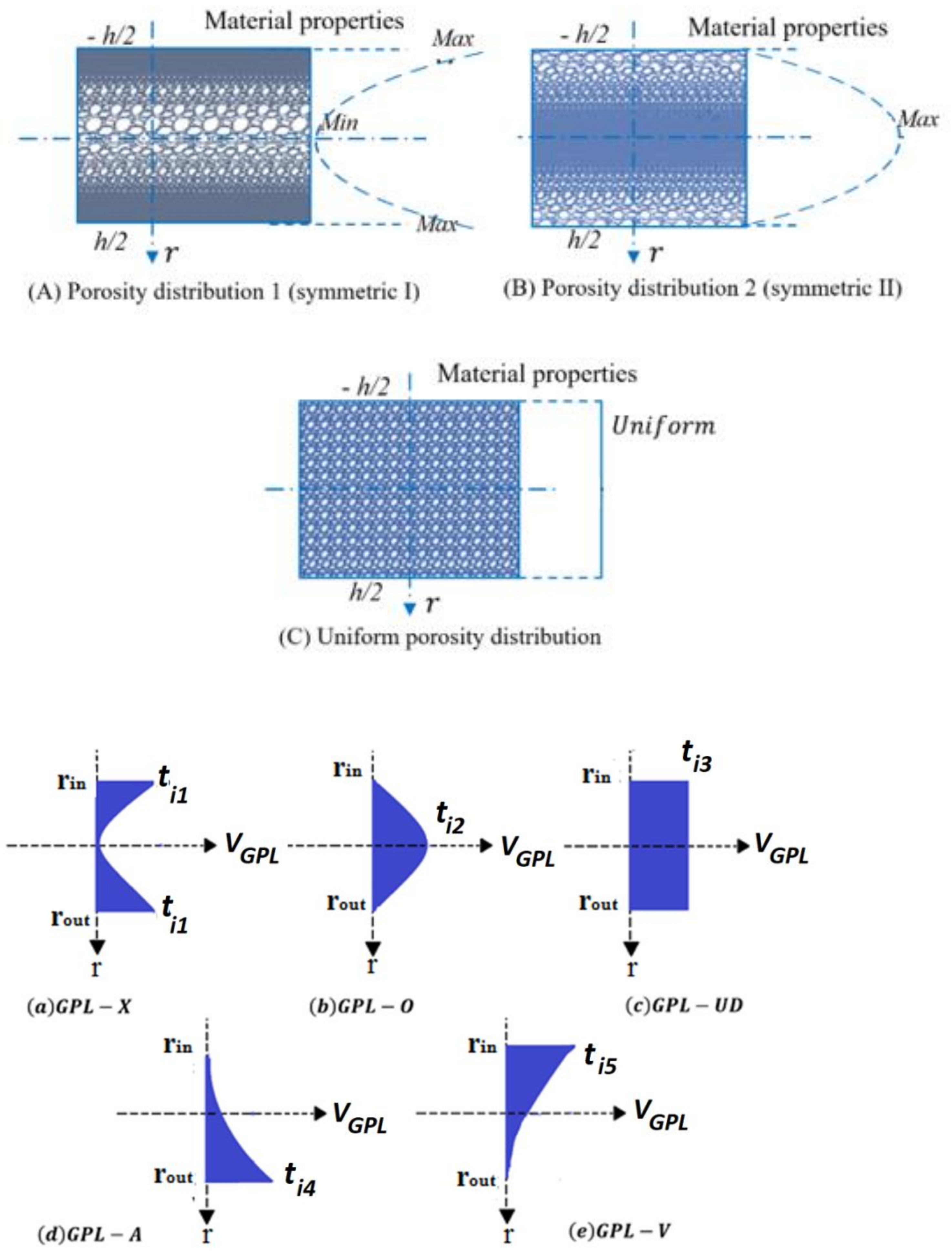
Three various porosity patterns are considered across the ring thickness (Figure 2), as described hereafter, together with five GPL dispersion patterns across the thickness of ring [55,56,57]. More follows in detail hereafter, and we will describe the elasticity modulus E r , shear modulus G r , and mass density ρ r of porous nanocomposite ring according to Ref. [58].
Porosity distribution 1 (non-uniform symmetric I-PD1):
E r = E * 1 e 0 cos π ( r r i n h 1 2 ) G r = G * 1 e 0 cos π ( r r i n h 1 2 ) ρ r = ρ * 1 e m cos π ( r r i n h 1 2 )
Porosity distribution 2 (non-uniform symmetric II-PD2):
E r = E * 1 e 0 * ( 1 cos π ( r r i n h 1 2 ) G r = G * 1 e 0 * ( 1 cos π ( r r i n h 1 2 ) ρ r = ρ * 1 e m * ( 1 cos π ( r r i n h 1 2 )
Porosity distribution 3 (PD3):
E = E * α G = G * α ρ = ρ * α
where E * ,   G * , and ρ * refer to the elasticity modulus, shear modulus, and mass density of the GPL ring without internal pores, respectively. Also, e 0 and e 0 *   ( 0 e 0 e 0 * < 1 ) represent the porosity coefficients for pattern 1 and 2, respectively. Note also that the porosity coefficient for the third distribution is labeled as α , whereas e m and e m *   refer to the mass density coefficient for distributions 1 and 2, respectively. Also, the mass density coefficient for distribution 3 is presented by the α symbol.
The Young’s modulus and density for open-cell metal foams are related as [59,60,61].
E r E * = ρ r ρ * 2
whose equation is applied to estimate the relation between the porosity coefficients and mass density coefficients for different porosity distributions, as follows:
1 e m cos π r = 1 e 0 cos π r 1 e m * cos π r = 1 e 0 * cos π r α = α              
It is supposed that the mass of various rings with different distributions of porosity and GPL dispersion patterns are the same.
r i n r o u t 1 e 0 cos π r d r = r i n r o u t 1 e 0 * 1 cos π r d r = 0 h / 2 α d r
Based on Equation (6), the amounts of e 0 * and α   may be evaluated with a known value of e 0 , as given in Table 1. By increasing   e 0 , the amounts of e 0 * increase while α decrease. When e 0 reaches 0.6, e 0 *   becomes equal to 0.9612. Thus, e 0   [0, 0.6] is used in this work.
The Young’s modulus of the nanocomposite without any porosity is here computed based on the Halpin–Tsai micromechanics model [62,63,64], as follows:
E * = 3 8 1 + ε L G P L η L G P L V G P L 1 η L G P L V G P L E m + 5 8 1 + ε W G P L η W G P L V G P L 1 η W G P L V G P L  
in which
ε L G P L = 2 l G P L t G P L
ε w G P L = 2 w G P L t G P L
η L G P L = E G P L E m E G P L + ε L G P L E m
η W G P L = E G P L E m E G P L + ε W G P L E m
Note that subscripts GPL and m refer to the mechanical properties of GPL and matrix of metallic nanocomposite, respectively. The volume content of GPLs is shown with V G P L , whereas symbols l G P L , w G P L , and t G P L are used for indicating the length, width, and thickness of nanofiller platelets, respectively.
Applying the rule of mixture, the mass density and Poisson’s ratio of the nanocomposite are evaluated as follows [65,66,67]:
ρ * = ρ G P L V G P L + ρ m 1 V G P L
v * = v G P L V G P L + v m 1 V G P L
The shear modulus G * of the nanocomposite structure is defined as:
G * = E * 2 1 + v *
It is mentioned that the volume content of GPLs, V G P L , for various GPL dispersion patterns varies across the ring thickness and can be estimated by the following relation (see also Figure 2):
V G P L z = t i 1 1 cos π r r i n h 1 2 G P L X t i 2 cos π r r i n h 1 2 G P L O t i 3 G P L U D t i 4 1 cos ( π r r i n 2 h G P L A t i 5 cos ( π r r i n 2 h G P L V
where t i 1 , t i 2 , t i 3 , t i 4 , and t i 5 show the upper limit of the V G P L , and subscript i = 1, 2, and 3 show different porosity patterns, 1, 2, and 3, within each distribution. V G P L T is the total volume content of GPL and it is evaluated by employing the nanofiller weight fraction γ G P L into Equation (16), then it is employed to obtain t i 1 , t i 2 , t i 3 , t i 4 , and t i 5 by Equation (17).
V G P L T = γ G P L ρ m γ G P L ρ m + ρ G P L γ G P L ρ G P L
V G P L T r i n r o u t ρ ( r ) ρ * d r = t i 1 r i n r o u t 1 cos π ( r r i n h 1 2 ) ρ ( r ) ρ * d r t i 2 r i n r o u t cos π ( r r i n h 1 2 ) ρ ( r ) ρ * d r t i 3 r i n r o u t ρ ( r ) ρ * d r t i 4 r i n r o u t 1 cos ( π ( r r i n 2 h ) ρ ( r ) ρ * d r t i 5 r i n r o u t cos ( π ( r r i n 2 h ) ρ ( r ) ρ * d r

2.3. Stress–Strain Relation

The constitutive relations of the elastic ring under the 2D elasticity plane stress assumptions are defined as
σ = D ε
where the stress σ and strain components ε are defined as
σ = σ r r σ θ θ σ r θ , ε = ε r r ε θ θ γ r θ .
and the elastic matrix D is defined as
D = E * 1 ν * 2 E * 1 ν * 2 0 ν * E * 1 ν * 2 E * 1 ν * 2 0 0 0 G * .
The Green strain components in polar coordinates are involved in the following relation
ε = ε L + ε N L
where ε L is the linear strains, defined as
ε L = u , r 1 r u + u , θ 1 r u , θ u + r u , r
and ε N L is the nonlinear Green strain field, defined as
ε N L = 1 2 u , r 2 + u , r 2 1 r 2 u , θ v 2 + 1 r 2 v , θ + u 2 2 r u , r u , θ v u , r + v , r v , θ + u v , r
where u and v stand for the radial and circumferential displacements, respectively.

3. Finite Element Modelling

The ring is segmented with 2D annular sector elements, where ri(e), ro(e), and β e are the inner radii, outer radii, and sector angle of each element, respectively [68,69].
The relations between polar and natural coordinates for each element are expressed ad the following
ξ = 2 r r o e r i e r o e r i e ,   η = 2 θ θ c β e ,
where ξ and η are the natural coordinates along the r and θ axes, respectively, and θ c is the global coordinate of the center for each element.
The matrix form of the linear strain field (22) is defined as
ε L = Γ Q
with the matrix operator Γ defined as
Γ = ξ 2 r ( e ) o r ( e ) i 0 2 ξ ( r o ( e ) r i ( e ) ) + r i ( e ) r o ( e ) 4 ξ ( r o ( e ) r i ( e ) ) + r i ( e ) r o ( e ) β ( e ) η 4 ξ ( r o ( e ) r i ( e ) ) + r i ( e ) r o ( e ) β ( e ) η ξ 2 r ( e ) o + r ( e ) i 2 ξ ( r o ( e ) r i ( e ) ) + r i ( e ) r o ( e )
which is applied to the following displacement vector Q
Q = u v
A 2D FEM is applied to approximate the displacement field. A 2D four-noded element is employed for segmenting the solution domain. The displacement vector Q may be related to the nodal displacement vectors of the element δ e by the following relation
Q = N δ e
where the displacement field vector of for each element is defined as
δ e = U 1 , V 1 , U 2 , V 2 , U 3 , V 3 , U 4 , V 4 T
The shape functions matrix takes the following form
N = N 1 0 N 2 0 N 3 0 N 4 0 0 N 1 0 N 2 0 N 3 0 N 4
The shape functions according to the natural coordinates are assumed as
N i ξ , η = 1 4 1 + ξ i ξ 1 + η i η ,
where ξ i is the amount of the natural coordinate ξ for the ith node, e.g., if the ith node has coordinates (1,−1), it is ξ i = 1 and η i = 1 .
The virtual work principle is now employed to derive the nonlinear governing equations of an element
δ Π = δ U δ W = 0 ,
where U and W refer to the strain energy and external work associated to the in-plane external pressure q , respectively:
δ U = A   δ ε T σ d A , δ W = A 2 π q δ u | r = r o u t r o u t d θ .
The Green strains and its variations in matrix form read as follows
ε = B δ e , δ ε = B ¯ δ δ e ,
where B = B L + B N L and B ¯ = B L + B ¯ N L refer to the partial differential derivative matrix of Green strains and its variational version, respectively, as derived by Equation (22). According to the global and natural coordinates, this matrix can be presented as
B L = B L 1 B L 2 B L 3 B L 4
and each submatrix B L i ,   i = 1 , 2 , 3 , 4 will be as
B L i = N i r 0 N i r 1 r N i θ 1 r N i θ N i r N i r
Moreover, the submatrix B L i in natural coordinates is as
B L i = ξ i 1 + η i η 2   r o e r i e 1 + ξ i ξ 1 + η i η 2 ( ξ r o e r i e + r o e + r i e ) η i 1 + ξ i ξ β e ( ξ ( r o e r i e ) + r o e + r i e ) 0 η i 1 + ξ i ξ β e ( ξ r o e r i e ) + r o e + r i e ξ i 1 + η i η 2   r o e r i e 1 + ξ i ξ 1 + η i η 2   ( ξ r o e r i e + r o e + r i e )
whereas
B N L = B N L 1 B N L 2 B N L 3 B N L 4 ,
whose components for each submatrix B N L i , i = 1 , 2 , 3 , 4 will be defined as
B N L i 1 , 1 = 1 2 N i r j = 1 4 N j r U j ,
B N L i 1 , 2 = 1 2 N i r j = 1 4 N j r V j ,
B N L i 2 , 1 = 1 2 N i r θ j = 1 4 N j r θ U j N i r θ j = 1 4 N j r V j + 1 2 N i r   j = 1 4 N j r U j ,  
B N L i 2 , 2 = 1 2 N i r θ j = 1 4 N j r θ V j N i r θ j = 1 4 N j r U j + 1 2 N i r   j = 1 4 N j r V j ,  
B N L i 3 , 1 = N i r j = 1 4 N j r θ U j N i r j = 1 4 N j r V j ,
B N L i 3 , 2 = 1 2 N i r j = 1 4 N j r θ V j N i r j = 1 4 N j r U j .
The submatrix B N L i can be presented in terms of natural coordinates as
B N L i 1 , 1 = 1 2 ξ i 1 + η i η 2 r o e r i e j = 1 4 ξ j 1 + η i η 2 r o e r i e U j ,
B N L i 1 , 2 = 1 2 ξ i 1 + η i η 2 r o e r i e j = 1 4 ξ j 1 + η i η 2 r o e r i e V j ,
B N L i 2 , 1 = 1 2 η i 1 + ξ i ξ β e ξ ( r o e r i e + r o e + r i e ) j = 1 4 η i 1 + ξ i ξ β e ξ ( r o e r i e + r o e + r i e ) U j η i 1 + ξ i ξ β e ξ ( r o e r i e + r o e r i e ) j = 1 4 η i 1 + ξ i ξ 1 + η j η 2 ξ ( r o e r i e + r o e + r i e ) V j + 1 2 1 + ξ i ξ 1 + η j η 2 ξ ( r o e r i e + r o e + r i e ) j = 1 4 1 + ξ i ξ 1 + η j η 2 ξ ( r o e r i e + r o e + r i e ) U j ,
B N L i 2 , 2 = 1 2 η i 1 + ξ i ξ β e ξ ( r o e r i e + r o e + r i e ) j = 1 4 η j 1 + ξ i ξ β e ξ ( r o e r i e + r o e + r i e ) V j + η i 1 + ξ i ξ β e ξ ( r o e r i e + r o e + r i e ) j = 1 4 1 + ξ i ξ 1 + η j η 2   ξ ( r o e r i e + r o e + r i e ) U j + 1 2 1 + ξ i ξ 1 + η i η 2 ξ ( r o e r i e + r o e + r i e ) j = 1 4 1 + ξ i ξ 1 + η i η 2 ξ ( r o e r i e + r o e + r i e ) V j ,
B N L i 3 , 1 = ξ i 1 + η i η 2 r o e r i e ) j = 1 4 η j 1 + ξ i ξ β e ξ ( r o e r i e + r o e + r i e ) U j ξ i 1 + η i η 2 r o e r i e j = 1 4 1 + ξ i ξ 1 + η j η 2 ξ ( r o e r i e + r o e + r i e ) V j ,
B N L i 3 , 2 = ξ i 1 + η i η 2 r o e r i e ) j = 1 4 η j 1 + ξ i ξ β e ξ ( r o e r i e + r o e + r i e ) V j + ξ i 1 + η i η 2 r o e r i e j = 1 4 1 + ξ i ξ 1 + η j η 2 ξ ( r o e r i e + r o e + r i e ) U j .
The components of B ¯ N L can be obtained with the same method applied for B ¯ N L . Hence, the virtual strain energy of Equation (33) takes the following form
δ U = A   δ ε T σ d A = δ δ e T , A   B ¯ T D B d A δ e
Employing the principle of virtual works, we reach the following equation
A e   B ¯ T D B d A δ e = l e   N T f d l r = r o u t  
where the force vector f based on the second Equation (33) is defined as f = q   0 T . Finally, the balance equation for each element reads as
K e δ e = F e
The stiffness matrix, K e , and the force vector F e , for each element, based on Equation (42), are
K e = A e   B ¯ T D B d A , F e = l e   N T f d l r = r o u t
Recalling the definitions B ¯ = B L + B ¯ N L and B = B L + B N L , the stiffness matrix of an element may be defined as
K e = A e   B L T D B L d A + A e   B ¯ N L T D B L d A + A e   B L T D B N L d A + A e   B ¯ N L T D B N L d A . K L e = A e   B L T D B L d A K N L 1 e = A e   B ¯ N L T D B L d A + A e   B L T D B N L d A K N L 2 e = A e   B ¯ N L T D B N L d A
Hence, the final FE model of the circular ring is as follows
K L + K N L 1 + K N L 2 δ = F
Equation (46) is nonlinear and should be solved with iterative algorithms such as the Newton–Raphson scheme. Hence, the function Φ δ is considered as
Φ δ = K L + K N L 1 + K N L 2 δ = F
At the ith iteration, the tangent stiffness matrix becomes as
K i t a n = d Φ δ i d δ i = K L + 2 K N L 1 + 3 K N L 2
Hence, Equation (46) gets the following form
K i t a n Δ δ i + 1 = Φ   δ i
and δ i + 1 is computed as
δ i + 1 = Δ δ i + 1 + δ i .

4. Numerical Results and Discussion

In such a section as this, we first verify the accuracy of the proposed methodology, thus continuing with a systematic investigation of the post-buckling force-displacement curves of FG porous rings reinforced by GPLs for different input mechanical and geometrical parameters.

4.1. Validation of the Present Study

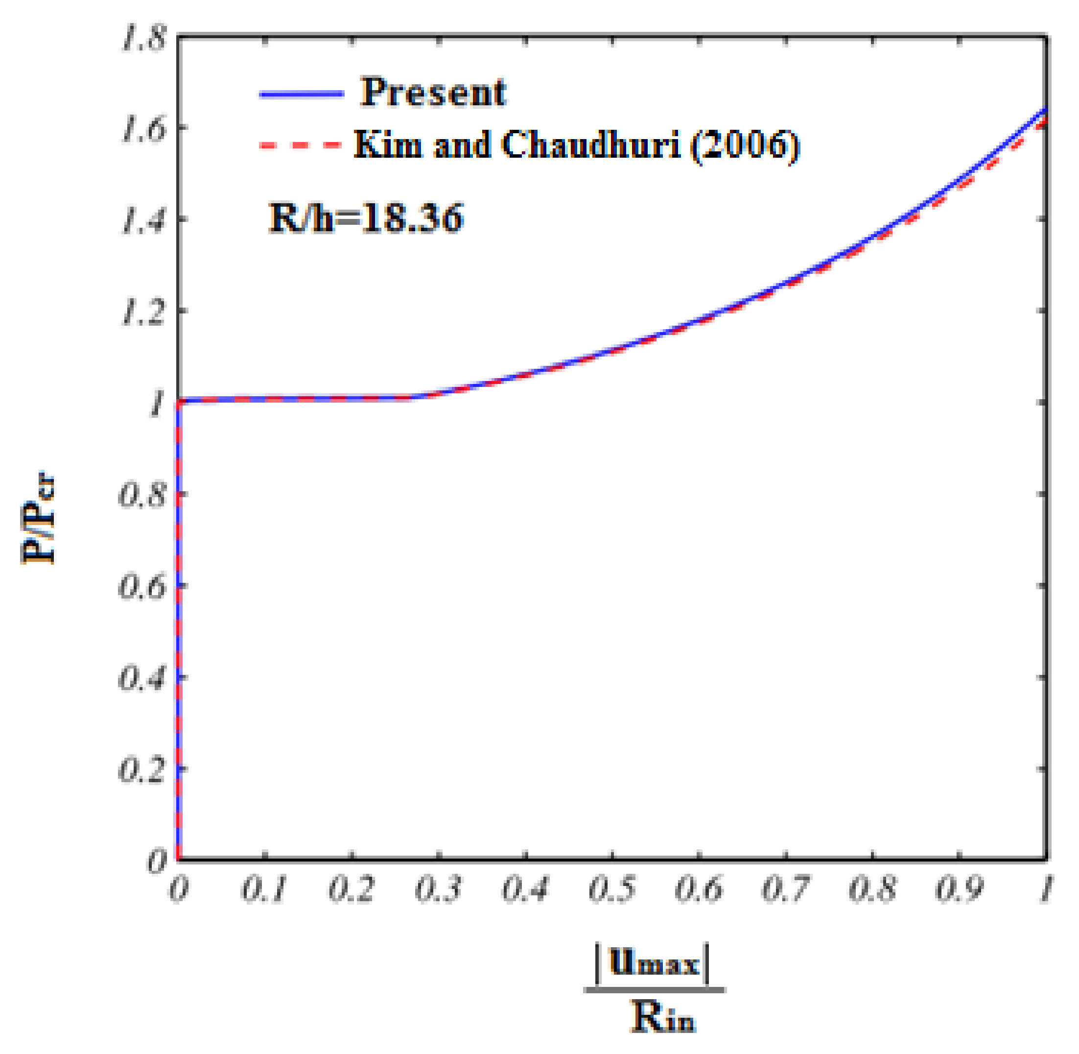
The post-buckling phase up to the collapse state of rings constructed of an isotropic material is here evaluated and compared with predictions by Kim and Chaudhuri [70]. To this end, it is enough to consider γ G P L = 0 , e0 = 0. The mechanical and geometrical properties are considered exactly the same as in [70]. Such comparative evaluation among our results and the reference ones by Kim and Chaudhuri [70] is depicted in Figure 3 in terms of dimensionless load-displacement curves, where R i n refers to the inner radius of the ring and p c r is the associated buckling load. Based on these plots, it is worth noting the perfect matching among all results, thus confirming the high accuracy of the proposed method against the available literature.

4.2. Post-Buckling Behavior of FG-GPL Porous Ring

In this section, we evaluate the post-buckling behavior of FG porous rings reinforced by GPLs for different porosity distributions and GPL patterns, porosity coefficients, and weight fractions of nanofillers. More specifically, the post-buckling behavior of the structure is here evaluated for two different points, A and B, as reported in Figure 1.
To this end, the geometry is defined by means of rin = 0.975 m and rout = 1.025 m, while assuming the following mechanical properties, i.e., E m = 130 GPa, ρ m = 8960 kg/m3, υ m = 0.34 and E G P L = 1.01 TPa, ρ G P L = 1062.5 kg/m3, υ G P L = 0.186 w G P L = 1.5 μm, l G P L = 2.5 μm, t G P L = 1.5 nm for GPLs.

4.2.1. The Effect of GPLs Distributions and Weight Fractions

Figure 4 shows the influence of various GPL patterns on the post-buckling behavior of FG porous rings at point A. As can be seen, the equilibrium path shows a bifurcation point following a stable post-buckling path. Besides, the maximum buckling and post-buckling strength is related to a GPLX distribution, while the minimum values are associated to a GPL-V distribution. Also, the values of buckling load and post-buckling deformation are approximately the same for rings reinforced with GPL-V and GPL-O distributions, whose findings could be useful to scientists and engineers for many practical design purposes. Note that the maximum difference of critical buckling load for various GPL patterns is approximately 33%. Figure 5, also shows the effect of various weight fractions of nanofiller on the post-buckling response of FG porous ring reinforced by GPLs (always for point A). By increasing the weight fraction of nanofillers, the buckling and post-buckling strength of rings considerably increases (by approximately about 90%). On the other hand, by introducing about 1% of nanofiller, the stiffness of the ring increases significantly, together with its buckling strength.

4.2.2. The Effect of Porosity Distribution and Coefficient of Porosity

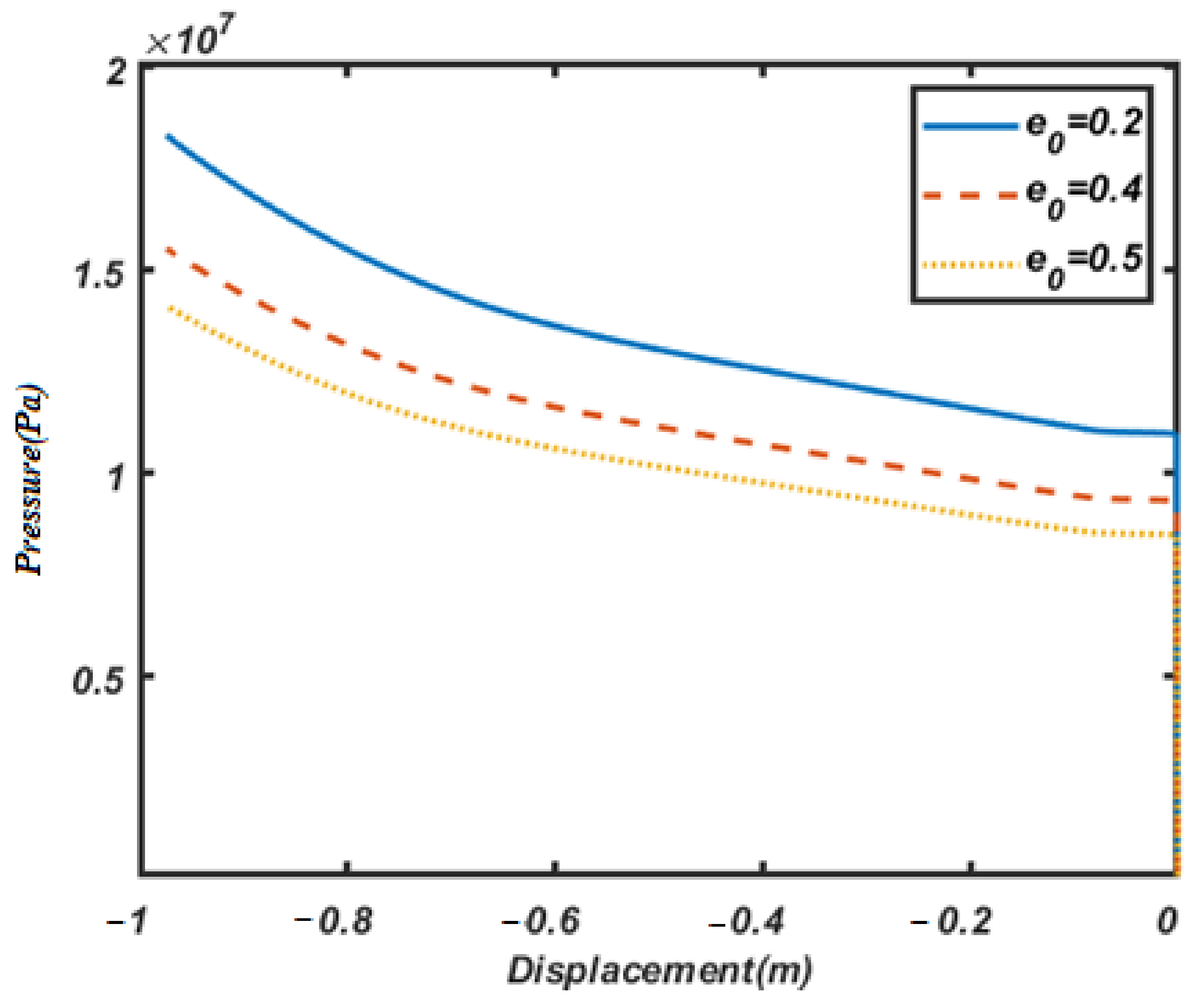
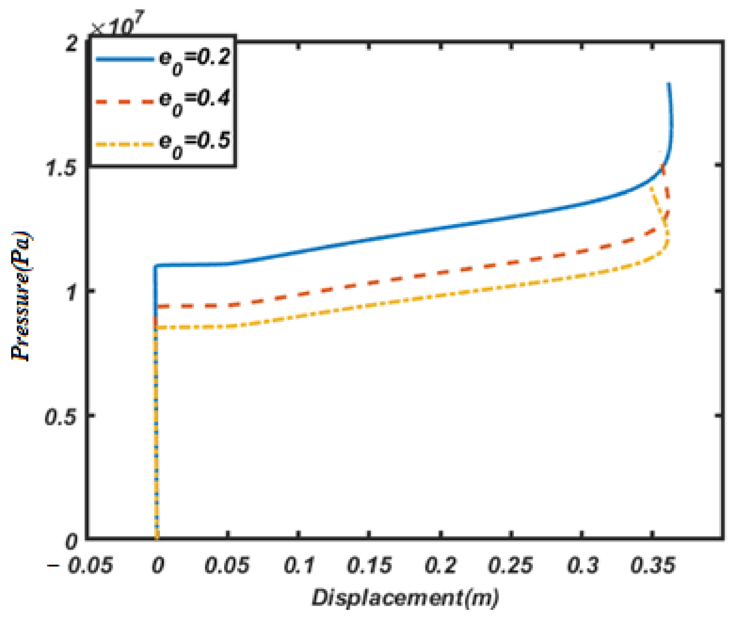
Let us study now the effect of the porosity coefficient on the post-buckling behavior of FG porous rings reinforced by GPLs, whose results are depicted in Figure 6 for point A.
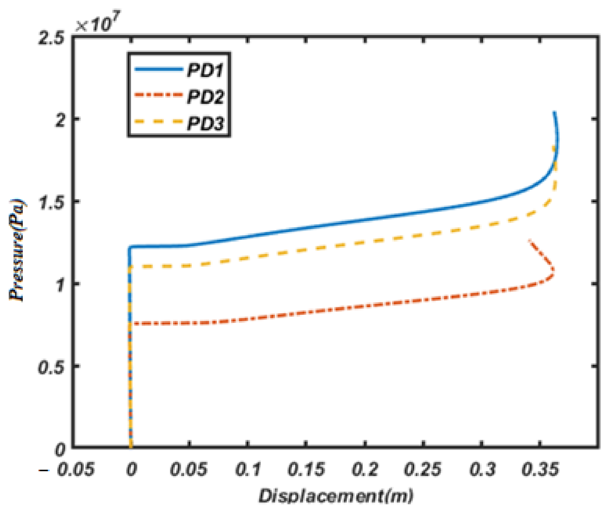
By increasing the porosity coefficient, the buckling load and post-buckling strength of the ring decreases due to a decreased structural stiffness. By increasing the porosity coefficient from e0 = 0.2 to e0 = 0.5, the buckling load decreases by approximately of 28%. Figure 7 shows the influence of different porosity distributions on the post-buckling behavior of FG porous rings reinforced by graphene platelet (point A). The maximum buckling load and post-buckling strength is related to PD1 while the minimum values belong to PD2. It is worth observing, also, that the effect of porosity distribution on the buckling load and post-buckling strength of the ring is much more pronounced than that associated to the weight fraction of nanofillers or other parameters. On the other hand, the difference between the buckling load stemming from a PD1 and PD2 is approximately more than 100%. This means that the distribution of porosity plays an important role in the structural stiffness, which represents a key aspect for different engineering applications involving cellular and porous structures, primarily, the aerospace industry.
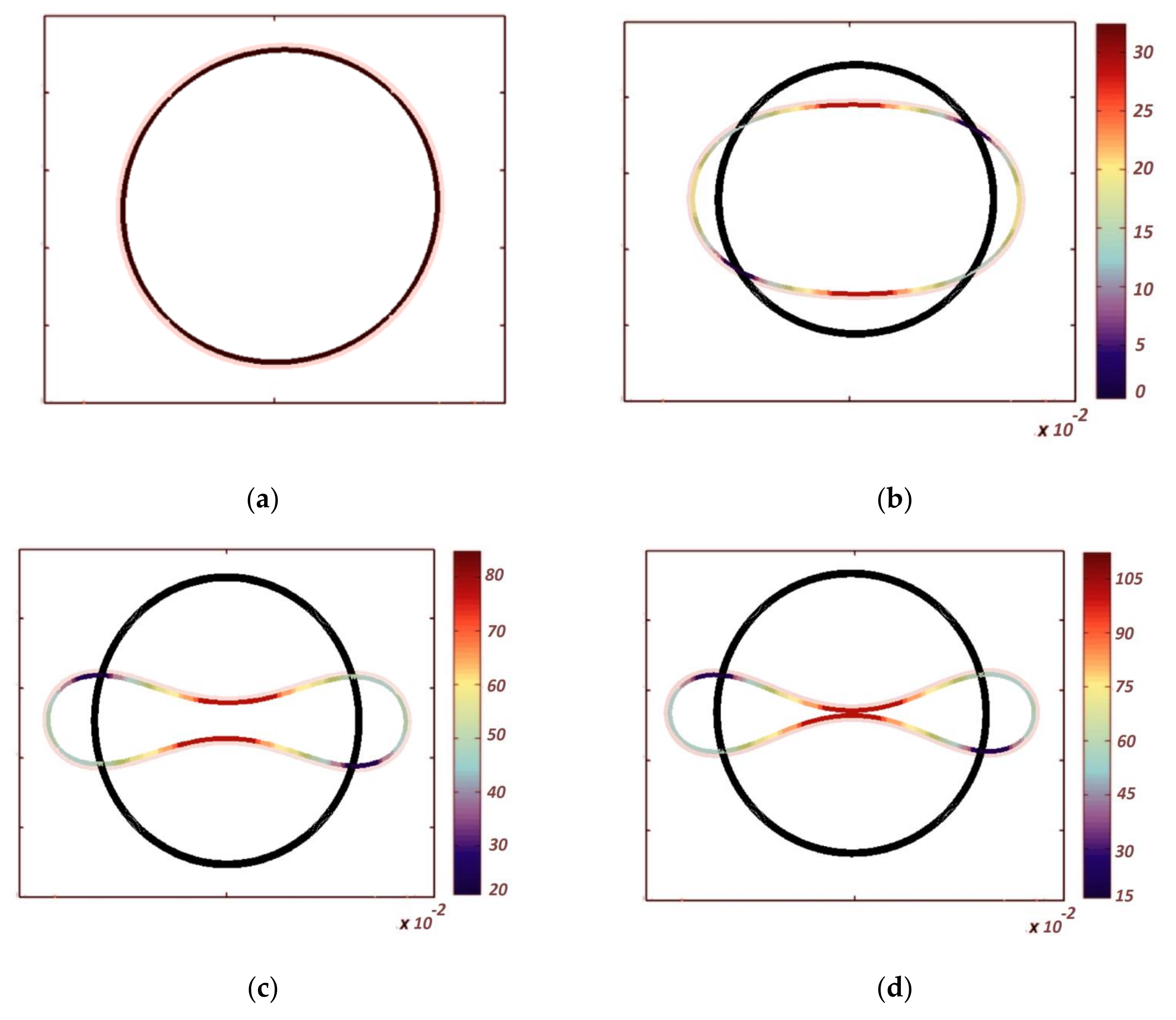
The same parametric investigation has been repeated for a different point, B, of the FG porous ring reinforced by graphene platelet, still concluding the same findings already highlighted for point A, as visible in Figure 8, Figure 9, Figure 10 and Figure 11, despite the fact that the flattening phenomena are always observed when the structure starts collapsing. To study the post-buckling behavior of structures, most previous studies have referred to the post-buckling path based on a maximum displacement, although such maximum displacement may vary in any step with the point location. For a deep comprehension about the post-buckling behavior of structures, the post-buckling curves should be drawn for various points. Figure 12 finally represents the deformed configuration of the porous ring reinforced by graphene platelets in the post-buckling phase up to collapse for various loading configurations.

5. Conclusions

Rings can be considered as the pipelines part in submarines structures, subjected to a hydrostatic uniform external pressure, and for which an accurate buckling analysis is required. Besides, FG porous reinforced GPLs can be considered as a novel material for many practical applications, primarily, for the aerospace industry.
In such a context, this article has focused on the post-buckling behavior up to the collapse state of rings constructed of FG porous materials reinforced with graphene platelet. A 2D plane stress elasticity theory has been proposed herein in conjunction with a finite element approach and iterative Newton–Raphson scheme to solve the governing equations of the ring. Due to the importance of an accurate prediction of the post-buckling path of rings, the 2D elasticity theory and the complete nonlinear Green strain field rather than simple shell theories and Von Kármán nonlinearities have been considered in this work. More specifically, a 2D elasticity theory has considered the thickness stretching and it has been revealed to predict accurately the post-buckling behavior of the selected structures. Based on the systematic sensitivity study of the buckling and post-buckling strength of FG-GPL porous rings, for different porosity coefficients, weight fractions of nanofiller, as well as different porosity distributions and GPL patterns, the following findings can be summarized:
  • The maximum and minimum buckling loads and post-buckling strength of the ring belong to GPLX and GPL-O distributions. Besides, for GPL-V and GPL-O, the buckling load values and post-buckling paths are approximately the same;
  • The maximum and minimum buckling loads and post-buckling strength of the ring belong to PD1 and PD2, respectively;
  • The impact of porosity distribution on the buckling load and post-buckling path is more pronounced than the effect of weight fractions of nanofillers;
  • By increasing the weight fraction of nanofiller about 1%, the buckling value and post-buckling strength considerably increase (by approximately 80%);
  • By increasing the porosity coefficient from 0.2 to 0.5, the buckling load and post-buckling strength decreases (by approximately 28%);
  • The behavior of the post-buckling path of the ring may vary from one point to another.

Author Contributions

Methodology, S.B., E.Z., M.B., F.T. and R.D.; Software, S.B., E.Z., M.B. and F.T.; Validation, S.B., E.Z., M.B., F.T. and R.D.; Formal analysis, S.B., E.Z., F.T. and R.D.; Investigation, S.B., E.Z., M.B. and R.D.; Writing—original draft, S.B. and E.Z.; Writing—review & editing, M.B., F.T. and R.D. All authors have read and agreed to the published version of the manuscript.

Funding

This research received no external funding.

Conflicts of Interest

The authors declare no conflict of interest.

References

  1. Wah, T. Buckling of thin circular rings under uniform pressure. Int. J. Solids Struct. 1967, 3, 967–974. [Google Scholar] [CrossRef]
  2. Hazel, A.L.; Mullin, T. On the buckling of elastic rings by external confinement. Philos. Trans. R. Soc. A Math. Phys. Eng. Sci. 2017, 375, 20160227. [Google Scholar] [CrossRef] [PubMed]
  3. Azzuni, E.; Guzey, S. A perturbation approach on buckling and postbuckling of circular rings under nonuniform loads. Int. J. Mech. Sci. 2018, 137, 86–95. [Google Scholar] [CrossRef]
  4. Seide, P.; Weingarten, V.I. Buckling of circular rings and long cylinders enclosing an elastic material under uniform external pressure. ARS J. 1962, 32, 680–687. [Google Scholar] [CrossRef]
  5. Azzuni, E.; Guzey, S. Behavior of thin elastic circular rings with large deformations under nonuniform loads. J. Press. Vessel. Technol. 2019, 141, 011201. [Google Scholar] [CrossRef]
  6. Kerdegarbakhsh, M.; Kiani, Y.; Esfahani, S.E.; Eslami, M.R. Postbuckling of FGM rings. Int. J. Mech. Sci. 2014, 85, 187–195. [Google Scholar] [CrossRef]
  7. Lagrange, R.; Jiménez, F.L.; Terwagne, D.; Brojan, M.; Reis, P. From wrinkling to global buckling of a ring on a curved substrate. J. Mech. Phys. Solids 2016, 89, 77–95. [Google Scholar] [CrossRef]
  8. Thurston, G.A. Application of Newton’s Method to the Postbuckling of Rings under Pressure Loadings; NASA: Washington, DC, USA, 1989. [Google Scholar]
  9. Sills, L.B.; Budiansky, B. Postbuckling ring analysis. J. App. Mech T ASME 1978, 45, 208–210. [Google Scholar] [CrossRef]
  10. Asemi, K.; Kiani, Y. Postbuckling up to collapse of polar orthotropic linearly elastic rings subjected to external pressure. Int. J. Struct. Stab. Dyn. 2016, 16, 1450091. [Google Scholar] [CrossRef]
  11. Zhang, Q.; Li, Z.; Huang, H.; Zhang, H.; Zheng, H.; Kuai, H. Stability of submarine bi-material pipeline-liner system with novel polyhedral composites subjected to thermal and mechanical loading fields. Mar. Struct. 2023, 90, 103424. [Google Scholar] [CrossRef]
  12. Smith, B.H.; Szyniszewski, S.; Hajjar, J.F.; Schafer, B.W.; Arwade, S.R. Steel foam for structures: A review of applications, manufacturing and material properties. J. Constr. Steel Res. 2012, 71, 1–10. [Google Scholar] [CrossRef]
  13. Lefebvre, L.P.; Banhart, J.; Dunand, D.C. Porous metals and metallic foams: Current status and recent developments. Adv. Eng. Mater. 2008, 10, 775–787. [Google Scholar] [CrossRef]
  14. Babaei, M.; Asemi, K. Stress analysis of functionally graded saturated porous rotating thick truncated cone. Mech. Based Des. Struct. Mach. 2022, 50, 1537–1564. [Google Scholar] [CrossRef]
  15. Babaei, M.; Kiarasi, F.; Asemi, K.; Dimitri, R.; Tornabene, F. Transient thermal stresses in FG porous rotating truncated cones reinforced by graphene platelets. Appl. Sci. 2022, 12, 3932. [Google Scholar] [CrossRef]
  16. Kiarasi, F.; Babaei, M.; Asemi, K.; Dimitri, R.; Tornabene, F. Three-dimensional buckling analysis of functionally graded saturated porous rectangular plates under combined loading conditions. Appl. Sci. 2021, 11, 10434. [Google Scholar] [CrossRef]
  17. Mousavi, S.B.; Amir, S.; Jafari, A.; Arshid, E. Analytical solution for analyzing initial curvature effect on vibrational behavior of PM beams integrated with FGP layers based on trigonometric theories. Adv. Nano Res. 2021, 10, 235–251. [Google Scholar]
  18. Bouhadra, A.; Menasria, A.; Rachedi, M.A. Boundary conditions effect for buckling analysis of porous functionally graded nanobeam. Adv. Nano Res. 2021, 10, 313–325. [Google Scholar]
  19. Keleshteri, M.M.; Jelovica, J. Nonlinear vibration analysis of bidirectional porous beams. Eng. Comput. 2022, 38, 5033–5049. [Google Scholar] [CrossRef]
  20. Beg, M.S.; Khalid, H.M.; Yasin, M.Y.; Hadji, L. Exact third-order static and free vibration analyses of functionally graded porous curved beam. Steel Compos. Struct. Int. J. 2021, 39, 1–20. [Google Scholar]
  21. Akbaş, Ş.D. Dynamic analysis of axially functionally graded porous beams under a moving load. Steel Compos. Struct. Int. J. 2021, 39, 811–821. [Google Scholar]
  22. Huang, W.; Tahouneh, V. Frequency study of porous FGPM beam on two-parameter elastic foundations via Timoshenko theory. Steel Compos. Struct. Int. J. 2021, 40, 139–156. [Google Scholar]
  23. Madenci, E.; Özkılıç, Y.O. Free vibration analysis of open-cell FG porous beams: Analytical, numerical and ANN approaches. Steel Compos. Struct. Int. J. 2021, 40, 157–173. [Google Scholar]
  24. Rahmani, M.; Mohammadi, Y. Vibration of two types of porous FG sandwich conical shell with different boundary conditions. Struct. Eng. Mech. 2021, 79, 401–413. [Google Scholar]
  25. Xu, X.; Zhang, C.; Musharavati, F.; Sebaey, T.A.; Khan, A. Wave propagation analysis of porous functionally graded curved beams in the thermal environment. Struct. Eng. Mech. 2021, 79, 665–675. [Google Scholar]
  26. Farrokh, M.; Taheripur, M. Optimization of porosity distribution of FGP beams considering buckling strength. Struct. Eng. Mech. 2021, 79, 711–722. [Google Scholar]
  27. Yüksel, Y.Z.; Akbaş, D. Hygrothermal stress analysis of laminated composite porous plates. Struct. Eng. Mech. 2021, 80, 1–13. [Google Scholar]
  28. Chen, S.X.; Sahmani, S.; Safaei, B. Size-dependent nonlinear bending behavior of porous FGM quasi-3D microplates with a central cutout based on nonlocal strain gradient isogeometric finite element modelling. Eng. Comput. 2021, 37, 1657–1678. [Google Scholar] [CrossRef]
  29. Ebrahimi, F.; Farazmandnia, N.; Kokaba, M.R.; Mahesh, V. Vibration analysis of porous magneto-electro-elastically actuated carbon nanotube-reinforced composite sandwich plate based on a refined plate theory. Eng. Comput. 2021, 37, 921–936. [Google Scholar] [CrossRef]
  30. Xia, X.C.; Chen, X.W.; Zhang, Z.; Chen, X.; Zhao, W.M.; Liao, B.; Hur, B. Effects of porosity and pore size on the compressive properties of closed-cell Mg alloy foam. J. Magnes. Alloy. 2013, 1, 330–335. [Google Scholar] [CrossRef]
  31. Jena, S.K.; Chakraverty, S.; Malikan, M. Application of shifted Chebyshev polynomial-based Rayleigh–Ritz method and Navier’s technique for vibration analysis of a functionally graded porous beam embedded in Kerr foundation. Eng. Comput. 2021, 37, 3569–3589. [Google Scholar] [CrossRef]
  32. Rafiee, M.A.; Rafiee, J.; Wang, Z.; Song, H.; Yu, Z.Z.; Koratkar, N. Enhanced mechanical properties of nanocomposites at low graphene content. ACS Nano 2009, 3, 3884–3890. [Google Scholar] [CrossRef] [PubMed]
  33. Mittal, G.; Dhand, V.; Rhee, K.Y.; Park, S.J.; Lee, W.R. A review on carbon nanotubes and graphene as fillers in reinforced polymer nanocomposites. J. Ind. Eng. Chem. 2015, 21, 11–25. [Google Scholar] [CrossRef]
  34. Liew, K.M.; Lei, Z.X.; Zhang, L.W. Mechanical analysis of functionally graded carbon nanotube reinforced composites: A review. Compos. Struct. 2015, 120, 90–97. [Google Scholar] [CrossRef]
  35. Tornabene, F.; Bacciocchi, M.; Fantuzzi, N.; Reddy, J.N. Multiscale approach for three-phase CNT/polymer/fiber laminated nanocomposite structures. Polym. Compos. 2019, 40, E102–E126. [Google Scholar] [CrossRef]
  36. Jena, S.K.; Chakraverty, S.; Malikan, M.; Tornabene, F. Effects of surface energy and surface residual stresses on vibro-thermal analysis of chiral, zigzag, and armchair types of SWCNTs using refined beam theory. Mech. Based Des. Struct. Mach. 2022, 50, 1565–1579. [Google Scholar] [CrossRef]
  37. Zhou, J.; Yao, Z.; Chen, Y.; Wei, D.; Xu, T. Fabrication and mechanical properties of phenolic foam reinforced with graphene oxide. Polym. Compos. 2014, 35, 581–586. [Google Scholar] [CrossRef]
  38. Dong, Y.H.; Li, Y.H.; Chen, D.; Yang, J. Vibration characteristics of functionally graded graphene reinforced porous nanocomposite cylindrical shells with spinning motion. Compos. Part B Eng. 2018, 145, 1–13. [Google Scholar] [CrossRef]
  39. Shahgholian-Ghahfarokhi, D.; Rahimi, G.; Khodadadi, A.; Salehipour, H.; Afrand, M. Buckling analyses of FG porous nanocomposite cylindrical shells with graphene platelet reinforcement subjected to uniform external lateral pressure. Mech. Based Des. Struct. Mach. 2019, 49, 1059–1079. [Google Scholar] [CrossRef]
  40. Shahgholian-Ghahfarokhi, D.; Safarpour, M.; Rahimi, A. Torsional buckling analyses of functionally graded porous nanocomposite cylindrical shells reinforced with graphene platelets (GPLs). Mech. Based Des. Struct. Mach. 2021, 49, 81–102. [Google Scholar] [CrossRef]
  41. Dong, Y.H.; He, L.W.; Wang, L.; Li, Y.H.; Yang, J. Buckling of spinning functionally graded graphene reinforced porous nanocomposite cylindrical shells: An analytical study. Aerosp. Sci. Technol. 2018, 82, 466–478. [Google Scholar] [CrossRef]
  42. Chen, D.; Yang, J.; Kitipornchai, S. Nonlinear vibration and postbuckling of functionally graded graphene reinforced porous nanocomposite beams. Compos. Sci. Technol. 2017, 142, 235–245. [Google Scholar] [CrossRef]
  43. Kitipornchai, S.; Chen, D.; Yang, J. Free vibration and elastic buckling of functionally graded porous beams reinforced by graphene platelets. Mater. Des. 2017, 116, 656–665. [Google Scholar] [CrossRef]
  44. Yang, J.; Chen, D.; Kitipornchai, S. Buckling and free vibration analyses of functionally graded graphene reinforced porous nanocomposite plates based on Chebyshev-Ritz method. Compos. Struct. 2018, 193, 281–294. [Google Scholar] [CrossRef]
  45. Zhou, Z.; Ni, Y.; Tong, Z.; Zhu, S.; Sun, J.; Xu, X. Accurate nonlinear buckling analysis of functionally graded porous graphene platelet reinforced composite cylindrical shells. Int. J. Mech. Sci. 2019, 151, 537–550. [Google Scholar] [CrossRef]
  46. Ansari, R.; Hassani, R.; Gholami, R.; Rouhi, H. Buckling and Postbuckling of Plates Made of FG-GPL-Reinforced Porous Nanocomposite with Various Shapes and Boundary Conditions. Int. J. Struct. Stab. Dyn. 2021, 21, 2150063. [Google Scholar] [CrossRef]
  47. Yaghoobi, H.; Taheri, F. Analytical solution and statistical analysis of buckling capacity of sandwich plates with uniform and non-uniform porous core reinforced with graphene nanoplatelets. Compos. Struct. 2020, 252, 112700. [Google Scholar] [CrossRef]
  48. Tao, C.; Dai, T. Isogeometric analysis for postbuckling of sandwich cylindrical shell panels with graphene platelet reinforced functionally graded porous core. Compos. Struct. 2021, 260, 113258. [Google Scholar] [CrossRef]
  49. Nguyen, Q.H.; Nguyen, L.B.; Nguyen, H.B.; Nguyen-Xuan, H. A three-variable high order shear deformation theory for isogeometric free vibration, buckling and instability analysis of FG porous plates reinforced by graphene platelets. Compos. Struct. 2020, 245, 112321. [Google Scholar] [CrossRef]
  50. Priyanka, R.; Twinkle, C.M.; Pitchaimani, J. Stability and dynamic behavior of porous FGM beam: Influence of graded porosity, graphene platelets, and axially varying loads. Eng. Comput. 2021, 38 (Suppl. S5), 4347–4366. [Google Scholar] [CrossRef]
  51. Barati, M.R.; Zenkour, A.M. Analysis of postbuckling of graded porous GPL-reinforced beams with geometrical imperfection. Mech. Adv. Mater. Struct. 2019, 26, 503–511. [Google Scholar] [CrossRef]
  52. Li, Z.; Zhang, Q.; Shen, H.; Xiao, X.; Kuai, H.; Zheng, J. Buckling performance of the encased functionally graded porous composite liner with polyhedral shapes reinforced by graphene platelets under external pressure. Thin Walled Struct. 2023, 183, 110370. [Google Scholar] [CrossRef]
  53. Xiao, X.; Zhang, Q.; Zheng, J.; Li, Z. Analytical model for the nonlinear buckling responses of the confined polyhedral FGP-GPLs lining subjected to crown point loading. Eng. Struct. 2023, 282, 115780. [Google Scholar] [CrossRef]
  54. Xiao, X.; Bu, G.; Ou, Z.; Li, Z. Nonlinear in-plane instability of the confined FGP arches with nanocomposites reinforcement under radially-directed uniform pressure. Eng. Struct. 2022, 252, 113670. [Google Scholar] [CrossRef]
  55. Anirudh, B.; Ganapathi, M.; Anant, C.; Polit, O. A comprehensive analysis of porous graphene-reinforced curved beams by finite element approach using higher-order structural theory: Bending, vibration and buckling. Compos. Struct. 2019, 222, 110899. [Google Scholar] [CrossRef]
  56. Li, Z.; Zheng, J. Nonlinear stability of the encased functionally graded porous cylinders reinforced by graphene nanofillers subjected to pressure loading under thermal effect. Compos. Struct. 2020, 233, 111584. [Google Scholar] [CrossRef]
  57. Bahaadini, R.; Saidi, A.R.; Arabjamaloei, Z.; Ghanbari-Nejad-Parizi, A. Vibration analysis of functionally graded graphene reinforced porous nanocomposite shells. Int. J. Appl. Mech. 2019, 11, 1950068. [Google Scholar] [CrossRef]
  58. Kiarasi, F.; Babaei, M.; Sarvi, P.; Asemi, K.; Hosseini, M.; Omidi Bidgoli, M. A review on functionally graded porous structures reinforced by graphene platelets. J. Comput. Appl. Mech. 2021, 52, 731–750. [Google Scholar]
  59. Arshid, E.; Amir, S.; Loghman, A. Thermal buckling analysis of FG graphene nanoplatelets reinforced porous nanocomposite MCST-based annular/circular microplates. Aerosp. Sci. Technol. 2021, 111, 106561. [Google Scholar] [CrossRef]
  60. Ebrahimi, F.; Mohammadi, K.; Barouti, M.M.; Habibi, M. Wave propagation analysis of a spinning porous graphene nanoplatelet-reinforced nanoshell. Waves Random Complex Media 2021, 31, 1655–1681. [Google Scholar] [CrossRef]
  61. Arshid, E.; Amir, S.; Loghman, A. Static and dynamic analyses of FG-GNPs reinforced porous nanocomposite annular micro-plates based on MSGT. Int. J. Mech. Sci. 2020, 180, 105656. [Google Scholar] [CrossRef]
  62. Affdl, J.H.; Kardos, J.L. The Halpin-Tsai equations: A review. Polym. Eng. Sci. 1976, 16, 344–352. [Google Scholar] [CrossRef]
  63. Adab, N.; Arefi, M.; Amabili, M. A comprehensive vibration analysis of rotating truncated sandwich conical microshells including porous core and GPL-reinforced face-sheets. Compos. Struct. 2022, 279, 114761. [Google Scholar] [CrossRef]
  64. Ebrahimi, F.; Ezzati, H. A Machine-Learning-Based Model for Buckling Analysis of Thermally Affected Covalently Functionalized Graphene/Epoxy Nanocomposite Beams. Mathematics 2023, 11, 1496. [Google Scholar] [CrossRef]
  65. Liu, G.R. A step-by-step method of rule-of-mixture of fiber-and particle-reinforced composite materials. Compos. Struct. 1997, 40, 313–322. [Google Scholar] [CrossRef]
  66. Guo, H.; Yang, T.; Żur, K.K.; Reddy, J.N.; Ferreira, A.J.M. Effect of thermal environment on nonlinear flutter of laminated composite plates reinforced with graphene nanoplatelets. In Modeling and Computation in Vibration Problems, Volume 1: Numerical and Semi-analytical Methods; IOP Publishing: Bristol, UK, 2021. [Google Scholar]
  67. Babaei, H. Thermomechanical analysis of snap-buckling phenomenon in long FG-CNTRC cylindrical panels resting on nonlinear elastic foundation. Compos. Struct. 2022, 286, 115199. [Google Scholar] [CrossRef]
  68. Bathe, K.J. Finite Element Procedures; Klaus-Jurgen Bathe: Cambridge, MA, USA, 2006. [Google Scholar]
  69. Zienkiewicz, O.C.; Taylor, R.L.; Zhu, J.Z. The Finite Element Method: Its Basis and Fundamentals; Elsevier: Amsterdam, The Netherlands, 2005. [Google Scholar]
  70. Kim, D.; Chaudhuri, R.A. Postbuckling of moderately thick imperfect rings under external pressure. J. Eng. Mech. 2006, 132, 1273–1276. [Google Scholar] [CrossRef]
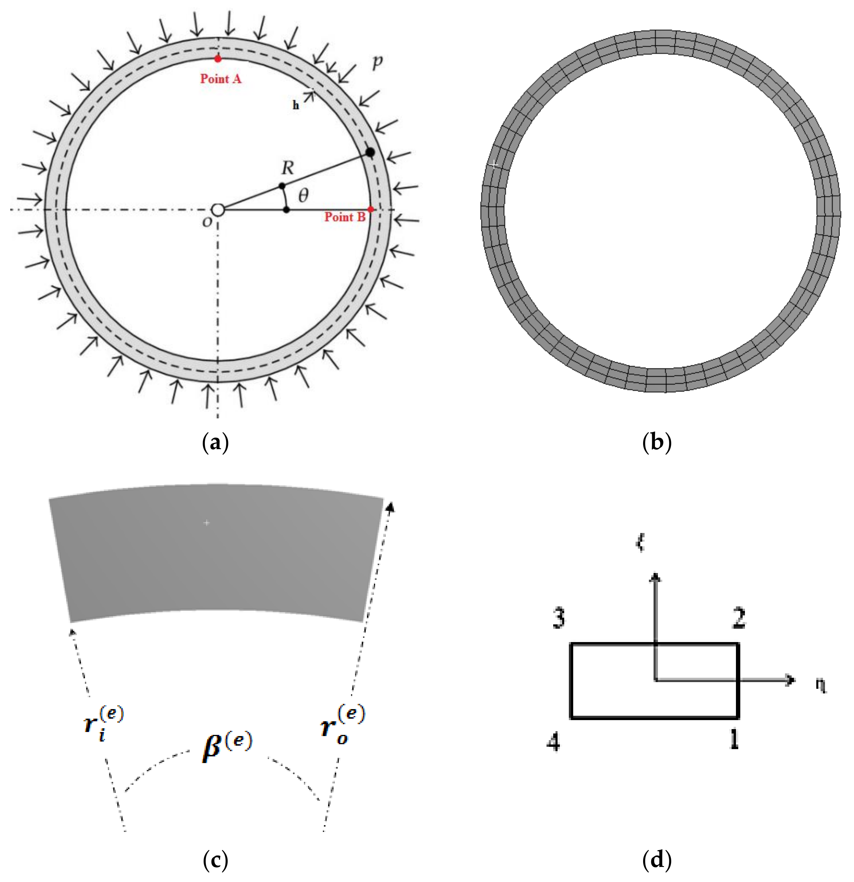
Figure 1. Geometry and coordinate system of ring (a), meshed ring (b), annular sector element (c), and local coordinate system (d).
Mathematics 11 02421 g001
Figure 2. Porosity patterns and GPL distributions.
Mathematics 11 02421 g002
Figure 3. Post-buckling compressive state up to the collapse for an isotropic ring [70].
Mathematics 11 02421 g003
Figure 4. The effect of different GPL patterns on the post-buckling behavior of FG porous rings reinforced by GPLs (point A).
Mathematics 11 02421 g004
Figure 5. The effect of different weigh fraction of nanofiller on the post-buckling behavior of FG porous rings reinforced by GPLs (point A).
Mathematics 11 02421 g005
Figure 6. The effect of different porosity coefficients on the post-buckling behavior of FG porous rings reinforced by GPLs (point A).
Mathematics 11 02421 g006
Figure 7. The effect of different porosity distributions on the post-buckling behavior of FG porous rings reinforced by GPLs (point A).
Mathematics 11 02421 g007
Figure 8. The effect of various GPL patterns on the post-buckling behavior of FG porous rings reinforced by GPLs (point B).
Mathematics 11 02421 g008
Figure 9. The effect of different weight fractions of nanofiller on the post-buckling behavior of FG porous rings reinforced by GPLs (point B).
Mathematics 11 02421 g009
Figure 10. The effect of different porosity coefficients on the post-buckling behavior of FG porous rings reinforced by GPLs (point B).
Mathematics 11 02421 g010
Figure 11. The effect of different porosity distributions on the post-buckling behavior of FG porous rings reinforced by GPLs (point B).
Mathematics 11 02421 g011
Figure 12. The deformed shape of an FG porous ring reinforced by GPLs under different loading conditions: 96 KPa (a), 9.15 MPa (b), 13.048 MPa (c), and 14.496 MPa (d).
Mathematics 11 02421 g012
Table 1. Porosity coefficients for PD1, PD2, and PD3.
e 0 e 0 * α
0.10.17380.9361
0.20.34420.8716
0.30.51030.8064
0.40.67080.7404
0.50.82310.6733
0.60.96120.6047
Disclaimer/Publisher’s Note: The statements, opinions and data contained in all publications are solely those of the individual author(s) and contributor(s) and not of MDPI and/or the editor(s). MDPI and/or the editor(s) disclaim responsibility for any injury to people or property resulting from any ideas, methods, instructions or products referred to in the content.