Article

Tachism: Tri-Port Antenna with Triple Notching Characteristic and High Isolation System for MIMO Application

1
School of Engineering & Applied Sciences, ISRA University, Islamabad 44000, Pakistan
2
Department of Electrical Engineering, Yeungnam University, Gyeongsan 38541, Republic of Korea
3
Department of Electrical and Computer Engineering, Islamabad Campus, COMSATS University Islamabad, Islamabad 45550, Pakistan
4
Department of Information and Communication Engineering, Yeungnam University, Gyeongsan 38541, Republic of Korea
*
Author to whom correspondence should be addressed.
These authors contributed equally to this work.
Mathematics 2022, 10(23), 4491; https://doi.org/10.3390/math10234491
Submission received: 17 October 2022 / Revised: 12 November 2022 / Accepted: 19 November 2022 / Published: 28 November 2022
(This article belongs to the Special Issue Connected Mathematics for Next Generation Communication Networks)

Abstract

:
A novel ultra-wideband (UWB) KAYI-shaped and common KITE-shaped ground plane tri-port antenna is proposed. The proposed research work has a small size of (30 × 30 × 1.6 mm 3 ). The MIMO antenna elements are placed in a KAYI-shaped (Y-shaped) with a symmetric phase shift of 120 between the nearby MIMO antennas element improving the isolation. The antenna’s gain is more than 5 dBi for the entire bands of WiMax, WLAN, and X-band satellite communication. The suggested work includes notches at 3.2 GHz, 5.2 GHz, and 8.9 GHz, respectively. The notching characteristics are made possible by L-shaped slits for the WiMax band, the inverted U-shaped slot for WLAN, while the third is created by the interaction between the L-shaped and U-shaped notching elements. Results were measured after making the prototype antenna on the FR-4 substrate. The proposed antenna has good impedance matching for 2–20 GHz and three notching characteristics with high isolation among the MIMO elements. Mean effective gain (MEG), envelope correlation coefficient (ECC), and total active reflection coefficient (TARC) are the diversity metrics of MIMO antennas which are in good comparison to the proposed antenna. The antenna is a good candidate for deployment in wireless communication and MIMO applications.

1. Introduction

High-data technology and a low-cost wide bandwidth are suitable means of enhancing the data rate. The rate of transmission is the requirement of communication systems nowadays. In recent years, researchers have studied high data rates and increased channel capacity. The ultra-wideband (UWB) technology is capable to provide both of these properties when combined with MIMO systems. It is already used in short-range communication, radar, and position-tracking applications. The diversity technology performance of multiple-input–multiple-output (MIMO) systems enables high transmission and mitigates the multiple path fading to enhance the channel capacity. In 2002, the federal communication commission (FCC) introduced ultra-wideband technology and provided the frequency spectrum ( 3.1 10.6 ) GHz to it with limited power emission [1,2]. The frequency band of ultra-wideband technology is used in commercial and a wide variety of mobile applications [3,4,5]. The allocated narrow band within the UWB, such as worldwide interoperability microwave access WiMax (3.1–3.9 GHz), C-band (4–4.3 GHz), WLAN (5.1–5.9 GHz), and X-band satellite communication (7.9–8.9 GHz) have high traffic in addition to interference with UWB. Different techniques have been stated in the past to perform band notching within the UWB technology in order to co-exist with the other band of communication.
The UWB-MIMO antenna can achieve notching by placing slits and slots on either the main radiator or on the ground side. Decoupling structures can provide good isolation between the different elements of MIMO [6]. As a result, the antenna may achieve a wider bandwidth along with low mutual coupling. A slot is added to the main radiator which, along with parasitic elements, are used in quasi-self-complementary antennas to introduce multiple notches [7]. In [8], different band notches are introduced in the polygonal-shaped monopole antenna by inserting multiple L-shaped strips. Filters are also used to suppress certain bands. The bandpass filter (BPF) or band stop filters may be used to remove the interference as in [9,10].
The UWB-MIMO antenna introduced F-shaped stubs in the ground plane to achieve low mutual coupling and better diversity parameters [11]. The antenna achieved better diversity performance and low mutual coupling between the antenna elements. In [12], a tapered-fed compact size, UWB-MIMO diversity antenna with dual notching characteristics is presented. The tapered fed microstrip slot antenna with a small size acts as a single element for radiation, and an inverted L-shape is used to introduce the notches at the WLAN and IEEE-INSAT C-band. In [13], the compact dual-band MIMO antenna has low mutual coupling between the elements which creates notches for WLAN and X-band satellites using orthogonal polarization. One slot is on the upper side of the patch, and two slots are etched at the bottom to reduce the interference between notching elements and further enhance the impedance matching.
The two main things that are considered in designing an MIMO antenna system are an appropriate size and low mutual coupling between the antenna elements. The coupling between the elements of antenna is reduced with the incremental distance in array size. However, increasing the distance between antenna elements will create a larger antenna size. Different methods have been used for the miniaturization and reduction in mutual coupling of an antenna such as cross polarization, orthogonal elements, electromagnetic band gap (EBG) structure [14], meander line, in [15], defective ground structure (DGS) [16,17,18], parasitic element [19,20], meta-material with neutralized line [21], and slits/slots or the use of carbon black film [22].
In [23], a quad port MIMO Filtenna with a compact dimension of 50 × 50 mm 2 was presented. The MIMO antenna was designed based on the novel COVID-19 virus shape with a co-planar waveguide feeding structure. A bandpass filter was loaded on top of the waveguide to achieve a triple-notch band, and a decoupling structure was used to decrease the mutual coupling. In a UWB-MIMO antenna, achieving low mutual coupling along with multiple notches in a compact size is challenging task. All these properties along with high isolation is achieved in [24,25,26].
In [27], a MIMO antenna with four slot antenna elements with a rhombic shape in the ground plane produced triple notches for WiMax, WLAN, and X-band communication. With a compact size of 34 × 34 mm 2 , the L-shaped and C-shaped are used for WiMax and WLAN notches, and the electromagnetic gap structure is used for the X-band communication notch. Parasitic strips are used for high isolation between the adjacent antenna elements. In [28], a compact millimeter-wave MIMO antenna for 5G applications is designed with high isolation of more than 25 dB was attained using the cross-polarization technique. Similarly, in [29], isolation improvement for the UWB-MIMO antenna system using a slotted stub was reported with the implementation of extended ground plane along with the decoupling elements of cross shape. In [30], a sub-6 GHz dual-band 8 × 8 MIMO antenna for 5G smartphones was designed with low isolation using short neutral line. Self-decoupled structures are used in [31] to improve the isolation between antenna elements. All the literature has been focused on creating a separate notching element for each notch in the frequency domain. Later, mutual coupling between the elements of antenna is reduced by using the techniques found in the literature. However, notching with mutually exclusive elements are compromised in either the size of the overall design or with high mutual coupling between the notching elements. On the contrary, this paper introduces only two notching elements to create three band notches using the coupling between the notching elements. This way, the size of the overall design is not compromised and coupling between the notching elements are used as an additional advantage.

1.1. Contribution of the Research

In this paper, 1 × 3 elements of the UWB-MIMO antenna along with notches at WiMax, WLAN, and X-band for satellite communication were presented using only two notching elements. The contributions of the paper are as follows:
1.
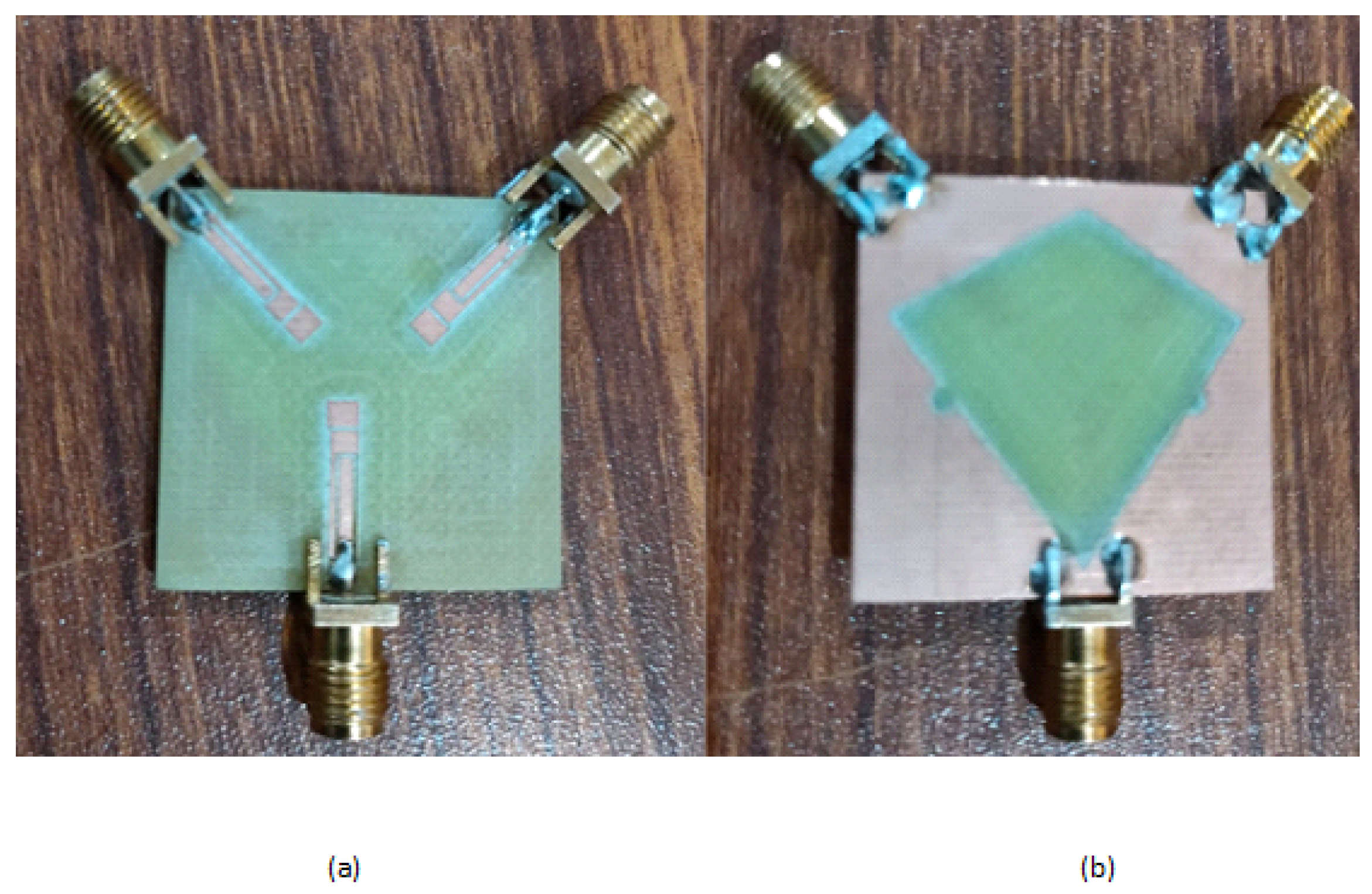
A third notch for the X-band was successfully created with the help of mutual coupling between already placed notching elements for WiMax and WLAN. To the best of the authors’ knowledge, the element’s structure is based on the novel shape of the Ottoman Empire’s KAYI-shape flag with a common KITE ground plane.
2.
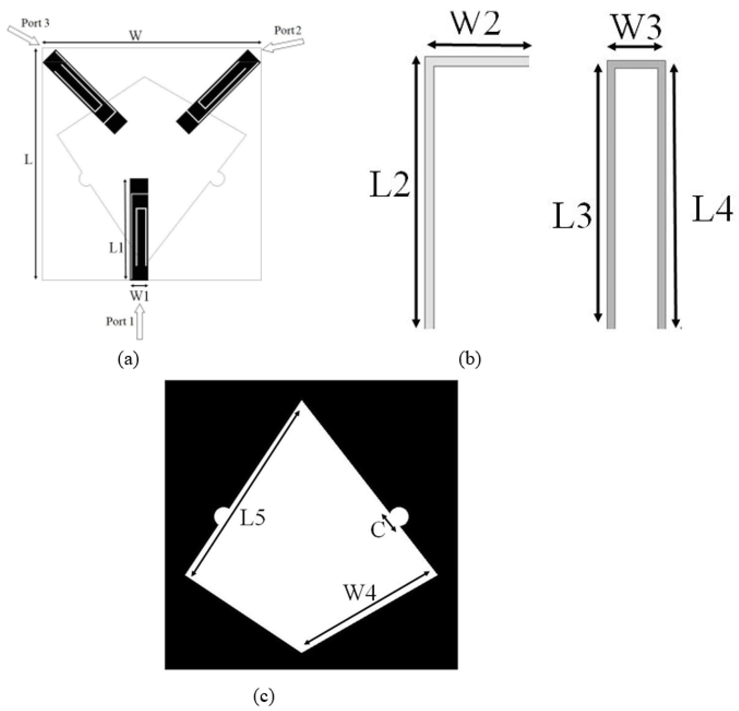
The UWB-MIMO antenna has a size of 30 × 30 × 1.6 mm 3 . The radiating elements are placed with a symmetrical phase of 120 from each other. This tri port symmetry is beneficial in many ways and help to avoid various constraints of the PCB design, whereby the antenna and other electronic components are placed in a small space and compact geometry.
3.
The space on PCB is sometimes not inline to creating 1 × 4 or 2 × 2 MIMO configurations. Therefore, there is a need for a circular configuration to have three MIMO antennas with a symmetric phase of 120 . The symmetric phase difference between the antenna elements produced at least 33 % lower mutual coupling in the MIMO system as compared to a 1 × 4 MIMO configuration on the same scale.
4.
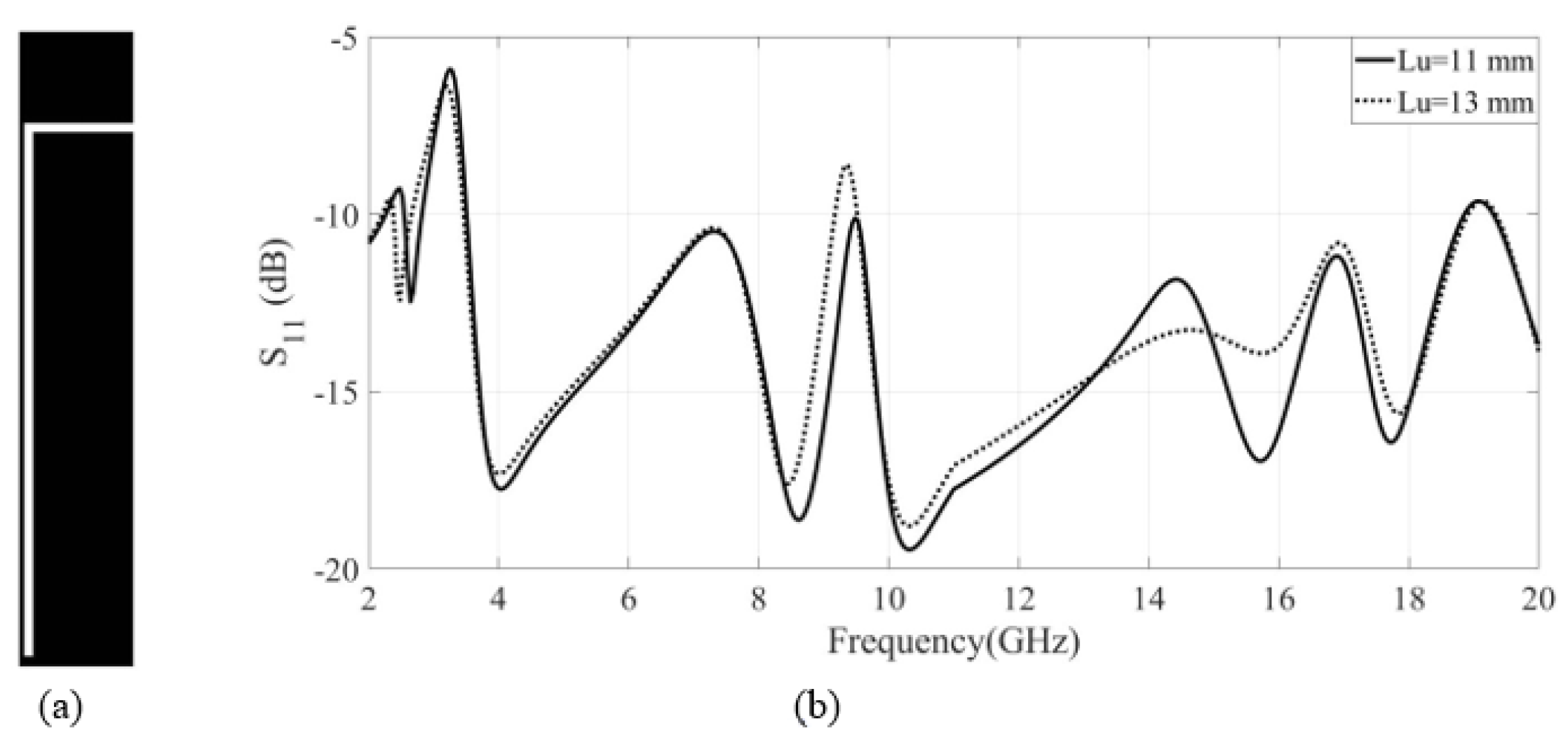
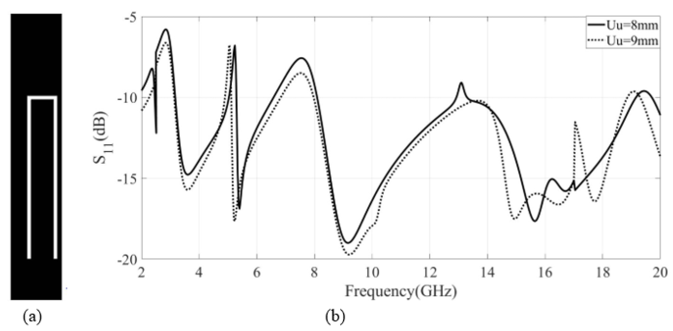
The parasitic strip are loaded with slits having inverted an L-shaped and inverted U-shaped slots, which are used for the notching characteristics of WiMax and WLAN bands, respectively.
5.
The simulated and fabricated KAYI-KITE-shaped UWB-MIMO antenna have a small size, good impedance matching, high mutual coupling between the antenna elements, good diversity performance, and triple-notched band characteristics using only two notching elements. The mutual coupling between the notching elements of the antenna are used to take advantage of creating the third notch band.

1.2. Organization of the Article

This paper is organized as follows: in Section 2, the UWB antenna design, notching characteristics, coupling of notching elements with each other, and proposed MIMO design are presented in detail. In Section 3, the results are discussed comprehensively, i.e., S-parameter analysis, radiation patterns, peak gain and radiation efficiency. In Section 4, the diversity performance, fabrication, and measurement results are discussed. The article is concluded in Section 5.

2. Antenna Designing and Operation Mechanism

The proposed antenna was fabricated on an FR-4 substrate with a thickness of 1.6 mm and has a dielectric constant ϵ r of 4.4 . The design comprises a KAYI Shape geometry, comprising three antennas separated by a phase symmetry of 120 . L u - and U u -shaped slits and slots were introduced in the patch element for notching characteristics at WiMax and WLAN. The length and placement of these notching elements were intelligently selected to create a third band notch at the higher frequency for the elimination of the X-band of satellite communication. A defective KITE shape was carved on the ground for better impedance matching. The optimized design was simulated on electromagnetic simulation HFSS.

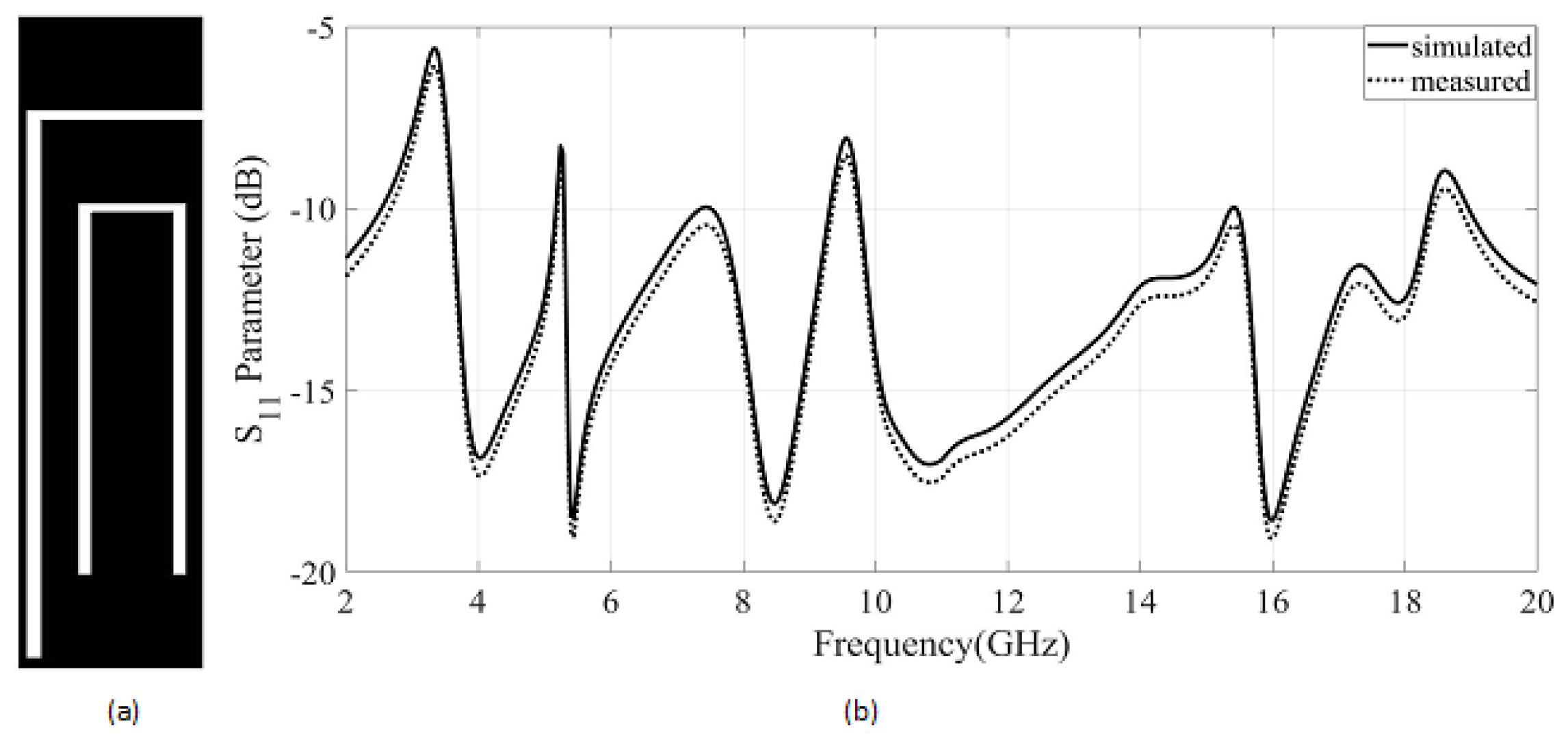
2.1. Design of UWB Antenna

The UWB antenna element (Tachism) with a KAYI shape is presented in Figure 1, and dimension values of different parameters of the proposed antenna is presented in Table 1. The proposed antenna elements are suitable for UWB applications along with notching characteristics. The UWB antenna specifications can be achieved by placing a single patch element on top of the substrate and carving a defected KITE shape on the ground plane. A resonance point in simulation affects the UWB performance parameters at some frequencies within the whole band. The impedance bandwidth matching of these bands can be enhanced by placing symmetrical semi-circular curves of diameter C = 1 mm on top of the KITE shape which is at the ground plane. The reflection coefficient of UWB elements of MIMO design is presented in Figure 2. The result shows that the antenna is working excellently for a specified UWB band. Additionally the extended bandwidth is achieved for the entire 3–20 GHz frequency band.

2.2. Design of Band Notch Elements

The proposed antennas (Tachism) are designed for triple notching characteristics in WiMax, WLAN, and X-band for satellite communication. Interference is found in these bands due to the co-existence of UWB. Notching characteristics are introduced into the UWB characteristics by etching slits and slots on the patch to eliminate the interference within the entire range.

2.2.1. WiMax Band Notch Element Design

The notch for the WiMax is introduced in the UWB characteristic by etching the patch with an inverted L-shape element. The notching formula determines the length of the L u -shaped slit:
f W i M a x = c 4 L u ϵ r e f f
L u = L 2 + W 2
where L u is the total length inverted L-shaped slit on the radiating patch, f W i M a x is the center of notching frequency at the WiMax band, ϵ r e f f is the dielectric constant of the FR-4 substrate, and c is the speed of light. The length is calculated from the formula, which gives L u = 11 mm for the resonance center frequency of 3.2 GHz. However, the width of the L u slit = 0.2 mm. The analysis shows that the resonance frequency for the notch will be 3.06 GHz a decrease of 4.3 % whilst the length increase by 15 % (i.e., L u increases from 11 mm to 13 mm). Figure 3 shows that placing an inverted L-shaped slit on the patch introduces a WiMax notch band characteristic.

2.2.2. WLAN Band Notch Element Design

The FCC allocated 5–6 GHz bandwidth for the WLAN within the UWB band. The interference mitigation for the WLAN band is required within UWB. An inverted U-shaped slot was etched in the radiating patch to overcome the interference for the WLAN band. The inverted U–shaped slot of length U u = 8 mm is calculated using the expression Equation (3) with the changed length, and the width of the inverted U-shaped slot U u is 0.2 mm in order to produce the notch at the WLAN band. The length of the inverted U-shaped slot is:
f W L A N = c 4 U u ϵ r e f f
U u = L 3 + L 4 + W 3
where f W L A N is a center notch frequency for WLAN, U u is the total length of the U-shaped slot as provided in Equation (4). Figure 4 shows the suppression in the WLAN band. The figure shows that the length of an inverted U-shaped slot and the notching frequency are in inverse relationship. For 5.2 GHz, the length of the U-shaped slot is U u is 8 mm. The length of the U u slot increases 11 % from 8 mm to 9 mm will create the decrease in frequency of 4 % as the notching frequency reduces from to 5.2 to 5 GHz.

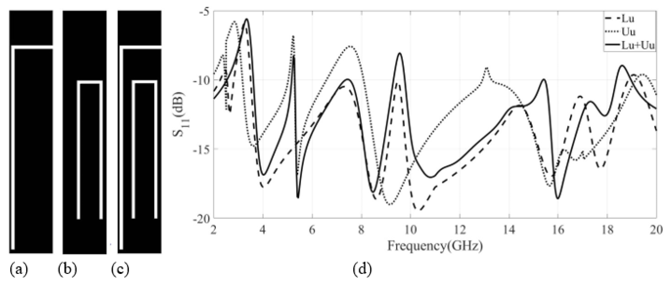
2.2.3. Satellite Band Notch Using Mutual Coupling

The X-Band for satellite communication is from 7.2 to 8.4 GHz as allocated by the federal commission communication (FCC). Reliable communication is not possible because of interference due to the co-existence between the UWB and X-band. The satellite band notch is required to be implemented. The satellite band notch is achieved by creating specific mutual coupling between WiMax and WLAN element. A notch at 8.9 GHz in the UWB characteristic is achieved by selecting the appropriate wavelength λ = 3 mm. Figure 5 shows the achieved notching characteristics using mutual coupling. The coupling of notches is presented in Figure 6. The figure shows that the combined effect of the L-shaped notching element with the U-shaped notching element over the entire frequency band shifted a bit along with the creation of a third band notch. However, with the addition of both notching elements, i.e., L u and U u , a shift of 2 % in the center frequency in the WLAN band notch toward the high frequency band is observed. Similarly, the center frequency for WiMax notch is shifted by 13 % toward the lower frequency end.

3. Results and Discussion

The proposed KAYI shape UWB-MIMO 3-port antenna is fabricated on the FR-4 substrate. Simulated and measured results are compared with each other and verified through calculations. The radiation patterns, efficiency, and peak gain performance are tested in an anechoic chamber. Further discussions of each of these results are discussed in the subsequent sections.

3.1. S-Parameters Analysis

The KAYI shape UWB-MIMO antenna is fabricated with an overall size of 30 × 30 mm 2 and a substrate thickness of 1.6 mm. Figure 6 shows the antenna’s simulated and measured S 11 result. The result shows that the antenna has a good impedance matching profile for the UWB characteristic, along with implementation of three band stop characteristics. The band stop range at the WiMax is from 2.7 to 3.3 GHz, the WLAN band stop characteristic is from 5.1 to 5.3 GHz, and the notch band for the satellite provider network is from 8.6 to 9.1 GHz. The S 11 parameters are almost same for the three ports due to the symmetry of the antenna. The simulated and measured results are in good agreement with each other.

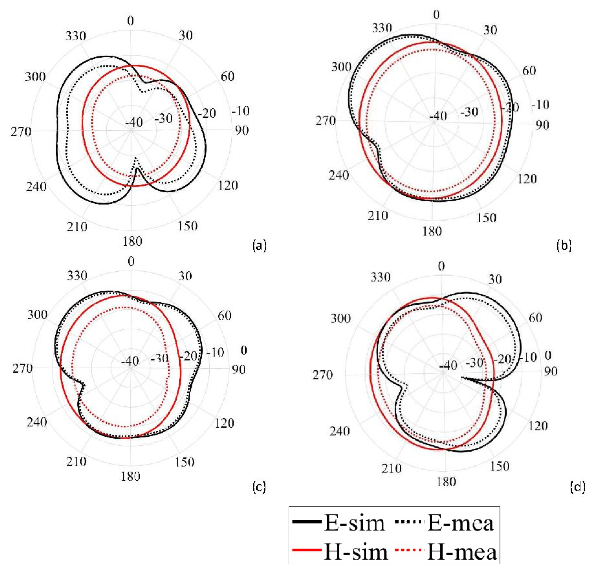
3.2. Radiation Patterns
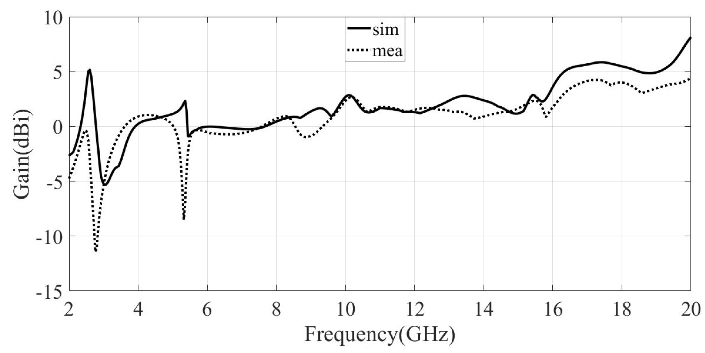
Radiation patterns for the proposed antenna are observed at 3.2 GHz, 5.2 GHz, 6 GHz, and 8.9 GHz. The measured and simulated E-H plane radiation patterns for band stop and in-band frequencies are presented in Figure 7. The measured and simulated H-plane radiation patterns were found to be omnidirectional, while the E-plane radiation patterns for notch frequencies of 3.2 GHz, 5.2 GHz, and 8.9 GHz show the directional patterns. The radiation patterns are found to be stable for the entire UWB.

3.3. Peak Gain

The peak gain of the UWB three-port MIMO is presented in Figure 8. The gain of the antenna varies from −7 dBi to 5.5 dBi. At the band notching frequencies ( 3.2 GHz and 5.2 GHz), the antenna gain is sufficiently reduced to suppress the transmitted or received signal. The gain is significantly high at in-band frequencies, especially at the high frequency end.

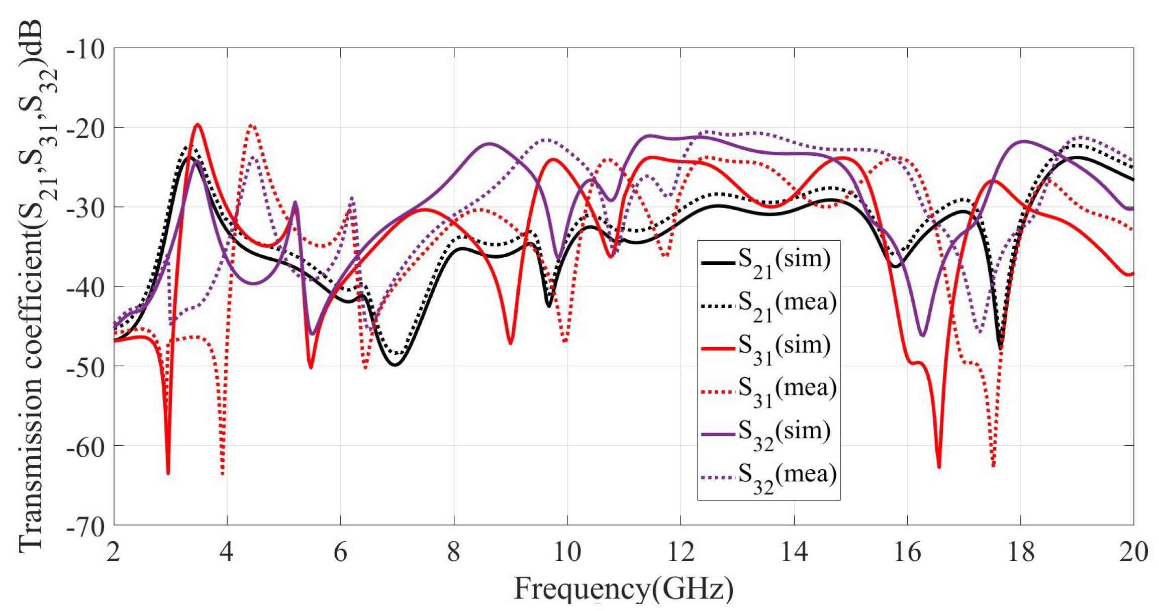
3.4. Transmission Coefficient

The transmission coefficient for three ports of the KAYI MIMO antennas is presented in Figure 9. The S 12 , S 13 are the mutual coupling curves between the adjacent antennas. The results show that the antennas are well-isolated from each other. The isolation of MIMO is below 20 dB in the entire frequency band.

3.5. MIMO Decoupling Structure

The KAYI-shaped 3 × 1 port MIMO antenna is designed with band notching elements. The antenna size is compact and has weak coupling between all three antennas. The coupling between the antennas is further reduced by placing the antennas at a distance of 120 from each other. Because of the symmetrical circular configuration, the MIMO antennas are sufficiently isolated and less interactive with each other. Figure 9 shows that the S 21 , S 31 , and S 23 have low mutual coupling between the elements of the antenna. The simulated and measured results are found to be in good comparison with each other.

4. Diversity Performance

The diversity performance of the proposed antenna shows the applicability for the connective link of wireless network requirements. The envelope correlation coefficient (ECC), diversity gain (DG), mean effective gain (MEG), channel capacity loss (CCL), and total active reflection coefficient (TARC) are examined in this section for the evaluation of diversity performance. Each parameter is discussed in the subsequent sections.

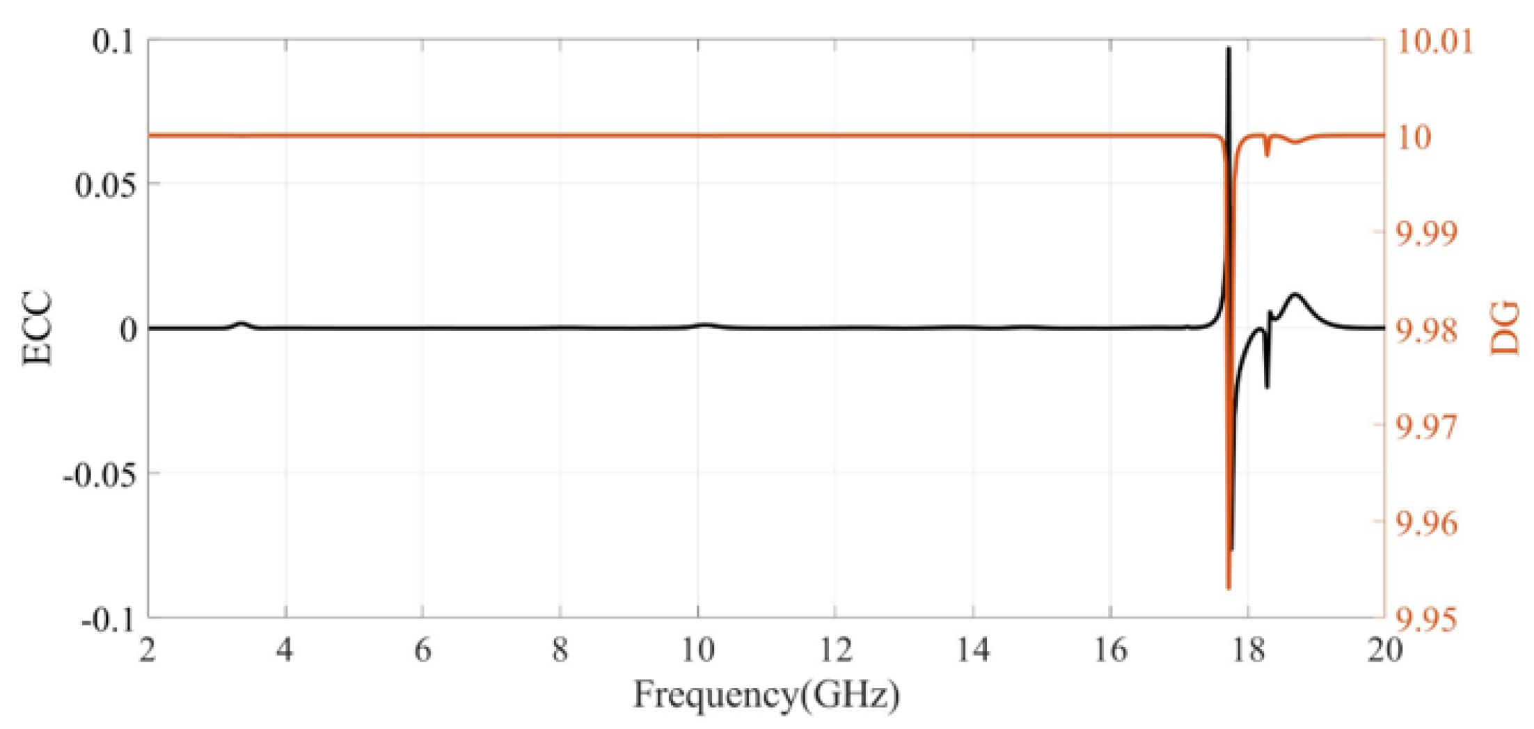
4.1. Envelope Correlation Coefficient (ECC)

The diversity performance parameter called ECC is used to show the how much a single antenna radiation pattern is independent from the other antennas. The correlation between the radiation pattern of the MIMO system antennas determines the channel isolation in a wireless communication link. The ECC shows the correlation between the antennas in the MIMO system. The ECC for the MIMO antenna must approach very low values. The lower value of an ECC or zero shows that the antennas have low correlation between the elements. The ECC can be determined from the S-parameters by the following formula:
ECC = | S i i * S i j + S j i * S j j | 2 [ 1 ( | S i i | 2 | S j i | 2 | ) ] [ 1 ( | S j j | 2 | S i j | 2 | ) ]
The threshold value for ECC should be less than 0.5 for the MIMO antenna system, which guarantees the reliable communication link. Figure 10 shows that the ECC value of the MIMO antenna system is less than the required threshold (ECC 0.5 ).

4.2. Diversity Gain (DG)

The diversity gain is another parameter of the diversity performance of the antenna. The diversity gain can be measured as the communication link reliability in a MIMO system as it shows the reduction in the fading of the channel while combining two or more independent antennas. The diversity gain is calculated from the formula given below:
DG = 10 1 ( ECC ) 2
The threshold of diversity gain should be nearly equal to 10. The diversity gain is related to ECC as the values of ECC reduce to zero; then, the values of diversity gain will approach 10. Figure 10 shows the diversity gain of the proposed antenna which is nearly close to ideal values.

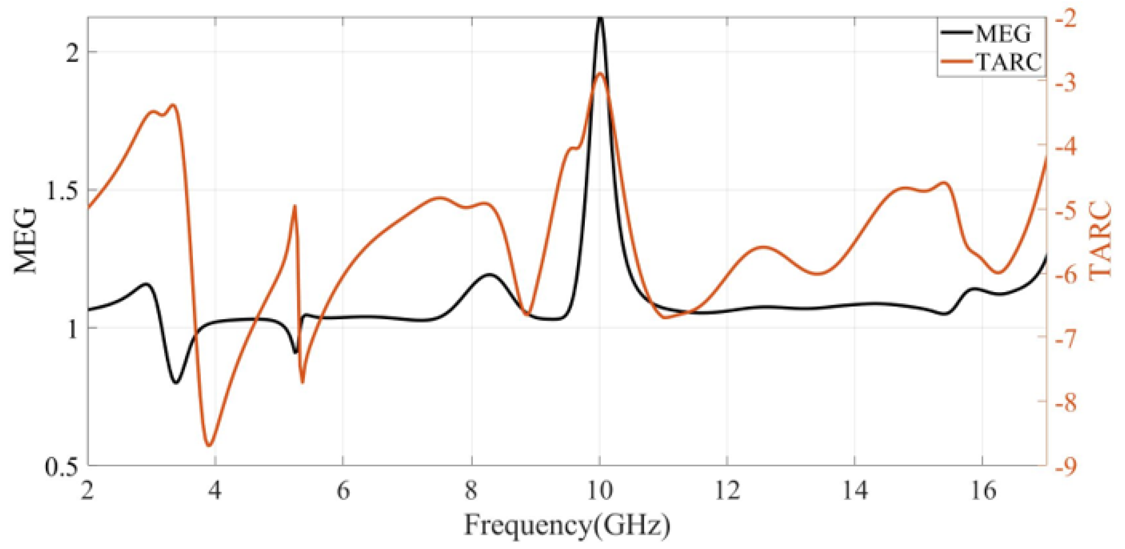
4.3. Mean Effective Gain (MEG)

The mean effective gain of the antenna measures the antenna performance of the multi-path environment. The ratio of the received power to the total incident power is the measure of the mean effective gain. The mean effective gain ratio is less than 3 for the effective MIMO antenna performance which shows compliance with this figure of merit. The mean effective gain is calculated from the following formula:
MEG = 1 ( | S i i | 2 | S i j | 2 | ) 2 1 ( | S i j | 2 | S j j | 2 | ) 2
Figure 11 shows the MEG of the MIMO antenna. The figure shows that the MEG for the MIMO antenna is less than 3 for the entire band.

4.4. Total Active Reflection Coefficient (TARC)

TARC is the ratio of the square root of total reflected power to the square root of the total incident power. The TARC shows the return loss of a single MIMO antenna when placed in the arrangement of the array, in the presence of mutual coupling. The TARC is calculated using the S-parameters of the antenna.
TARC = ( S i i + S i j ) 2 + ( S j i + S j j ) 2 2
The TARC should be less than 0 dB for the MIMO antenna system. The TARC result is shown in Figure 11. The graph shows that the total active reflection coefficient is less than 0 dB for the entire band.

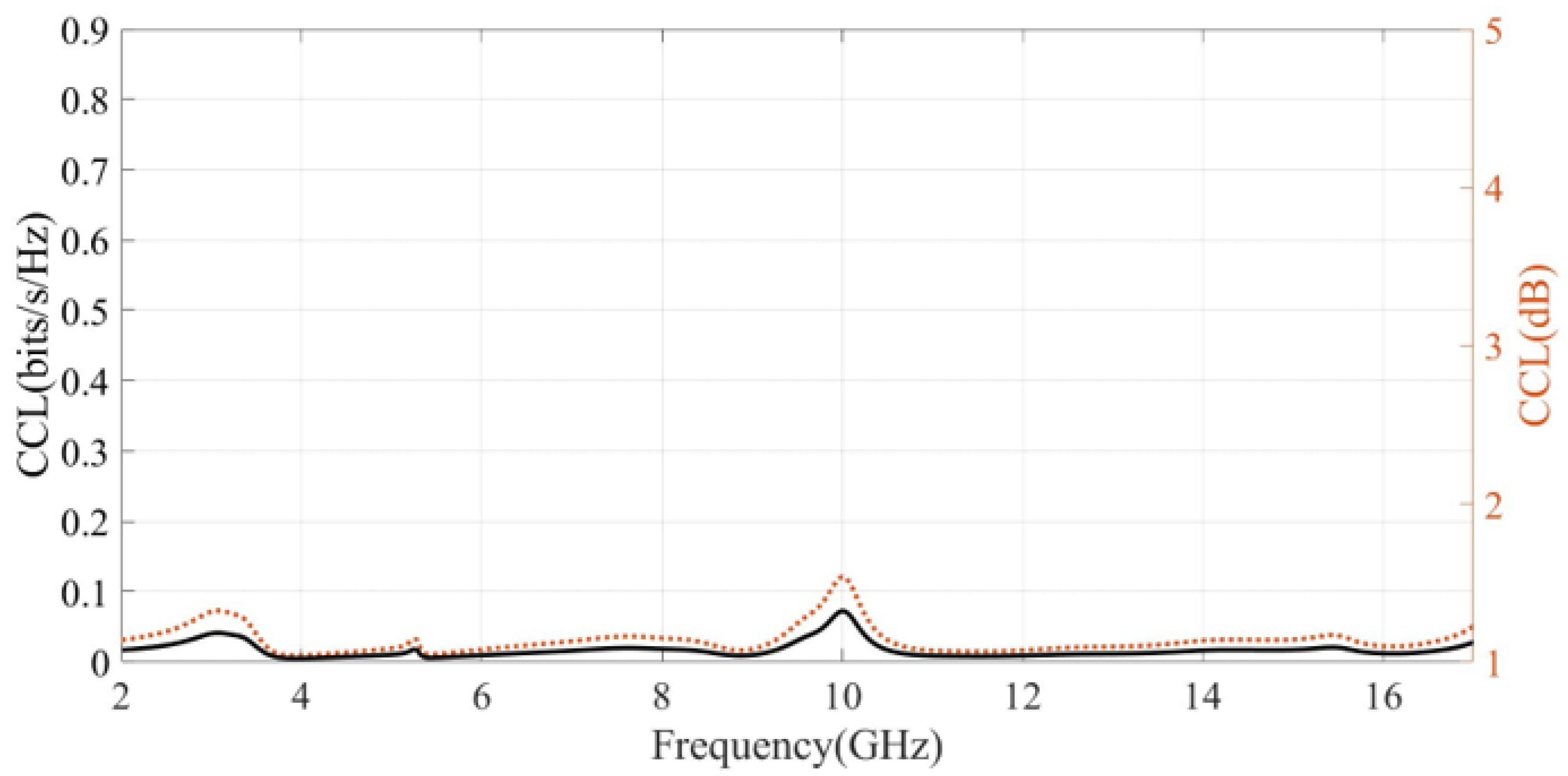
4.5. Channel Capacity Loss (CCL)

The CCL is another important parameter of diversity performance. The CCL shows the maximum data rate at which the transmission may persist with negligible loss. The CCL can be determined using the S-parameter of the antenna. The formula for CCL is given below:
CCL = ln ( [ A B ] [ C D ] )
where
A = 1 | S i i | 2 + | S i j | 2
B = 1 | S j j | 2 + | S j i | 2
C = S j j * S j i + S j i * S i i
D = S i i * S i j + S j i * S j j
The maximum acceptable value of CCL in a MIMO system is below 0.4 bits/s/Hz. Figure 12 shows the CCL performance of the system. The graph shows that the CCL value is significantly below the threshold value, which means that the proposed MIMO system is practically applicable. Finally, the prototype of the proposed antenna is shown in Figure 13.

4.6. Comparison Table with Existing Models

Comparison Table 2 shows the advantages of the proposed UWB-MIMO antenna with other previous works. The proposed antennas have better performance in different parameters with the reported design [8,11,12,13,20,23,24,25,26,27]. The proposed design has one advantage over the previous one and takes advantage of the mutual coupling of notching elements to create a third notch band. The proposed antenna achieved a three band notching characteristic with compact size due to only two notching elements. The other parameters such as ECC, DG, TARC, and CCL have better diversity performance compared to the reported work.

5. Conclusions

In this paper, a novel KAYI-shaped UWB-MIMO antenna has the characteristic of a triple band notch with a compact size of 30 × 30 × 1.6 mm 3 , which successfully achieved good impedance matching over the range of 2–20 GHz. The MIMO antenna shares a KITE-shaped ground plane. The notch is realized by etching the patch with an L-shaped parasitic slot for WiMax, a U-shaped parasitic slot for WLAN, mutual coupling between the L-shaped and U-shaped elements create a third notch band for X-band satellite communication. The measured results show that the proposed antenna has high isolation of S12 < 22 dB between the adjacent antenna elements and achieves a peak gain of 5.5 dBi. The diversity parameters ECC < 0.01 , TARC < 0.4 , and CCL < 0.2 have been successfully achieved. The MIMO antennas are placed in a symmetrical phase of 120 from each other. Good agreement between the simulated and measured results was obtained. The Tri-port antenna is a suitable candidate for UWB, MIMO, and WLAN system applications.

Author Contributions

Conceptualization, S.B. and T.K.; Methodology, S.B. and T.K.; Software, M.A.; Validation, M.A.; Formal analysis, T.K.; Writing—original draft, S.B.; Writing—review & editing, K.S.A. and A.N.; Supervision, K.S.A. and A.N.; Project administration, M.A.; Funding acquisition, A.N. All authors have read and agreed to the published version of the manuscript.

Funding

This research received no external funding.

Data Availability Statement

Not applicable.

Conflicts of Interest

The authors declare no conflict of interest.

References

  1. Aiello, G.R.; Rogerson, G.D. Ultra-wideband wireless systems. IEEE Microw. Mag. 2003, 4, 36–47. [Google Scholar] [CrossRef]
  2. Kaiser, T.; Zheng, F.; Dimitrov, E. An overview of ultra-wide-band systems with MIMO. Proc. IEEE 2009, 97, 285–312. [Google Scholar] [CrossRef]
  3. Staderini, E.M. UWB radars in medicine. IEEE Aerosp. Electron. Syst. Mag. 2002, 17, 13–18. [Google Scholar] [CrossRef]
  4. Zhang, J.; Orlik, P.V.; Sahinoglu, Z.; Molisch, A.F.; Kinney, P. UWB systems for wireless sensor networks. Proc. IEEE 2009, 97, 313–331. [Google Scholar] [CrossRef]
  5. Sobhani, B.; Paolini, E.; Giorgetti, A.; Mazzotti, M.; Chiani, M. Target tracking for UWB multistatic radar sensor networks. IEEE J. Sel. Top. Signal Process. 2013, 8, 125–136. [Google Scholar] [CrossRef]
  6. Tang, Z.; Wu, X.; Zhan, J.; Hu, S.; Xi, Z.; Liu, Y. Compact UWB-MIMO antenna with high isolation and triple band-notched characteristics. IEEE Access 2019, 7, 19856–19865. [Google Scholar] [CrossRef]
  7. Abd El-Hameed, A.; Wahab, M.; Elboushi, A.; Elpeltagy, M.S. Miniaturized triple band-notched quasi-self complementary fractal antenna with improved characteristics for UWB applications. AEU-Int. J. Electron. Commun. 2019, 108, 163–171. [Google Scholar] [CrossRef]
  8. Hosseini, H.; Hassani, H.; Amini, M. Miniaturised multiple notched omnidirectional UWB monopole antenna. Electron. Lett. 2018, 54, 472–474. [Google Scholar] [CrossRef]
  9. Li, J.; Zhang, X.; Chen, J.; Chen, J.; Da Xu, K.; Zhang, A. Circularly polarized co-designed filtering annular slot antenna. AEU-Int. J. Electron. Commun. 2018, 90, 30–35. [Google Scholar] [CrossRef]
  10. Ranjan, P.; Raj, S.; Upadhyay, G.; Tripathi, S.; Tripathi, V.S. Circularly slotted flower shaped UWB filtering antenna with high peak gain performance. AEU-Int. J. Electron. Commun. 2017, 81, 209–217. [Google Scholar] [CrossRef]
  11. Iqbal, A.; Saraereh, O.A.; Ahmad, A.W.; Bashir, S. Mutual coupling reduction using F-shaped stubs in UWB-MIMO antenna. IEEE Access 2017, 6, 2755–2759. [Google Scholar] [CrossRef]
  12. Chandel, R.; Gautam, A.K.; Rambabu, K. Tapered fed compact UWB MIMO-diversity antenna with dual band-notched characteristics. IEEE Trans. Antennas Propag. 2018, 66, 1677–1684. [Google Scholar] [CrossRef]
  13. Dkiouak, A.; Zakriti, A.; El Ouahabi, M. Design of a compact dual-band MIMO antenna with high isolation for WLAN and X-band satellite by using orthogonal polarization. J. Electromagn. Waves Appl. 2020, 34, 1254–1267. [Google Scholar] [CrossRef]
  14. Prabhu, P.; Malarvizhi, S. Novel double-side EBG based mutual coupling reduction for compact quad port UWB MIMO antenna. AEU-Int. J. Electron. Commun. 2019, 109, 146–156. [Google Scholar] [CrossRef]
  15. Kumar, N.; Kiran, K.U. Meander-line electromagnetic bandgap structure for UWB MIMO antenna mutual coupling reduction in E-plane. AEU-Int. J. Electron. Commun. 2020, 127, 153423. [Google Scholar] [CrossRef]
  16. Li, J.F.; Chu, Q.X.; Huang, T.G. A compact wideband MIMO antenna with two novel bent slits. IEEE Trans. Antennas Propag. 2011, 60, 482–489. [Google Scholar] [CrossRef]
  17. Luo, C.M.; Hong, J.S.; Zhong, L.L. Isolation enhancement of a very compact UWB-MIMO slot antenna with two defected ground structures. IEEE Antennas Wirel. Propag. Lett. 2015, 14, 1766–1769. [Google Scholar] [CrossRef]
  18. Satam, V.; Nema, S. Two element compact UWB diversity antenna with combination of DGS and parasitic elements. Wirel. Pers. Commun. 2018, 98, 2901–2911. [Google Scholar] [CrossRef]
  19. Khan, M.S.; Capobianco, A.D.; Asif, S.M.; Anagnostou, D.E.; Shubair, R.M.; Braaten, B.D. A compact CSRR-enabled UWB diversity antenna. IEEE Antennas Wirel. Propag. Lett. 2016, 16, 808–812. [Google Scholar] [CrossRef]
  20. Hassan, M.M.; Rasool, M.; Asghar, M.U.; Zahid, Z.; Khan, A.A.; Rashid, I.; Rauf, A.; Bhatti, F.A. A novel UWB MIMO antenna array with band notch characteristics using parasitic decoupler. J. Electromagn. Waves Appl. 2020, 34, 1225–1238. [Google Scholar] [CrossRef]
  21. Yuan, X.T.; He, W.; Hong, K.D.; Han, C.Z.; Chen, Z.; Yuan, T. Ultra-wideband MIMO antenna system with high element-isolation for 5G smartphone application. IEEE Access 2020, 8, 56281–56289. [Google Scholar] [CrossRef]
  22. Lin, G.S.; Sung, C.H.; Chen, J.L.; Chen, L.S.; Houng, M.P. Isolation improvement in UWB MIMO antenna system using carbon black film. IEEE Antennas Wirel. Propag. Lett. 2016, 16, 222–225. [Google Scholar] [CrossRef]
  23. Elsharkawy, R.R.; Abd El-Hameed, A.S.; El-Nady, S. Quad-port MIMO Filtenna with High Isolation Employing BPF with High out of Band Rejection. IEEE Access 2021, 10, 3814–3824. [Google Scholar] [CrossRef]
  24. Abd El-Hameed, A.S.; Wahab, M.G.; Elshafey, N.A.; Elpeltagy, M.S. Quad-Port UWB MIMO antenna based on LPF with vast rejection band. AEU-Int. J. Electron. Commun. 2021, 134, 153712. [Google Scholar] [CrossRef]
  25. Jehangir, S.S.; Sharawi, M.S. A miniaturized UWB biplanar Yagi-like MIMO antenna system. IEEE Antennas Wirel. Propag. Lett. 2017, 16, 2320–2323. [Google Scholar] [CrossRef]
  26. Sipal, D.; Abegaonkar, M.P.; Koul, S.K. Easily extendable compact planar UWB MIMO antenna array. IEEE Antennas Wirel. Propag. Lett. 2017, 16, 2328–2331. [Google Scholar] [CrossRef]
  27. Chen, Z.; Zhou, W.; Hong, J. A miniaturized MIMO antenna with triple band-notched characteristics for UWB applications. IEEE Access 2021, 9, 63646–63655. [Google Scholar] [CrossRef]
  28. Elfergani, I.; Rodriguez, J.; Iqbal, A.; Sajedin, M.; Zebiri, C.; AbdAlhameed, R.A. Compact Millimeter-Wave MIMO Antenna for 5G Applications. In Proceedings of the 2020 14th European Conference on Antennas and Propagation (EuCAP), Copenhagen, Denmark, 15–20 March 2020; pp. 1–5. [Google Scholar]
  29. Altaf, A.; Iqbal, A.; Smida, A.; Smida, J.; Althuwayb, A.A.; Hassan Kiani, S.; Alibakhshikenari, M.; Falcone, F.; Limiti, E. Isolation Improvement in UWB-MIMO Antenna System Using Slotted Stub. Electronics 2020, 9, 1582. [Google Scholar] [CrossRef]
  30. Serghiou, D.; Khalily, M.; Singh, V.; Araghi, A.; Tafazolli, R. Sub-6 GHz Dual-Band 8 × 8 MIMO Antenna for 5G Smartphones. IEEE Antennas Wirel. Propag. Lett. 2020, 19, 1546–1550. [Google Scholar] [CrossRef]
  31. Ren, Z.; Zhao, A. Dual-Band MIMO Antenna With Compact Self-Decoupled Antenna Pairs for 5G Mobile Applications. IEEE Access 2019, 7, 82288–82296. [Google Scholar] [CrossRef]
Figure 1. Geometry of the proposed 1 × 3 MIMO antenna: (a) Top view of three radiating elements, each loaded with two notching elements; (b) L u and U u shape as notching elements to suppress WiMax and WLAN, respectively; (c) Back view of antenna in a kite shape along with two semicircle loading to achieve batter matching.
Mathematics 10 04491 g001
Figure 2. S 11 parameter with and without the loading of semi-circles to show the impedance matching improvement for semi-circle loading. The inclusion of a smooth curve or bevel shape technique is used to improve impedance matching.
Mathematics 10 04491 g002
Figure 3. (a) Geometry of L u shaped slit at the radiating patch; (b) S 11 parameter for different lengths of an inverted L-shaped slit (i.e., L u = 11 mm, 13 mm) for WiMax band rejection.
Mathematics 10 04491 g003
Figure 4. (a) Geometry of U u -shaped slot; and (b) S 11 parameter with different lengths of an inverted U-shaped slot ( U u = 8 mm, 9 mm) for WLAN band notching.
Mathematics 10 04491 g004
Figure 5. (a) Geometry of the inverted L-shaped slit and U-shaped slot; (b) S 11 parameter of combine L = 11 mm and U u = 8 mm along with the creation of another rejection band at X-band for satellite communication.
Mathematics 10 04491 g005
Figure 6. (a) Addition of L-shaped notching element with L u = 11 mm to the radiating patch; (b) Addition of U-shaped notching element with U u = 8 mm to the radiating patch; (c) Addition of both L-shaped and U-shaped notching elements L u + U u to the radiating patch; and (d) Effect of coupling of notching elements ( L u and U u ) on band rejection at WiMax and WLAN and the creation of third band rejection at X-band for satellite communication.
Mathematics 10 04491 g006
Figure 7. Simulated and measured radiation pattern of proposed antenna for notch and in-band frequencies at the principal planes (E and H). (a) 3.2 GHz; (b) 5.2 GHz; (c) 6 GHz; and (d) 8.9 GHz.
Mathematics 10 04491 g007
Figure 8. Simulated and measured antenna gain of the proposed antenna.
Mathematics 10 04491 g008
Figure 9. Transmission coefficient of antenna (S 21 , S 31 , and S 23 ) vs. frequency.
Mathematics 10 04491 g009
Figure 10. Envelope correlation coefficient (ECC) and diversity gain of antenna vs. frequency.
Mathematics 10 04491 g010
Figure 11. Total active reflection coefficient (TARC) and mean effective gain (MEG) of the proposed MIMO system.
Mathematics 10 04491 g011
Figure 12. Channel coefficient loss (CCL) of proposed MIMO antenna.
Mathematics 10 04491 g012
Figure 13. Prototype of proposed Kayi-shaped UWB-MIMO antenna: (a) front view (Kayi-shaped) where each radiator includes two notching elements to create two notch bands where the third notching band is created by the mutual coupling of the existing notching elements; and (b) back view (Kite-shaped) loaded with two semi-circles to attain larger impedance matching.
Mathematics 10 04491 g013
Table 1. Optimized dimensional values of different parameters of the proposed UWB-MIMO antenna system with a three notch band using only two notching elements.
ParameterValues (mm)ParameterValues (mm)
L30W30
L 1 14 W 1 2.5
L 2 8.5 W 2 2.5
L 3 4 W 3 1
L 4 4 W 4 15
L 5 22C1
Table 2. Comparison of proposed antenna with existing techniques.
RefA1A2A3A4A5A6A7A8A9
[8]39 × 392.3–13.754.63L & U>22<0.029.50.2
[11]50 × 302.5–14.54-->200.04>7.4-
[12]34 × 182.93–2072L>220.01>9.95-
[13]27 × 215.12–5.317.41–7.71>9.380-210.049.78
[20]67 × 673.5–4.45.6–208.11U20<0.019.9
[23]50 × 502.4–1853C300.000219.9<0.2
[24]43 × 432.15–205---200.19.9<0.4
[25]80 × 504.18–6.584-->170.0569.98-
[26]38 × 383.0–15.00.5–5.0-->15<0.159.8<0.4
[27]34 × 342.5–12 2.5–5.53C, L & EBG>15<0.059.98
A1030 × 302.5–205.53L & U>220.0110<0.1
A1 = dimension; A2 = B.W (GHz); A3 = B.W (GHz); A4 = notches; A5 = notching techniques; A6 = isolation; A7 = ECC; A8 = DG; A9 = CCL; A10 = proposed work.
Publisher’s Note: MDPI stays neutral with regard to jurisdictional claims in published maps and institutional affiliations.

